Embed Size (px)
Citation preview

MMooddeell 113300XXVVIInnssttaallllaattiioonn GGuuiiddee
© 2005 Directed Electronics, Vista, CA N561V 07-05
22 © 2005 Directed Electronics—all rights reserved
ttaabbllee ooff ccoonntteennttss
Code Hopping™, Doubleguard®, ESP™, FailSafe®, Ghost Switch™, Learn Routine™, Nite-Lite®,Nuisance Prevention® Circuitry, Revenger®, Silent Mode™, Soft Chirp®, Stinger®, Valet®, VehicleRecovery System®, VRS®, and Warn Away® are all Trademarks or Registered Trademarks ofDirected Electronics.
wwhhaatt iiss iinncclluuddeedd .. .. .. .. .. .. .. .. .. .. .. .. .. .. .. .. .. .. .. .. .. .. .. .. 33
wwaarrnniinngg!! ssaaffeettyy ffiirrsstt .. .. .. .. .. .. .. .. .. .. .. .. .. .. .. .. .. .. .. .. .. 44
iinnssttaallllaattiioonn ppooiinnttss ttoo rreemmeemmbbeerr .. .. .. .. .. .. .. .. .. .. .. .. .. 55
ffiinnddiinngg tthhee wwiirreess yyoouu nneeeedd .. .. .. .. .. .. .. .. .. .. .. .. .. .. .. .. .. 66obtaining constant 12V . . . . . . . . . . . . . . . . 6finding the starter wire . . . . . . . . . . . . . . . . 6finding the 12V switched ignition wire . . . . . . 7finding the accessory wire. . . . . . . . . . . . . . . 7finding a (+) parking light wire . . . . . . . . . . . 8finding the tachometer wire . . . . . . . . . . . . . 8finding the wait-to-start bulb wire for diesels . 9
pprriimmaarryy hhaarrnneessss ((HH11)) wwiirriinngg ddiiaaggrraamm .. .. .. .. .. .. .. .. .. 1100
44--ppiinn ssaatteelllliittee hhaarrnneessss ddiiaaggrraamm .. .. .. .. .. .. .. .. .. .. .. .. .. 1100
hheeaavvyy ggaauuggee rreellaayy ssaatteelllliittee wwiirriinngg ddiiaaggrraamm .. .. .. .. .. 1111
ddoooorr lloocckk hhaarrnneessss,, 33--ppiinn ccoonnnneeccttoorr .. .. .. .. .. .. .. .. .. .. 1111
rreemmoottee ssttaarrtt hhaarrnneessss ((HH22)) wwiirriinngg ddiiaaggrraamm .. .. .. .. .. .. 1111
pprriimmaarryy hhaarrnneessss ((HH11)),, 99--ppiinn ccoonnnneeccttoorr .. .. .. .. .. .. .. .. 1122
rreellaayy ssaatteelllliittee iinntteerrffaaccee .. .. .. .. .. .. .. .. .. .. .. .. .. .. .. .. .. .. 1166
rreemmoottee ssttaarrtt hhaarrnneessss ((HH22)),, 55--ppiinn ccoonnnneeccttoorr.. .. .. .. .. 1177
nneeuuttrraall ssaaffeettyy sswwiittcchh iinntteerrffaaccee .. .. .. .. .. .. .. .. .. .. .. .. .. 1188general motors trucks, SUVs, and column shifting passenger cars . . . . . . . . . . . . . . . . 20pre-1996 dodge dakota pickups with 2.5 liter motors . . . . . . . . . . . . . . . . . . . . . . . . . . . 20
bbyyppaassssiinngg GGMM vveehhiiccllee aannttii--tthheefftt ssyysstteemmss ((VVAATTSS)).. .. 2211
11999955 aanndd nneewweerr vveehhiiccllee aannttii--tthheefftt ssyysstteemmss ((iimmmmoobbiilliizzeerrss)).. .. .. .. .. .. .. .. .. .. .. .. .. .. .. .. .. .. .. .. .. .. .. .. .. 2222
passlock I and passlock II (PL-1 and PL-2) . . 22passkey III (PK-3), transponder-based systems22
ooppttiioonnaall aannttii--ggrriinndd rreellaayy .. .. .. .. .. .. .. .. .. .. .. .. .. .. .. .. .. 2233
pprrooggrraammmmiinngg jjuummppeerrss.. .. .. .. .. .. .. .. .. .. .. .. .. .. .. .. .. .. .. .. 2244light flash (+)/(-) . . . . . . . . . . . . . . . . . . . 24tach threshold on/off . . . . . . . . . . . . . . . . . 24
pplluugg--iinn pprrooggrraamm sswwiittcchh .. .. .. .. .. .. .. .. .. .. .. .. .. .. .. .. .. .. 2255
ttrraannssmmiitttteerr//rreecceeiivveerr lleeaarrnn rroouuttiinnee .. .. .. .. .. .. .. .. .. .. .. 2266
ttaacchh lleeaarrnniinngg .. .. .. .. .. .. .. .. .. .. .. .. .. .. .. .. .. .. .. .. .. .. .. .. .. 2288to learn the tach signal . . . . . . . . . . . . . . . 28
ooppeerraattiinngg sseettttiinnggss lleeaarrnn rroouuttiinnee .. .. .. .. .. .. .. .. .. .. .. .. 2288
ffeeaattuurreess mmeennuu.. .. .. .. .. .. .. .. .. .. .. .. .. .. .. .. .. .. .. .. .. .. .. .. .. 3300
ffeeaattuurree ddeessccrriippttiioonnss .. .. .. .. .. .. .. .. .. .. .. .. .. .. .. .. .. .. .. .. .. 3311
sshhuuttddoowwnn ddiiaaggnnoossttiiccss.. .. .. .. .. .. .. .. .. .. .. .. .. .. .. .. .. .. .. .. 3333
rreeaarr ddeeffooggggeerr ccoonnttrrooll .. .. .. .. .. .. .. .. .. .. .. .. .. .. .. .. .. .. .. .. 3344
ttiimmeerr mmooddee.. .. .. .. .. .. .. .. .. .. .. .. .. .. .. .. .. .. .. .. .. .. .. .. .. .. .. 3355
ssaaffeettyy cchheecckk .. .. .. .. .. .. .. .. .. .. .. .. .. .. .. .. .. .. .. .. .. .. .. .. .. .. 3355
ttrroouubblleesshhoooottiinngg.. .. .. .. .. .. .. .. .. .. .. .. .. .. .. .. .. .. .. .. .. .. .. .. 3366
wwiirriinngg qquuiicckk rreeffeerreennccee gguuiiddee .. .. .. .. .. .. .. .. .. .. .. .. .. .. .. 3399

© 2005 Directed Electronics—all rights reserved 33
wwhhaatt iiss iinncclluuddeedd■ TThhee ccoonnttrrooll mmoodduullee ((sseeee ddiiaaggrraamm))■ OOnnee 447733VV rreemmoottee ttrraannssmmiitttteerr■ TThhee pplluugg--iinn pprrooggrraamm sswwiittcchh■ AA hhoooodd ppiinnsswwiittcchh■ AA ttooggggllee oovveerrrriiddee sswwiittcchh■ XXRR++ aanntteennnnaa rreecceeiivveerr
����������� �� �
�������������������
����������������
�����������������������
�������������������������
���������������������������
��������� ���!���� !
��� ��� "

44 © 2005 Directed Electronics—all rights reserved
wwaarrnniinngg!! ssaaffeettyy ffiirrssttThe following safety warnings must be observed at all times:
■ Due to the complexity of this system, installation of this product must only be performed by an authorized
Directed Electronics dealer.
■ When properly installed, this system can start the vehicle via a command signal from the remote control
transmitter. Therefore, never operate the system in an area that does not have adequate ventilation. The fol-
lowing precautions are the sole responsibility of the user; however, authorized Directed Electronics dealers
should make the following recommendations to all users of this system:
1. Never operate the system in an enclosed or partially enclosed area without ventilation (such as a garage).
2. When parking in an enclosed or partially enclosed area or when having the vehicle serviced, the remote
start system must be disabled using the installed toggle switch.
3. It is the user's sole responsibility to properly handle and keep out of reach from children all remote
control transmitters to assure that the system does not unintentionally remote start the vehicle.
4. TTHHEE UUSSEERR MMUUSSTT IINNSSTTAALLLL AA CCAARRBBOONN MMOONNOOXXIIDDEE DDEETTEECCTTOORR IINN OORR AABBOOUUTT TTHHEE LLIIVVIINNGG AARREEAA AADDJJAACCEENNTT TTOO
TTHHEE VVEEHHIICCLLEE.. AALLLL DDOOOORRSS LLEEAADDIINNGG FFRROOMM AADDJJAACCEENNTT LLIIVVIINNGG AARREEAASS TTOO TTHHEE EENNCCLLOOSSEEDD OORR PPAARRTTIIAALLLLYY
EENNCCLLOOSSEEDD VVEEHHIICCLLEE SSTTOORRAAGGEE AARREEAA MMUUSSTT AATT AALLLL TTIIMMEESS RREEMMAAIINN CCLLOOSSEEDD..
■ Use of this product in a manner contrary to its intended mode of operation may result in property damage,
personal injury, or death. Except when performing the Safety Check outlined in this installation guide, (1)
Never remotely start the vehicle with the vehicle in gear, and (2) Never remotely start the vehicle with the
keys in the ignition. The user will be responsible for having the neutral safety feature of the vehicle period-
ically checked, wherein the vehicle must not remotely start while the car is in gear. This testing should be
performed by an authorized Directed Electronics dealer in accordance with the Safety Check outlined in this
product installation guide. If the vehicle starts in gear, cease remote start operation immediately and consult
with the user to fix the problem immediately.
■ After the remote start module has been installed, test the remote start module in accordance with the Safety
Check outlined in this installation guide. If the vehicle starts when performing the Neutral Safety Shutdown
Circuit test, the remote start unit has not been properly installed. The remote start module must be removed
or properly reinstalled so that the vehicle does not start in gear. All installations must be performed by an
authorized Directed Electronics dealer. OOPPEERRAATTIIOONN OOFF TTHHEE RREEMMOOTTEE SSTTAARRTT MMOODDUULLEE IIFF TTHHEE VVEEHHIICCLLEE SSTTAARRTTSS IINN
GGEEAARR IISS CCOONNTTRRAARRYY TTOO IITTSS IINNTTEENNDDEEDD MMOODDEE OOFF OOPPEERRAATTIIOONN.. OOPPEERRAATTIINNGG TTHHEE RREEMMOOTTEE SSTTAARRTT SSYYSSTTEEMM UUNNDDEERR
TTHHEESSEE CCOONNDDIITTIIOONNSS MMAAYY RREESSUULLTT IINN PPRROOPPEERRTTYY DDAAMMAAGGEE OORR PPEERRSSOONNAALL IINNJJUURRYY.. IIMMMMEEDDIIAATTEELLYY CCEEAASSEE TTHHEE UUSSEE
OOFF TTHHEE UUNNIITT AANNDD RREEPPAAIIRR OORR DDIISSCCOONNNNEECCTT TTHHEE IINNSSTTAALLLLEEDD RREEMMOOTTEE SSTTAARRTT MMOODDUULLEE.. DDIIRREECCTTEEDD EELLEECCTTRROONNIICCSS,,
IINNCC.. WWIILLLL NNOOTT BBEE HHEELLDD RREESSPPOONNSSIIBBLLEE OORR PPAAYY FFOORR IINNSSTTAALLLLAATTIIOONN OORR RREEIINNSSTTAALLLLAATTIIOONN CCOOSSTTSS..

© 2005 Directed Electronics—all rights reserved 55
iinnssttaallllaattiioonn ppooiinnttss ttoo rreemmeemmbbeerr
IIMMPPOORRTTAANNTT!! This product is designed for fuel-injected, automatic transmission vehicles only.Installing it in a standard transmission vehicle is dangerous and is contrary to its intended use.
BBeeffoorree bbeeggiinnnniinngg tthhee iinnssttaallllaattiioonn::
■ Please read this entire installation guide before beginning the installation. The installation of this remote
start system requires interfacing with many of the vehicle’s systems. Many new vehicles use low-voltage or
multiplexed systems that can be damaged by low resistance testing devices, such as test lights and logic
probes (computer safe test lights). Test all circuits with a high quality digital multi-meter before making con-
nections.
■ Do not disconnect the battery if the vehicle has an anti-theft-coded radio. If equipped with an air bag, avoid
disconnecting the battery if possible. Many airbag systems will display a diagnostic code through their
warning lights after they lose power. Disconnecting the battery requires this code to be erased, which can
require a trip to the dealer.
■ Remove the dome light fuse. This prevents accidentally draining the battery.
■ Roll down a window to avoid being locked out of the vehicle.
AAfftteerr tthhee iinnssttaallllaattiioonn::
■ Test all functions. The "Using Your System" section of the Owner's Guide is very helpful when testing.
■ Complete the vehicle Safety Check outlined in this manual prior to the vehicle reassembly.

66 © 2005 Directed Electronics—all rights reserved
ffiinnddiinngg tthhee wwiirreess yyoouu nneeeeddIIMMPPOORRTTAANNTT!! Do not use a 12V test light or logic probe (computer safe test light) to locate thesewires! All testing described in this manual assumes the use of a digital multimeter.
We recommend two possible sources for 12V constant: The (+) terminal of the battery, or the constant 12V supply
to the ignition switch. Always install a fuse within 12 inches of this connection. If the fuse will also be power-
ing other circuits, such as door locks, a power window module, or a Nite-Lite® headlight control system, fuse
accordingly.
IIMMPPOORRTTAANNTT!! Do not remove the fuse holder on the red wire. It ensures that the control modulehas its own fuse, of the proper value, regardless of how many accessories are added to the mainpower feed.
The starter wire provides 12V directly to the starter or to a relay controlling starter. In some vehicles, it is
necessary to power a cold start circuit. A cold start circuit will test exactly like a starter circuit, but it does not
control the starter. Instead, the cold start circuit is used to prime the fuel injection system for starting when the
vehicle is cold.
HHooww ttoo ffiinndd tthhee ssttaarrtteerr wwiirree wwiitthh yyoouurr mmuullttiimmeetteerr::
1. Set to DCV or DC voltage (12V or 20V is fine).
2. Attach the (-) probe of the meter to chassis ground.
3. Probe the wire you suspect of being the starter wire. The steering
column is an excellent place to find this wire. Remember you do not
need to interrupt the starter at the same point you test it. Hiding
your starter kill relay and connections is always recommended.
4. Turn the ignition key switch to the start position. Make sure the car
ffiinnddiinngg tthhee ssttaarrtteerr wwiirree
oobbttaaiinniinngg ccoonnssttaanntt 1122VV
© 2005 Directed Electronics—all rights reserved 77
is not in gear! If your meter reads (+)12V, go to the next step. If it doesn’t, probe another wire.
5. Cut the wire you suspect of being the starter wire.
6. Attempt to start the car. If the starter engages, reconnect it and go back to Step 3. If the starter does not
turn over, you have the right wire.
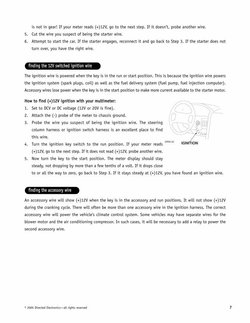
The ignition wire is powered when the key is in the run or start position. This is because the ignition wire powers
the ignition system (spark plugs, coil) as well as the fuel delivery system (fuel pump, fuel injection computer).
Accessory wires lose power when the key is in the start position to make more current available to the starter motor.
HHooww ttoo ffiinndd ((++))1122VV iiggnniittiioonn wwiitthh yyoouurr mmuullttiimmeetteerr::
1. Set to DCV or DC voltage (12V or 20V is fine).
2. Attach the (-) probe of the meter to chassis ground.
3. Probe the wire you suspect of being the ignition wire. The steering
column harness or ignition switch harness is an excellent place to find
this wire.
4. Turn the ignition key switch to the run position. If your meter reads
(+)12V, go to the next step. If it does not read (+)12V, probe another wire.
5. Now turn the key to the start position. The meter display should stay
steady, not dropping by more than a few tenths of a volt. If it drops close
to or all the way to zero, go back to Step 3. If it stays steady at (+)12V, you have found an ignition wire.
An accessory wire will show (+)12V when the key is in the accessory and run positions. It will not show (+)12V
during the cranking cycle. There will often be more than one accessory wire in the ignition harness. The correct
accessory wire will power the vehicle's climate control system. Some vehicles may have separate wires for the
blower motor and the air conditioning compressor. In such cases, it will be necessary to add a relay to power the
second accessory wire.
ffiinnddiinngg tthhee aacccceessssoorryy wwiirree
ffiinnddiinngg tthhee 1122VV sswwiittcchheedd iiggnniittiioonn wwiirree

88 © 2005 Directed Electronics—all rights reserved
Most vehicles use a (+) parking light circuit. The (+) parking light wire is often found near the light switch. In
many vehicles the light switch is built into the turn signal lever; in these vehicles the parking light wire can be
found in the steering column. The same wire can often be accessed in the kick panel or running board.
NNOOTTEE:: Many Toyotas and other Asian vehicles, send a (-) signal from the switch to a relay. Therelay then sends (+)12V to the bulbs. Whenever you have difficulty finding a (+) parking lightwire near the switch, simply test the wires at any switch or control panel that is lit by the instru-ment panel lighting. Remember, you need a (+) parking light wire that does not vary with thedimmer setting.
HHooww ttoo ffiinndd aa ((++)) ppaarrkkiinngg lliigghhtt ffllaasshh wwiirree wwiitthh yyoouurr mmuullttiimmeetteerr::
1. Set to DCV or DC voltage (12V or 20V is fine).
2. Attach the (-) probe of the meter to chassis ground.
3. Probe the wire you suspect of being the parking light wire. Usually, the area near the headlight/parking light
switch is an excellent area to start, as is the kick panel.
4. Turn on the parking lights. If your meter shows (+)12V, turn off the parking lights and make sure it goes back
to zero.
5. If it does return to zero, turn the parking lights back on and, using the dash light dimmer control, turn the
brightness of the dash lights up and down. If the meter changes more than a volt when using the dimmer,
look for another wire. If it stays relatively close to (+)12V, you have found your parking light wire.
NNOOTTEE:: Vehicles that use a (-) signal from the switch to the factory relay may be interfaceddirectly. (See H1/5 WHITE wire of Primary Harness (H1) Wire Connection Guide section.)
To test for a tachometer wire, a multimeter capable of testing AC voltage must be used. The tachometer wire will
show between 1V and 6V AC. In multi-coil ignition systems, the system can learn individual coil wires. Individual
coil wires in a multi-coil ignition system will register lower amounts of AC voltage. Also, if necessary, the system
ffiinnddiinngg tthhee ttaacchhoommeetteerr wwiirree
ffiinnddiinngg aa ((++)) ppaarrkkiinngg lliigghhtt wwiirree
© 2005 Directed Electronics—all rights reserved 99
can use a fuel injector control wire for engine speed sensing. Common locations for a tachometer wire are the
ignition coil itself, the back of the gauges, engine computers, and automatic transmission computers.
IIMMPPOORRTTAANNTT!! Do not test tachometer wires using a test light or logic probe. The vehicle will bedamaged.
HHooww ttoo ffiinndd aa ttaacchhoommeetteerr wwiirree wwiitthh yyoouurr mmuullttiimmeetteerr::
1. Set to ACV or AC voltage (12V or 20V is fine).
2. Attach the (-) probe of the meter to chassis ground.
3. Start and run the vehicle.
4. Probe the wire you suspect of being the tachometer wire with the red probe of the meter.
5. If this is the correct wire the meter will read between 1V and 6V.
In diesel vehicles it is necessary to interface with the wire that turns on the WAIT-TO-START light in the dash-
board. This wire illuminates the bulb until the vehicle’s glow plugs are properly heated. When the light goes out
the vehicle can be started. This wire is always available at the connector leading to the bulb in the dashboard.
It can also be found at the Engine Control Module (ECM) in many vehicles.
TToo tteesstt aanndd ddeetteerrmmiinnee tthhee ppoollaarriittyy ooff tthhiiss wwiirree::
1. Set your multimeter to DCV or DC voltage (12 or 20V is fine).
2. Attach the (+) probe of the meter to (+)12V.
3. Probe the wire that you suspect leads to the bulb with the (-) probe of the meter.
4. Turn the ignition switch to the ON position.
5. If the meter indicates 12 volts until the light goes out you have isolated the correct wire and the wire's polar-
ity is negative (ground while the bulb is on).
6. If the meter reads zero volts until the light goes out and then reads 12 volts, you have isolated the correct
wire and the wire's polarity is positive.
ffiinnddiinngg tthhee wwaaiitt--ttoo--ssttaarrtt bbuullbb wwiirree ffoorr ddiieesseellss

1100 © 2005 Directed Electronics—all rights reserved
pprriimmaarryy hhaarrnneessss ((HH11)) wwiirriinngg ddiiaaggrraamm______
______
______
______
______
______
______
______
______
44--ppiinn ssaatteelllliittee hhaarrnneessss ddiiaaggrraamm______
______
______
______ PPIINNKK IIGGNNIITTIIOONN TTRRIIGGGGEERR
PPUURRPPLLEE SSTTAARRTTEERR TTRRIIGGGGEERR
OORRAANNGGEE AACCCCEESSSSOORRYY TTRRIIGGGGEERR
BBLLUUEE SSTTAATTUUSS OOUUTTPPUUTT11
22
33
44
WWHHIITTEE ((++//--)) LLIIGGHHTT FFLLAASSHH
BBLLAACCKK GGRROOUUNNDD
RREEDD//WWHHIITTEE CCHHAANNNNEELL 22 ((VVAALLIIDDIITTYY OONNLLYY))
WWHHIITTEE//RREEDD ((++)) AACCTTIIVVAATTIIOONN IINNPPUUTT
GGRRAAYY//BBLLAACCKK ((--)) WWAAIITT TTOO SSTTAARRTT IINNPPUUTT
WWHHIITTEE//BBLLUUEE ((--)) AACCTTIIVVAATTIIOONN IINNPPUUTT
YYEELLLLOOWW ((++)) IIGGNNIITTIIOONN OOUUTT ((TTOO AALLAARRMM))
GGRREEEENN//WWHHIITTEE FFAACCTTOORRYY RREEAARRMM
LLIIGGHHTT GGRREEEENN//BBLLAACCKK FFAACCTTOORRYY AALLAARRMM DDIISSAARRMMHH11//11
HH11//22
HH11//33
HH11//44
HH11//55
HH11//66
HH11//77
HH11//88
HH11//99

© 2005 Directed Electronics—all rights reserved 1111
hheeaavvyy ggaauuggee rreellaayy wwiirriinngg ddiiaaggrraamm______
______
______
______
______
______
ddoooorr lloocckk hhaarrnneessss,, 33--ppiinn ccoonnnneeccttoorr______
______
______
NNoottee:: Refer to TechTip 1041 for wiring information.
rreemmoottee ssttaarrtt hhaarrnneessss ((HH22)) wwiirriinngg ddiiaaggrraamm______
______
______
______
______ BBLLUUEE//WWHHIITTEE ((--)) 220000 mmAA 22NNDD SSTTAATTUUSS//RREEAARR DDEEFFOOGGGGEERR OOUUTTPPUUTT
GGRRAAYY ((--)) HHOOOODD PPIINNSSWWIITTCCHH SSHHUUTTDDOOWWNN WWIIRREE
BBRROOWWNN ((++)) BBRRAAKKEE SSWWIITTCCHH SSHHUUTTDDOOWWNN WWIIRREE
VVIIOOLLEETT//WWHHIITTEE TTAACCHHOOMMEETTEERR IINNPPUUTT WWIIRREE
BBLLAACCKK//WWHHIITTEE ((--)) NNEEUUTTRRAALL SSAAFFEETTYY SSWWIITTCCHH IINNPPUUTTHH22//11
HH22//22
HH22//33
HH22//44
HH22//55
BBLLUUEE ((--)) UUNNLLOOCCKK OOUUTTPPUUTT
EEMMPPTTYY NNOOTT UUSSEEDD
GGRREEEENN ((--)) LLOOCCKK OOUUTTPPUUTT11
22
33
RREEDD ((++)) ((3300AA)) HHIIGGHH CCUURRRREENNTT 1122VV IINNPPUUTT
PPIINNKK//WWHHIITTEE ((++)) PPRROOGGRRAAMMMMAABBLLEE OOUUTTPPUUTT FFOORR AACCCCEESSSSOORRYY OORR IIGGNNIITTIIOONN
RREEDD ((++)) ((3300AA)) HHIIGGHH CCUURRRREENNTT 1122VV IINNPPUUTT
OORRAANNGGEE ((++)) ((3300 AAMMPP)) OOUUTTPPUUTT TTOO AACCCCEESSSSOORRYY CCIIRRCCUUIITT
PPUURRPPLLEE ((++)) ((3300 AAMMPP)) OOUUTTPPUUTT TTOO SSTTAARRTTEERR CCIIRRCCUUIITT
PPIINNKK ((++)) ((3300 AAMMPP)) OOUUTTPPUUTT TTOO IIGGNNIITTIIOONN CCIIRRCCUUIITT11
22
33
44
55
66

1122 © 2005 Directed Electronics—all rights reserved
pprriimmaarryy hhaarrnneessss ((HH11)),, 99--ppiinn ccoonnnneeccttoorr
This wire sends a negative pulse every time the remote start is activated or the doors are unlocked. This can be
used to pulse the disarm wire of the vehicle's factory anti-theft device. Use a relay to send a (-) or (+) pulse to
the disarm wire as shown in the following diagrams.
RReellaayy ffoorr NNeeggaattiivvee ((--)) DDiissaarrmm WWiirree RReellaayy ffoorr PPoossiittiivvee ((++)) DDiissaarrmm WWiirree
This wire sends a negative pulse every time the remote start shuts down or the doors are locked. This can be
used to pulse the arm wire of the vehicle's factory anti-theft device. Use a relay to send a (-) or (+) pulse to the
arm wire
AAss aa ssttaanndd--aalloonnee ssyysstteemm:: The H1/3 YELLOW wire should not be connected to anything.
AAss aann aadddd--oonn ccaarr ssttaarrtteerr:: If connected, disconnect the ignition/accessory input of the remote controlled secu-
rity or keyless entry system. Connect the H1/3 YELLOW ignition output to the ignition/accessory input of the
remote controlled security or keyless entry system. The wire will prevent the host system from sensing that the
ignition is on during remote start operation.
This input comes from the factory set to 2 activation pulses. This means that it is necessary to have 2 consecu-
tive ground pulses on the white/blue wire for the remote start to activate or to deactivate. The same holds true
for the remote control activation when set to a two pulse setting it is necessary to press the button twice
for the remote start to activate or deactivate.
HH11//44 WWHHIITTEE//BBLLUUEE rreemmoottee ssttaarrtt ((--)) aaccttiivvaattiioonn iinnppuutt
HH11//33 YYEELLLLOOWW ((++)) iiggnniittiioonn oouuttppuutt ttoo RRFF ssyysstteemm
HH11//22 GGRREEEENN//WWHHIITTEE ffaaccttoorryy rreeaarrmm
HH11//11 LLIIGGHHTT GGRREEEENN//BBLLAACCKK ((--)) ffaaccttoorryy aallaarrmm ddiissaarrmm

© 2005 Directed Electronics—all rights reserved 1133
NNOOTTEE:: When the activation pulse count can be programmed to 1, 2, or 3 pulses when changed itwill affect both activation inputs; the White/Blue wire and the remote control activation.
Connect this wire to the wire in the vehicle that sends the signal to turn on the WAIT-TO-START bulb in the dash-
board. In most diesels the wire is negative (ground turns on the bulb) and the GRAY/BLACK can be directly
connected to the wire in the vehicle. If the vehicle uses a positive wire (12V to turn on the bulb) a relay must
be used to change the polarity. (See Finding the Wires You Need section for testing procedures.) Here are some
common colors of this wire:
■ Chevrolet and GMC trucks: Light Blue or Dark Blue
■ Ford Trucks: Black/Pink
■ Dodge Ram Trucks: Orange/Black or Black/Orange
NNOOTTEE!! A 1-amp diode must be installed in line on the factory wire between the wait-to-start indi-cator and the ECM. (See the following diagram for details.)
HH11//55 GGRRAAYY//BBLLAACCKK ((--)) ddiieesseell wwaaiitt--ttoo--ssttaarrtt bbuullbb iinnppuutt

1144 © 2005 Directed Electronics—all rights reserved
This input comes from the factory set to 2 activation pulses. This means that it is necessary to have 2 consecu-
tive 12V pulses on the white/blue wire for the remote start to activate or to deactivate. The same holds true for
the remote control activation when set to a two pulse setting it is necessary to press the button twice for
the remote start to activate or deactivate.
NNOOTTEE:: When the activation pulse count can be programmed to 1, 2, or 3 pulses when changed itwill affect both activation inputs; the White/Red wire and the remote control activation.
When the system receives the code controlling Channel 2, for longer than 1.5 seconds, the RED/WHITE wire will
supply an output as long as the transmission continues. This is often used to operate a trunk/hatch release or
other relay-driven function.
IIMMPPOORRTTAANNTT!! Never use this wire to drive anything except a relay or low-current input! The transistorized output
can only supply 200 mA of current. Connecting directly to a solenoid, motor, or other high-current device will
cause it to fail.
HH11//77 RREEDD//WWHHIITTEE CChhaannnneell 22,, ((--)) 220000 mmAA oouuttppuutt
HH11//66 WWHHIITTEE//RREEDD ((++)) aaccttiivvaattiioonn iinnppuutt
© 2005 Directed Electronics—all rights reserved 1155
Remove any paint and connect this wire to bare metal, preferably with a factory bolt rather than your own screw.
(Screws tend to either strip or loosen with time.) We recommend grounding all your components to the same
point in the vehicle.
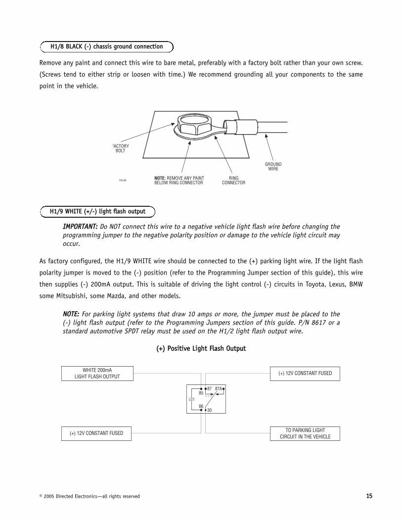
IIMMPPOORRTTAANNTT:: Do NOT connect this wire to a negative vehicle light flash wire before changing theprogramming jumper to the negative polarity position or damage to the vehicle light circuit mayoccur.
As factory configured, the H1/9 WHITE wire should be connected to the (+) parking light wire. If the light flash
polarity jumper is moved to the (-) position (refer to the Programming Jumper section of this guide), this wire
then supplies (-) 200mA output. This is suitable of driving the light control (-) circuits in Toyota, Lexus, BMW
some Mitsubishi, some Mazda, and other models.
NNOOTTEE:: For parking light systems that draw 10 amps or more, the jumper must be placed to the (-) light flash output (refer to the Programming Jumpers section of this guide. P/N 8617 or astandard automotive SPDT relay must be used on the H1/2 light flash output wire.
((++)) PPoossiittiivvee LLiigghhtt FFllaasshh OOuuttppuutt
HH11//99 WWHHIITTEE ((++//--)) lliigghhtt ffllaasshh oouuttppuutt
HH11//88 BBLLAACCKK ((--)) cchhaassssiiss ggrroouunndd ccoonnnneeccttiioonn

1166 © 2005 Directed Electronics—all rights reserved
((--)) LLiigghhtt FFllaasshh OOuuttppuutt
hheeaavvyy ggaauuggee rreellaayy iinntteerrffaacceeThe heavy gauge wires are used to energize high current circuits in the vehicle. It is crucial that these connec-
tions are made correctly so that they are capable of handling the current demands. For this reason, scotch locks,
T-taps and other such connectors should not be used.
Remove the two 30 amp fuses prior to connecting these wires and do not replace them until the satellite has
been plugged into the control module. These wires are the source of current for all the circuits the relay satel-
lite will energize. They must be connected to a high current source. Since the factory supplies (+) 12V to the key
switch that is used to operate the motor, it is recommended that these wires be connected there.
NNOOTTEE:: If the factory supplies two separate (+) 12V feeds to the ignition switch, connect one REDwire of the satellite to each feed at the switch.
Connect this wire to the ignition wire in the vehicle. (See Finding the Wires You Need section of this guide.)
Connect this wire to the accessory wire in the vehicle that powers the climate control system. (See Finding the
Wires You Need section of this guide.)
Connect this wire to the starter wire in the vehicle. (See Finding the Wires You Need section of this guide.)
PPUURRPPLLEE ((++)) ssttaarrtteerr oouuttppuutt
OORRAANNGGEE ((++)) aacccceessssoorryy oouuttppuutt
PPIINNKK ((++)) iiggnniittiioonn oouuttppuutt
RREEDD ((22)) ((++))1122VV iinnppuutt ffoorr rreellaayyss
© 2005 Directed Electronics—all rights reserved 1177
Connect this wire to the second ignition or accessory wire in the vehicle. (Selectable by using Feature 9.)
NNOOTTEE:: For vehicles that do not have a second ignition or accessory wire, this connection is notrequired.
rreemmoottee ssttaarrtt hhaarrnneessss ((HH22)),, 55--ppiinn ccoonnnneeccttoorr
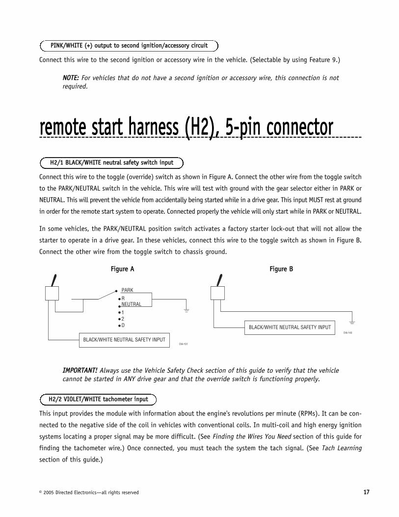
Connect this wire to the toggle (override) switch as shown in Figure A. Connect the other wire from the toggle switch
to the PARK/NEUTRAL switch in the vehicle. This wire will test with ground with the gear selector either in PARK or
NEUTRAL. This will prevent the vehicle from accidentally being started while in a drive gear. This input MUST rest at ground
in order for the remote start system to operate. Connected properly the vehicle will only start while in PARK or NEUTRAL.
In some vehicles, the PARK/NEUTRAL position switch activates a factory starter lock-out that will not allow the
starter to operate in a drive gear. In these vehicles, connect this wire to the toggle switch as shown in Figure B.
Connect the other wire from the toggle switch to chassis ground.
FFiigguurree AA FFiigguurree BB
IIMMPPOORRTTAANNTT!! Always use the Vehicle Safety Check section of this guide to verify that the vehiclecannot be started in ANY drive gear and that the override switch is functioning properly.
This input provides the module with information about the engine's revolutions per minute (RPMs). It can be con-
nected to the negative side of the coil in vehicles with conventional coils. In multi-coil and high energy ignition
systems locating a proper signal may be more difficult. (See Finding the Wires You Need section of this guide for
finding the tachometer wire.) Once connected, you must teach the system the tach signal. (See Tach Learning
section of this guide.)
HH22//22 VVIIOOLLEETT//WWHHIITTEE ttaacchhoommeetteerr iinnppuutt
HH22//11 BBLLAACCKK//WWHHIITTEE nneeuuttrraall ssaaffeettyy sswwiittcchh iinnppuutt
PPIINNKK//WWHHIITTEE ((++)) oouuttppuutt ttoo sseeccoonndd iiggnniittiioonn//aacccceessssoorryy cciirrccuuiitt
1188 © 2005 Directed Electronics—all rights reserved
This wire MUST be connected to the vehicle's brake light wire. This is the wire that shows (+) 12V when the brake
pedal is depressed. The remote start will be disabled or shut down any time the brake pedal is depressed.
This wire MUST be connected to the hood pinswitch. This input will disable or shut down the remote start when
the hood is opened.
This wire supplies a 200mA output as soon as the module begins the remote start process. The H2/5 BLUE/WHITE
wire can also be used to activate the defogger trigger (latched/pulsed) 10 seconds after successful remote start.
(See the Feature Descriptions section in this guide for details about programming this output.)
nneeuuttrraall ssaaffeettyy sswwiittcchh iinntteerrffaacceeSome vehicles combine the column shift mechanism and the mechanical neutral safety switch into one mechan-
ical part. In these vehicles, it is impossible to interface the remote start system before the neutral safety switch.
With this type of vehicle, if the vehicle is left in a drive gear and the remote start system is activated, the vehicle
will move and may cause damage to persons or property.
According to available information, vehicles known to be manufactured this way are most General Motors trucks,
sport utility vehicles and column shifting passenger vehicles. Available information also indicates that pre-1996
Dodge Dakota pickups with 2.5 liter motors are also manufactured this way.
GM vehicles that have the neutral safety switch built into the column shifter can usually be identified by a purple
starter wire. Typically, vehicles that use an outboard mechanical switch use a yellow wire from the ignition switch
to the mechanical switch and a purple wire from the mechanical switch to the starter itself. Remember, this is
only a rule of thumb and is not intended as a substitute for proper testing.
IIMMPPOORRTTAANNTT!! Please see vehicle Safety Check section of this guide for testing procedures.
Vehicles with the neutral safety switch built into the column shifter require that the shifter be placed in park in
order to remove the keys from the ignition. As a result, it is possible to use the key-in-ignition sense switch to
prevent remote starting if the keys are in the ignition. (See General Motors Trucks, SUVs and Column-Shifting
Passenger Cars and Pre-1996 Dodge Dakota Pickups with 2.5 Liter Motors diagrams in this section on how to
accomplish this.) The first diagram applies to all General Motors vehicles as of the date of this guide’s publica-
tion. The second diagram applies to all pre-1996 Dodge Dakota pickup trucks with 2.5 liter motors. This solution
HH22//55 BBLLUUEE//WWHHIITTEE ssttaattuuss//ddeeffooggggeerr oouuttppuutt
HH22//44 GGRRAAYY ((--)) hhoooodd ppiinnsswwiittcchh iinnppuutt
HH22//33 BBRROOWWNN ((++)) bbrraakkee sswwiittcchh iinnppuutt

© 2005 Directed Electronics—all rights reserved 1199
has one side effect: If the customer inserts the key in the ignition with the driver's door open, the remote start
system will shut down. If this interface is used, it is important to inform the customer that the driver’s door must
be closed before inserting the key into the ignition when the remote start is active. This will allow the customer
to turn the key on and shut the remote start down by pressing the brake, without the key sense wire shutting
down the unit prematurely.
You must also connect the H2/4 BROWN (+) shut-down input to the yellow wire on the relay satellite
ribbon cable. This prevents the remote start system from activating if the key is left in the “run” position. You
must use diodes to isolate the ignition circuit from the brake switch circuit as shown in the diagram below.
IIMMPPOORRTTAANNTT!! Once the interface is complete, attempt to remote start the vehicle with the doorclosed and the key in the ignition. The vehicle should not start. If it does, re-check the connections.
As of the date of this guide’s publication, the following list describes the types of vehicles that are known to
have a mechanical neutral safety switch instead of an electrical neutral safety circuit. The model years will vary
from vehicle to vehicle. This list will be updated periodically as new information is available; installers are
encouraged to call DIRECTED Technical Support at 1-800-753-0800 with updated information.
■ Pre-1996 Dodge Dakota pickups with 2.5 liter engines
■ GM "B" Platform: Caprice, Impala SS and Roadmaster
■ GM "D" Platform: Cadillac Fleetwood and Fleetwood Brougham
■ GM "P" Series: Commercial Van
■ GM "L/M" Series: Astro, Safari
■ GM "C/K" Series: Full-size pickup, Sierra, Suburban, Tahoe, Yukon
■ GM "S/T" Series: Blazer, Bravada, Jimmy, pickup, Sonoma
■ GM "G" Series: Express, Savanah
���������������������������� ��� ��
���� �����������������
�������������������
�����������
�����������������

2200 © 2005 Directed Electronics—all rights reserved
pprree--11999966 ddooddggee ddaakkoottaa ppiicckkuuppss wwiitthh 22..55 lliitteerr mmoottoorrss
ggeenneerraall mmoottoorrss ttrruucckkss,, SSUUVVss,, aanndd ccoolluummnn sshhiiffttiinngg ppaasssseennggeerr ccaarrss

© 2005 Directed Electronics—all rights reserved 2211
bbyyppaassssiinngg GGMM vveehhiiccllee aannttii--tthheefftt ssyysstteemmss ((VVAATTSS))Vehicles with the GM VATS (Pass Key) systems have a resistor embedded in the ignition key. If the VATS decoder
module does not measure the proper resistance when the vehicle is started, the starter and fuel pump may be dis-
abled for up to ten minutes. An optional "VATS pack" of resistors is available ((pp//nn 665522TT)). One of the resistors in the
pack will match the resistor in the key.
The VATS wires will be two very light-gauge wires coming out of the steering column. The colors of the wires vary,
but they are often contained in orange tubing - either both will be white wires, or one wire will be purple/white
and the other white/black. Determine the value of the resistor in the key. Then follow the diagram below to
bypass VATS during remote start operation. If the BLUE status output from the relay satellite has been pro-
grammed for factory security re-arm, then use the (H3/5) BLUE/WHITE 2nd status output from the control module
to control the relay.
NNOOTTEE:: When connecting to the VATS wires, it is not important which wire is cut.
������ ���������
�������������������
�
!"�
# #
����$���������������
%
%
���
��������������������
���������������&�����
����������
����� �
��
��������������
�������

2222 © 2005 Directed Electronics—all rights reserved
11999955 aanndd nneewweerr vveehhiiccllee aannttii--tthheefftt ssyysstteemmss((iimmmmoobbiilliizzeerrss))1995 and newer vehicle anti-theft systems (immobilizers) require a bypass module. The bypass module allows for
easy interfacing, while still maintaining the OEM system’s integrity.
The Passlock I and Passlock II systems can be found in the following General Motors vehicles:
■ ‘95 and newer Cavalier and Sunfire
■ ‘96 and newer Achieva, Grand Am, and Skylark
■ ‘97 and newer Intrigue, Malibu, and Cutlass
■ ‘98 and newer trucks, vans, SUVs
■ ‘99 and newer Alero
■ 2000 and newer Impala and Saturn
Passlock I and II systems are VATS-evolved. Passlock systems still rely on the R-code to start, but the pellet is no
longer placed in the key. The resistor can now be found in the key switch. This allows for a greater number of
possible R-codes. In addition, Passlock systems require “seeing” the correct R-code at the correct time. To bypass
Passlock I and II, pp//nn 555555LL or pp//nn 555555TT is required.
The Passkey III system can be found in the following vehicles:
■ ‘97 and newer Park Avenue
■ ‘98 and newer Cadillac
■ ‘99 and newer U vans, Transport, Montana, and Silhouette
■ 2000 and newer Grand Prix, Lesabre, Monte Carlo, Lumina, Bonneville
■ 2001 and newer Aurora, Aztek and Rendezvous
Other transponder-based systems include: Acura, BMW, Dodge/Chrysler/Jeep, Ford, Honda, Infinity, Mazda,
Mercedes, Mitsubishi, Nissan, Toyota, Volkswagon, and Volvo.
PK-3 and the transponder-based systems use a transponder system that locks out the ignition and fuel system.
This transponder system is comprised of two parts. The first part, the transceiver, circles the key switch and is
activated when the key is placed in the key switch or turned to the run position. Upon activation, the transceiver
ppaasssskkeeyy IIIIII ((PPKK--33)),, ttrraannssppoonnddeerr--bbaasseedd ssyysstteemmss
ppaasssslloocckk II aanndd ppaasssslloocckk IIII ((PPLL--11 aanndd PPLL--22))
© 2005 Directed Electronics—all rights reserved 2233
will excite the transponder, which is located (but not visible) in the head of the ignition key. The key transpon-
der will then send a unique code back to the transceiver for evaluation. If the code matches a valid code of the
system, the vehicle will be allowed to start. Most of these transponder-based systems can be bypassed using pp//nn
555555UU.. Some may require additional parts from the vehicle manufacturer. Consult you dealer for the applications.
For most Ford PATS transponders, pp//nn 555555FF can be used, except for the following vehicles, which will require pp//nn
555555UU: ‘97 and newer Mark VII, and 2000 and newer Taurus/Sable, Contour/Mystique and Focus.
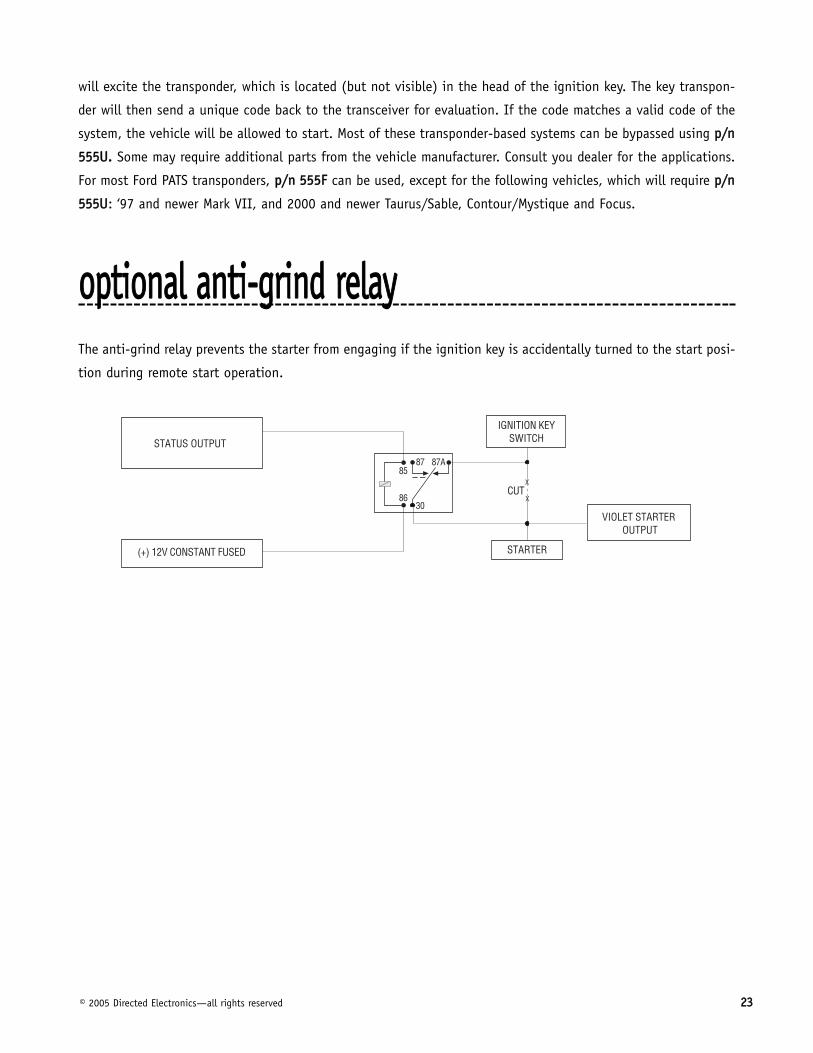
ooppttiioonnaall aannttii--ggrriinndd rreellaayyThe anti-grind relay prevents the starter from engaging if the ignition key is accidentally turned to the start posi-
tion during remote start operation.

2244 © 2005 Directed Electronics—all rights reserved
pprrooggrraammmmiinngg jjuummppeerrss
This jumper is used to determine the light flash output polarity. In the (+) position, the on-board relay is enabled
and the unit will output (+)12V on the WHITE wire, H1/2. In the (-) position, the on-board relay is disabled. The
WHITE wire, H1/2, will supply a 200mA (-) output suitable for driving factory parking light relays.
NNOOTTEE:: For parking light circuits that draw 10 amps or more, the internal jumper must be switchedto a (-) light flash output. PP//NN 88661177 or a standard automotive SPDT relay must be used on theH1/2 light flash output harness wire.
In most cases, this jumper can be left in the OFF position. Some new vehicles use less than 12 volts in their
ignition systems. The unit may have trouble learning the tach signal in these vehicles. Changing the jumper to
the ON setting changes the trigger threshold of the digital tach circuit so it will work properly with these vehi-
cles. The vehicles affected include many newer Dodge/Chrysler/Plymouth vehicles, such as the Neon, Cirrus,
Stratus, Breeze and LH-based vehicles.
ttaacchh tthhrreesshhoolldd oonn//ooffff
lliigghhtt ffllaasshh ((++))//((--))

© 2005 Directed Electronics—all rights reserved 2255
pplluugg--iinn pprrooggrraamm sswwiittcchhThe Program switch plugs into the blue two-pin connector.
2266 © 2003 Directed Electronics, Inc. Vista, CA
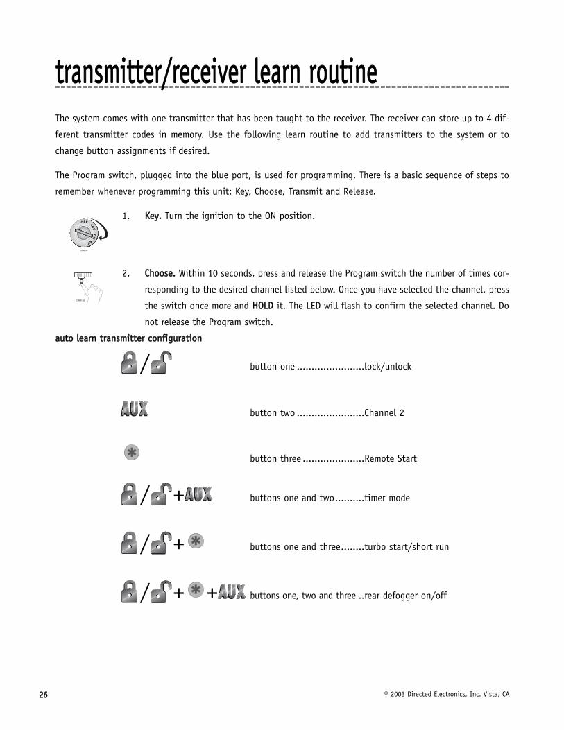
ttrraannssmmiitttteerr//rreecceeiivveerr lleeaarrnn rroouuttiinneeThe system comes with one transmitter that has been taught to the receiver. The receiver can store up to 4 dif-
ferent transmitter codes in memory. Use the following learn routine to add transmitters to the system or to
change button assignments if desired.
The Program switch, plugged into the blue port, is used for programming. There is a basic sequence of steps to
remember whenever programming this unit: Key, Choose, Transmit and Release.
1. KKeeyy.. Turn the ignition to the ON position.
2. CChhoooossee.. Within 10 seconds, press and release the Program switch the number of times cor-
responding to the desired channel listed below. Once you have selected the channel, press
the switch once more and HHOOLLDD it. The LED will flash to confirm the selected channel. Do
not release the Program switch.
aauuttoo lleeaarrnn ttrraannssmmiitttteerr ccoonnffiigguurraattiioonn
/ button one .......................lock/unlock
button two .......................Channel 2
button three .....................Remote Start
/ + buttons one and two..........timer mode
/ + buttons one and three........turbo start/short run
/ + + buttons one, two and three ..rear defogger on/off

© 2005 Directed Electronics—all rights reserved 2277
3. TTrraannssmmiitt.. While HHOOLLDDIINNGG the Program switch, press the button on the transmitter that you
would like to control the selected receiver channel.
4. RReelleeaassee.. Once the code is learned, the Program switch can be released.
You can advance from programming one channel to another by releasing the Program switch and tapping it to
advance steps and then holding it. For instance: You have programmed Channel One and you want to program
Channel Two. Release the Program switch. Press it one time and release it to advance from Channel One to
Channel Two. Now, press and HHOOLLDD the Program switch. The LED will flash two times. As before, do not release
it.
If you want to program Channel Three after programming Channel One, release the Program switch, press it twice
and release it to advance to Channel Three. Then press it once more and HHOOLLDD it. The LED will flash three times
to confirm it is ready to receive the code from the transmitter.
LLeeaarrnn RRoouuttiinnee wwiillll bbee eexxiitteedd iiff::
■ Ignition is turned off.
■ Program switch is pressed too many times.
■ More than 25 seconds elapses between programming steps.
CCHHAANNNNEELL NNUUMMBBEERR FFUUNNCCTTIIOONN
1 Auto-Learn*
2 Lock/Unlock
3 Channel 2 output
4 Remote Start
5 Turbo/Short Run
6 Timer Mode
7 Defogger Control
8 Delete all Transmitters**
**NNOOTTEE:: For Auto Learn Configurations, see Transmitter Configurations section of thisguide.
****NNOOTTEE:: If any button from a known transmitter is programmed to Channel 8, alltransmitters will be erased from memory and will revert to the default feature set-tings. This is useful in cases where the customer's transmitters are lost or stolen.

2288 © 2005 Directed Electronics—all rights reserved
ttaacchh lleeaarrnniinngg
1. Start the vehicle with the key.
2. Within 5 seconds, press and HHOOLLDD the Program switch.
3. The LED will light constant when the tach signal is learned.
4. Release the Program switch.
ooppeerraattiinngg sseettttiinnggss lleeaarrnn rroouuttiinneeThe System Features Learn Routine dictates how the unit operates. The programmable operating settings of this
unit can be changed whenever necessary through the computer-based Learn Routine. The Program push-button
switch, plugged into the blue port, is used together with a programmed transmitter to change the settings. It is
possible to access and change any of the feature settings using the Program switch. To program settings, remem-
ber: Key, Choose, Transmit and Release.
TToo pprrooggrraamm tthhee lleeaarrnn rroouuttiinnee::
1. KKeeyy.. Turn the ignition on and then back off.
2. CChhoooossee.. Within 10 seconds, press and release the Program switch the number of times cor-
responding to the feature number you want to program. (See Features Menu section.)
Once the Program switch has been pressed and released the desired number of times, press it once more and
HHOOLLDD it. After a second, the LED will flash to indicate which feature you have accessed. For example, groups of
eight flashes would indicate access to the status output feature (Feature 8).
DRW-96
ttoo lleeaarrnn tthhee ttaacchh ssiiggnnaall
© 2005 Directed Electronics—all rights reserved 2299
3. TTrraannssmmiitt.. The transmitter is used to select the desired setting. As shipped, the unit is con-
figured to the LED ON settings. These are called the default settings. Pressing Channel One
(usually Button I) will set it to the LED ON setting. The LED will light solid (stop flashing)
to indicate the setting. Pressing Channel 2 (usually Button II) will change the setting to
the LED OFF setting. The LED will go out indicating the change.
4. RReelleeaassee.. The Program switch can now be released.
You can advance from feature to feature by pressing and releasing the Program switch the number of times nec-
essary to get from the feature you just programmed to the feature you wish to access. For example, if you just
programmed the run time (Feature 3) and you next want to program parking lights (Feature 4) to constant,
release the Program switch. Press and release it once to advance from Feature 3 to Feature 4. Then press it once
more and HHOOLLDD it. The LED will flash in groups of 4 to confirm that you have accessed Feature 4.
TThhee lleeaarrnn rroouuttiinnee wwiillll bbee eexxiitteedd iiff aannyy ooff tthhee ffoolllloowwiinngg ooccccuurrss::
■ The ignition is turned on.
■ The Program switch is pressed too many times.
■ More than 25 seconds elapses between programming steps.

3300 © 2005 Directed Electronics—all rights reserved
ffeeaattuurreess mmeennuuThe factory default settings are indicated in bboolldd text in the table below.
FFEEAATTUURREE DDEEFFAAUULLTT -- LLEEDD OONN SSEETTTTIINNGG LLEEDD OOFFFF SSEETTTTIINNGG NNUUMMBBEERR ((PPRREESSSS CCHHAANNNNEELL 11)) ((PPRREESSSS CCHHAANNNNEELL 22))
1 EEnnggiinnee cchheecckkiinngg oonn Engine checking off
2 TTaacchhoommeetteerr cchheecckkiinngg ttyyppee Voltage checking type
3 1122 mmiinnuutteess rruunn ttiimmee (1)** 24 minutes (2)*, 60 minutes (3) run time
4 FFllaasshhiinngg ppaarrkkiinngg lliigghhtt oouuttppuutt Constant parking light output
5 CCrraannkkiinngg ttiimmee 00..66 sseecc.. (1) Cranking time 0.8 (2), 1.0 (3), 1.2 (4), 1.4 (5),1.6 (6), 1.8 (7), 2.0 (8), 4.0 (9) sec.
6 VVoollttaaggee cchheecckk hhiigghh lleevveell Voltage check low level
7 SShhoorrtt RRuunn ((ttuurrbboo ttiimmeerr)):: 11 (1) mmiinn Short Run (turbo timer) 3 (2), 5 (3), 10 (4) min.
8 Activation pulse: 1 (1) AAccttiivvaattiioonn ppuullsseess:: 22 (2), 3 (3)
9 IIggnniittiioonn//aacccceessssoorryy oouuttppuutt:: IIggnniittiioonn Ignition/accessory output: Accessory
10 AAcccceessssoorryy ssttaattee dduurriinngg wwaaiitt ttoo ssttaarrtt:: OOFFFF Accessory state during wait to start: ON
11 22nndd ssttaattuuss oouuttppuutt:: NNoorrmmaall (1) Rear defogger latched (2)/pulsed (3)
12 DDiieesseell ttiimmeerr WWaaiitt--ttoo--SSttaarrtt iinnppuutt (1) Timed 15 (2), 30 (3), 45 (4) seconds
13 RRuunn TTiimmee ((TTiimmeerr MMooddee)) 1122 mmiinnuutteess (1) 3 (2), 6 (3), 9 (4) minutes
14 DDoooorr LLoocckk ppuullssee dduurraattiioonn 00..88 sseeccoonnddss (1) 3.5 (2), 0.4 (3) seconds
15 UUnnlloocckk oouuttppuutt 11 ppuullssee Unlock output 2 pulses
16 LLoocckk oouuttppuutt 11 ppuullssee Lock output 2 pulses
17 IIggnniittiioonn uunnlloocckk OONN Ignition unlock OFF
18 IIggnniittiioonn lloocckk OONN Ignition lock OFF
19 FFaaccttoorryy AAllaarrmm DDiissaarrmm ffuunnccttiioonn wwiitthh uunnlloocckk Before Unlock (2)/Remote Start only (3)
20 FFaaccttoorryy AAllaarrmm DDiissaarrmm 11 ppuullssee 2 pulses
21 Comfort Closure ON OOFFFF
**NNOOTTEE:: The number in parentheses indicate the number of times the LED will flash

© 2005 Directed Electronics—all rights reserved 3311
ffeeaattuurree ddeessccrriippttiioonnssThe features of the system are described below.
11 EENNGGIINNEE CCHHEECCKK——OONN/OFF:: In the default setting the remote start will monitor either the vehicle's tach wire or
voltage depending on the programming of Feature 2. If programmed off, the vehicle will crank for the programmed
crank time (Feature 5) and will not verify with tach or voltage that the vehicle is running. In the off setting, if
the vehicle fails to start, the ignition can stay on for the entire run duration. Using tach or voltage check is
always recommended if possible.
22 TTAACCHH WWIIRREE SSEENNSSEE/VOLTAGE SENSE:: If the tachometer signal wire is used, this feature must be left in the default
(tach wire connected) setting. If programmed to the voltage sense setting, the unit will crank the starter for a
preset time that can be programmed in Feature 5. Once the starter has been engaged, the system will check the
voltage level to verify the engine is running. The threshold for the voltage level test can be programmed in
Feature 6. When using voltage sense mode, connection of the H2/5 VIOLET/ WHITE tachometer input is not necessary.
33 RRUUNN TTIIMMEE——1122/24/60 MMIINNUUTTEESS:: This feature controls how long the engine will run before it “times out” and
shuts down. Programmed to the default setting the engine will run for 12 minutes. If the 24 or 60 minute run
time is desired, change this feature to the two or three flash setting.
44 PPAARRKKIINNGG LLIIGGHHTTSS——FFLLAASSHHIINNGG/CONSTANT:: In the default setting, the unit will flash the vehicle’s parking lights
while remote started. The constant setting will turn the parking lights on solidly for the entire run duration.
55 CCRRAANNKK TTIIMMEE——00..66/0.8/1.0/1.2/1.4/1.6/1.8/2.0/4.0 SSEECCOONNDDSS:: If Feature 2 is programmed to the voltage sense
setting, the crank time must be set to the appropriate duration. The default setting is 0.6 second. If a different
crank time is desired, select Feature 5 and (while pressing the Program switch) press the Channel Two button to
advance through the LED Off settings. The unit will flash the LED to indicate which time is selected. Once the
4.0 second setting is reached the next press of the Channel Two button will reset the system to the shortest
setting.
66 VVOOLLTTAAGGEE CCHHEECCKK LLEEVVEELL——HHIIGGHH/LOW:: This feature only functions when Feature 2 is programmed to voltage sense.
Some vehicles have many accessories, which are turned on when remote started. In these vehicles, the variation
of voltage between the engine off and the vehicle running is very slight and the remote start unit may “think”
the vehicle has not started. This can cause the remote start to shut down after the vehicle has been started. If
this is the case, program this feature to the LOW position.
77 SSHHOORRTT RRUUNN ((TTUURRBBOO TTIIMMEERR))——11/3/5/10 MMIINNUUTTEESS:: When the and buttons on the transmitter are
pressed simultaneously while the engine is running, the vehicle will continue to run for the short run time. The
factory default is 1 minute.

3322 © 2005 Directed Electronics—all rights reserved
88 AACCTTIIVVAATTIIOONN PPUULLSSEE CCOOUUNNTT——11/2/3 PPUULLSSEESS:: This feature allows the number of pulses to activate the remote start
feature to be changed from 1, 2, or 3 pulses. The pulse count programmed to start the vehicle will also be the
same required to shut down the remote start.
99 22nndd——IIGGNNIITTIIOONN/ACCESSORY OOUUTTPPUUTT:: This will allow the PINK/WHITE to be used as a 2nd ignition or a
2nd accessory.
1100 AACCCCEESSSSOORRYY SSTTAATTEE DDUURRIINNGG WWAAIITT--TTOO--SSTTAARRTT——OOFFFF/ON:: This will allow the programming of the accessory wire
during the wait-to-start period of a diesel motor. When ON the accessory comes on when the wait-to-start output
is activated and stays on, dropping out during crank and returning once the car has started. When OFF the acces-
sory will activate as a normal accessory.
1111 22nndd SSTTAATTUUSS OOUUTTPPUUTT——NNOORRMMAALL/LATCHED/PULSED:: If programmed to status mode, this output will turn on
when the remote start is activated. In this mode the output can be programmed to a latched or a pulsed output.
The pulsed ouput turns the defogger ON. When programmed to the latched output the status will only stay active
for 10 minutes. Both outputs activate 10 seconds after remote start.
1122 DDIIEESSEELL TTIIMMEERR——WWAAIITT--TTOO--SSTTAARRTT/15, 30, 45 SSEECCOONNDDSS:: Default is the “Wait-to-Start” input control wire, or pro-
grammable to ignore the input control wire by a delay of 15, 30, or 45 seconds.
1133 RRUUNN TTIIMMEE ((TTIIMMEERR MMOODDEE))——1122,, 3, 6, 9 MMIINNUUTTEESS:: Selects the time in minutes that the system will operate the
engine until the system "times out". This is the maximum operation period and the system may be shut down
using a shutdown at any time.
1144 DDOOOORR LLOOCCKK PPUULLSSEE DDUURRAATTllOONN——00..88,, 3.5, 0.4 SSEECCOONNDDSS:: Some European vehicles, such as Mercedes-Benz and
Audi, require longer lock and unlock pulses to operate the vacuum pump. Programming the system to provide 3.5
second pulses, will accommodate the door lock interface in these vehicles. The default setting is 0.8 second door
lock pulses. Some modification to the door lock harness (H2) is also necessary. (Refer to TechTip 1041 for wiring
information regarding (+/-) Door Lock Outputs Harness (H4)section, Type E - Mercedes-Benz and Audi -1985 and
Newer" diagram.) The 0.4 second pulse is required on some of the newer Chrysler and Ford vehicles.
1155 UUNNLLOOCCKK OOUUTTPPUUTT——11,, 2 PPUULLSSEESS:: This will program the unlock output to one or two pulses. When the double pulse
unlock feature is turned on, the BLUE (3) wire will supply two negative pulses instead of a single pulse. This
makes it possible to directly interface with double pulse vehicles without any extra parts.
1166 LLOOCCKK OOUUTTPPUUTT——11,, 2 PPUULLSSEESS:: This will program the lock output to one or two pulses. The GREEN (1) wire will
supply two negative pulses instead of a single pulse. This makes it possible to directly interface with double pulse
vehicles without any extra parts.
1177 IIGGNNIITTIIOONN CCOONNTTRROOLLLLEEDD UUNNLLOOCCKK——OONN,, OFF:: When programmed ON the doors will unlock automatically when the key
is turned off.

© 2005 Directed Electronics—all rights reserved 3333
1188 IIGGNNIITTIIOONN CCOONNTTRROOLLLLEEDD LLOOCCKK——OONN,, OFF:: When programmed ON the doors will lock when the key is on and all doors
are closed.
1199 FFAACCTTOORRYY AALLAARRMM DDIISSAARRMM——WWIITTHH UUNNLLOOCCKK,, BEFORE UNLOCK, REMOTE START ONLY:: In the default setting the factory
alarm disarm output will disarm the factory alarm system any time the button(s) controlling Unlock is pressed. The
“Before Unlock” output to disarms the factory alarm before the unlock output activates and before remote start is
activated. The “Remote Start Only” output disarms the factory alarm only before the remote start is activated.
2200 FFAACCTTOORRYY AALLAARRMM DDIISSAARRMM PPUULLSSEESS——SSIINNGGLLEE,, DOUBLE:: Selectable for a single or double-pulse for the vehicle’s factory
alarm disarm input requirements.
2211 CCOOMMFFOORRTT CCLLOOSSUURREE——ON,, OOFFFF:: The system can be programmed to close the windows when the system is armed. A
20-second output starts 200mS after the last lock pulse. The Comfort Closure output will be canceled if the unlock
button is pressed. If programmed ON, the lock output wire provides this function.
sshhuuttddoowwnn ddiiaaggnnoossttiiccssThe unit has the ability to report the cause of the last shutdown of the remote start system. To enter diagnostic mode:
1. Turn the ignition off.
2. Press and HHOOLLDD the Program switch.
3. Turn the ignition on and then off.
4. Release the Program switch.
5. Press and release the Program switch.
The LED will now report the last system shutdown by flashing for one minute in the following grouped patterns:
3344 © 2005 Directed Electronics—all rights reserved
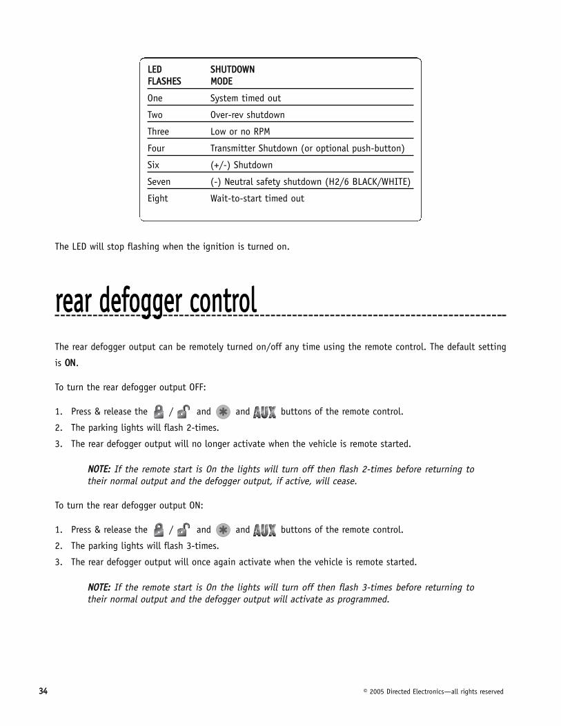
The LED will stop flashing when the ignition is turned on.
rreeaarr ddeeffooggggeerr ccoonnttrroollThe rear defogger output can be remotely turned on/off any time using the remote control. The default setting
is OONN.
To turn the rear defogger output OFF:
1. Press & release the / and and buttons of the remote control.
2. The parking lights will flash 2-times.
3. The rear defogger output will no longer activate when the vehicle is remote started.
NNOOTTEE:: If the remote start is On the lights will turn off then flash 2-times before returning totheir normal output and the defogger output, if active, will cease.
To turn the rear defogger output ON:
1. Press & release the / and and buttons of the remote control.
2. The parking lights will flash 3-times.
3. The rear defogger output will once again activate when the vehicle is remote started.
NNOOTTEE:: If the remote start is On the lights will turn off then flash 3-times before returning totheir normal output and the defogger output will activate as programmed.
LLEEDD SSHHUUTTDDOOWWNN FFLLAASSHHEESS MMOODDEE
One System timed out
Two Over-rev shutdown
Three Low or no RPM
Four Transmitter Shutdown (or optional push-button)
Six (+/-) Shutdown
Seven (-) Neutral safety shutdown (H2/6 BLACK/WHITE)
Eight Wait-to-start timed out

© 2005 Directed Electronics—all rights reserved 3355
ttiimmeerr mmooddeeBy pressing the remote / and buttons simultaneously the parking lights will flash 4 times andthen start the vehicle and run for the set duration. The remote start can be shut off by the transmitter by press-ing the remote start button and remain in timer mode, but if any other shut down zones or the ignitionbecomes active the timer mode will cancel.
1. Press Timer mode buttons.
2. The vehicle will confirm with 4 parking light flashes.
3. A 1-second delay will start.
4. The system will start the car and will run for the specified duration, unless shut down by the remote start
button (or the +/- input).
5. The system will start every 3 hours until canceled by the brake, hood, or neutral safety shut-down wires (a
maximum of 6 times).
IIMMPPOORRTTAANNTT!! Timer Mode should be used only in open areas. Never start and run the vehicle inan enclosed space such as a garage or carport.
ssaaffeettyy cchheecckkBefore vehicle reassembly, the remote system must be checked to ensure safe and trouble-free operation. The fol-
lowing test procedure must be used to verify proper installation and operation of the system. The installation
must be completed before testing, including connection to the brake switch and hood switch.
1. Test the BRAKE shutdown circuit: With the vehicle in Park (P), activate the remote start system. Once the
engine is running, press the brake pedal. The engine should shut down immediately. If the engine continues
to run, check the brake circuit connection.
2. Test the HOOD PIN shutdown circuit: With the vehicle in Park (P), open the hood. Activate the remote start
system. The vehicle should not start. If the starter engages, check your hood pin and connections.
NNOOTTEE:: If programmed for Diesel Mode, the system will turn on the ignition, but the starter shouldnot engage with the hood open.
3. Test the NEUTRAL SAFETY shutdown circuit:
IIMMPPOORRTTAANNTT!! Make sure there is adequate clearance to the front and rear of the vehicle beforeattempting this test.

3366 © 2005 Directed Electronics—all rights reserved
a. Make sure the hood is closed and no other shutdown circuits are active.
b. Set the emergency brake.
c. Turn the ignition key to the run position but do not start the engine.
d. Put the vehicle in Drive (D).
e. Put your foot over the brake pedal but do not press down on it. Be ready to step on the brake to shut-
down the remote start system.
f. Activate the remote start system.
■ If the starter engages, immediately step on the brake to shut down the system. If it does engage,
recheck the neutral safety input connection. The vehicle may use a mechanical neutral safety switch.
(See H2/6 BLACK/WHITE neutral safety switch input in Remote Start Harness Wire Connection Guide
section of this guide.)
■ If the starter does not engage, the test is complete.
Once the system passes all three tests, the vehicle can be re-assembled and delivered. Do not the use the remote
start system or finalize the installation if it fails any of the safety check tests.
ttrroouubblleesshhoooottiinngg■ TThhee iiggnniittiioonn ccoommeess oonn,, bbuutt tthhee ssttaarrtteerr wwiillll nnoott ccrraannkk..
Does it start with the key in the ignition? If so, does the vehicle have a VATS Pass-Key system?
Will it start with the brake pedal depressed? (Make sure to disconnect the brake shutdown when performing this
test.) If so, it may have a brake/starter interlock.
Is the correct starter wire being energized? Check by energizing it yourself with a fused test lead.
■ TThhee ssttaarrtteerr ccrraannkkss ffoorr ssiixx sseeccoonnddss bbuutt ddooeess nnoott ssttaarrtt..
Either the wrong ignition wire is being energized, the system’s ignition and accessory wires have been connected
backwards, or the vehicle has two ignition circuits. Try activating the unit with the ignition key in the “run” posi-
tion. If the vehicle then runs normally, retest your ignition system.
■ TThhee ssttaarrtteerr ccoonnttiinnuueess ttoo ccrraannkk eevveenn tthhoouugghh tthhee eennggiinnee hhaass ssttaarrtteedd..
Has the tach wire been learned? See the Tach Learning section of this guide.
Is the tach wire receiving the correct information? Either the wrong tach wire has been used, or a bad connec-
tion exists.

© 2005 Directed Electronics—all rights reserved 3377
■ TThhee cclliimmaattee ccoonnttrrooll ssyysstteemm ddooeess nnoott wwoorrkk wwhhiillee tthhee uunniitt iiss ooppeerraattiinngg tthhee vveehhiiccllee..
Either the wrong accessory wire is being energized or more than one ignition or accessory wire must be ener-
gized in order to operate the climate control system.
■ TThhee rreemmoottee ssttaarrtt wwiillll nnoott aaccttiivvaattee..
1. Check harnesses and connections. Make sure the harnesses are fully plugged into the remote start module.
Make sure there are good connections to the vehicle wiring.
2. Check voltage and fuses. Use a meter and check for voltage between the red wire in the 5 pin ribbon harness
and the black ground wire. If you have less than battery voltage, check the 3A and both 30A fuses on the
relay satellite. Also make sure that the ground wire is going to a chassis ground and not to something under
the dash.
3. Check diagnostics. The diagnostics will tell you which shutdown is active or not connected.
■ TThhee rreemmoottee ssttaarrtt wwiillll aaccttiivvaattee bbuutt tthhee ssttaarrtteerr nneevveerr eennggaaggeess..
1. Check for voltage on the purple starter wire two seconds after the remote start becomes active. If there is
voltage present, skip to Step 4. If there is not voltage present, advance to Step 2.
2. Check the 30A fuses.
3. Check diagnostics. If the gray/black wire is detecting ground upon activation, the starter will not crank.
4. Make sure the purple starter wire is connected on the starter side of the optional starter kill relay.
5. Does the vehicle have an immobilizer? Some immobilizer systems will not allow the vehicle to crank if active.
6. Check connections. The two red heavy gauge input wires on the relay satellite should have solid connections.
"T-taps", or "scotch locks" are not recommended for any high current heavy gauge wiring. Also, if the vehicle
has more than one 12-volt input wire, then connect one red wire to each.
■ TThhee vveehhiiccllee ssttaarrttss,, bbuutt iimmmmeeddiiaatteellyy ddiieess..
1. Does the vehicle have an immobilizer? The vehicle’s immobilizer will cut the fuel and/or spark during unau-
thorized starting attempts.
2. Is the remote start programmed for voltage sense? If so, the start time may not be set high enough, or you
may have to adjust the voltage threshold in programming. Voltage sense will not work on some vehicles.
3. Check diagnostics. Sometimes a shutdown will become active during cranking or just after cranking.
■ TThhee vveehhiiccllee ssttaarrttss,, bbuutt tthhee ssttaarrtteerr kkeeeeppss rruunnnniinngg..
1. Is the system programmed for engine checking off or voltage sense? When programmed for either of these
features, the engine cranks for the preprogrammed crank time regardless of how long it takes to start the
vehicle to actually start. Adjust to a lower cranking time.
2. Was the Tach Learn successful? The LED must light solidly and brightly to indicate a successful learn.
3. Make sure that there is a tach signal right at the purple/white tach input wire of the remote start. If not,
recheck the connection to the vehicle’s tach wire and make sure the wire is not broken or shorted to ground
leading to the remote start.

3388 © 2005 Directed Electronics—all rights reserved
■ TThhee vveehhiiccllee wwiillll ssttaarrtt aanndd rruunn oonnllyy ffoorr aabboouutt 1100 sseeccoonnddss..
1. Is the remote start programmed for voltage sense? Try programming the unit for low voltage reference. If this
does not work, a tach wire should be used.
2. Check diagnostics.
■ DDiieesseell vveehhiiccllee ddooeess nnoott wwaaiitt ttoo ssttaarrtt..
1. Is the GRAY/BLACK wire connected to the wait-to-start wire of the vehicle?
2. Check the polarity of the wait-to-start wire. (See the Finding the Wait-to-Start Bulb Wire For Diesels section
of this guide.)
3. If wiring a negative wait-to-start bulb, make sure that a diode has been placed in line on the factory wire
between the vehicle’s ECM and the wait-to-start bulb. (See wiring description for the H1/6 GRAY/BLACK (-)
Diesel Wait-To-Start Bulb Input of the Primary Harness Wire Connection Guide.)

© 2005 Directed Electronics—all rights reserved 3399
wwiirriinngg qquuiicckk rreeffeerreennccee gguuiiddee


![Rainbow Heart - artecy.com · 7777777 777777777 7777777777777 ooooooo 77777 7777777 7777777777777 oooooo]]]]] ddd ddd ddd ddd ddd ™™™™™™™™™™™ ™™™™™™™™™™™™™™™™™](https://img.dokumen.tips/doc/110x75/5f4a4ec8ec2fea16bc048a6a/rainbow-heart-7777777-777777777-7777777777777-ooooooo-77777-7777777-7777777777777.jpg)


