Embed Size (px)
Citation preview

Model
3901V/3902V/3903V
Installation Guide
NOTE: This product is intended for installation by a profes-sional installer only! Any attempt to install this product by any person other than a trained professional may result in severe damage to a vehicle’s electrical system and components.
© 2007 Directed Electronics, Vista, CA N3901V 2007-09

Bitwriter®, Code Hopping™, Doubleguard®, ESP™, FailSafe®, Ghost Switch™, Learn Routine™, Nite-Lite®, Nuisance Prevention® Circuitry, Revenger®, Silent Mode™, Soft Chirp®, Stinger®, Valet®, Vehicle Recovery System®, VRS®, and Warn Away® are all Trademarks or Registered Trademarks of Directed Electronics.
The Bitwriter® (p/n 998T) requires chip version 2.5 or newer to program this unit.

Table of contentsWhat is included.............................................5
Control module diagram....................................5
Installation points to remember........................6
Before beginning the installation......................6
After the installation.......................................7
Tools required.................................................7
Deciding on component locations...................8
Control module...............................................8
Integrated LED/Valet® switch............................9
Starter kill relay..............................................9
Connecting your wires..................................10
Obtaining constant 12V..................................10
Finding a light wire........................................11
Main harness wire connection guide..............12
CAN harness................................................15
CAN harness wiring guide................................15
Plug-in harness...........................................16
Integrated LED/Valet®...................................16
Data port - Bitwriter®....................................16
Data port - Bootloader...................................16
Four-pin optional sensor harness......................17
On-board dual stage shock sensor..................18
Zones..........................................................18
Longterm event history...................................19
Rapid resume logic.........................................19
Multi-level secuity arming............................20
Feature programming...................................21
To access feature programming........................21
Feature menus..........................................22-23
Bitwriter® features.........................................23
Features description...............................24-26
Special features.............................................28
Vehicle Appplication Charts.....................29-33
Wiring quick reference guide..................34


5
What Is Included
■ The control module
■ 9-pin main harness
■ 4-pin sensor harness
■ LED/VALET switch
■ 3-pin CAN(control area network) harness
Control Module
SHOCK SENSORADJUSTMENT
9-PINMAIN
HARNESS
DATA PORTBITWRITER®(ESP2)
CAN HARNESSDATA PORT
BOOT LOADER
OPTIONAL SENSORINPUT
LED/VALET® SWITCH

© 2007 Directed Electronics—all rights reserved6
IMPORTANT! Before you begin the install process ensure the hardware matches the vehicle and verify the wires needed.
Installation points to rememberThis product represents many years of research and development. It is very sophisticated and should be
installed by experienced security installers only. Please do not attempt installation of this product without
reading this guide.
This product is not intended for consumer installation and will have NO WARRANTY unless it is installed
by an authorized dealer. Do not disconnect the battery if the vehicle has an anti-theft coded radio. If
equipped with an airbag, avoid disconnecting the battery if possible.
IMPORTANT! Please read this entire installation guide before beginning the installation. The installation of this security system requires interfacing with many of the vehicle’s systems. Many new vehicles use low-voltage or mul-tiplexed systems which can be damaged by low resistance testing devices, such as test lights or logic probes. Test all circuits with a high-quality digital multi-meter before making the connections.
IMPORTANT! Many airbag systems will display a diagnostic code through Their warning light after they lose power. Disconnecting the battery requires this code to be erased, a procedure that can require a trip to the dealer.
Before beginning the installation
■ Check with the customer to determine the LED and Valet switch locations.
■ Roll down a window to avoid being locked out of the car.
WARNING: Before beginning your install go to www.XPRESSVIP.com and be sure to print the LATEST corresponding installation manual for the firmware that is flashed to the platform you are using.

© 2007 Directed Electronics—all rights reserved 7
After the installation
■ Test all functions. The “Using Your System” section of the Owner's Guide is very helpful when testing.
■ When testing, don’t forget that this system is equipped with Nuisance Prevention® Circuitry (NPC). NPC
can bypass both sensor zones, making them appear to stop working.
■ Carefully reassemble the under-dash trim panels.
■ Inspect the engine compartment for tools that may have been left behind.
Tools required
This is a general list of tools required to complete the installation of this security system for most vehicles.
Some vehicles may require additinal tools.
■ Digital multi-meter■ Nutdriver and/or socket set■ Wire cutters/strippers■ Panel removal tool■ Solderless terminal crimpers■ Drill bit set■ Cordless power drill■ Phillips head screwdriver■ Torx driver set - Work light

8
Deciding on component locations
Control module
Some things to remember about where to mount the control module
■ Never put the control module in the engine compartment!
■ The first step in wiring a vehicle is removing the driver's side under-dash panel to access the starter
and ignition wires. If the control module is placed just behind the driver's side dash it can easily be
disconnected.
■ When mounting the control module, try to find a secure location that will not require you to extend the
harnesses’ wires (they are 1.5 meters long). Keep it away from the heater core (or any other heat sources)
and any obvious leaks.
■ Some good control module locations are: Above the glove box, inside the center console, above the
under-dash fuse box, or above the radio.
© 2007 Directed Electronics—all rights reserved 9
Integrated LED/Valet switch
Things to remember when po si tion ing the integrated LED/Valet switch:
■ It should be visible from both sides and the rear of the vehicle, if possible.
■ It needs at least 1-1/2 inch clearance to the rear.
■ It is easiest to remove a small panel, such as a switch blank or a dash bezel, before drilling a 5/16
inch hole.
Starter kill relay
If the Starter kill relay or its connections are immediately visible when removing the underdash panel, they
can easily be bypassed. Always make the relay and its connections difficult to discern from the factory
wiring! Exposed yellow butt connectors do not look like factory parts, and will not fool anyone! For this
reason, routing the starter kill wires away from the steering column is recommended.

© 2007 Directed Electronics—all rights reserved10
Connecting your wiresNow that you have decided where each component will be located, you’re going to find the wires in the
car that the security system connects to.
IMPORTANT! Do not use a 12V test light to find these wires! Use a digital multimeter for all testing
described in this manual.
Obtaining constant 12V
We recommend two possible sources for 12V constant: the (+) 12v terminal of the battery, or the constant
supply to the ignition switch. If you connect the module to the CAN bus wire at the OBD II plug, you can
use the +12 v wire existent in the plug. Always install a fuse within 12 inches of this connection.
IMPORTANT! Do not remove the fuse holder on the red (N1/3)wire. It ensures that the control module
has its own fuse, of the proper value, regardless of how many accessories are added to the main power feed.

11
Finding a light wire
Find a (-) parking light wireUse the following procedure to find a (-) parking light flash wire with your multimeter:
1. Set to DCV or DV voltage (12V or 20V).
2. Attach the (+) probe of the meter to a fused (+) source.
3. Probe the wire you suspect of being the parking light wire. Usually, the area near the headlight/
parking light switch is an excellent area to start, as is the kick panel. Refer to the directechs.com for
specific vehicle information.
4. Turn on the parking lights. If your meter shows 12V, turn off the parking lights and make sure it goes
back to zero.
5. If it does return to zero, turn the parking lights back on and, using the dash light dimmer control, turn
the brightness of the dash lights up and down. If the meter changes more than a volt when using the
dimmer, look for another wire. If it stays relatively close to 12V, you have found your parking light wire.

© 2007 Directed Electronics—all rights reserved12
Main harness wire connection guideN1/1 RED (+) 12V Constant Power
N1/2 BLACK (-) Chassis Ground Input
N1/3 RED/WHITE (-) 200mA Auxillary Channel Output
N1/4 BLUE (-) Instant Trigger Input
N1/5 ORANGE (-) Ground While Armed Output
N1/6 WHITE (-) Light Flash Output
N1/7 BROWN (+) Siren Output
N1/8 BLUE/WHITE (-) Status/shunt Input
N1/9 BROWN/WHITE (-) 200 mA Horn Output
N1/1 RED – (+) 12V constant power input: Before connecting this wire, remove the supplied fuse.
Connect to the battery positive terminal or the constant 12V supply to the ignition switch.
NOTE: Always use a fuse within 12 inches of the point you obtain(+)12V. Do not use the supplied fuse in
the harness for this purpose. This fuse protects the module itself.
N1/2 BLACK - (-) chassis ground connection: Attach this wire to the kick panel or firewall. There
should be no paint, and no factory grounds. Do not use under dash bracing or steering columns as ground
points.

© 2007 Directed Electronics—all rights reserved 13
N1/3 RED/WHITE – (-) 200mA auxiliary channel: If programmed for an auxiliary output, this wire will
provide a (-) pulse when the lock button is pressed twice between 3 and 7 seconds. This output can be
used to control optional accessories (see programming features).
IMPORTANT! Never use this wire to drive anything but a relay or a low-current input! This transistorized
output can only supply (-) 200mA and connecting directly to a solenoid, motor or other high current device
will cause the module to fall.
N1/4 BLUE – (-) Instant trigger: This input will respond to a negative input with an instant trigger.
Connect this wire to a pin switch for those vehicles that do not have hood status on the CAN Bus. (Check
this on vehicle application list or on the website).
N1/5 ORANGE – (-) 500mA ground-when-armed output: This wire supplies a (-) 500mA ground as long
as the system is armed. This output ceases as soon as the system is disarmed. This wire controls operation
of the pre-wired starter-kill and can be used to control other optional accessories.
NOTE: If connecting the orange wire to control another module, such as 529T or 530T window controller, a
1 amp diode (type 1N4004) will be required. Insert the diode as shown bellow.
Yellow to(+) ignition source
N1/6 WHITE – 200mA (-) light flash output: Connect this wire to the light wire (parking light or hazard)
of the vehicle. It will supply a (-) 200mA output. If a positive output is needed use this output to drive
a relay. This output is to be used only for vehicles that do not have lights signals on the CAN Bus. (Check
this on vehicle application list or on the website).
IMPORTANT! Never use this wire to drive anything but a relay or a low-current input! This transistorized
output can only supply (-) 200mA and connecting directly to a high current device will cause the module
to fail.

© 2007 Directed Electronics—all rights reserved14
•
(+) 12v CONSTANT FUSED
(+) 12v PARKING LIGHT OUTPUT
N1/6 WHITE (-) LIGHT FLASHOUTPUT from system
(+) 12v CONSTANT FUSED
(+) Parking light relay - Wiring instructions if a positive parking light output is needed
N1/7 BROWN – (+) siren output: Connect this wire to the RED one from the siren. Connect the BLACK
wire from the siren to (-) chassis ground, preferably at the same point you connect the control module’s
BLACK ground wire.
N1/8 BLUE/WHITE– (-) Status/shunt input: Remote Start Input - Connect this input to the Remote
Start Status Output of a remote start module (if used) when the ignition and sensors need to be bypassed
during remote start active status.

15
N1/9 BROWN/WHITE – 200mA (-) Horn honk output: This wire supplies a 200mA (-) output that can be
used to honk the vehicle’s horn. It provides a pulsed output when the security system is armed/disarmed
and in trigger sequence or in panic mode. In most vehicles with (-) horn circuits this wire can control the
vehicle’s horn without adding a relay. If the vehicle has a (+) horn circuit, an optional relay must be used
to interface with the vehicle’s horn circuit.
IMPORTANT! Never use this wire to drive anything but a relay or a low-current input! This tran-
sistorized output can only supply (-) 200mA and connecting directly to a solenoid, motor or other
high current device will cause the module to fall.
N1/9 BROWN/WHITE
CAN harnessCAN Harness connection diagram
N7/1 LIGHT GREEN SW CAN BUS
N7/2 ORANGE/GREEN (BROWN/RED) CAN BUS (high) FT (HS)
N7/3 ORANGE/BROWN (BROWN/BLACK) CAN BUS (low) FT (HS)
N7/1 LT GREEN – SW CAN bus (present only in Single Wire CAN Security Systems 3902V)
Connect this wire to the vehicle CAN wire. (Check for color and location on the vehicle application list or
on the website).
N7/2 - ORANGE/GREEN or BROWN/RED – FT CAN Bus High or HS CAN bus High (present only in Fault
Tolerant/High Speed CAN Security Systems such as 3901V for FT and 3903V for HS, respectively.)
Connect this wire to the vehicle CAN High wire. (Check for color and location on the vehicle application
list or on the website).

16
N7/3 ORANGE/BROWN or BROWN/BLACK – FT CAN Bus Low or HS CAN bus Low (present only in Fault
Tolerant or High Speed CAN Security Systems such as 3901V for FT and 3903V for HS, respectively.)
Connect this wire to the vehicle CAN Low wire. (Check for color and location on the vehicle application
list or on the website).
Plug-in harnessesIntegrated LED/VALET®/switch, 2-pin BLUE and 2-pin White plugs
The integrated LED VALET®/switch should be accessible from the driver’s seat. The VALET® part of the
switch plugs into the BLUE port on the side of the unit. Check for rear clearance before drilling a
5/16 -inch hole and mounting the swicth. The LED part of the swicth operates a 2V DC and plugs into the
white port on the side of the unit. Make sure the LED wires are not shorted to ground as the LED will be
damaged.
GRAY
BLACK
WHITE
BLUE
Data port-Bitwriter
The black three-pin port can be used for programming the unit using the Directed Bitwriter, a hand held
programming tool. The Bitwriter also allows programming of the features that are not available in the
features menus.
© 2007 Directed Electronics—all rights reserved 17
Data port – Bootloader
The white four-pin port is use to connect USB Bootloader adaptor and computer to download and flash
vehicle specific firmware. A dedicated software has to be install on your computer that can be downloaded
free of charge from the Directed Accessories web site www.expresskit.com.
Four-pin optional sensor harness
RED wire
The red wire supplies constant power to the optional sensor.
BLACK wire
The black wire supplies ground to the optional sensor.
BLUE, GREEN wires
The blue and green wires are multiplex inputs. They are both tied to the same zone. If an input of less than
0.8 seconds is supplied to either wire the Warn-Away response will occur. An input longer than 0.8 seconds
to either wire will initiate the triggered sequence and report zone 4. This port can be used for optional
sensors such as: the 506T – glass breakage sensor, or the 504D – field disturbance sensor.

© 2007 Directed Electronics—all rights reserved18
On-board dual stage shock sensor
Less Sensitive More Sensitive
There is a dual-stage shock sensor inside the control module. Adjustments are made via the rotary control
as indicated above. Since the shock sensor does not work well when mounted firmly to metal, we recom-
mend against screwing down the control module. The full trigger of the on-board shock sensor reports
zone 2. See Table of Zones.
NOTE: When adjusting the sensor, it must be in the same mounting location that it will be after the
install is completed. Adjusting the sensor and than relocating the module requires readjustment.
ZonesZone number Trigger Type Input Description
1 Instant Trigger Hood and/or trunk switches (detected on the
vehicle’s CAN bus).
2 Multiplex Input Heavy impact from on-board Doubleguard
shock sensor.
3 Two-Stage, progressing from
warning to full alarm
Door switch (detected on the vehicle’s CAN
bus)
4 Multiplex Optional sensor port. Inputs shorter than 0.8
seconds will trigger Warn Away® response,
while inputs longer than 0.8 seconds will
instantly trigger full alarm sequence
5 Instant Trigger Ignition input (detected on the vehicle’s CAN
bus)
6 Instant Trigger BLUE N1/4 (-) input
Note: The Warn Away® response does not report on the LED

© 2007 Directed Electronics—all rights reserved 19
Long-term event history
The control module will store the last two triggers in memory that are not erased when the ignition is
turned on. This can be helpful for troubleshooting false alarm reports. To access the event history use the
following procedure:
1. Turn the ignition switch off and press and hold the integrated LED/VALET® button.
2. While holding the integrated LED/VALET® button turn the ignition On.
3. Release the integrated LED/VALET® button.
4. Within 5 seconds press and release the integrated LED/VALET® button.
The LED will flash in groups indicating the last two zones reported triggered. For example, if zone 2 and
3 were the last two zones to be triggered the LED will flash two times followed by a pause and than flash
three times followed by a pause.
NOTE: The Warn-Away response does not report on the LED.
The Long Term Event History will exit if the ignition is turned off or there is no activity for 60 seconds.
Rapid resume logic
The current state of the alarm will be stored in non-volatile memory. If power is lost and then reconnected,
the system will recall the stored state from memory. This applies to all states of the system including arm,
disarm, and VALET® mode. If the unit was powered down while triggered, the control unit will continue to
sound the siren (honk the horn) after power up until the unit is recognizing the vehicle again. If at least
one zone is still active after this, the unit will sound the siren/horn cycle three times, if not disarmed in
the meantime. If no zone is active after the vehicle was recognized, the siren will stop after one siren/horn
cycle, if not disarmed in the meantime.
NOTE: The unit will not sound the siren (honk the horn) after power up, if the panic mode was active
when powered down.

© 2007 Directed Electronics—all rights reserved20
Multi-level security arming
Multi-Level Security Arming allows the user to select sensors to be active or bypassed when the system is
armed. Multi-Level Security Arming can only be accessed if the function is set ON (option 3-2)
By pressing the LOCK button more than once within 3 and 7 seconds of arming the system activates Multi-
Level Security Arming. If the LOCK button is pressed again the unit cancels the bypass of the sensors. There
are different security levels which can be selected, as follows:
Step Lock Button pressed Number of Siren/Horn Chirps
Armed State with Zone Bypassed
1 Once 1 Chirp No Zone Bypassed
2 Twice 3 Chirps, 3 flashses Zone 2 & 4 Bypassed
3 If the Lock button is pressed again anytime, the system will return to step 1. The user can repeat the steps provided the LOCK button is pressed between 3 and 7 seconds and no other buttons are pressed.
Disarming without the original vehicle remote (system override)
This feature allows you to override the system without the transmitter should it be lost, damaged or
disabled. To do this, you must have the vehicle’s ignition key and know where the integrated LED/VALET®
switch is located.
Turn the ignition to the “run” position. Press and release the integrated LED/VALET® switch the programmed
number of time (1-5), within 10 seconds. After a few seconds the LED will stop flashing and the vehicle
should start. If it does not, you may have waited too long. Turn the ignition off and try again.

© 2007 Directed Electronics—all rights reserved 21
Note: On some vehicles, the security system can be armed using the ignition key for the driver’s door
cylinder but can not be disarmed in the same way. The system can only be disarmed using the ignition key
for the driver’s door cylinder only if remote start status is active.
Note: The setting for the number of times the Valet switch must be pressed is set in the Feature Programming
section of this guide.
Feature programmmingThe feature programming procedure is used to access and change any of the feature settings in the three
menus below. The feature settings can be accessed and changed by using one of the following:
•TheintegratedLED/VALET®buttontoenterthefeatureprogrammingprocedure.
•UseofDirectedElectronicsBitwriter®isrecommended.Expandedprogrammingoptionsareonlyavail
able when using the Directed Electronics Bitwriter®.
NOTE: If Feature Programming Lockout is set to ON, all features will be locked and can ONLY be accessed
by using a Bitwriter®.
To enter feature programming procedure:
1. Open a door.
2. Turn the ignition on and then off.
3. Within 5-seconds, press and HOLD the Valet® button. After 3-seconds, the siren/horn will
sound once and the LED will flash once to indicate entry into the Menu 1 “Basic User’s
Features”.
To select the Menu 2 “Advanced User’s Features”, continue to hold the Valet® button until
the siren/horn sounds twice and the LED flashes twice. Repeat these steps to select Menu
3 “Installer Features”. Once the desired menu is selected, the user releases the integrated
LED/VALET® button and then proceeds to the next step.
4. Within 25-seconds, press and release the VALET button the number of times corresponding
to the desired feature listed below. Then press the Valet® once more time and hold. The
siren/horn will sound the number of times equal to the feature number selected and the
LED will continuously flash the same number with 2 seconds pause until you move further
to the next step.
5. While holding the integrated LED/VALET® button, assign the selected feature to a factory
button by either pressing: Lock or unlock for 1 chirp setting (LED ON) or pressing Lock/
Unlock again for 2 chirps setting (LED OFF).
© 2007 Directed Electronics—all rights reserved22
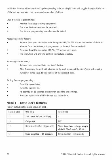
NOTE: For features with more than 2 options pressing Unlock mulitple times will toggle through all the rest
of the settings and emit the corresponding number of chirps.
Once a feature is programmed:
• Anotherfeature(s)canbeprogrammed.
• Theotherfeaturemenucanbeselected.
• Thefeatureprogrammingprocedurecanbeexited.
Accessing another feature:
• Release,thenpressandreleasetheintegratedLED/VALET®buttonthenumberoftimesto
advance from the feature just programmed to the next feature desired.
• Pressandhold the integrated LED/VALET® button once more.
• Thesiren/hornwillchirptoconfirmthefeatureselected.
Accessing another menu:
• Release,thenpressandholdtheValet®button.
• After3-seconds,theunitwilladvancetothenextmenuandthesiren/hornwillsounda
number of times equal to the number of the selected menu.
Exiting feature programming :
• Closetheopeneddoor
• TurnstheignitionOn.
• Noactivityfor15secondsexceptwhenselectingthesettings.
• PressandreleasetheVALET®buttontoomanytimes.
Menu 1 – Basic user’s features
Factory default settings are shown in bold.
Feature Step One chirp Two chirps
1-1 ZAP (reset default settings) -
1-2 Chirps ON OFF
1-3 Horn function(full trigger only) Siren function - chirp length (20mS, 30mS, 40mS, 50mS)
1-4 Siren duration - 30 seconds Siren duration - 60 seconds

23
Menu 2 – Advanced user’s featuresFactory default settings are shown in bold
Feature Step One chirp Two chirps
2-1 Light confirmation ON OFF
2-2 Parking light supervision ON Parking light supervision OFF
2-3 Light Output (parking lights) Light Output (turn signal)
2-4 Automatic re-arming On (60S) Automatic re-arming OFF
Menu 3 - Installer featuresFactory default settings are shown in bold
F e a t u r e Step
One chirp Two chirps
3-1 Nuisance Prevention® Circuity (ON)
Nuisance Prevention® Circuity OFF
3-2 Arm function (Arm Only) Arm function (Grouped Multi-level Arming- zones 2 & 4, Panic, AUX Ch )
3-3 Progressive door trigger Instant door trigger
3-4 One-time VALET® ON One-time VALET® OFF
3-5 Ground When Armed in VALET® (On)
Ground When Armed in VALET® (Off)
Bitwriter featuresFactory default settings are shown in bold
Feature Description
Siren duration 1-180 seconds (30 seconds)
Feature programming(unlocked) Feature programming (locked)
VALET® Code 1 to 5 (Default 1)
ZAP Reset all to default

© 2007 Directed Electronics—all rights reserved24
Features descriptionMenu 1 – Basic User’s Features
1-1 ZAP (Reset all features to default): This setting will reset all the features to factory default.
1-2 CHIRPS ON/OFF: This setting controls the systems arming & disarming chirps.
•ChirpsON(default):thesystemwillemitchirpswhenarminganddisarming.
•ChirpsOFF:thesystemwillNOTemitchirpswhenarminganddisarming.
1-3 HORN FUNCTION (FULL ALARM ONLY)/SIREN FUNCTION (20mS, 30mS, 40mS, and 50mS): This setting
controls if the output used by the alarm when fully triggered is the horn or the siren (in the last case dif-
ferent timing options for chirps can be selected).
1-4 SIREN DURATION 30/60 SECONDS: This setting changes the siren output from 30 seconds to 60 seconds
duration when in the panic mode and when the system is fully triggered. The siren duration can also be
programmed from 1-180 seconds in 1 second increments using the Bitwriter®.
Menu 2 – Advanced user’s features
2-1 LIGHT FLASH CONFIRMATION ON/ OFF: This setting control the light flash confirmation of the security
system on arming or disarming. When set ON, the security system will control the light confirmation of
arming/disarming of the vehicle. When set OFF, the security system will not control the lights confirmation
when arming/disarming the vehicle (the original confirmation light of the vehicles will be the only one
present on arming/disarming). Note: When (-) input blue/white status shunt is active, the parking lights
flash in case it is used for remote start.
2-2 PARKING LIGHT SUPERVISION ON/OFF: When set ON the parking lights will illuminate for 30-seconds
after disarming the system, or turning off the ignition. The parking lights will be switch OFF during this
time if the system is armed again or the ignition becomes ON.
2-3 LIGHT OUTPUT (PARKING LIGHTS/TURN SIGNAL): This settings control whether the parking lights or
turn signal will be used while the system is triggered or as confirmation lights.
2-4 AUTOMATIC RE-ARMING OFF/ON (60S): This settings control whether the system will re-arm if no door
was opened after 60 seconds or not. This will not include locking of the doors or arming the original security
system (if present). When set ON, the system will arm only if Lock button is pressed. This option is ignored
if the vehicle has automatic rearming feature ON from the factory.

© 2007 Directed Electronics—all rights reserved 25
Menu #3 – Installer features
3-1 NUISANCE PREVENTION® CIRCUITRY (NPC®) ON/OFF: These settings control the number of times a sensor
can trigger the system within a given time period.
•NPCON (Default): In this setting any source (sensor or trunk switch) that triggers more than 3 times
within 1 hour period will be bypassed for a minimum of 1 hour. If within that 1 hour the systems see’s
the same source (sensor or trunk switch) trigger again it will not activate the siren/horn and will restart
the 1 hour timer.
NOTE: Door switches and the ignition switch are exempt to the description above.
•NPCOFF:Inthissettingthesensorswilltriggerrepeatedlyuntilthesystemisdisarmed.
3-2 ARM FUNCTION OFF-ARM ONLY/ (Grouped MULTI-LEVEL ARMING/PANIC/AUX CH): These settings
change the system ability to activate multi-level arming, panic or auxiliary channel while pressing the
Lock button.
•WhensetARMONLY,thesystemwillbere-armedatsuccessivepressesonlockbutton.
•WhensetPANIC,thesystemwillswitchonpanicfunctionwhiletheuserpresslockbuttonforthesecond
time. Panic will cease when arming/disarming with original remote.
•When programmed on AUX CH, the system will activate the auxiliary channel when pressing the Lock
button for the second time.
•WhenprogrammedonMulti-levelArming,thesystemwillactivatetheMulti-levelArmingfunctionwhen
pressing the Lock button for the second time.
NOTE: The second press must be between 3 to 7 seconds from first press.
Grouped multi-level arming
After arming, press the LOCK button again. The parking lights or turn signal will flash 3 times, the siren/
horn will chirp 3 times and all sensor warn-away and full alarm zones will be bypassed. All remaining zones
are still active (door, hood, trunk, and ignition).
Aux channel
After arming, press the LOCK button again. The security system will activate the auxiliary output (N1/3)
and will start bypass all sensor zones for 30 seconds. During the first 3 seconds the security system will
monitor the trunk status and/or N1/8 Blue/White– (-) Status input: If either input is active, the security
system will bypass all sensors and the trunk when open, and flash the parking lights. After the trunk is
closed the sensors will be bypassed for another 20 seconds.
WARNING! If the AUX CHANNEL option is used for Remote Start activation the following must be taken into consideration:- The Remote start status output of the remote start module has to be connected to the
N1/8 Blue/White - (-) Status input in order for ignition and sensors to be bypassed during remote start.

© 2007 Directed Electronics—all rights reserved26
After the Status input is deactivated, the system will bypass sensors for another 20 seconds and the
ignition for 5 seconds.
- During the remote start the module will flash the lights. - During the remote start, the unit will ignore any activation of the OEM remote start (if present) from
the OEM transmitter.
- In some vehicles such as Honda and Acura, the keyless entry remotes are inactive while the vehicle is
running. You have to use the key to enter the running vehicle if the system is install one of those vehicle.
Turning the key in the key cylinder will disarm the system. You can not shut down the remote start with
the OEM transmitter either.
3-3 PROGRESSIVE DOOR TRIGGER ON/OFF: These settings control the siren/horn output when the system is
set off by the door trigger input.
•PROGRESIVEDOORTRIGGERON (default): In this setting if the door is opened while the system is armed
the siren will chirp (the horn will honk) 10 times prior to the constant siren/horn output. This is still an
instant trigger and closing the door quickly will not stop the trigger sequence.
•PROGRESIVE DOOR TRIGGER OFF: In this setting if the door is opened while the
system is armed the siren/horn will emit a constant siren/horn output immediately.
3-4 ONE TIME VALET® ON/OFF: These settings allows the system to be switched to VALET® mode but only
until the next time the ignition is turned on.
•ON:VALET®modeisexiteverytimetheignitionisturnedon.
•OFF(default):VALET®modeisexitonlybyusingtheVALET®switch
3-5 GROUND WHEN ARMED IN VALET® ON/OFF: Provides On/Off programming for the Ground When Armed
wire output when locking the vehicle in VALET® mode.
Bitwriter Features
SIREN DURATION (1-180S): The Bitwriter® can adjust the siren duration setting anywhere from 1 second
to 180 seconds in length.
FEATURE PROGRAMMING (UNLOCKED/LOCKED):
•UNLOCKED (default): In this setting the features can be changed using the Valet switch and the vehicle
OEM transmitter.
•LOCKED: In this setting the features can not be changed using the Valet switch and the vehicle OEM
transmitter. If LOCKED, the unit will emit 1 long chirp when trying to enter feature programming.

© 2007 Directed Electronics—all rights reserved 27
VALET® CODE: These settings change the number of times the Valet switch must be pressed to disarm the
system without the transmitter.
•1 pulse (default): Setting is 1 pulse
•2-5pulses:Thesesettingswillmakeitmoredifficultforathieftodefeatthesystem.
ZAP FUNCTION This button will reset all the features to default.
VALET® Mode
To prevent the system from arming, the system can be determined to enter in VALET® mode. To enter or
exit VALET® mode, use the integrated LED/VALET® switch as follows:
Turn the Ignition On, then OFF.
Within 10 seconds, press and release the integrated LED/VALET® button. The LED will come on if you have
entered VALET® mode. To exit VALET® mode, repeat the steps above. The LED will turn Off when VALET®
mode is exited.

© 2007 Directed Electronics—all rights reserved28
Special Features
Iniltialization:
The Unit has an initialization procedure that verifies that the unit is properly connected to the CAN bus. You
have to connect the unit to the CAN bus and than power it up. It has to pass the initialization procedure to
function normally. After connecting the CAN bus and powering up, you have to switch on the ignition for
the procedure to be completed. Each time power is disconnected the initialization procedure starts again.
The LED will visually report the status of the initialization procedure.
LED Flashes Description
LED blinks three digits with 2 seconds break between digits
Firmware revision
LED ON for 5 seconds and stops Initialization failed. Remove power and retry
LED blinks shortly every 3 seconds Hardware initialization passed, waiting for igni-tion to be turned ON
LED blinking rapidly Power up initialization in process
LED ON for 2.5 seconds, then OFF for 2.5 seconds, then blinks shortly a number and stops
- error 1 = vehicle not recognized- error 2= newest firmware for the vehicle soft-ware (check the website for downloading new firmware)
LED OFF immediately after blinking rapidly Initialization passed and it enter normal opera-tion

© 2007 Directed Electronics—all rights reserved 29
Vehicle application chartsThe following charts lists all of the vehicles covered by each of the platforms as of 10-2007. Firmware
versions for various vehicle platforms are available through the Directed Vehicle Interface Program (VIP)
& Bootloader.
Note: Please visit www.xpresskit.com for online VIP detailed
installation instructions and troubleshooting guide.

© 2007 Directed Electronics—all rights reserved30
3901V Vehicle Application Chart - Fault Tolerant (a)CAN-OEM fault tolerant Make Brand Year Operates Parking Lights
Hood Switch available through CAN-BUS
VIN Code (Note*1)
VW
Caddy 2005 -2007 • • 2K
Touran 2003 -2007 • • 1T
Passat 1996 - 2005 • 3B
New Passat 2005 -2007 • • 3C
Jetta 2005 -2007 • • 1K
Touareg 2003 -2007 • • 7L
EOS 2006 -2007 • • 1F
Polo Mark IV 2002 - 2005 • • 9N
Polo Mark IVF 2005 -2007 • (only Turn Signal) • 9N3
Transporter 2004 -2007 • (only Turn Signal) • N/A
Porsche Cayenne 2003 -2007 • • 9P
Seat
Ibitza • (only Turn Signal)
Altea 2004 -2007 • • 5P
Toledo 2004 -2007 • • 5P
Leon 1999 -2007 • 1M
New Leon ? • • 1P
Cordoba 2002 -2007 • (only Turn Signal) • N/A
Skoda
Octavia Tour 1996 -2007 • 1U
Octavia II 2004 -2007 • • 1Z
Superb 2002-2007 • 3U
Fabia 1999 -2007 • N/A
New Fabia 2007 • (only Turn Signal) • N/A
Roomster 2006 -2007 • (only Turn Signal) • N/A
Audi
A3 2004 -2007 • • 8P
A4 2002 -2007 • • 8E
A4 Cabrio 2007 • • 8H
A6 2004 -2007 • • 4F
A6 Allroad 2007 • • 4F
Q7 2006 -2007 • • 4L
TT 2007 • • 8J
BMW
1 Series 2004 -2007 E81/E87
3 Series5 Series 2004 -2007 E60/E61
Idea 2004 -2007 N/A

© 2007 Directed Electronics—all rights reserved 31
3901V Vehicle Application Chart - Fault Tolerant (b)
Fiat
Grande Punto 2005 -2007 N/A
Punto 2003 -2007 N/A
Stilo 2001 -2007 N/A
Croma 2005 -2007 N/A
Ducato 2006 -2007 N/A
Doblo 2001 -2007 N/A
Alfa
159 2005 -2007 N/A
Brera 2005 -2007 N/A
147 2000 -2007 N/A
LanciaYpsilon 2003 -2007 N/A
Musa 2004 -2007 N/A
Peugeot307 2001 -2007 N/A
407 2004 -2007 N/A
Chrysler
300C 2005 -2007 • C3K/C3J
Sebring 2006 -2008 • C3L
Aspen 2007 • A8H
Pt Cruiser 2001 -2007 A4F
Dodge
Charger 2006 -2007 • B3K
Magnum 2005 -2007 • D4F
Durango 2004 -2007 • D4H
Dakota 2006 -2007 D7H
RAM 2006 -2007 D7H
Avenger 2006-2008 B3L
Caliber 2006 -2007 N/A
Jeep
Commander 2006 -2007 • J8H
Grand Cherokee 2005 -2007 • J4H
Compass 2006 -2007 J8F
Mercedes
A Classe 2004 -2007 • W169
B Classe 2005 -2007 • W245
C Classe 2000 -2007 • W203
E Classe 2003 -2007 • W211
NOTE*1For Audi/Seat/Skoda/Porsche/VW the two digits are the 7th and the 8th. For example: Audi A6 has xxxxxx4F.
For Chrysler/Dodge/Jeep the digits are the 2nd, the 3rd and the 4th. For example: Dodge Charger has xB3K.
For Mercedes the digits are the 2nd, the 5th, 6th and 7th. For example: Mercedes C Classe has Wxx203.

© 2007 Directed Electronics—all rights reserved32
3902V Vehicle Application Chart - Single Wire

© 2007 Directed Electronics—all rights reserved 33
3903V Vehicle Application Chart - High Speed

© 2007 Directed Electronics—all rights reserved34
Wiring quick reference guide
RED (+) 12VBLACK common
BLUE Mux zone 4GREEN Mux zone4
LIGHT GREEN-Single wire CAN bus
ORANGE / GREEN (BROWN/RED) / CAN bus wire (high)Fault Tolerant (High speed)
ORANGE / BROWN (BROWN/BLACK) /CAN bus wire (low) Fault Tolerant (High speed)
RED (+) 12V Constant powerBLACK(-) Chassis ground connectionRED/WHITE (-) 200mA Aux Ch output
BLUE(-) Instant trigger inputORANGE (-) Ground when armed outputWHITE (-) 200mA Light Flash outputBROWN (+) Siren output
BLUE/WHITE (-) Status input
BROWN/WHITE (-) 200mA Horn output

© 2007 Directed Electronics—all rights reserved 35

© 2007 Directed Electronics—all rights reserved36
Directed Electronics, Inc.
Vista, CA 92081
www.directed.com
© 2007 Directed Electronics, Inc. - All rights reserved
N3901V 2007-09


![Untitled-2 [suntracbatteries.com]suntracbatteries.com/suntrac.pdf · capacity 12v 20ah 12v 40ah 12v 60ah 12v b40ah 12v b60ah 12v b80ah 12v biooah 12v 80ah 12v iooah 12v 130ah 12v](https://img.dokumen.tips/doc/110x75/603efb7aa12c32391f5484d1/untitled-2-capacity-12v-20ah-12v-40ah-12v-60ah-12v-b40ah-12v-b60ah-12v-b80ah.jpg)