Embed Size (px)
Citation preview
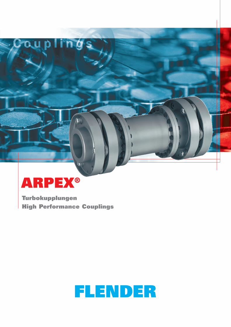
ARPEX®
TurbokupplungenHigh Performance Couplings
K 4312 DE /EN2
ARPEXTurbokupplungen High Performance CouplingsCharakteristische Merkmale Characteristic Features
ARPEX-Turbokupplungen wurden f¸r den Einsatz in sehranspruchsvollen Antriebssystemen der Energietechnik,derpetrochemischen Industrie und inSchiffsantriebenent-wickelt.ARPEX-Turbokupplungen kˆnnen in allen hochtourigenAnwendungen eingesetzt werden, wo eine zuverl‰ssigeDrehmoment¸bertragungbeigleichzeitigerWellenverlage-rung verlangt wird.
Einsatzgebiete" Generatoranlagen" Gas- und Dampfturbinen" Turbokompressoren" Kesselspeisepumpen" Schiffsantriebe" Pr¸fst‰nde
Vorteile" Keine Schmierung erforderlich" Lamellenpakete mit patentierter, formschl¸ssiger Ko-
nusverschraubung. Daraus resultiert eine spielfreieDrehmoment¸bertragung.
" Erf¸llt die Anforderungen der API 671" Einfache Montage durch werkseitig montierte Halb-
kupplungen bzw. ‹bertragungseinheiten" Kompakte, gewichtsoptimierte Ausf¸hrung" Geringe R¸ckstellkr‰fte" Hohe Wuchtg¸te
Leistungsbereiche
Baureihe ART-6Kupplungs--Nenndrehmoment TKN = 1.000 bis 42.000 Nm6-eck LamellenpaketZul. Winkelversatz = 0,35!
Die Baureihe ART-6 ermˆglicht die grˆflten radialen und axialen Wellenver-s‰tze aufgrund der hohen Flexibilit‰t des 6-eck Lamellenpakets. Somit ei-gnet sich diese Baureihe ideal f¸r Anwendungen mit groflenW‰rmeausdeh-nungen (Axialversatz), beiminimal auf die Lager wirkendenR¸ckstellkr‰ften.
Baureihe ART-8Kupplungs--Nenndrehmoment TKN = 5.700 bis 416.000 Nm8-eck LamellenpaketZul. Winkelversatz = 0,25!
Die Baureihe ART-8 kombiniert hohe Drehmomentkapazit‰t mit hoher Flexi-bilit‰t. Deshalb wird diese Baureihe f¸r diemeisten hochtourigen Anwendun-gen bevorzugt.
Baureihe ART-10Kupplungs--Nenndrehmoment TKN = 26.800 bis 535.000 Nm10-eck LamellenpaketZul. Winkelversatz = 0,16!
DieBaureiheART-10ermˆglicht die grˆflteDrehmomentkapazit‰t bei kleine-ren Wellenverlagerungen. Deshalb wird diese Baureihe bei Anwendungenmit hohen Stoflmomenten und kleineren Verlagerungsanforderungen einge-setzt.
ARPEX-High Performance Couplings were designed forvery demanding drive system applications in the energyand petrochemical industry and marine propulsion drives.
ARPEX-High Performance Couplings are used for all highspeed purposes where reliable power transmission is re-quired even with unavoidable shaft misalignment.
Applications" Generator sets" Gas and steam turbines" Turbo compressor machinery" Boiler feed pumps" Marine propulsion drives" Development test stands
Advantages" No lubrication required" Disc packs with patented, form closed conical bolting.
This results in a backlash-free torque-transmission.
" Meets the requirements of API 671" Easy to install with factory assembled half couplings
and transmission units" Reduced moment configuration" Low restoring forces" High balancing quality
Ranges of capacity
Series ART-6Coupling torque TKN = 1.000 to 42.000 NmHexagonal disc packPerm. angular misalignment = 0,35!
The series ART--6 allows the most radial and axial shaft misalignment due tothe high flexibility of the hexagonal disc design. Thus this series is ideal forapplications where high thermal growth (axial offset) occur with aminimumofrestoring forces on bearings.
Series ART-8Coupling torque TKN = 5.700 to 416.000 NmOctagonal disc packPerm. angular misalignment = 0,25!
The series ART--8 combines high torque capacity with high flexibility. There-fore this series is the preferred one for the most high speed applications.
Series ART-10Coupling torque TKN = 26.800 to 535.000 NmDecagonal disc packPerm. angular misalignment = 0,16!
Theseries ART--10 allows higher torquecapacity with smaller shaftmisalign-ment. Thus this series is used for application with high peak torques andlower misalignment requirements.

K 4312 DE / EN 3
ARPEXTurbokupplungen High Performance CouplingsKupplungsbauarten Coupling designs
Bauarten der ARPEX-Turbokupplungen
ARPEX-Turbokupplungen sind in zwei Standard--Bauarten lieferbar. Diekompakte Ausf¸hrung BVB ergibt kleinstmˆgliche Momentbelastungen derAnschluflwellen. Ausf¸hrung MHM ermˆglicht grˆflere Wellendurchmesser.Flanschanschl¸sse sind ebenfalls nach Kundenanforderung lieferbar.Die Kupplungen wurden entwickelt, um gleichzeitig eine Optimierung vonGewicht und Drehmomentkapazit‰t zu erreichen.
Die f¸r die Turbokupplung verwendetenWerkstoffe wurden sorgf‰ltig ausge-w‰hlt. Naben, Flansche, H¸lsen und Lamellenpaketverschraubungen sindaus hochwertigem Verg¸tungsstahl. Die Lamellen, welche hohe Flexibilit‰tmit hoher Drehmomentkapazit‰t verbinden, sind aus rostfreiem Federstahl.Die taillierte Form der Lamellen ermˆglicht eine gleichm‰flige Spannungs-verteilung. Die R¸ckstellkr‰fte auf die Lager der gekoppelten Maschinenwerden minimal gehalten.
Die Lamellenpaketverschraubung ist eine patentierte Konusausf¸hrung(mehr Details auf Seite 5). Dadurch ist die Drehmoment¸bertragung form-schl¸ssig.
Die Zwischenh¸lsen sind ohne Versetzen der An- und Abtriebswelle radialausbaubar.
Die Kupplungsausf¸hrung erf¸llt alle Anforderungen der API 671. Die Werk-stoffe entsprechen jedoch den europ‰ischen Normen; Schrauben und Mut-tern haben metrische Gewinde.
ARPEX-High Performance Coupling Designs
The ARPEX-High Performance Coupling is available in two standard types.The compact configuration of type BVB results in a reduced moments coupl-ing. Type MHM allows larger shaft diameters.According to the requirements of the customer flange connections are avail-able too.Thecouplingsweredesigned togiveanoptimumweight andhigh loadcapac-ity at the same time.
The materials used for the high performance coupling have been carefullychosen. Hubs, flanges, spacers and disc pack boltings are from heat-treatedalloy steel. The discs, which provide high flexibility with high torque capacity,are from stainless spring steel. The scalloped shape of the discs leads to auniform stress distribution. The reaction forces on the bearings of the con-nected machines are kept to a minimum.
The disc pack bolting is a patented conical design (more details on page 5).Therefore the torque is transmitted form-closed.
The spacers can be removed radially without shifting connected machines.
The coupling designmeets all requirements of the API 671. However thema-terials refer to European standards; the nuts and bolts have metric threads.
Ausf¸hrung/Type BVB
" Kompakte, gewichtsoptimierte Ausf¸hrungReduced moment configuration
" Ventilationsarme Ausf¸hrungReduced windage design
" Variable H¸lsenl‰ngeVariable spacer length
" Ideal f¸r Antriebe Turbine - KompressorIdeal on turbine compressor drives
" Einfache MontageEasy to install
" Naben f¸r grofle BohrungsdurchmesserHubs for large bore capacity
" Ventilationsarme Ausf¸hrungReduced windage design
" Variable H¸lsenl‰ngeVariable spacer length
" Ideal f¸r E-Motoren oder GeneratorantriebeIdeal on electric motor or generator drives
" Einfache MontageEasy to install
Ausf¸hrung/Type MHM
Flanschausf¸hrung/flange design
" Flanschausf¸hrungen der Typen BVB undMHM sind alternativ lieferbarFlange design of type BVB and MHM isavailable alternative
" Flanschanschluflmafle werden nach Kunde-nanforderung ausgelegtFlange dimensions will be lay out acc. to thecustomers requirements
K 4312 DE / EN4
ARPEXTurbokupplungen High Performance CouplingsLamellen, FEM discs, FEM
LamellenDie Funktionsweise der ARPEX-Turbokupplung basiert auf den flexiblen La-mellenpaketen. Die Lamellenpakete verbinden eine hohe Flexibilit‰t mitgleichzeitig hoher Drehmomentkapazit‰t. Somit wird eine zuverl‰ssigeDrehmoment¸bertragung auch bei unvermeidlichen Wellenverlagerungengew‰hrleistet.Die Lamellen bestehen aus hartgewalztem Federstahl. Das Material ist rost-frei und besitzt eine extrem hohe Zugfestigkeit.Durch den Einsatz von sehr d¸nnen Einzellamellen treten beiWellenverlage-rungen vergleichsweise geringe R¸ckstellkr‰fte auf, was sich positiv auf dieLagerlebensdauer der gekoppelten Maschinen auswirkt.Die taillierte Ausf¸hrung der Lamellen ermˆglicht eine gleichm‰flige Span-nungsverteilung in den Lamellen. Zus‰tzlich wird das Gewicht und das Mas-sentr‰gheitsmoment verringert.Die Lamellen sindmit einem hohenMafl an Betriebssicherheit f¸r eine unbe-grenzte Lebensdauer ausgelegt.
DiscsThe way of function of the ARPEX-High Performance Coupling is based onthe flexible disc packs. The disc packs combine high flexibility with hightorque capacity at the same time. Thus a reliable power transmission evenwith unavoidable shaft misalignments is guaranteed.The discs consist of hard-rolled spring steel. The material is stainless andhas a extreme high tensile strength.Using flexible, thin discs results in very low restoring forces, what affectspositively the bearing operating life of the coupled machines.The scalloped design of the discs make a constant stress distribution poss-ible. Additional the weight and the moment of inertia is reduced.The discs are designed for unlimited service life with a high degree of oper-ational safety.
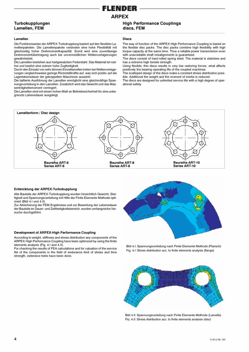
Lamellenform / Disc design
Baureihe ART-6Series ART-6
Baureihe ART-8Series ART-8
Baureihe ART-10Series ART-10
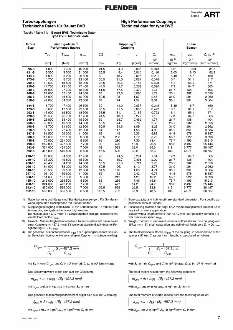
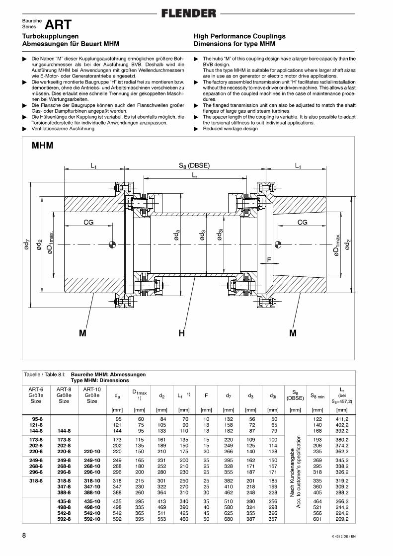
Entwicklung der ARPEX-TurbokupplungAlle Bauteile der ARPEX-Turbokupplung wurden hinsichtlich Gewicht, Stei-figkeit und Spannungsverteilung mit Hilfe der Finite Elemente Methode opti-miert (Bild 4.I und 4.II).Zur Absicherung der FEM-Ergebnisse und zur Bewertung der Lebensdauerder Bauteile im Dauer- und Zeitfestigkeitsbereich, wurden umfangreicheVer-suche durchgef¸hrt.
Development of ARPEX-High Performance CouplingAccording to weight, stiffness and stress distribution any components of theARPEX-High Performance Coupling have been optimized by using the finiteelements analysis (Fig. 4.I and 4.II).For checking the results of FEA calculations and for valuation of the servicelife of the components in the field of endurance limit of stress and timestrength, extensive tests have been done.
Bild 4.I: Spannungsverteilung nach Finite Elemente Methode (Flansch)Fig. 4.I: Stress distribution acc. to finite elements analysis (flange)
Bild 4.II: Spannungsverteilung nach Finite Elemente Methode (Lamelle)Fig. 4.II: Stress distribution acc. to finite elements analysis (disc)

K 4312 DE / EN 5
ARPEXTurbokupplungen High Performance CouplingsKonische Lamellenpaketverschraubung Conical disc pack bolting
Patentierte Konusverschraubung als Lamellenpaketverschrau-bung
Patented conical bolting as disc pack bolting
Bild 5.I: Aufbau KonusverschraubungFig. 5.I: Design of conical bolting
vor demAnziehenderVerschraubungbefore tighten the bolting
Mutter
Flansch Lamellen Flansch
KonusbolzenKonush¸lse
flange discs flange
nut conical boltconical bushing
nachdemAnziehender Verschraubungafter tighten the bolting
Vorteile
" Formschl¸ssige Drehmoment¸bertragung:Der entscheidene Vorteil der Konusverschraubung gegen¸ber der Verwen-dung vonPaflschrauben ist der echteFormschlufl, der in der Lamellenpaket-verschraubung entsteht. Der Formschlufl wird durch die konische Ausf¸h-rung der Verschraubung erreicht.
" Wirkungsweise:Durch Anziehen der Mutter wird der Konusbolzen in die Konush¸lse gezo-gen, wodurch die H¸lse aufgeweitet wird. Damit ist eine formschl¸ssige Ver-bindung sowohl zwischen Konusbolzen undH¸lse als auch zwischenH¸lse,Flansch und Lamellen garantiert.Dies steht im Gegensatz zu typischen Lamellenpaketverschraubungen, diedas Drehmoment reibschl¸ssig ¸bertragen.
" Geringeres Gewicht:Die Konusverschraubung hat Gewichts- und Massentr‰gheitsvorteile vergli-chen mit einer Paflschraubenverbindung, die die gleicheDrehmomentkapa-zit‰t hat.
" Zentrierung:Die Zentriergenauigkeit durch Verwendung der Konusverschraubung ist au-flerordentlich hoch. Dies ermˆglicht eine hohe Wuchtg¸te.
" Material:Alle Einzelteile der Konusverschraubung sind aus hochwertigem Verg¸-tungsstahl gefertigt.
Advantages
" Form-closed torque transmission:Thedecisivedifference of the conical bolting comparedwith fittingbolts is thereal form-closed connection, which occurs in the disc pack bolting. The form-closed connection is achieved by the conical design of the bolting.
" Operation:By tightening the nut the conical bolt is pulled into the conical bushing and thebushing is widen. Therefore a form--closed connection both between conicalbolt and bushing and between bushing, flange and discs is guaranteed.This is a contrast to typical disc pack boltings, which transmit the torque ten-sionally connected.
" Lower weight:The conical bolting has weight and inertia advantages compared with fittedboltings, which have the same torque capacity.
" Centering:The precision of centering by using the conical bolting is extraordinary high.This facilitates a high balancing quality.
" Material:Each component of the conical bolting is manufactured from high-qualityalloy steel.

Acc
.tocu
stom
eríssp
ecifica
tion
Nac
hKun
dena
ngab
e
K 4312 DE / EN6
BaureiheSeries ARTTurbokupplungen High Performance CouplingsAbmessungen f¸r Bauart BVB Dimensions for type BVB
" Die Anordnung der Kupplungsbauteile ermˆglicht eine geringere Mo-mentbelastungderAnschluflwellen; ideal geeignet f¸rAntriebe Turbine -Kompressor.
" Die Halbkupplungen ìBî sind werkseitig montiert. Die separat ein- bzw.ausbaubare H¸lse ìVî ist radial frei zumontieren, ohne die Antriebs- undAbtriebsmaschinen verschieben zu m¸ssen. Dies ermˆglicht einschnelles Trennen der gekoppelten Maschinen bei Wartungsarbeiten.
" Die H¸lsenl‰nge der Kupplung ist variabel. Es ist ebenfalls mˆglich, dieTorsionsfedersteife f¸r individuelle Anwendungen anzupassen.
" Ventilationsarme Ausf¸hrung
" The arrangement of the coupling parts make it possible to get a lowerload on the connection shafts; ideally suited to turbine compressordrives.
" The half couplings ìBî are factory assembled. The separate detachablespacer ìVî facilitates radial installation without the necessity to movedriver or drivenmachine. This allows a fast separation of the coupledma-chines in the case of maintenance procedures.
" The spacer length of the coupling is variable. It is also possible to adaptthe torsional stiffness to suit individual applications.
" Reduced windage design
BVB
B V B
CG CG
¯d a¯d 2
¯D1max
.
L1L1 S8 (DBSE)
¯d 6
¯d 5
¯d 5
i
L2 L2
¯d a
¯d 2
¯D1ma x
.
Lr
Tabelle / Table 6.I: Bauart BVB: AbmessungenType BVB: Dimensions
ART-6GrˆfleSize
ART-8GrˆfleSize
ART-10GrˆfleSize
daD1max
1)d2
L11)
L2 d5 d5i d6S8
(DBSE) S8 min
Lr(bei
S8=457,2)
[mm] [mm] [mm] [mm] [mm] [mm] [mm] [mm] [mm] [mm] [mm]
95-6121-6144-6 144-8
95121144
354555
496377
354555
7887
105
617990
567382
94112133
131129155
481,2492,2502,2
173-6202-6220-6
173-8202-8220-8 220-10
173202220
708090
98112126
708095
118125142
112127145
104117135
155170200
151145166
520,2534,2552,2
249-6268-6296-6
249-8268-8296-8
249-10268-10296-10
249268296
105110120
147154168
105115125
160179190
165182200
154170187
220238256
182208210
555,2568,2576,2
318-6 318-8347-8388-8
318-10347-10388-10
318347388
130140160
182196224
135145165
200215240
210235260
196219241
278303335
220230260
589,2599,2618,2
435-8498-8542-8592-8
435-10498-10542-10592-10
435498542592
180210230250
252294322350
185215240260
277312337357
295335370400
274311343372
370415464494
294304324324
636,2674,2704,2729,2
K 4312 DE / EN 7
BaureiheSeries ART
Turbokupplungen High Performance CouplingsTechnische Daten f¸r Bauart BVB Technical data for type BVB
Tabelle / Table 7.I: Bauart BVB: Technische DatenType BVB: Technical data
GrˆfleSize
Leistungsdaten 2)
Performance figuresKupplung 3)
CouplingH¸lseSpacer
TKN TPeak nmax CG m J Ct mS8 JS8 Ct S84)
[Nm] [Nm] [min--1] [mm] [kg] [kgm2]∑106
[Nm/rad]∑10--3
[kg/mm]∑10--6
[kgm2/mm]∑106
[Nm∑mm/rad]
95-6121-6144-6173-6202-6220-6249-6268-6296-6318-6
1 0002 3004 0006 700
10 60014 70021 00027 00035 00042 000
1 3003 0005 2008 700
13 80019 10027 30035 10045 50054 600
40 20031 60026 50022 10018 90017 40015 30014 30012 90012 000
21,525,53035,538,544,551,55560,564
4,98,4
13,721,030,442,757,572,893
114
0,0060,0160,0360,0810,1550,2690,4700,6901,071,51
0,0480,1100,2010,3780,6230,8961,341,792,433,02
3,615,638,49
10,715,117,321,726,131,035,1
3,098,13
15,731,156,184,7
138202291361
31,582,9
160317571863
1 4042 0582 9623 684
144-8173-8202-8220-8249-8268-8296-8318-8347-8388-8435-8498-8542-8592-8
5 7009 600
15 00020 50029 50038 30049 70059 50081 500
117 000170 000252 000334 000416 000
7 40012 50019 50026 70038 40049 80064 60077 400
106 000152 100221 000327 600434 200540 800
26 50022 10018 90017 40015 30014 30012 90012 00011 0009 8008 8007 7007 0006 500
3035,538,544,55255,560,5646978,58899
109116,5
14,021,531,143,658,77494,6
117149208290420559690
0,0370,0830,1590,2770,4820,7061,091,562,364,127,30
13,922,032,2
0,2480,4720,7921,161,772,383,284,095,838,73
13,420,828,336,3
8,4910,715,117,321,726,131,035,144,858,773,795,6
119133
15,731,156,184,7
138202291361578922
1 4932 4973 7774 971
160317571863
1 4042 0582 9623 6845 8879 396
15 21325 44338 48750 657
220-10249-10268-10296-10318-10347-10388-10435-10498-10542-10592-10
26 80038 30049 40064 00076 500
105 100151 800219 600324 800430 000535 000
34 80049 80064 20083 20099 500
136 600197 300285 500422 200559 000695 500
17 40015 30014 30012 90012 00011 0009 8008 8007 7007 0006 500
455255,560,564,569798899
109,5116,5
44,559,775,396,1
120152212295427569702
0,2840,4930,7211,121,602,424,237,46
14,222,532,9
1,312,022,733,774,716,78
10,215,824,733,843,5
17,321,726,131,035,144,858,773,795,6
119133
84,7138202291361578922
1 4932 4973 7774 971
8631 4042 0582 9623 6845 8879 396
15 21325 44338 48750 657
1) Nabenbohrung und -l‰nge sind Standardabmessungen. F¸r Sonderan-wendungen bitte R¸cksprache mit Flender halten.
2) Kupplungsauslegung siehe Seite 12. EinBetriebsfaktor 1,5mufl f¸r jedeAnwendung wenigstens ber¸cksichtigt werden.Bei H¸lsen ¸ber 457,2 mm (18î) L‰nge ergeben sich ggf. reduziertema-ximale Drehzahlen nmax.
3) Gewicht, Massentr‰gheitsmoment und Torsionsfedersteife basierenaufeinerKupplungmit 457,2mm (18î)Wellenabstandund zylindrischerFer-tigbohrung D1 = D1 max.
4) DiegesamteTorsionsfedersteifeCt ges der Kupplungberechnet sich, un-terBer¸cksichtigungderH¸lsensteifigkeit CtS8 je 1mmL‰nge, wie folgt:
Ct ges !1
1Ct
"S8#457,2 mm
Ct S8
mit S8 in mm; Ct ges und Ct in 106 Nm/rad; Ct S8 in 106 Nm∑mm/rad
Das Gesamtgewicht ergibt sich aus der Gleichung:
mges = m + mS8 ∑ (S8 --457,2 mm)
mit mges und m in kg; mS8 in kg/mm; S8 in mm
Das gesamte Massentr‰gheitsmoment ergibt sich aus der Gleichung:
Jges = J + JS8 ∑ (S8 --457,2 mm)
mit Jges und J in kgm2; JS8 in kgm2/mm; S8 in mm
1) Bore capacity and hub length are standard dimension. For specific ap-plications consult Flender.
2) For coupling selection seepage 12. Aminimumapplication factor of 1.5 isrequired on every application.Spacer with a length of more than 457,2 mm (18î) possibly come to a lo-wer maximum speed nmax.
3) Weight, moment of inertia and torsional stiffness based ona couplingwith457,2 mm (18î) shaft separation and cylindrical finish bore D1 = D1 max.
4) The total torsional stiffness Ct ges of the coupling, in consideration of thespacer stiffness Ct S8 per 1 mm length, is calculated as follows:
Ct ges !1
1Ct
"S8#457,2 mm
Ct S8
with S8 in mm; Ct ges and Ct in 106 Nm/rad; Ct S8 in 106 Nm∑mm/rad
The total weight results from the following equation:
mges =m + mS8 ∑ (S8 --457,2 mm)
with mges and m in kg; mS8 in kg/mm; S8 in mm
The total moment of inertia results from the following equation:
Jges = J + JS8 ∑ (S8 --457,2 mm)
with Jges and J in kgm2; JS8 in kgm2/mm; S8 in mm
Acc
.tocu
stom
eríssp
ecifica
tion
Nac
hKun
dena
ngab
e
K 4312 DE / EN8
BaureiheSeries ARTTurbokupplungen High Performance CouplingsAbmessungen f¸r Bauart MHM Dimensions for type MHM
" Die Naben ìMî dieser Kupplungsausf¸hrung ermˆglichen grˆflere Boh-rungsdurchmesser als bei der Ausf¸hrung BVB. Deshalb wird dieAusf¸hrung MHM bei Anwendungen mit groflen Wellendurchmessernwie E-Motor- oder Generatorantriebe eingesetzt.
" Die werkseitig montierte Baugruppe ìHî ist radial frei zu montieren bzw.demontieren, ohne die Antriebs- und Arbeitsmaschinen verschieben zum¸ssen. Dies erlaubt eine schnelle Trennung der gekoppelten Maschi-nen bei Wartungsarbeiten.
" Die Flansche der Baugruppe kˆnnen auch den Flanschwellen groflerGas- oder Dampfturbinen angepaflt werden.
" Die H¸lsenl‰nge der Kupplung ist variabel. Es ist ebenfalls mˆglich, dieTorsionsfedersteife f¸r individuelle Anwendungen anzupassen.
" Ventilationsarme Ausf¸hrung
" The hubs ìMî of this coupling design have a larger bore capacity than theBVB design.Thus the type MHM is suitable for applications where larger shaft sizesare in use as on generator or electric motor drive applications.
" The factory assembled transmission unit ìHî facilitates radial installationwithout thenecessity tomovedriver or drivenmachine. This allows a fastseparation of the coupled machines in the case of maintenance proce-dures.
" The flanged transmission unit can also be adjusted to match the shaftflanges of large gas and steam turbines.
" The spacer length of the coupling is variable. It is also possible to adaptthe torsional stiffness to suit individual applications.
" Reduced windage design
MHM
S8 (DBSE)
F
L1
M H M
CGCG
¯D1m
ax.
¯d 2
¯d a
¯d 3
¯d 3
i
¯D1m
ax.
¯d 2¯d 7
L1Lr
Tabelle / Table 8.I: Baureihe MHM: AbmessungenType MHM: Dimensions
ART-6GrˆfleSize
ART-8GrˆfleSize
ART-10GrˆfleSize
daD1max
1) d2 L1 1) F d7 d3 d3iS8
(DBSE) S8 min
Lr(bei
S8=457,2)
[mm] [mm] [mm] [mm] [mm] [mm] [mm] [mm] [mm] [mm] [mm]
95-6121-6144-6 144-8
95121144
607595
84105133
7090
110
101313
132158182
567287
506579
122140168
411,2402,2392,2
173-6202-6220-6
173-8202-8220-8 220-10
173202220
115135150
161189210
135150175
151520
220249266
109125140
100114128
193206235
380,2374,2362,2
249-6268-6296-6
249-8268-8296-8
249-10268-10296-10
249268296
165180200
231252280
200210230
252525
295328355
162171187
150157171
269295318
345,2338,2326,2
318-6 318-8347-8388-8
318-10347-10388-10
318347388
215230260
301322364
250270310
252530
382410462
201218248
185199228
335360405
319,2309,2288,2
435-8498-8542-8592-8
435-10498-10542-10592-10
435498542592
295335365395
413469511553
340390425460
35404550
510580625680
280324355387
256298326357
464521566601
266,2244,2224,2209,2
K 4312 DE / EN 9
BaureiheSeries ART
Turbokupplungen High Performance CouplingsTechnische Daten f¸r Bauart MHM Technical data for type MHM
Tabelle / Table 9.I: Bauart MHM: Technische DatenType MHM: Technical data
GrˆfleSize
Leistungsdaten 2)
Performance figuresKupplung 3)
CouplingH¸lseSpacer
TKN TPeak nmax CG m J Ct mS8 JS8 Ct S84)
[Nm] [Nm] [min--1] [mm] [kg] [kgm2]∑106
[Nm/rad]∑10--3
[kg/mm]∑10--6
[kgm2/mm]∑106
[Nm∑mm/rad]
95-6121-6144-6173-6202-6220-6249-6268-6296-6318-6
1 0002 3004 0006 700
10 60014 70021 00027 00035 00042 000
1 3003 0005 2008 700
13 80019 10027 30035 10045 50054 600
28 90024 20021 00017 40015 30014 40012 90011 60010 80010 000
668193,5111121,5137155,5166179191,5
8,414,423,640,15979,2
107140182224
0,0140,0360,0840,2140,4160,6711,131,782,804,01
0,0500,1180,2290,4680,8061,171,762,343,254,09
3,925,918,19
11,616,219,823,128,335,338,1
2,766,95
14,131,758,089,2
141191283355
28,270,9
144323591909
1 4331 9442 8893 620
144-8173-8202-8220-8249-8268-8296-8318-8347-8388-8435-8498-8542-8592-8
5 7009 600
15 00020 50029 50038 30049 70059 50081 500
117 000170 000252 000334 000416 000
7 40012 50019 50026 70038 40049 80064 60077 400
106 000152 100221 000327 600434 200540 800
21 00017 40015 30014 40012 90011 60010 80010 0009 3008 3007 5006 6006 1005 600
94111,5122138156,5166,5180193210237,5260,5295,5320344,5
23,940,559,480
108141184227283406566828
1 0551 331
0,0850,2160,4200,6781,141,802,834,065,82
10,718,936,054,280,5
0,2730,5781,0191,512,333,124,445,617,98
12,219,732,043,758,5
8,1911,616,219,823,128,335,338,148,858,779,399,7
122138
14,131,758,089,2
141191283355532833
1 4272 4153 5364 769
144323591909
1 4331 9442 8893 6205 4228 485
14 54224 61336 03248 597
220-10249-10268-10296-10318-10347-10388-10435-10498-10542-10592-10
26 80038 30049 40064 00076 500
105 100151 800219 600324 800430 000535 000
34 80049 80064 20083 20099 500
136 600197 300285 500422 200559 000695 500
14 40012 90011 60010 80010 0009 3008 3007 5006 6006 1005 600
139157,5167,5181194211239262297,5322346,5
80,6109142186229286409572836
1 0651 342
0,6841,151,822,864,115,88
10,819,136,454,781,2
1,712,673,585,166,549,35
14,523,839,354,373,6
19,823,128,335,338,148,858,779,399,7
122138
89,2141191283355532833
1 4272 4153 5364 769
9091 4331 9442 8893 6205 4228 485
14 54224 61336 03248 597
1) Nabenbohrung und-l‰nge sind Standardabmessungen. F¸r Sonderan-wendungen bitte R¸cksprache mit Flender halten.
2) Kupplungsauslegung siehe Seite 12. EinBetriebsfaktor 1,5mufl f¸r jedeAnwendung wenigstens ber¸cksichtigt werden.Bei H¸lsen ¸ber 457,2 mm (18î) L‰nge ergeben sich ggf. reduziertema-ximale Drehzahlen nmax.
3) Gewicht, Massentr‰gheitsmoment und Torsionsfedersteife basierenaufeinerKupplungmit 457,2mm (18î)Wellenabstandund zylindrischerFer-tigbohrung D1 = D1 max.
4) DiegesamteTorsionsfedersteifeCt ges der Kupplungberechnet sich, un-terBer¸cksichtigungderH¸lsensteifigkeit CtS8 je 1mmL‰nge, wie folgt:
Ct ges !1
1Ct
"S8#457,2 mm
Ct S8
mit S8 in mm; Ct ges und Ct in 106 Nm/rad; Ct S8 in 106 Nm∑mm/rad
Das Gesamtgewicht ergibt sich aus der Gleichung:
mges = m + mS8 ∑ (S8 --457,2 mm)
mit mges und m in kg; mS8 in kg/mm; S8 in mm
Das gesamte Massentr‰gheitsmoment ergibt sich aus der Gleichung:
Jges = J + JS8 ∑ (S8 --457,2 mm)
mit Jges und J in kgm2; JS8 in kgm2/mm; S8 in mm
1) Bore capacity and hub length are standard dimension. For specific ap-plications consult Flender.
2) For coupling selection seepage 12. Aminimumapplication factor of 1.5 isrequired on every application.Spacer with a length of more than 457,2 mm (18î) possibly come to a lo-wer maximum speed nmax.
3) Weight, moment of inertia and torsional stiffness based ona couplingwith457,2 mm (18î) shaft separation and cylindrical finish bore D1 = D1 max.
4) The total torsional stiffness Ct ges of the coupling, in consideration of thespacer stiffness Ct S8 per 1 mm length, is calculated as follows:
Ct ges !1
1Ct
"S8#457,2 mm
Ct S8
with S8 in mm; Ct ges and Ct in 106 Nm/rad; Ct S8 in 106 Nm∑mm/rad
The total weight results from the following equation:
mges = m + mS8 ∑ (S8 --457,2 mm)
with mges and m in kg; mS8 in kg/mm; S8 in mm
The total moment of inertia results from the following equation:
Jges = J + JS8 ∑ (S8 --457,2 mm)
with Jges and J in kgm2; JS8 in kgm2/mm; S8 in mm
K 4312 DE / EN10
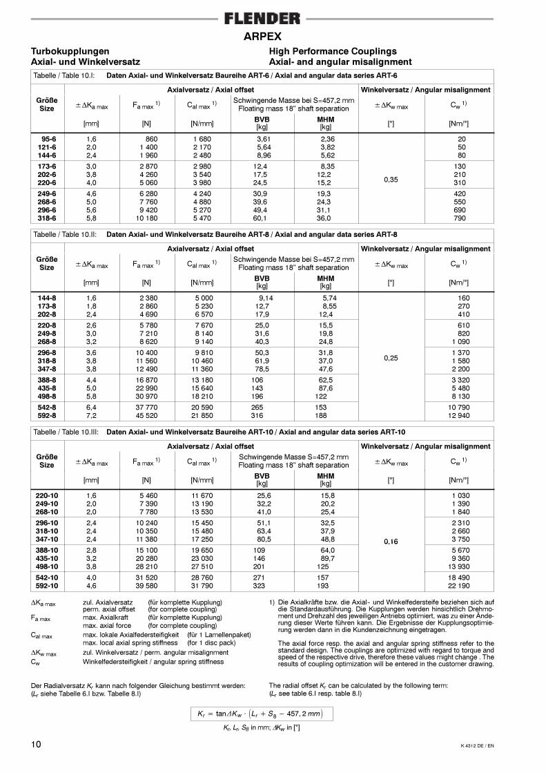
ARPEXTurbokupplungen High Performance CouplingsAxial- und Winkelversatz Axial- and angular misalignmentTabelle / Table 10.I: Daten Axial- und Winkelversatz Baureihe ART-6 / Axial and angular data series ART-6
Axialversatz / Axial offset Winkelversatz / Angular misalignmentGrˆfleSize !!Ka max Fa max
1) Cal max1) Schwingende Masse bei S=457,2 mm
Floating mass 18íí shaft separation !!Kw max Cw1)
[mm] [N] [N/mm] BVB[kg]
MHM[kg] [!] [Nm/!]
95-6121-6144-6
1,62,02,4
8601 4001 960
1 6802 1702 480
3,615,648,96
2,363,825,62
205080
173-6202-6220-6
3,03,84,0
2 8704 2605 060
2 9803 5403 980
12,417,524,5
8,3512,215,2 0,35
130210310
249-6268-6296-6318-6
4,65,05,65,8
6 2807 7609 420
10 180
4 2404 8805 2705 470
30,939,649,460,1
19,324,331,136,0
420550690790
Tabelle / Table 10.II: Daten Axial- und Winkelversatz Baureihe ART-8 / Axial and angular data series ART-8
Axialversatz / Axial offset Winkelversatz / Angular misalignmentGrˆfleSize !!Ka max Fa max
1) Cal max1) Schwingende Masse bei S=457,2 mm
Floating mass 18íí shaft separation !!Kw max Cw1)
[mm] [N] [N/mm] BVB[kg]
MHM[kg] [!] [Nm/!]
144-8173-8202-8
1,61,82,4
2 3802 8604 690
5 0005 2306 570
9,1412,717,9
5,748,55
12,4
160270410
220-8249-8268-8
2,63,03,2
5 7807 2108 620
7 6708 1409 140
25,031,640,3
15,519,824,8
610820
1 090
296-8318-8347-8
3,63,83,8
10 40011 56012 490
9 81010 46011 360
50,361,978,5
31,837,047,6
0,251 3701 5802 200
388-8435-8498-8
4,45,05,8
16 87022 99030 970
13 18015 64018 210
106143196
62,587,6
122
3 3205 4808 130
542-8592-8
6,47,2
37 77045 520
20 59021 850
265316
153188
10 79012 940
Tabelle / Table 10.III: Daten Axial- und Winkelversatz Baureihe ART-10 / Axial and angular data series ART-10
Axialversatz / Axial offset Winkelversatz / Angular misalignmentGrˆfleSize !!Ka max Fa max
1) Cal max1) Schwingende Masse S=457,2 mm
Floating mass 18íí shaft separation !!Kw max Cw1)
[mm] [N] [N/mm] BVB[kg]
MHM[kg] [!] [Nm/!]
220-10249-10268-10
1,62,02,0
5 4607 3907 780
11 67013 19013 530
25,632,241,0
15,820,225,4
1 0301 3901 840
296-10318-10347-10
2,42,42,4
10 24010 35011 380
15 45015 48017 250
51,163,480,5
32,537,948,8 0,16
2 3102 6603 750
388-10435-10498-10
2,83,23,8
15 10020 28028 210
19 65023 03027 510
109146201
64,089,7
125
0,165 6709 360
13 930
542-10592-10
4,04,6
31 52039 580
28 76031 790
271323
157193
18 49022 190
!Ka max zul. Axialversatz (f¸r komplette Kupplung)perm. axial offset (for complete coupling)
Fa max max. Axialkraft (f¸r komplette Kupplung)max. axial force (for complete coupling)
Cal max max. lokale Axialfedersteifigkeit (f¸r 1 Lamellenpaket)max. local axial spring stiffness (for 1 disc pack)
!Kw max zul. Winkelversatz / perm. angular misalignmentCw Winkelfedersteifigkeit / angular spring stiffness
Der Radialversatz Kr kann nach folgender Gleichung bestimmt werden:(Lr siehe Tabelle 6.I bzw. Tabelle 8.I)
1) Die Axialkr‰fte bzw. die Axial-- und Winkelfedersteife beziehen sich aufdie Standardausf¸hrung. Die Kupplungen werden hinsichtlich Drehmo-ment und Drehzahl des jeweiligen Antriebs optimiert, was zu einer ƒnde-rung dieser Werte f¸hren kann. Die Ergebnisse der Kupplungsoptimie-rung werden dann in die Kundenzeichnung eingetragen.
The axial force resp. the axial and angular spring stiffness refer to thestandard design. The couplings are optimized with regard to torque andspeed of the respective drive, therefore these values might change . Theresults of coupling optimization will be entered in the customer drawing.
The radial offset Kr can be calculated by the following term:(Lr see table 6.I resp. table 8.I)
Kr " tan!Kw # $Lr % S8 & 457, 2 mm'Kr, Lr, S8 in mm; "Kw in [!]

K 4312 DE / EN 11
ARPEXTurbokupplungen High Performance CouplingsTechnische Hinweise Technical information
Diagr. 11.I: Axiale RückstellkraftAxial restoring force
20 40 60 80 100
20
40
60
80
100
Axiale
Rückstellkraft
Axialrestoringforce
Axialversatz
ART--6
ART--8
ART--10
Axial offset[% "Kamax]
[%Famax]
RückstellkraftDie axiale Rückstellkraft kann mit Hilfe der Tabellen auf Seite 10 sowie Dia-
gramm 11.I bestimmt werden.
Axiale EigenfrequenzZur Bestimmung der axialen Eigenfrequenz läßt sich die Kupplung als Ein-
massenschwinger in Axialrichtung entsprechend Bild 11.I abbilden.
Im Normalfall stellt die axiale Eigenfrequenz für ARPEX-Turbokupplungen
aufgrund der nicht-linearen Kennlinie der Lamellen kein Problem dar, so-
lange nicht große Anregungen im Bereich der Eigenfrequenz der Kupplung
vorliegen.
Aus diesem Grunde sollte die axiale Eigenfrequenz, nach API 671, nicht im
Bereich (!10%) der Betriebsdrehzahl bzw. der zweifachen Betriebsdreh-
zahl liegen. Ansonsten muß Rücksprache mit Flender erfolgen.
Die axiale Eigenfrequenz fa kann, bei kleiner Amplitude, annähernd nach fol-
gender Formel bestimmt werden:
fa " 12"
#2 #Cal # Uf
mSch(
fa axiale Eigenfrequenz [Hz]
Cal lokale Federsteifigkeit (aus Diagramm 11.II) [N/mm]
mSch schwingende Masse [kg]
Uf Umrechnungsfaktor Uf = 1000 [mm/m]
Diagr. 11.III: Axiale Wellenverlagerung !Ka in Abhängigkeit desWinkelversatzes !Kw
Diagr. 11.III: Axial offset !Ka depending on angular misalignment!Kw
0,0
0,1
0,2
0,3
0,4
0 25 50 75 100 125 150
Axialversatz [%]Axial offset [%]
Win
kelv
erla
geru
ng [°
]A
ngul
ar m
isal
ignm
ent [
°]
ART-10
ART-8
ART-6
Dauerbetrieb
continuous operation
kurzzeitig zulässig
transient permissible
Diagr. 11.II: Lokale Axial--FedersteifigkeitLocal axial spring stiffness
20 40 60 80 100
20
40
60
80
100
ART--6
ART--8
ART--10
Lokale
Axial--Federsteifigkeit
Localaxialspringstiffness
AxialversatzAxial offset
[% "Kamax][%
Calmax]
Restoring forceThe axial restoring force can be determined with the help of the tables on
page 10 as well as diagram 11.I.
Axial natural frequencyFordeterminationof theaxial natural frequency, the coupling can be reflected
as a one--mass--vibrator in axial direction, acc. to figure 11.I.
Normally the axial natural frequency is not a concern for ARPEX-High Per-
formance couplings due to the non-linear characteristic of the discs, as long
no large excitation in the range of the coupling axial natural frequency exists.
Therefore the axial natural frequency, by API 671, should not fall within
!10% of the nominal speed resp. two times the nominal speed. Otherwise
contact Flender.
The axial natural frequency fa can approximately be calculated, in case of a
small amlpitude, by the following term:
fa " 12"
#2 #Cal # Uf
mSch(
fa axial natural frequency [Hz]
Cal local spring stiffness (from diagram 11.II) [N/mm]
mSch floating mass [kg]
Uf conversion factor Uf = 1000 [mm/m]
Bild 11.I: Feder--Masse--System einer Arpex KupplungFig. 11.I: Spring--mass--system of Arpex coupling
schwingende Masse
floating mass
mSch
Cal Cal
!Ka2 !
Ka2
K 4312 DE / EN12
ARPEXTurbokupplungen High Performance CouplingsAuslegung und Berechnungsbeispiel Selection and calculation example
Auslegung
Folgende Daten sollten f¸r eine korrekte Auslegung bekannt sein:" Nennleistung [kW]" Nenndrehzahl [min--1]" Peakmoment [Nm]" max. Drehzahl (‹berdrehzahl) [min--1]" DBSE: Wellenabstand" Axialversatz" Winkel-- oder Radialversatz" Bohrungsdurchmesser treibende Nabe" Bohrungsdurchmesser getriebene Nabe
Auslegung f¸r Dauerbetrieb
TNenn ! 9550 " Pn
TKN # TNenn " f1
Betriebsfaktor f1Die nachfolgenden Faktoren gelten f¸r ruhig laufende Antriebsmaschi-nen wie Turbinen oder E--Motoren.F¸r jede Berechnungmufl ein Betriebsfaktor vonmin. 1,5 ber¸cksichtigtwerden.DerBetriebsfaktor ist auf dasmaximaleNennmomentder Anwendungzubeziehen.
Konstantes Moment 1.5Beispiel: Turbinen, Zentrifugalkompressoren, Getriebe, Kessel-speisepumpen usw.
API 671 1.75
M‰flige Drehmomentschwankungen 2Beispiel: grofle Gebl‰se, Schraubenkompressoren
Anwendungen, bei denen hohe Drehmomentschwankungen auftreten,werden gesondert ausgelegt. In diesen F‰llen werden spezifische Be-triebsfaktoren erforderlich. Bitte R¸cksprache mit Flender halten.
Folgendes pr¸fen
NachAuslegung vonKupplungsausf¸hrung und -grˆfle bleiben folgendeParameter zu pr¸fen:" max. Bohrungsdurchmesser der Kupplungsnaben" zul. Vers‰tze der Kupplung" Peakmoment" max. Drehzahl
Berechnungsbeispiel
Dampfturbine -- Getriebe -- Generator:Max. Nennbetrieb: 19500 kW bei 7500 min--1Peakmoment: 6 ∑ TNennWellenabstand 457,2 mm (18î)API 671 Anwendung: f1 = 1,75Turbinenwelle: 150 mm, ˆlhydraulischer KegelpreflverbandGetriebewelle: 150 mm, ˆlhydraulischer KegelpreflverbandAxialversatz ! 3 mm
TNenn ! 9550 " 195007500
! 24830 Nm
TPeak ! 6 " 24830 Nm ! 148980 Nm
Auswahl:
ART-8 BVB 388-8TKN = 117000 NmTPeak= 152100 Nmnmax = 9800 min--1max. Axialversatz !Ka = ! 4,4 mmmax. Winkelversatz !Kw = 0,25"max. Bohrungsdurchmesser der Nabe D1 = 160 mm
Wie in diesemBeispiel wird die Kupplungsgrˆfle oft durch im Antrieb auf-tretende Peakmomente festgelegt.F¸r eine optimale Auslegung der Kupplung sind Angaben zur Art undHˆhe der auftretenden Belastungen mit den entsprechenden Lastwech-selzahlen erforderlich.
Selection
The following data should be known for a proper selection:" Continuous power [kW]" Continuous speed [rpm]" Peak torque [Nm]" Maximum speed (tripspeed) [rpm]" DBSE: Distance between shaft ends" Axial displacement" Angular misalignment or parallel offset" Bore diameter driver hub" Bore diameter driven hub
Selection for continuous operation
TNenn ! 9550 " Pn
TKN # TNenn " f1
Application factor f1The factors given below apply to smooth power driving machines as tur-bines and motors.For every calculation a minimum application factor of 1.5 must be con-sidered.The application factor has to be refered to the maximum continuoustorque of the application.
Constant torque 1.5Example: Turbines, Centrifugal compressors, Gearboxes,Boiler feed pumps etc.
API 671 1.75
Moderate torque fluctuations 2Examples: large Fans, Screw Compressors etc.
Applications, where significant torque fluctuations occur, should be sep-arately analysed. In these cases specific applications factors are re-quired. Please consult Flender.
Check the following
After selection of coupling type and size check these parameters:
" maximum bore diameter of the coupling hubs" misalignment capacity of the coupling" peak torque capacity" maximum speed capacity
Calculation example
Steam Turbine -- Gear Box -- Generator:Max. continuous duty: 19500 kW at 7500 rpmPeak torque: 6 ∑ TNennShaft separation 457,2 mm (18î)API 671 application: f1 = 1,75Turbine shaft: 150 mm tapered hydraulic fitGear shaft: 150 mm tapered hydraulic fitAxial displacement ! 3 mm
TNenn ! 9550 " 195007500
! 24830 Nm
TPeak ! 6 " 24830 Nm ! 148980 Nm
Selection:
ART-8 BVB 388-8TKN = 117000 NmTPeak= 152100 Nmnmax = 9800 rpmmax. axial displacement !Ka = ! 4,4 mmmax. angular misalignment !Kw = 0,25"max. bore capacity of the hub D1 = 160 mm
As in this example the coupling size is often determined by the peaktorque of the application.To get an optimized selection of the coupling it is necessary to knowwhatkind and quantity of loads occur and which number of load alternationspredominate during operation.
Um dem hohen Qualit‰tsanspruch gegen-¸ber ARPEX-Kupplungen gerecht zu wer-den, ist die Entwicklung und Herstellung vonARPEX-Kupplungen in ein zertifiziertes Qua-lit‰tsmanagement-System nach den Vorga-ben der DIN EN ISO 9001 eingebunden.
The design and manufacture of ARPEX-Couplings is integrated into a certified Qual-ity Management System according to DINEN ISO 9001 to fulfil the high quality de-mands on ARPEX-Couplings.
!"#$%K 4312 DE / EN 13
ARPEXTurbokupplungen High Performance CouplingsTechnische Informationen Technical information
WuchtenGrunds‰tzlich ist es mˆglich die Kupplung nach jeder der in der API 671 be-schriebenen Methoden oder nach ‰hnlichen Vorschriften zu wuchten.Folgende Mˆglichkeiten sind nach API 671 gegeben:D Einzelteilwuchtung mit der Mˆglichkeit, gleiche Bauteile auszutauschenD Summenwuchtung als Pr¸fung der Einzelteilwuchtung, Korrekturen wer-den nur durch Wiederholen der Einzelteilwuchtung durchgef¸hrt; die Einzel-teile kˆnnen beliebig montiert werdenD Summenwuchtungmit Wuchtkorrektur der komplettenKupplung, einAus-tausch der Einzelteile ohne neue Wuchtung ist nicht mehr mˆglich.Wuchten nach DIN ISO 1940, Teil 1 ist ebenfalls mˆglich.
Transport- und MontagehilfeF¸r das Wuchten, den Transport und die Montage sind Transportschraubenvorgesehen, mit deren Hilfe die Lamellenpakete starr gesetzt werden. Da-durch werden die Lamellen vor Besch‰digung w‰hrend des Transports oderder Montage gesch¸tzt.Vor der InbetriebnahmederKupplungm¸ssendie Transportschraubenunbe-dingt entfernt werden.
Axiales VorspannenWenn ƒnderungen des Wellenabstands z. B. durch W‰rmedehnung im vor-aus bekannt sind, kˆnnen die Lamellenpakete axial vorgespannt werden, sodafl w‰hrend des Betriebs die Kupplung in neutraler Position operiert.
AusgleichspaketeBei kegeligen Nabenbohrungen werden die Kupplungen mit Ausgleichspa-keten ausgeliefert. Dadurch ist eine Korrektur desWellenabstands von$ ei-ner Paketdicke mˆglich (siehe API 671).
Welle / Nabe -- VerbindungARPEX-Turbokupplungen werden normalerweise mit kegeligen Bohrungenf¸r ˆlhydraulischeMontage bzw. Demontage ausgef¸hrt. Flanschausf¸hrun-gen sind ebenfalls lieferbar.F¸r die genaue Ausf¸hrung der Nabenbohrungen bzw. der Flansche sind n‰-here Angaben erforderlich.
SicherheitsvorkehrungenUmlaufende Teilem¸ssen vomK‰ufer gegenunbeabsichtigtes Ber¸hrenge-sichert werden.
Ein- und Ausbau der KupplungenARPEX-Turbokupplungen der verschiedenen Bauarten ermˆglichen denEin- und Ausbau der Kupplung und Maschinen ohne deren axiale Verschie-bung.
Einbau und InbetriebnahmeF¸rdenEinbauunddie InbetriebnahmevonARPEX-Turbokupplungen ist diejeweilige Montageanleitung zu beachten, die jeder ausgelieferten Kupplungbeiliegt.
AnlieferungszustandDie ARPEX-Turbokupplungenwerden als komplette Kupplungseinheitenmitvormontierten Lamellenpaketen ausgeliefert.Bei der Ausf¸hrung BVB sind die B-Module vormontiert.Bei der Ausf¸hrung MHM ist die Baugruppe ìHî vormontiert.Eine Demontage dieser Kupplungsteile darf nur nachR¸cksprache mit Flen-der erfolgen.
Technische ƒnderungenMafl‰nderungen bei Weiterentwicklung sowie ƒnderungen technischer An-gaben sind mˆglich.
BalancingOn principle it is possible to balance the coupling to all of the API 671 optionsor similar instructions.The following possibilities are given in the API 671:D Component balance with the possibility to interchange duplicate compo-nentsD Assembly balance as check of the component balance, balance correc-tion only by repeating the component balance, the components can be as-sembled in any positionD Assembly balance with balance correction on the complete coupling, theinterchange of components without new balance not possible.Balancing acc. DIN ISO 1940, part 1 is also possible.
Shipping and installation deviceFor balancing, shipping and installation the disc packs are locked and stabil-ized by means of shipping screws. That way the discs are protected againstdamage during shipping and installation.The shipping screws must be replaced prior to operation.
Axial prestretchingIf changes in the shaft distancee. g. by thermal growth are known inadvance,thedisc packs canbeprestretched inaxial direction, so that the coupling runsin a neutral position during operation.
Shim-packsWhen tapered hub bores are specified the coupling is supplied with shim-packs. This allows an adjustment of the spacer gap of$ the thickness of oneshim-pack (see API 671).
Shaft / hub connectionARPEX-High PerformanceCouplings are normally providedwith taper boresfor oilhydraulic assembly resp. disassembly. Flange design is available too.For the exact design of the hub bores resp. the flanges detailed data arenecessary.
Safety precautionsThe user must guard moving machine elements so as not to endanger anyperson.
Fitting and removing couplingsARPEX-HighPerformanceCouplings enable fitting and removing of couplingand machines without displacing them axially.
Installation and putting into operationFor installation and putting into operation, observe the respective operatinginstructions which are supplied with each coupling.
Condition of deliveryThe ARPEX-High Performance Couplings are supplied as complete unitswith preassembled disc packs.At the design BVB the B-units are preassembled.At the design MHM the transmission unit ìHî is preassembled.Disassembly of these coupling parts are only allowed to be carried out afterconsultation with Flender.
Technical changesChange of dimensions and technical values due to further technical develop-ment.
K4312 DE/EN14
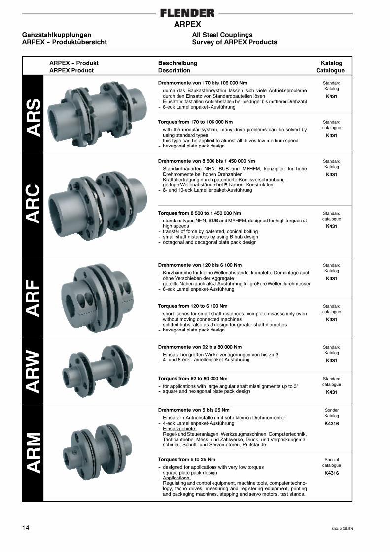
ARPEXGanzstahlkupplungen All Steel CouplingsARPEX -- Produkt¸bersicht Survey of ARPEX Products
Drehmomente von 92 bis 80 000 Nm
-- Einsatz bei groflen Winkelverlagerungen von bis zu 3!-- 4- und 6-eck Lamellenpaket-Ausf¸hrung
ARPEX -- Produkt Beschreibung Katalog
SonderKatalog
K4316
Drehmomente von 170 bis 106 000 Nm
-- durch das Baukastensystem lassen sich viele Antriebsproblemedurch den Einsatz von Standardbauteilen lˆsen
-- Einsatz in fast allen Antriebsf‰llenbei niedriger bis mittlererDrehzahl-- 6-eck Lamellenpaket--Ausf¸hrung
StandardKatalog
K431
StandardKatalog
K431
Drehmomente von 5 bis 25 Nm
-- Einsatz in Antriebsf‰llen mit sehr kleinen Drehmomenten-- 4-eck Lamellenpaket-Ausf¸hrung-- Einsatzgebiete:Regel- und Steueranlagen, Werkzeugmaschinen, Computertechnik,Tachoantriebe, Mess- und Z‰hlwerke, Druck- und Verpackungsma-schinen, Schritt- und Servomotoren, Pr¸fst‰nde
Torques from 92 to 80 000 Nm
-- for applications with large angular shaft misalignments up to 3!-- square and hexagonal plate pack design
Torques from 170 to 106 000 Nm
-- with the modular system, many drive problems can be solved byusing standard types
-- this type can be applied to almost all drives low medium speed-- hexagonal plate pack design
Standardcatalogue
K431
Torques from 5 to 25 Nm
-- designed for applications with very low torques-- square plate pack design-- Applications:Regulating and control equipment, machine tools, computer techno-logy, tacho drives, measuring and registering equipment, printingand packaging machines, stepping and servo motors, test stands.
Standardcatalogue
K431
Specialcatalogue
K4316
ARPEX Product Description Catalogue
ARS
ARW
ARM
ARC
ARF
Drehmomente von 8 500 bis 1 450 000 Nm
-- Standardbauarten NHN, BUB and MFHFM, konzipiert f¸r hoheDrehmomente bei hohen Drehzahlen
-- Kraft¸bertragung durch patentierte Konusverschraubung-- geringe Wellenabst‰nde bei B-Naben--Konstruktion-- 8- und 10-eck Lamellenpaket-Ausf¸hrung
StandardKatalog
K431
Standardcatalogue
K431
Drehmomente von 120 bis 6 100 Nm
-- Kurzbaureihe f¸r kleine Wellenabst‰nde; komplette Demontage auchohne Verschieben der Aggregate
-- geteilte Naben auch als J-Ausf¸hrung f¸r grˆflereWellendurchmesser-- 6-eck Lamellenpaket-Ausf¸hrung
StandardKatalog
K431
Torques from 120 to 6 100 Nm
-- short--series for small shaft distances; complete disassembly evenwithout moving connected machines
-- splitted hubs, also as J design for greater shaft diameters-- hexagonal plate pack design
Standardcatalogue
K431
Torques from 8 500 to 1 450 000 Nm
-- standard types NHN, BUB andMFHFM, designed for high torques athigh speeds
-- transfer of force by patented, conical bolting-- small shaft distances by using B hub design-- octagonal and decagonal plate pack design
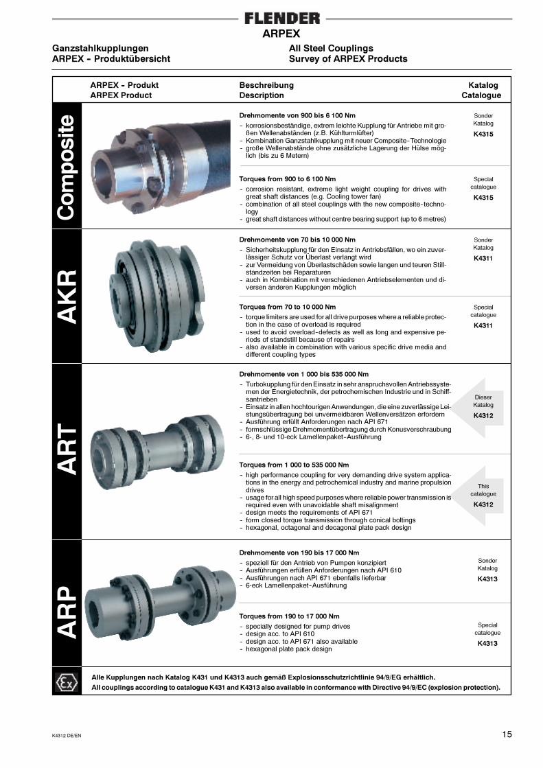
K4312 DE/EN 15
ARPEXGanzstahlkupplungen All Steel CouplingsARPEX -- Produkt¸bersicht Survey of ARPEX Products
Torques from 190 to 17 000 Nm-- specially designed for pump drives-- design acc. to API 610-- design acc. to API 671 also available-- hexagonal plate pack design
Torques from 70 to 10 000 Nm-- torque limiters are used for all drivepurposes wherea reliable protec-tion in the case of overload is required
-- used to avoid overload--defects as well as long and expensive pe-riods of standstill because of repairs
-- also available in combination with various specific drive media anddifferent coupling types
Specialcatalogue
K4311
SonderKatalog
K4311
Drehmomente von 190 bis 17 000 Nm-- speziell f¸r den Antrieb von Pumpen konzipiert-- Ausf¸hrungen erf¸llen Anforderungen nach API 610-- Ausf¸hrungen nach API 671 ebenfalls lieferbar-- 6-eck Lamellenpaket--Ausf¸hrung
Drehmomente von 70 bis 10 000 Nm-- Sicherheitskupplung f¸r den Einsatz in Antriebsf‰llen, wo ein zuver-l‰ssiger Schutz vor ‹berlast verlangt wird
-- zur Vermeidung von ‹berlastsch‰den sowie langen und teuren Still-standzeiten bei Reparaturen
-- auch in Kombination mit verschiedenen Antriebselementen und di-versen anderen Kupplungen mˆglich
ARPEX -- Produkt Beschreibung KatalogARPEX Product Description Catalogue
ARP
ART
AKR
SonderKatalog
K4315
Drehmomente von 900 bis 6 100 Nm-- korrosionsbest‰ndige, extrem leichte Kupplung f¸r Antriebe mit gro-flen Wellenabst‰nden (z.B. K¸hlturml¸fter)
-- Kombination Ganzstahlkupplung mit neuer Composite--Technologie-- grofle Wellenabst‰nde ohne zus‰tzliche Lagerung der H¸lse mˆg-lich (bis zu 6 Metern)
Specialcatalogue
K4315
Torques from 900 to 6 100 Nm-- corrosion resistant, extreme light weight coupling for drives withgreat shaft distances (e.g. Cooling tower fan)
-- combination of all steel couplings with the new composite--techno-logy
-- great shaft distances without centre bearing support (up to 6metres)Com
posite
SonderKatalog
K4313
Specialcatalogue
K4313
Alle Kupplungen nach Katalog K431 und K4313 auch gem‰fl Explosionsschutzrichtlinie 94/9/EG erh‰ltlich.All couplings according to catalogueK431 andK4313 also available in conformancewith Directive 94/9/EC (explosion protection).
DieserKatalog
K4312
Torques from 1 000 to 535 000 Nm-- high performance coupling for very demanding drive system applica-tions in the energy and petrochemical industry and marine propulsiondrives
-- usage for all high speed purposeswhere reliable power transmission isrequired even with unavoidable shaft misalignment
-- design meets the requirements of API 671-- form closed torque transmission through conical boltings-- hexagonal, octagonal and decagonal plate pack design
Thiscatalogue
K4312
Drehmomente von 1 000 bis 535 000 Nm-- Turbokupplung f¸r denEinsatz in sehr anspruchsvollenAntriebssyste-men der Energietechnik, der petrochemischen Industrie und in Schiff-santrieben
-- Einsatz in allenhochtourigenAnwendungen, die eine zuverl‰ssigeLei-stungs¸bertragung bei unvermeidbaren Wellenvers‰tzen erfordern
-- Ausf¸hrung erf¸llt Anforderungen nach API 671-- formschl¸ssige Drehmoment¸bertragung durch Konusverschraubung-- 6-, 8- und 10-eck Lamellenpaket--Ausf¸hrung
K4312 DE / EN16
ARPEXTurbokupplungen High Performance CouplingsBemerkungen Notes
.................................................................................................................
.................................................................................................................
.................................................................................................................
.................................................................................................................
.................................................................................................................
.................................................................................................................
.................................................................................................................
.................................................................................................................
.................................................................................................................
.................................................................................................................
.................................................................................................................
.................................................................................................................
.................................................................................................................
.................................................................................................................
.................................................................................................................
.................................................................................................................
.................................................................................................................
.................................................................................................................
.................................................................................................................
.................................................................................................................
.................................................................................................................
.................................................................................................................
.................................................................................................................
.................................................................................................................
.................................................................................................................
.................................................................................................................
.................................................................................................................
.................................................................................................................
.................................................................................................................
.................................................................................................................
.................................................................................................................
.................................................................................................................
.................................................................................................................
.................................................................................................................
FLENDER Germany (2004-08)
A. FRIEDR. FLENDER AG - 46393 BocholtLieferanschrift: Alfred-Flender-Strasse 77, 46395 BocholtTel.: (0 28 71) 92 - 0; Fax: (0 28 71) 92 - 25 96E-mail: [email protected] � www.flender.com–––––––––––––––––––––––––––––––––––––––––––––––––––––––––––––––––––––––––––––––––––VERTRIEBSZENTRUM BOCHOLT 46393 Bocholt
Alfred-Flender-Strasse 77, 46395 BocholtTel.: (0 28 71) 92 - 0; Fax: (0 28 71) 92 - 14 35E-mail: [email protected]
_______________________________________________________________________________________________________________________________________________
VERTRIEBSZENTRUM STUTTGART 70472 StuttgartFriolzheimer Strasse 3, 70499 StuttgartTel.: (07 11) 7 80 54 - 51; Fax: (07 11) 7 80 54 - 50E-mail: [email protected]
_______________________________________________________________________________________________________________________________________________
VERTRIEBSZENTRUM MÜNCHEN 85750 KarlsfeldLiebigstrasse 14, 85757 KarlsfeldTel.: (0 81 31) 90 03 - 0; Fax: (0 81 31) 90 03 - 33E-mail: [email protected]
_______________________________________________________________________________________________________________________________________________
VERTRIEBSZENTRUM BERLIN Schlossallee 8, 13156 BerlinTel.: (0 30) 91 42 50 58; Fax: (0 30) 47 48 79 30E-mail: [email protected]
–––––––––––––––––––––––––––––––––––––––––––––––––––––––––––––––––––––––––––––––––––A. FRIEDR. FLENDER AG Am Industriepark 2, 46562 VoerdeWerk Friedrichsfeld Tel.: (0 28 71) 92 - 0; Fax: (0 28 71) 92 - 25 96
E-mail: [email protected] � www.flender.com
A. FRIEDR. FLENDER AG Thierbacher Strasse 24, 09322 PenigGetriebewerk Penig Tel.: (03 73 81) 60; Fax: (03 73 81) 8 02 86
E-mail: [email protected] � www.flender.com
A. FRIEDR. FLENDER AG Industriepark Bocholt, Schlavenhorst 100, 46395 BocholtKupplungswerk Mussum Tel.: (0 28 71) 92 - 28 68; Fax: (0 28 71) 92 - 25 79
E-mail: [email protected] � www.flender.com
A. FRIEDR. FLENDER AG Obere Hauptstrasse 228 - 230, 09228 Chemnitz / WittgensdorfFLENDER GUSS Tel.: (0 37 22) 64 - 0; Fax: (0 37 22) 94 - 1 38
E-mail: [email protected] � www.flender-guss.de
FLENDER SERVICE GMBH 44607 HerneSüdstrasse 111, 44625 HerneTel.: (0 23 23) 9 40 - 0; Fax: (0 23 23) 9 40 - 3 33E-mail: [email protected] � www.flender-service.com24h Service Hotline +49 (0) 17 22 81 01 00
WINERGY AG Am Industriepark 2, 46562 VoerdeTel.: (0 28 71) 924; Fax: (0 28 71) 92 - 24 87E-mail: [email protected] � www.winergy-ag.com
FLENDER TÜBINGEN GMBH 72007 TübingenBahnhofstrasse 40, 72072 TübingenTel.: (0 70 71) 7 07 - 0; Fax: (0 70 71) 7 07 - 4 00E-mail: [email protected] � www.flender.com
LOHER GMBH 94095 RuhstorfHans-Loher-Strasse 32, 94099 RuhstorfTel.: (0 85 31) 3 90; Fax: (0 85 31) 3 94 37E-mail: [email protected] � www.loher.de
–––––––––––––––––––––––––––––––––––––––––––––––––––––––––––––––––––––––––––––––––––FRANKREICHFlender-Graffenstaden SA1, rue du Vieux Moulin 67400 Illkirch-Graffenstaden B.P. 84; 67402 Illkirch-GraffenstadenPhone: +33 (3) 88 67 60 00; Fax: +33 (3) 88 67 06 17 E-mail: [email protected]
FLENDER International (2004-08)
E U R O P EAUSTRIAFlender Ges.m.b.H.Industriezentrum Nö-SüdStrasse 4, Objekt 14Postfach 1322355 Wiener NeudorfPhone: +43 (0) 22 36 - 6 45 70Fax: +43 (0) 22 36 - 6 45 70 10E-mail: [email protected]
BELGIUM & LUXEMBOURGN.V. Flender Belge S.A.Cyriel Buyssestraat 1301800 VilvoordePhone: +32 (0) 2 - 2 53 10 30Fax: +32 (0) 2 - 2 53 09 66E-mail: [email protected]
BULGARIAA. Friedr. Flender AGBranch Officec/o Auto - Profi GmbHAlabin Str. 52, 1000 SofiaPhone: +359 (0) 2 - 9 80 66 06Fax: +359 (0) 2 - 9 80 33 01E-mail: [email protected]
CROATIA / SLOVENIABOSNIA-HERZEGOVINAA. Friedr. Flender AGBranch Officec/o HUM - Naklada d.o.o.Mandroviceva 310000 ZagrebPhone: +385 (0) 1 - 2 30 60 25Fax: +385 (0) 1 - 2 30 60 24E-mail: [email protected]
CZECH REPUBLICA. Friedr. Flender AGBranch OfficeHotel DUO, Teplicka 1719000 Praha 9Phone: +420 2 - 83 88 23 00Fax: +420 2 - 83 88 22 05E-mail:[email protected]
DENMARKFlender Scandinavia A/SRugmarken 35 B3520 FarumPhone: +45 - 70 22 60 03Fax: +45 - 44 99 16 62E-mail: [email protected]
ESTHONIA / LATVIALITHUANIAFlender Branch OfficeAddinol MineralölMarketing OÜSuur-Söjamäe 3211415 Tallinn / EsthoniaPhone: +372 (0) 6 - 27 99 99Fax: +372 (0) 6 - 27 99 90E-mail: [email protected]
FINLANDFlender OyRuosilantie 2 B00390 HelsinkiPhone: +358 (0) 9 - 4 77 84 10Fax: +358 (0) 9 - 4 36 14 10E-mail: [email protected]
FRANCEFlender S.a.r.l.3, rue Jean Monnet - B.P. 578996 Elancourt Cedex
Phone: +33 (0) 1 - 30 66 39 00Fax: +33 (0) 1 - 30 66 35 13E-mail: [email protected]
SALES OFFICE:Flender S.a.r.lAgence de LyonParc Inopolis, Route de Vourles69230 Saint Genis LavalPhone: +33 (0) 4 - 72 83 95 20Fax: +33 (0) 4 - 72 83 95 39E-mail: [email protected]
Flender-Graffenstaden SA1, rue du Vieux Moulin67400 Illkirch-GraffenstadenB.P. 8467402 Illkirch-GraffenstadenPhone: +33 (0) 3 - 88 67 60 00Fax: +33 (0) 3 - 88 67 06 17E-mail:[email protected]
GREECEFlender Hellas Ltd.2, Delfon str., 11146 AthensPhone: +30 210 - 2 91 72 80Fax: +30 210 - 2 91 71 02E-mail: [email protected]
HUNGARYA. Friedr. Flender AGBranch OfficeBécsi Út 3 - 5, 1023 BudapestPhone: +36 (0) 1 - 3 45 07 90Fax: +36 (0) 1 - 3 45 07 92E-mail:[email protected]
ITALYFlender Cigala S.p.A.Parco Tecnologico ManzoniPalazzina GViale delle industrie, 1720040 Caponago (MI)Phone: +39 (0) 02 - 95 96 31Fax: +39 (0) 02 - 95 74 39 30E-mail: [email protected]
THE NETHERLANDSFlender Nederland B.V.Lage Brink 5 - 77317 BD ApeldoornPostbus 10737301 BH ApeldoornPhone: +31 (0) 55 - 5 27 50 00Fax: +31 (0) 55 - 5 21 80 11E-mail: [email protected]
Bruinhof B.V.Boterdiep 373077 AW RotterdamPostbus 96073007 AP RotterdamPhone: +31 (0) 10 - 4 97 08 08Fax: +31 (0) 10 - 4 82 43 50E-mail: [email protected]
NORWAYPlease refer toFlender Scandinavia A/SRugmarken 35 B3520 FarumPhone: +45 - 70 22 60 03Fax: +45 - 44 99 16 62E-mail: [email protected]
POLANDA. Friedr. Flender AGBranch OfficePrzedstawicielstwo w Polsceul. Wyzwolenia 2743 - 190 Mikolów
Phone: +48 (0) 32 - 2 26 45 61Fax: +48 (0) 32 - 2 26 45 62E-mail: [email protected]
PORTUGALRodamientos FEYC, S.A.R. Jaime Lopes Dias, 1668 CV1750 - 124 LissabonPhone: +351 (0) 21 7 54 24 10Fax: +351 (0) 21 7 54 24 19E-mail: [email protected]
ROMANIAA. Friedr. Flender AGBranch OfficeB-dul Garii Obor Nr. 8DSector 2 - BucurestiPhone: +40 (0) 21 - 2 53 21 28Fax: +40 (0) 21 - 2 52 98 60E-mail: [email protected]
RUSSIAF & F GmbHTjuschina 4 - 6191119 St. PetersburgPhone: +7 (0) 812 - 3 20 90 34Fax: +7 (0) 812 - 3 40 27 60E-mail:[email protected]
SLOVAKIAA. Friedr. Flender AGBranch OfficeVajanského 49P.O. Box 286, 08001 PresovPhone: +421 (0) 51 - 7 70 32 67Fax: +421 (0) 51 - 7 70 32 67E-mail:[email protected]
SPAINFlender Ibérica S.A.Poligono Industrial San MarcosCalle Morse, 31 (Parcela D-15)28906 Getafe, MadridPhone: +34 (0) 91 - 6 83 61 86Fax: +34 (0) 91 - 6 83 46 50E-mail: [email protected]
SWEDENFlender ScandinaviaÄsenvägen 244339 LerumPhone: +46 (0) 302 - 1 25 90Fax: +46 (0) 302 - 1 25 56E-mail: [email protected]
SWITZERLANDFlender AGZeughausstr. 485600 LenzburgPhone: +41 (0) 62 - 8 85 76 00Fax: +41 (0) 62 - 8 85 76 76E-mail: [email protected]
TURKEYFlender GücAktarma SistemleriSanayi ve Ticaret Ltd. Sti.IMES Sanayi, SitesiE Blok 502, Sokak No. 2281260 Dudullu - IstanbulPhone: +90 (0) 216 - 4 66 51 41Fax: +90 (0) 216 - 3 64 59 13E-mail: [email protected]
UKRAINEA. Friedr. Flender AGBranch Officec/o DIV - Deutsche Industriever.Prospect Pobedy 44252057 KievPhone: +380 (0) 44 - 4 46 80 49Fax: +380 (0) 44 - 2 30 29 30E-mail: [email protected]
UNITED KINGDOM & EIREFlender Power Transmission Ltd.Thornbury Works, Leeds RoadBradfordWest Yorkshire BD3 7EBPhone: +44 (0) 12 74 - 65 77 00Fax: +44 (0) 12 74 - 66 98 36E-mail:[email protected]
SERBIA-MONTENEGROALBANIA / MACEDONIAA. Friedr. Flender AGBranch Officec/o G.P.Inzenjering d.o.o.III Bulevar 54 / 1911070 Novi BeogradPhone: +381 (0) 11 - 60 44 73Fax: +381 (0) 11 - 3 11 67 91E-mail: [email protected]
A F R I C ANORTH AFRICANCOUNTRIESPlease refer to Flender s.a.r.l3, rue Jean Monnet - B.P. 578996 Elancourt CedexPhone: +33 (0) 1 - 30 66 39 00Fax: +33 (0) 1 - 30 66 35 13E-mail: [email protected]
EGYPTSons of Farid Hassanen81 Matbaa Ahlia StreetBoulac 11221, CairoPhone: +20 (0) 2 - 5 75 15 44Fax: +20 (0) 2 - 5 75 17 02E-mail: [email protected]
SOUTH AFRICAFlender Power Transmission (Pty.) Ltd.Cnr. Furnace St & Quality Rd.P.O. Box 131, Isando 1600JohannesburgPhone: +27 (0) 11 - 5 71 20 00Fax: +27 (0) 11 - 3 92 24 34E-mail: [email protected]
SALES OFFICES:Flender Power Transmission (Pty.) Ltd.Unit 3 Marconi Park9 Marconi Crescent, MontagueGardens, P.O. Box 37291Chempet 7442, Cape TownPhone: +27 (0) 21 - 5 51 50 03Fax: +27 (0) 21 - 5 52 38 24E-mail: [email protected]
Flender Power Transmission (Pty.) Ltd.Unit 3 Goshawk ParkFalcon Industrial EstateP.O. Box 1608New Germany 3620, DurbanPhone: +27 (0) 31 - 7 05 38 92Fax: +27 (0) 31 - 7 05 38 72E-mail: [email protected]
Flender Power Transmission (Pty.) Ltd.9 Industrial Crescent, Ext. 25P.O. Box 17609, Witbank 1035Phone: +27 (0) 13 - 6 92 34 38Fax: +27 (0) 13 - 6 92 34 52E-mail: [email protected]
Flender Power Transmission (Pty.) Ltd.Unit 14 King Fisher Park, AltonCnr. Ceramic Curve & AluminaAllee, P.O. Box 101995Meerensee 3901Richards BayPhone: +27 (0) 35 - 7 51 15 63Fax: +27 (0) 35 - 7 51 15 64E-mail: [email protected]
A M E R I C AARGENTINAChilicote S.A.Avda. Julio A. Roca 546C 1067 ABN Buenos AiresPhone: +54 (0) 11 - 43 31 66 10Fax: +54 (0) 11 - 43 31 42 78E-mail:[email protected]
BRASILFlender Brasil Ltda.Rua Quatorze, 60Cidade Industrial32211 - 970, Contagem - MGPhone: +55 (0) 31 - 33 69 21 00Fax: +55 (0) 31 - 33 69 21 66E-mail:[email protected]
SALES OFFICES:Flender Brasil Ltda.Rua James Watt, 142conj. 142 - Brooklin Novo04576 - 050, São Paulo - SPPhone: +55 (0) 11 - 55 05 99 33Fax: +55 (0) 11 - 55 05 30 10E-mail: [email protected]
Flender Brasil Ltda.Rua Campos Salles, 1095sala 04 - Centro14015-110, Ribeirão Preto - SPPhone: +55 (0) 16 - 6 35 15 90Fax: +55 (0) 16 - 6 35 11 05E-mail:[email protected]
CANADAFlender Power Transmission Inc.215 Shields Court, Units 4 - 6Markham, Ontario L3R 8V2Phone: +1 (0) 9 05 - 3 05 10 21Fax: +1 (0) 9 05 - 3 05 10 23E-mail: [email protected]
CHILE / ARGENTINABOLIVIA / ECUADORPARAGUAY / URUGUAYFlender Cono Sur LimitadaAvda. Galvarino Gallardo 1534Providencia, SantiagoPhone: +56 (0) 2 - 2 35 32 49Fax: +56 (0) 2 - 2 64 20 25E-mail: [email protected]
COLOMBIAA.G.P. Representaciones Ltda.Flender Liaison Office ColombiaAv Boyaca No 23A50 Bodega UA 7-1, BogotáPhone: +57 (0) 1 - 5 70 63 53Fax: +57 (0) 1 - 5 70 73 35E-mail: [email protected]
MEXICOFlender de Mexico S.A. de C.V.17, Pte, 713 Centro72000 PueblaPhone: +52 (0) 222 - 2 37 19 00Fax: +52 (0) 222 - 2 37 11 33E-mail:[email protected]
SALES OFFICES:Flender de Mexico S.A. de C.V.Lago Nargis No. 38Col. Granada11520 Mexico, D.F.Phone: +52 (0) 55 - 52 54 30 37Fax: +52 (0) 55 - 55 31 69 39E-mail:[email protected]
Flender de Mexico S.A. de C.V.Ave. San Pedro No. 231-5Col. Miravalle64660 Monterrey, N.L.Phone: +52 (0) 81 - 83 63 82 82Fax: +52 (0) 81 - 83 63 82 83E-mail:[email protected]
PERUPotencia Industrial E.I.R.L.Calle Gonzales Olaechea110-URB, La AuroraMiraflores, LimaPhone: +51 (0) 1 - 2 42 84 68Fax: +51 (0) 1 - 2 42 08 62E-mail: [email protected]
USAFlender Corporation950 Tollgate RoadP.O. Box 1449Elgin, IL. 60123Phone: +1 (0) 8 47 - 9 31 19 90Fax: +1 (0) 8 47 - 9 31 07 11E-mail: [email protected]
Flender CorporationService Centers West4234 Foster Ave.Bakersfield, CA. 93308Phone: +1 (0) 6 61 - 3 25 44 78Fax: +1 (0) 6 61 - 3 25 44 70E-mail: [email protected]
VENEZUELAF. H. Transmisiones S.A.Urbanización Buena VistaCalle Johan Schafero Segunda CalleMunicipio Sucre, PetareCaracasPhone: +58 (0) 2 12 - 21 52 61Fax: +58 (0) 2 12 - 21 18 38E-mail: [email protected]
A S I ABANGLADESH / SRI LANKAPlease refer to Flender LimitedNo. 2 St. George’s Gate Road5th Floor, HastingsKolkata - 700 022Phone: +91 (0) 33 - 2 23 05 45Fax: +91 (0) 33 - 2 23 18 57E-mail:[email protected]
PEOPLE’S REPUBLIC OFCHINAFlender Power Transmission (Tianjin) Co., Ltd.ShuangHu Rd. - ShuangchenRd. West, Beichen EconomicDevelopment Area (BEDA)Tianjin 300 400Phone: +86 (0) 22 - 26 97 20 63Fax: +86 (0) 22 - 26 97 20 61E-mail: [email protected]
Flender Power Transmission (Tianjin) Co., Ltd.Beijing OfficeC-415, Lufthansa Center50 Liangmaqiao Rd.Chaoyang DistrictBeijing 100 016
Phone: +86 (0) 10 - 64 62 21 51Fax: +86 (0) 10 - 64 62 21 43E-mail:[email protected]
Flender Power Transmission (Tianjin) Co., Ltd.Shanghai Office1101-1102 Harbour Ring Plaza18 Xizang Zhong Rd.Shanghai 200 001Phone: +86 (0) 21 - 53 85 31 48Fax: +86 (0) 21 - 53 85 31 46E-mail:[email protected]
Flender Power Transmission (Tianjin) Co., Ltd.Wuhan OfficeRm. 1503, Jianyin Building,709 JianshedadaoWuhan 430 015Phone: +86 (0) 27 - 85 48 67 15Fax: +86 (0) 27 - 85 48 68 36E-mail:[email protected]
Flender Power Transmission (Tianjin) Co., Ltd.Guangzhou OfficeRm. 2802, Guangzhou Inter-national Electronics Tower403 Huanshi Rd. EastGuangzhou 510 095Phone: +86 (0) 20 - 87 32 60 42Fax: +86 (0) 20 - 87 32 60 45E-mail:[email protected]
Flender Power Transmission (Tianjin) Co., Ltd.Chengdu OfficeG-6 / F, Guoxin Mansion,77 Xiyu StreetChengdu 610 015Phone: +86 (0) 28 - 86 19 83 72Fax: +86 (0) 28 - 86 19 88 10E-mail:[email protected]
Flender Power Transmission (Tianjin) Co., Ltd.Shenyang OfficeRm. 2-163, Tower I, City PlazaShenyang206 Nanjing Street (N), HepingDistrictShenyang 110 001Phone: +86 (0) 24 - 23 34 20 48Fax: +86 (0) 24 - 23 34 20 46E-mail:[email protected]
Flender Power Transmission (Tianjin) Co., Ltd.Xi’an OfficeRm. 302, Shanzi Zhong DaInternational Mansion30 Southern Rd.Xi’an 710 002Phone: +86 (0) 29 - 7 20 32 68Fax: +86 (0) 29 - 7 20 32 04E-mail:[email protected]
INDIAFlender LimitedHead Office:No. 2 St. George’s Gate Road5th Floor, HastingsKolkata - 700 022Phone: +91 (0) 33 - 22 23 05 45Fax: +91 (0) 33 - 22 23 18 57E-mail:[email protected]
Flender LimitedIndustrial Growth CentreRakhajungle, NimpuraKharagpur - 721 302Phone: +91 (0) 3222 - 23 33 07Fax: +91 (0) 3222 - 23 33 64E-mail:[email protected]
SALES OFFICES:Flender LimitedEastern Regional Sales OfficeNo. 2 St. George’s Gate Road5th Floor, HastingsKolkata - 700 022Phone: +91 (0) 33 - 22 23 05 45Fax: +91 (0) 33 - 22 23 08 30E-mail: [email protected]
Flender LimitedWestern Regional Sales OfficePlot No. 23, Sector 19 - C,VashiNavi Mumbai - 400 705Phone: +91 (0) 22 - 27 65 72 27Fax: +91 (0) 22 - 27 65 72 28E-mail: [email protected]
Flender LimitedSouthern Regional Sales Office41 Nelson Manickam RoadAminjikaraiChennai - 600 029Phone: +91 (0) 44 - 23 74 39 21Fax: +91 (0) 44 - 23 74 39 19E-mail: [email protected]
Flender LimitedNorthern Regional Sales Office209-A, Masjid Moth, 2nd Floor(Behind South Extension II)New Delhi - 110 049Phone: +91 (0) 11 - 26 25 02 21Fax: +91 (0) 11 - 26 25 63 72E-mail: [email protected]
INDONESIAFlender Singapore Pte. Ltd.Representative Office06 - 01 Wisma PresisiTaman Aries Blok A1 No.1Jakarta Barat 11620Phone: +62 (0) 21 - 58 90 20 15Fax: +62 (0) 21 - 58 90 20 19E-mail: [email protected]
IRANCimaghand Co. Ltd.P.O. Box 15745-493No. 13, 16th East StreetBeyhaghi Ave.,Argentina SquareTehran 15156Phone: +98 (0) 21 - 8 73 02 14Fax: +98 (0) 21 - 8 73 39 70E-mail: [email protected]
ISRAELGreenshpon EngineeringWorks Ltd.Bar-Lev Industrial ParkMisgav 20179Phone: +972 (0) 4 - 9 91 31 81Fax: +972 (0) 4 - 9 91 34 77E-mail:[email protected]
JAPANFlender Japan Co., Ltd.WBG Marive East 21FNakase 2 - 6Mihama-ku, Chiba-shiChiba 261-7121Phone: +81 (0) 43 - 2 13 39 30Fax: +81 (0) 43 - 2 13 39 55E-mail:[email protected]
KAZAKHSTANA. Friedr. Flender AGBranch OfficeAbay ave 143, 480009 AlmatyPhone: +7 (0) 32 72 43 39 54Fax: +7 (0) 32 72 77 90 82E-mail: [email protected]
KOREAFlender Ltd.7th Fl. Dorim Bldg.1823 Bangbae-DongSeocho-Ku, Seoul 137-060
Phone: +82 (0) 2 - 34 78 63 37Fax: +82 (0) 2 - 34 78 63 45E-mail:[email protected]
KUWAITSouth Gulf CompanyAl-Showaikh Ind. AreaB.O. Box 26229Safat 13123Phone: +965 (0) - 4 82 97 15Fax: +965 (0) - 4 82 97 20E-mail:[email protected]
LEBANONGabriel Acar & Fils s.a.r.l.Dahr-el-JamalZone Industrielle, Sin-el-FilB.P. 80484, BeyrouthPhone: +961 (0) 1 - 49 82 72Fax: +961 (0) 1 - 49 49 71E-mail: [email protected]
MALAYSIAFlender Singapore Pte. Ltd.Representative Office37 A - 2, Jalan PJU 1/39Dataran Prima47301 Petaling JayaSelangor Darul EhsanPhone: +60 (0) 3 - 78 80 42 63Fax: +60 (0) 3 - 78 80 42 73E-mail: [email protected]
PAKISTANPlease refer toA. Friedr. Flender AG46393 BocholtPhone: +49 (0) 28 71 - 92 22 59Fax: +49 (0) 28 71 - 92 15 16E-mail:[email protected]
PHILIPPINESFlender Singapore Pte. Ltd.Representative Office28/F, Unit 2814The Enterprise Centre6766 Ayala Avenue cornerPaseo de Roxas, Makati CityPhone: +63 (0) 2 - 8 49 39 93Fax: +63 (0) 2 - 8 49 39 17E-mail: [email protected]
BAHRAIN / IRAQ / JORDANLYBIA / OMAN / QATARU.A.E. / YEMENPlease refer toA. Friedr. Flender AGMiddle East Sales OfficeIMES Sanayi SitesiE Blok 502, Sokak No. 2281260 Dudullu-IstanbulPhone: +90 (0) 216 - 4 99 66 23Fax: +90 (0) 2 16 - 3 64 59 13E-mail: [email protected]
SAUDI ARABIASouth Gulf Sands Est.Bandaria Area, Dohan Bldg.,Flat 3/1P.O. Box 32150Al-Khobar 31952Phone: +966 (0) 50 - 8 87 53 32Fax: +966 (0) 3 - 8 87 53 31E-mail:[email protected]
SINGAPOREFlender Singapore Pte. Ltd.13 A, Tech Park CrescentSingapore 637843Phone: +65 (0) - 68 97 94 66Fax: +65 (0) - 68 97 94 11E-mail:[email protected]
SYRIAMisrabi Co & TradingMezzeh AutostradeTransportationBuilding 4/A, 5th FloorB.P. Box 12450, DamascusPhone: +963 (0) 11 - 6 11 67 94Fax: +963 (0) 11 - 6 11 09 08E-mail:[email protected]
TAIWANA. Friedr. Flender AGTaiwan Branch Company1F, No. 5, Lane 240Nan Yang Street, HsichihTaipei Hsien 221Phone: +886 (0) 2 - 26 93 24 41Fax: +886 (0) 2 - 26 94 36 11E-mail:[email protected]
THAILANDFlender Singapore Pte. Ltd.Representative Office23/F M Thai Tower,All Seasons Place87 Wireless Road, PhatumwanBangkok 10330Phone: +66 (0) 2 - 6 27 91 09Fax: +66 (0) 2 - 6 27 90 01E-mail: [email protected]
VIETNAMFlender Singapore Pte. Ltd.Representative OfficeSuite 6/6A, 16F Saigon Tower29 Le Duan Street, District 1Ho Chi Minh City, VietnamPhone: +84 (0) 8 - 8 23 62 97Fax: +84 (0) 8 - 8 23 62 88E-mail:[email protected]
A U S T R A L I AFlender (Australia) Pty. Ltd.9 Nello Place, P.O. Box 6047Wetherill ParkN.S.W. 2164, SydneyPhone: +61 (0) 2 - 97 56 23 22Fax: +61 (0) 2 - 97 56 48 92E-mail: [email protected]
SALES OFFICES:Flender (Australia) Pty. Ltd.Suite 3, 261 Centre Rd.BentleighVIC 3204, MelbournePhone: +61 (0) 3 - 95 57 08 11Fax: +61 (0) 3 - 95 57 08 22E-mail: [email protected]
Flender (Australia) Pty. Ltd.Suite 5, 1407 Logan Rd.Mt. GravattQLD 4122, BrisbanePhone: +61 (0) 7 - 34 22 23 89Fax: +61 (0) 7 - 34 22 24 03E-mail: [email protected]
Flender (Australia) Pty. Ltd.Suite 2403 Great Eastern HighwayW.A. 6104, Redcliffe - PerthPhone: +61 (0) 8 - 94 77 41 66Fax: +61 (0) 8 - 94 77 65 11E-mail: [email protected]
NEW ZEALANDPlease refer toFlender (Australia) Pty. Ltd.9 Nello Place, P.O. Box 6047Wetherill ParkN.S.W. 2164, SydneyPhone: +61 (0) 2 - 97 56 23 22Fax: +61 (0) 2 - 97 56 48 92E-mail: [email protected]

A. Friedr. Flender AG · Alfred-Flender-Strasse 77 · 46395 BocholtPhone: +49(0)2871-920 · Fax: +49(0)2871-922596 · www.flender.comK
431
2 D
E/E
N 2
004-
09
Mechanische und elektrische Antriebstechnik Mechanical and Electrical Power Transmission Equipment