Embed Size (px)
Citation preview
VIII International Conference on Fracture Mechanics of Concrete and Concrete StructuresFraMCoS-8
J.G.M. Van Mier, G. Ruiz, C. Andrade, R.C. Yu and X.X. Zhang (Eds)
APPLICATIONS OF THE COHESIVE CRACK MODELS TO CONCRETE,CERAMICS AND POLYMERS
VICTOR SAOUMA∗
∗University of Colorado, BoulderBoulder, CO, USA
e-mail: [email protected]
Key words: Cohesive Fracture, concrete, ceramics, polymers
Abstract. It has been well over thirty years since Hillerborg and Bazant presented their land-mark papers (cohesive crack and size effect models respectively), and since the author submitted hisPh.D. dissertation on the application of fracture mechanics to concrete. Yet, the practical applica-tions of fracture mechanics have been few and far in between. In this paper, the author will sharehis experience in trying to apply fracture mechanics not only to concrete structures, but also to other“neighboring” materials such as polymers and ceramics.
1 INTRODUCTIONIt has been over thirty years since Hillerborg
et al. (1976) and Bazant, Z.P. (1976) (simulta-neously) published their landmark papers on thecohesive crack model and the size effect respec-tively, and also since the author submitted hisPh.D. dissertation on the application of fracturemechanics to concrete, (Saouma, 1980). Sincethen, there has been countless publications, aswell as seven FraMCoS conferences focusingon the fracture of concrete.
Discarding case studies where one performsa numerical simulation of a laboratory test, itis blatantly clear that there has been, few, veryfew, discouragingly few reported cases of prac-tical applications of fracture mechanics1.
This is indeed a matter of concern, as our in-frastructure is aging, and most failure result inmicro, or macro cracks. Whether cracks are theprimary cause of failure or are the consequenceof (another) failure (mechanism), is anotherfundamental issues often neglected. Hence, onehas to remain hopeful that ultimately fracturemechanics will play a more prominent role in
the safety assessment of existing structures, orin forensic studies (which often require a non-linear analysis) than for the design of new ones.
Usually papers tend to emphasize theoret-ical/experimental aspects and terminate with“some sort” of an application, this one will fo-cus exclusively on applications and concludewith personal remarks.
2 APPLICATIONSTrying to put things into perspective, the au-
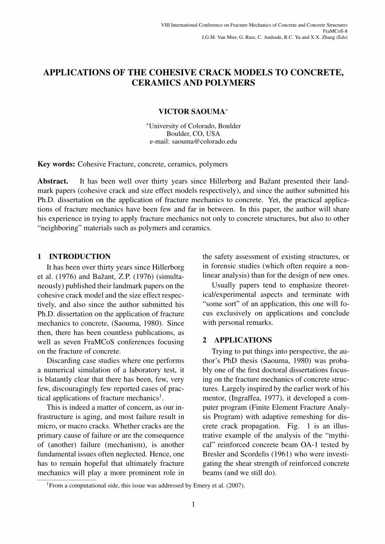
thor’s PhD thesis (Saouma, 1980) was proba-bly one of the first doctoral dissertations focus-ing on the fracture mechanics of concrete struc-tures. Largely inspired by the earlier work of hismentor, (Ingraffea, 1977), it developed a com-puter program (Finite Element Fracture Analy-sis Program) with adaptive remeshing for dis-crete crack propagation. Fig. 1 is an illus-trative example of the analysis of the “mythi-cal” reinforced concrete beam OA-1 tested byBresler and Scordelis (1961) who were investi-gating the shear strength of reinforced concretebeams (and we still do).
1From a computational side, this issue was addressed by Emery et al. (2007).
1
Victor E. Saouma
Fig. 1(a) is a snap-shot of the mesh after 13crack propagation increments. The (crude) au-tomatic remeshing is evident, yet such an earlyanalysis yielded a reasonable nonlinear load-displacement curve, Fig. 1(b). Finally, a real-istic crack profile, consistent with ACI-318 pre-diction was obtained, Fig. 1(b).
Though this program was used for a cou-ple of subsequent years, when the opportunitycame, an entirely new program (Merlin) was de-veloped, (Saouma et al., 2010), and all resultspresented in this paper are based on it.
10/12/2010
(a) R/C beam OA-1
10/12/2010
(b) Non-Linear load displacement curve
10/12/2010
(c) Crack profile
Figure 1: Origial figures from the author’s PhD thesis in1982
In the following pages, practical examples offracture mechanics applications will be shown.The author has been involved in all those anal-ysis, and for obvious reasons structure names,locations, and specific details will be omitted.
2.1 Civil EngineeringFracture mechanics may be implicitly or ex-
plicitly used in concrete structures. Implicitlythrough code equations which account for thesize effect law (such as in the shear strengthequation). Unfortunately the most widely ref-erenced design code (ACI-318) has not yet rec-ognized the need for such a consideration. Thisabberation can only be attributed to the inabilityof the research community and the practicingworld in this country to properly communicateand understand each other.
What is more pertinent to the topic of thispaper are the explicit applications of fracturemechanics in real structures. Such applicationshave recently been made possible through theconsideration of the cohesive crack model incommercial codes such as Atena, or Diana withvarious degrees of sophistication. Descriptionof these applications is better left to others.
A daunting question (which we may havetried to avoid) is how relevant is fracture me-chanics (i.e. to which extent a 10% change inthe fracture energy GF would alter final results)to reinforced concrete structures when cracksare by definition anticipated to occur (in orderto mobilize the load carrying capacity of the re-inforcement) and cohesive stresses are negligi-bly small compared to those in the reinforce-ment. On the other hand, fracture mechanicscould address some of the finer points (such ascrack width, critical in nuclear) or massive un-reinforced concrete structures (dams) or zonesof limited shear reinforcement.
2.1.1 Dams
Dams have historically been catalysts forstructural analysis innovations. If many of usare aware that the first reported application ofthe finite element in civil engineering was pre-
2
Victor E. Saouma
cisely the fracture analysis of a concrete dam bySims et al. (1964), few know that one of the firstapplications of the finite differences was alsomasonry dams (Richardson, 1911) not to men-tion the numerous examples of dams in the firstedition of Zienkiewicz (1967).
In the US, the identification of so-called“Potential Failure Modes” (which often meanssome form of cacking/sliding) is engrained inrecent regulations (Federal Energy RegulatoryCommission, 2006). Conceptually, this is anal-ogous to the well accepted “Performance BasedDesign” (FEMA-349, 2000). Both paradigmswould allow engineers to consider spendingmore resources to achieve quantifiable higherperformance thereby reducing risk. Hence,the structural performance of critical structuressuch as dams, nuclear containment vessels, andoffshore structures, could be improved throughappropriate non-linear analysis provided that anappropriate model can be used. Indeed the au-thor has recently examined a merger of thosetwo approaches, Saouma et al. (2012).
The analysis of a massive lock and dam(Reich et al., 1994) did lead to a US ArmyCorps of Engineers Technical Letter (ArmyCorps of Engineers, 1993), which stipulatedthat [one]need(s) to perform a fracture mechan-ics based investigation prior to major rehabili-tation. Regretfully, it appears that this directivehas been escinded (lack of sufficient “expert”?).
Finally, putting things in perspective, it isimportant to realize that with dams one is deal-ing with very large concrete structures, that nomajor distinction is made between cracks andjoints (horizontal or vertical), and that “Achile’sheel” is the joint between rock and concrete.Hence, whereas we assume (in design) thatthose joints are perfectly closed, they constitutepotential cracks once they open.
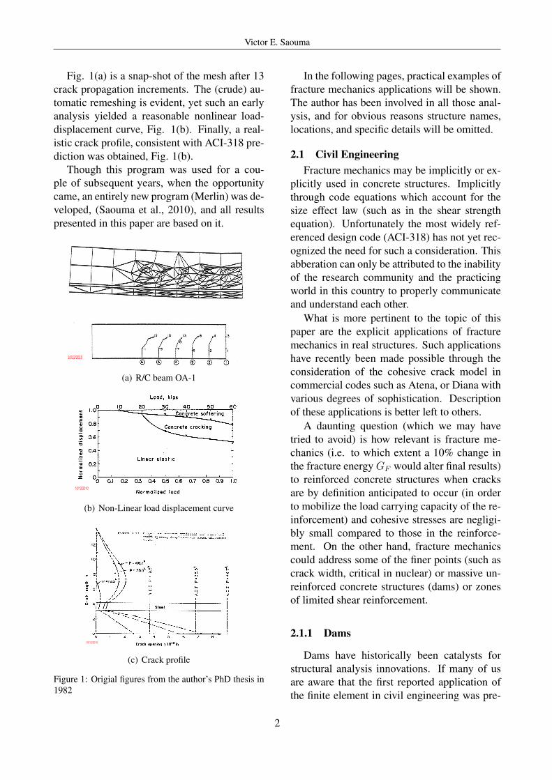
Seismic Safety Assessment of a Buttress DamThis first example, is an old buttress dam inJapan, Fig. 2(a). Though a relatively small one,there was some concern about its vulnerabilityto lateral seismic excitation, Fig. 2(b), speciallythat cracks where already present, Fig. 2(c).
To mitigate possible damage, a strengtheningplan was put together, Fig. 2(d). However, thesafety assessment of the dam did not accountfor the presence of mild steel reinforcement inthe buttresses which could have provided shearstrength through dowel effect. At this point, theauthor got involved in this project.
10/8/2010
(a) Buttress dam
10/11/2010
(b) Possible failure mode
Slab
Diagonal Cracks
Horizontal Cracks
10/11/2010
(c) Mappedcracks
φ 19mm
300mm
200mm
280mm
125mm
40
0m
m125mm
87.5mm
40mm
87.5mm
40mm
H- 125X125X6.5X9
10/8/2010
(d) Planned re-habilitation
10/8/2010
(e) 3D FE mesh;Joints highlighted inyellow
Figure 2: Buttress Dam
Modeling reinforcement across the multiplejoints was problematic, however joint model-ing through interface elements was simple. Assuch, an experimental program, Fig. 13,wasput together to determine a set of (fracturemechanics based) interface element propertiesequivalent to the one of a joint with reinforce-ment. Once determined, those properties wereassigned to all the joints and thus circumventedthe need to model dowel effects.
Finally, a 3D transient nonlinear fracture me-chanics based analysis was undertaken, Fig.2(e) and the dam was found to be sufficientlystrong to withheld the earthquake, and rehabili-tation plans shelved. This was one of the bestexample in which a reasonable investment inlaboratory tests and advanced analysis, yieldedsubstantially larger savings in unnecessary re-habilitation costs.
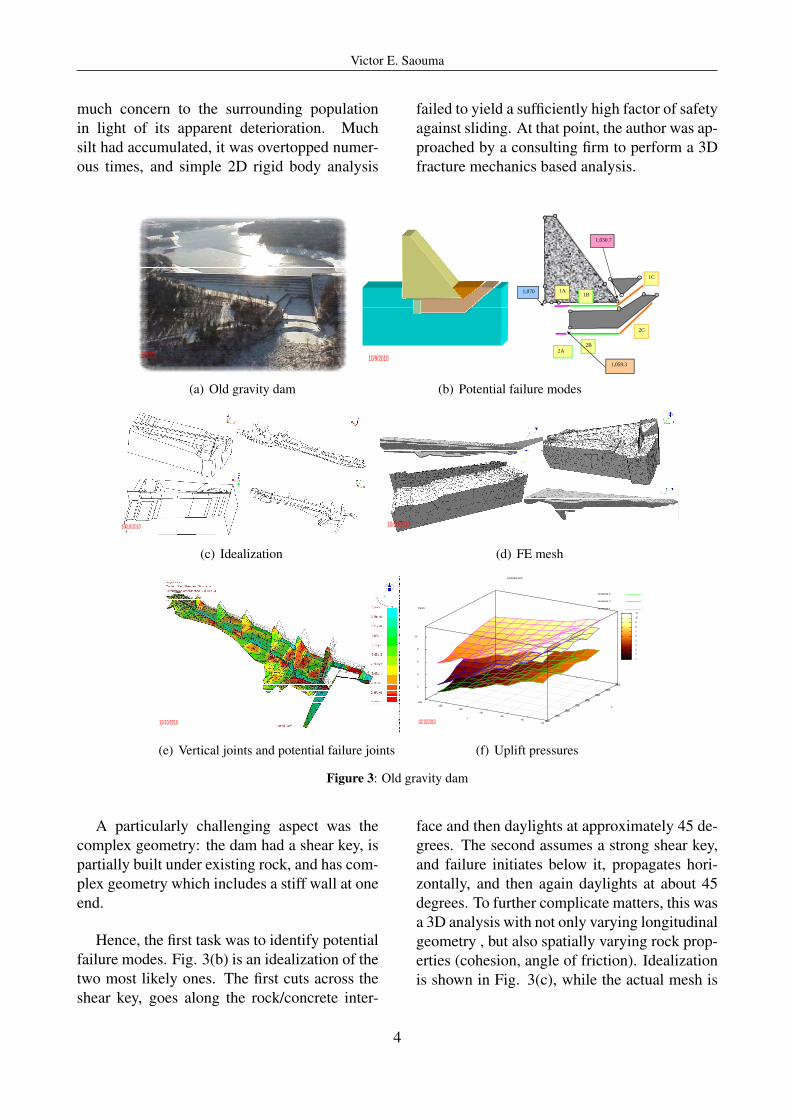
Safety Assessment of a Complex GravityDam This old gravity dam, Fig. 3(a), raised
3
Victor E. Saouma
much concern to the surrounding populationin light of its apparent deterioration. Muchsilt had accumulated, it was overtopped numer-ous times, and simple 2D rigid body analysis
failed to yield a sufficiently high factor of safetyagainst sliding. At that point, the author was ap-proached by a consulting firm to perform a 3Dfracture mechanics based analysis.
10/9/2010
(a) Old gravity dam
1,059.3
2A
1B
2B
2C
1C
1A1,070
1,030.7
10/9/2010
(b) Potential failure modes
10/10/2010
(c) Idealization
10/10/2010
(d) FE mesh
10/10/2010
(e) Vertical joints and potential failure joints
1
2
3
4
5
6
7
8
9
10
11
composite plot
Increment 2
Increment 3
Increment 4
-140-120
-100-80
-60-40
-20
Y1460
1480
1500
1520
1540
1560
1580
1600
X
2
4
6
8
10
Values
10/10/2010
(f) Uplift pressures
Figure 3: Old gravity dam
A particularly challenging aspect was thecomplex geometry: the dam had a shear key, ispartially built under existing rock, and has com-plex geometry which includes a stiff wall at oneend.
Hence, the first task was to identify potentialfailure modes. Fig. 3(b) is an idealization of thetwo most likely ones. The first cuts across theshear key, goes along the rock/concrete inter-
face and then daylights at approximately 45 de-grees. The second assumes a strong shear key,and failure initiates below it, propagates hori-zontally, and then again daylights at about 45degrees. To further complicate matters, this wasa 3D analysis with not only varying longitudinalgeometry , but also spatially varying rock prop-erties (cohesion, angle of friction). Idealizationis shown in Fig. 3(c), while the actual mesh is
4

Victor E. Saouma
shown in Fig. 3(d), and the joints (deformedshapes) are in Fig. 3(e).
Given the complex geometry, it was criticalto ensure that the mesh was indeed well put to-gether. This was critical as if two nodes acrossa potential failure modes are not connected byan interface element (i.e. tightly coupled), thenno failure would occur (albeit close examina-tion of the deformed shape and stress contourwould reveal an irregularity).
Another complexity is the ability to adjustuplift pressures automatically as the crack de-velop, and most importantly translate the resultsof a finite element analysis into a safety factoragainst sliding. The first was addressed by thecomputer program, and Fig. 3(f) is a graphi-cal representation of the 3D uplift distributionbetween two parallel vertical joints in terms ofthe hydrostatic pressure. The second is to com-pute the safety factor. In 2D hand calculations,the safety factor can be easily determined fromSF=cLuncr + ΣFv tanφ/ΣFh. In the 3D analy-sis, this requires special attention.
Seismic Safety of an Arch Dam Dams areinteresting structures. In the simplest cases,hand calculations are often enough to assess thesafety of a gravity dam. At the other end of thespectrum the seismic analysis of an arch dammay very well be amongst the most complexstructural analysis one can undertaken.
10/8/2010
(a) Dam
10/8/2010
(b) Interface Elements
Figure 4: Ach Dam
What is most striking in the following analy-sis, Fig. 4(a) is the extensive use of fracture me-chanics based interface elements to model ver-tical joints, and the rock-concrete interface, Fig.4(b). At first those joints are “zipped” together,and they open or slide when certain failure cri-teria are met. It should be noted that there is no
need for adaptive remeshing in these analysisas (most often) it is unlikely that new crack willdevelop in the concrete, since the joints consti-tute “fuses” which would open first and redis-tribute the stresses.
Dam with AAR Many old concrete structuressuffer from alkali aggregate reactions (AAR)which result in volumetric expansion. Whereasthis may be merely a nuisance for small struc-tures, it is of major concern in massive concreteones as the constrained expansion is likely toresult in structural cracking, inability to operatespillway gates, or worst yet misalignment of theturbines.
10/11/201010/11/2010
(a) Arch dam suffering from AAR
10/11/2010
(b) Finite element mesh
10/11/2010
(c) InternalStress con-tour plots
10/11/2010 10/11/2010
(d) Observed cracks along inter-nal the gallery and inside a bore-hole
Distance_from_crack_beginning
-0.0005 0
0.0005 0.001
0.0015 0.002
0.0025 0.003
0.0035 0.004
0.0045 0.005
0 2 4 6 8 10 12 14 16 18
increment 120
increment 121
increment 122
increment 123
increment 124
increment 125
-0.002 0
0.002 0.004 0.006 0.008 0.01
0.012 0.014
increment 120
increment 121
increment 122
increment 123
increment 124
increment 125
-12 -10 -8 -6 -4 -2 0 2
increment 120
increment 121
increment 122
increment 123
increment 124
increment 125
-2 -1 0 1 2 3 4 5 6 7 8
increment 120
increment 121
increment 122
increment 123
increment 124
increment 125
0 0.05 0.1
0.15 0.2
0.25 0.3
0.35 increment 120
increment 121
increment 122
increment 123
increment 124
increment 125
COD
CSD
σn
σt
Uplift
10/11/2010
(e) COD,CSD, uplift,σn and σt
Figure 5: Arch gravity dam suffering from AAR
AAR is a very slow thermodynamicallydriven reaction, and many years (over 20) maypass before the dam instrumentation can withcertainty indicate that we are in presence ofan irreversible deformation (typically upstream,and a crest elevation).Though nothing can stopthis reaction, it is of paramount importance fordam owner to assess the evolution (kinetics) of
5
Victor E. Saouma
the swelling with appropriate models, (Saoumaand Perotti, 2006).
Fig. 5(a) is an arch dam suspected of suffer-ing from AAR (it turned out not to be AAR butanother chemically induced reaction in the con-crete which results in a volumetric expansiontoo). Fig. 5(b) is the finite element mesh used.It should be noted that vertical joints were notmodeled, however it was deemed indispensableto model the rock concrete interfaces with frac-ture mechanics based interface elements. Fig.5(c) shows the internal stresses, and we notethe zone of high tensile stresses in the centerwhich may result in some hidden cracks. Indeeda crack was observed along the gallery, and aborehole drilled to determine its extent, Fig.5(d), as it had not “daylighted” on the down-stream face (yet). More details can be found in(Saouma et al., 2007).
2.1.2 Nuclear Reactor Containment Vessels
Another major civil infrastructure of whichcracking we should be concerned for obviousreasons are nuclear reactor containers. Indeed,the major design constraint is not strength butserviceability, i.e. no leakage should occur,and thus “no cracks allowed” This is ensuredthrough occasional Internal Pressurization Testswhere the inside of the container is pressurizedup to around 60 psi, and possible leaks identi-fied.
Another major concern with nuclear reactoris the (often unanticipated) cost of decommis-sioning. As such, many utility companies findit more cost effective to seek NRC’s approvalfor life extension from the usual 25-30 years lifespan to well over 50 years, (Graves et al., 2011).A major cost associated with this life extensionis the replacement of massive steam generator(SGR) as those become so embrittled throughradiation exposure, that repair is no longer anoption, and full replacement is a must.
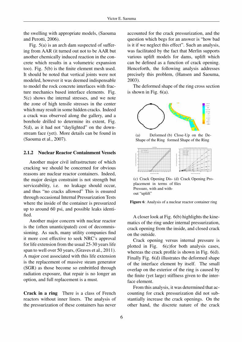
Crack in a ring There is a class of Frenchreactors without inner liners. The analysis ofthe pressurization of these containers has never
accounted for the crack pressurization, and thequestion which begs for an answer is “how badis it if we neglect this effect”. Such an analysis,was facilitated by the fact that Merlin supportsvarious uplift models for dams, uplift whichcan be defined as a function of crack opening.Henceforth, the following analysis addressesprecisely this problem, (Hansen and Saouma,2003).
The deformed shape of the ring cross sectionis shown in Fig. 6(a).
(a) DeformedShape of the Ring
(b) Close-Up on the De-formed Shape of the Ring
0 0.2 0.4 0.6 0.8 1 1.2 1.4 1.6 1.8 2 2.2 2.4 2.6 2.8 3
Internal Pressure [MPa]
0
5
10
15
20
25
30
35
Cra
ck O
peni
ng D
ispl
acem
ent [
mm
]
No UpliftWith Uplift
Inside Ring
(c) Crack Opening Dis-placement in terms ofPressure, with and with-out “uplift”
0 0.2 0.4 0.6 0.8
Distance from outside [m]
0
5
10
15
20
25
30
35
Cra
ck O
peni
ng D
ispl
acem
ent [
mm
]
1.25 MPa1.5 MPa2.0 MPa2.5 MPa3.0 MPa
Crack Opening Displacement Profiles in Terms of Internal Pressure
(d) Crack Opening Pro-files
Figure 6: Analysis of a nuclear reactor container ring
A closer look at Fig. 6(b) highlights the kine-matics of the ring under internal pressurization,crack opening from the inside, and closed crackon the outside.
Crack opening versus internal pressure isplotted in Fig. 6(c)for both analysis cases,whereas the crack profile is shown in Fig. 6(d).Finally Fig. 6(d) illustrates the deformed shapeof the interface element by itself. The smalloverlap on the exterior of the ring is caused bythe finite (yet large) stiffness given to the inter-face element.
From this analysis, it was determined that ac-counting for crack pressurization did not sub-stantially increase the crack openings. On theother hand, the discrete nature of the crack
6
Victor E. Saouma
model, did provide with a more realistic esti-mate for the crack opening displacement thana smeared crack model. As mentioned earlier,this estimate of the COD is critical as it providerequired information to assess the container per-meability to gas leak.
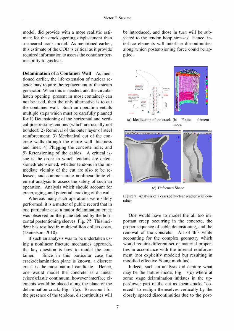
Delamination of a Container Wall As men-tioned earlier, the life extension of nuclear re-actor may require the replacement of the steamgenerator. When this is needed, and the circularhatch opening (present in most container) cannot be used, then the only alternative is to cutthe container wall. Such an operation entailsmultiple steps which must be carefully plannedfor:1) Detensioning of the horizontal and verti-cal prestressing tendons (which are usually notbonded); 2) Removal of the outer layer of steelreinforcement; 3) Mechanical cut of the con-crete walls through the entire wall thicknessand liner; 4) Plugging the concrete hole; and5) Retensioning of the cables. A critical is-sue is the order in which tendons are deten-sioned/retensioned, whether tendons in the im-mediate vicinity of the cut are also to be re-leased, and commensurate nonlinear finite el-ement analysis to assess the safety of such anoperation. Analysis which should account forcreep, aging, and potential cracking of the wall.
Whereas many such operations were safelyperformed, it is a matter of public record that inone particular case a major delamination crackwas observed on the plane defined by the hori-zontal postentioning sleeves, Fig. ??. This inci-dent has resulted in multi-million dollars costs,(Danielson, 2010).
If such an analysis was to be undertaken us-ing a nonlinear fracture mechanics approach,the key question is how to model the con-tainer. Since in this particular case thecrack/delamination plane is known, a discretecrack is the most natural candidate. Hence,one would model the concrete as a linear(visco)elastic continuum, however interface el-ements would be placed along the plane of thedelamination crack, Fig. 7(a). To account forthe presence of the tendons, discontinuities will
be introduced, and those in turn will be sub-jected to the tendon hoop stresses. Hence, in-terface elements will interlace discontinuitiesalong which postentsioning force could be ap-plied.
Tendons not
released
Te
nd
on
s n
ot
rele
ase
d
Tendons
releasedInterface Elements;
Based on Hillerborg’s
model, will crack only
if tensile stress
exceeds the tensile
strength; No bonds
between
conduits
and
concrete
Co
nc
rete
Co
nc
rete
X
Y
Free X
Fixed y
Tractions due to
Postensioning
cables; Applied
as uniform load
10/5/2010
(a) Idealization of the crack
10/9/2010
(b) Finite elementmodel
10/9/2010 10/9/2010
(c) Deformed Shape
Figure 7: Analysis of a cracked nuclear reactor wall con-tainer
One would have to model the all too im-portant creep occurring in the concrete, theproper sequence of cable detensioning, and theremoval of the concrete. All of this whileaccounting for the complex geometry whichwould require different set of material proper-ties in accordance with the internal reinforce-ment (not explicitly modeled but resulting inmodified effective Young modulus).
Indeed, such an analysis did capture whatmay be the failure mode, Fig. 7(c) where atsome stage delamination initiates in the up-per/lower part of the cut as shear cracks “co-erced” to realign themselves vertically by theclosely spaced discontinuities due to the post-
7
Victor E. Saouma
tensioning sleeves.
2.1.3 Massive R/C Support
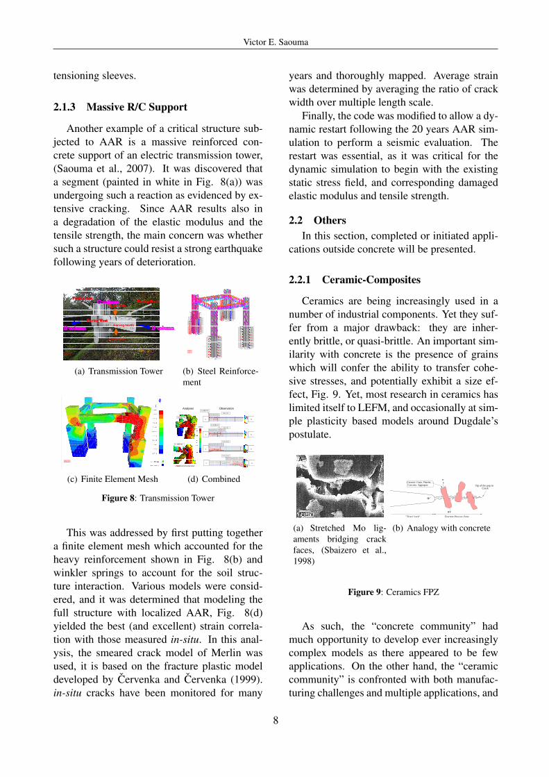
Another example of a critical structure sub-jected to AAR is a massive reinforced con-crete support of an electric transmission tower,(Saouma et al., 2007). It was discovered thata segment (painted in white in Fig. 8(a)) wasundergoing such a reaction as evidenced by ex-tensive cracking. Since AAR results also ina degradation of the elastic modulus and thetensile strength, the main concern was whethersuch a structure could resist a strong earthquakefollowing years of deterioration.
Facing North
Facing South
Facing West
Facing EastC-column
B-column
Lower side
Upper side
D-column
10/8/2010
(a) Transmission Tower
10/8/2010
(b) Steel Reinforce-ment
10/8/2010
(c) Finite Element Mesh
C脚C脚 D脚D脚
4.40
E-03
1.73
E-04
1.87
E-04
1.33
E-04
1.67
E-04
1.73
E-04
1.73
E-04
8.00
E-05
C脚C脚 D脚D脚
4.33
E-04
5.00
E-05
4.00
E-04
7.00
E-04
4.67
E-04
8.33
E-04
7.67
E-04
6.67
E-04
9.00
E-04
2.33
E-04
2.07
E-04
5.33
E-05
C脚C脚 D脚D脚
1.53
E-03
2.40
E-03
2.00
E-04
3.33
E-04
4.33
E-04
3.67
E-04
3.67
E-04
3.33
E-04
3.67
E-04
2.00
E-04
6.67
E-05
D脚D脚 C脚C脚
1.33
E-04
1.67
E-04
2.93
E-04
3.80
E-04
5.33
E-04
7.67
E-04
1.30
E-03
1.20
E-03
3.33
E-04
2.17
E-03
2.10
E-03
6.67
E-05
3.33
E-05
解析結果との比較
Upper side
Lower side
Facing North
Facing South
C
C
C
C
D
D
D
D
4.67E-03
1.18E-03
(MPa)
Maximum principal strain
Analyses Observation4.40E-03
9.00E-04
10/8/2010
(d) Combined
Figure 8: Transmission Tower
This was addressed by first putting togethera finite element mesh which accounted for theheavy reinforcement shown in Fig. 8(b) andwinkler springs to account for the soil struc-ture interaction. Various models were consid-ered, and it was determined that modeling thefull structure with localized AAR, Fig. 8(d)yielded the best (and excellent) strain correla-tion with those measured in-situ. In this anal-ysis, the smeared crack model of Merlin wasused, it is based on the fracture plastic modeldeveloped by Cervenka and Cervenka (1999).in-situ cracks have been monitored for many
years and thoroughly mapped. Average strainwas determined by averaging the ratio of crackwidth over multiple length scale.
Finally, the code was modified to allow a dy-namic restart following the 20 years AAR sim-ulation to perform a seismic evaluation. Therestart was essential, as it was critical for thedynamic simulation to begin with the existingstatic stress field, and corresponding damagedelastic modulus and tensile strength.
2.2 OthersIn this section, completed or initiated appli-
cations outside concrete will be presented.
2.2.1 Ceramic-Composites
Ceramics are being increasingly used in anumber of industrial components. Yet they suf-fer from a major drawback: they are inher-ently brittle, or quasi-brittle. An important sim-ilarity with concrete is the presence of grainswhich will confer the ability to transfer cohe-sive stresses, and potentially exhibit a size ef-fect, Fig. 9. Yet, most research in ceramics haslimited itself to LEFM, and occasionally at sim-ple plasticity based models around Dugdale’spostulate.
(a) Stretched Mo lig-aments bridging crackfaces, (Sbaizero et al.,1998)
ο
Crack
Φ
σ
σ
Tip of the pop in
Fracture Process Zone"True Crack"
Concrete: AggregateCeramic: Grain, Platelet, ...
(b) Analogy with concrete
Figure 9: Ceramics FPZ
As such, the “concrete community” hadmuch opportunity to develop ever increasinglycomplex models as there appeared to be fewapplications. On the other hand, the “ceramiccommunity” is confronted with both manufac-turing challenges and multiple applications, and
8
Victor E. Saouma
as such may not have developed models of thesame sophistication as the one developed for themore mundane concrete material.
Though not specifically addressing a prac-tical application, this section was inserted tohighlight the potential cross-fertilization poten-tial between those two “communities”.
Hence, the objective was to explore thepossibility of applying concrete models to ce-ramics, (Saouma et al., 2002). This was ac-complished in performing a nonlinear frac-ture mechanics analysis (based on Hillerborg’smodel) of the experimental tests of Sbaizeroet al. (1998) who tested Rectangular bars 3mmx4mm x20mm (B x W x L)with an a/W of0.5. Cohesive crack parameters were first ad-justed to yield comparable load deformationcurves, and then those were frozen ana analy-sis of different specimen sizes performed. Thisresulted in a crisply defined size effect, Fig.10(a). This is important as ceramics are usedin many different applications of varying sizes,Fig. 10(b) and as such size effect adjusted prop-erties should be used.
0.1 0.5 1 5 10
dd0
0.2
0.3
0.5
0.7
1
snBft
(a) Size Effect inAl2O3/20%Mo
Electronic Components
log (d/do)
log
(
σ
/σ0)
12
Turbine Blades
Engine Parts
Non Linear Linear Elastic
Fracture MechanicsPlasticity
Cutting Tools
(b) Size effect of ceram-ics
Figure 10: Nonlinear fracture mechanics simulation ofceramics
More recent studies, (Saouma et al., 2006)looked at the presence of residual stresses in ce-ramics, and the effect of physical transforma-tion on increased fracture toughness, (Saoumaet al., 2005).
2.2.2 Polymers
The last application focuses on polymersused for solid rocket propellants. A compos-ite solid rocket propellant is generally made of
a saline oxidizer, such as ammonium perchlo-rate, and a rubbery binder, such as Polybuta-diene, which acts as a fuel. Most rockets to-day use AP and Hydroxyl-Terminated PolyBu-tadiene, mixed with other minor but fundamen-tal constituents. The salt is milled in one, twoor three different grain sizes, and mixed withthe liquid HTPB. Hardener, Bonding Agent andCatalyser are then added, and the propellant iscast in the rocket case, generally made of somehigh-performance steel alloy or of compositematerial. A mandrel shapes the propellant sur-face. The motor is cured at high temperature inan oven, and the propellant solidifies, becominga rubber-like, filled elastomer. However, a criti-cal step is the extraction of the mandrel, Fig. ??as it may results in microcracks at the bore, Fig.11(a).
10/10/2010
(a) Internal crack
10/10/2010
(b) Uneven combus-tion
10/10/2010
(c) Crack bridging
10/10/2010
(d) Fracture process zone
a FPZ
Llig
p
p
10/10/2010
(e) Simplified 2Dmodel
10/13/2010
(f) Finite elementmesh; Deformedshape
Figure 11: Fracture of polymers
In the presence of a crack, binder filaments
9
Victor E. Saouma
bridge the crack partially connecting the twosides, the bonding agent anchors the oxidizerparticles to the binder with strong bonds, Fig.?? and confers higher toughness to the mate-rial, generating crack bridging through binderanchoring at two opposite oxidizer grains, Fig.11(c). Hence, along a portion of the crack,there is a transfer of stress through the stretchedbinder, giving rise to a fracture process zone,Fig. 11(d). Another great analogy with con-crete, and a prime candidate for nonlinear frac-ture mechanics.
Should there be a crack, the mechani-cal/thermal stress may cause crack growth re-sulting in additional surface area. The risk isthat there would be combustion inside the crack,Fig. 11(b) producing pressures much higherthan the designed maximum pressure resultingin the rocket explosion.
This is not an academic exercise, as indeedthere has been a motor explosion of a Titan IVPQM, (Chang et al., 1995). Since then, fracturemechanics to predict the service life of a motorand the determination of the critical crack sizeas an acceptance criterion for high-valued SRM(such as the Titan IV boosters), has been par-tially published, (Liu, 2003).
Whereas most of the early fracture mechan-ics applications were driven by LEFM, therewere only timid attempts to use the more ap-propriate cohesive crack model. In light of theabove, an experimental program was first set upto determine the fracture energy of solid pro-pellants, Sect. 3.3, (Tussiwand et al., 2006),and then numerical simulation using the ficti-tious crack model were undertaken, Fig. 11(f).
This work is currently being extended tocouple the nonlinear fracture mechanics codewith the one which simulates the combustion.Hence at each time step, the updated pressureand crack profile are passed to the stress analy-sis code from the combustion one.
3 UNDEPINNINGS; EXPERIMENTALWORK
The previously presented applications couldnot have been achieved by merely using a com-
puter program as a “black box”, and withouta good grasp of both the physics of the prob-lem and first principles. Furthermore, in manycases, models had to be based on proper testing,and finally computer models must be validated.
Henceforth, this last section will brieflypresent the underpinnings of the applicationspresented. Any complex nonlinear, fracturemechanics based, analysis must rely on propermodels (as described above), and those in turnmust rely on proper experimental tests. Thissection will detail two such set of experiments.
3.1 ConcreteFirst, large scale tests with specimens as
large as 5’ and 3” maximum size aggregateswere tested, Fig. 12(a),
10/10/2010 10/10/2010
(a) Large Scale testing
10/10/2010
(b) Fluidfractureinteraction
10/9/2010
(c) Acceleratedcore fracturetest
10/10/2010 10/10/2010
(d) Shear crack under confine-ment
10/10/2010 10/10/2010
(e) Reverse cycle loading
Figure 12: Laboratory testing for concrete
to determine the fracture energy of “dam
10
Victor E. Saouma
concrete”, (Saouma et al., 1991). Direct tensiontests on 36x6 inch cross section specimens werealso conducted, (Slowik et al., 1996).
Since we have at the base of a dam a largeshear stress, the potential shear crack prop-agation was also investigated, Fig. 12(d),(Slowik and V.E., 1996). Then the interac-tion of fluid and fracture was investigated, Fig.12(b), to determine the variation of uplift pres-sures in terms of crack opening, (Bruhwiler andSaouma, 1995a) and (Bruhwiler and Saouma,1995b). Much later, the effect of reverse cyclicloading on the degradation of concrete rough-ness, Fig. 12(e), was experimentally derived,(Puntel and Saouma, 2008). Finally, as fracturemechanics is likely to be more widely used inthe context of structural assessment, one musttest concrete cores recovered from site. Fig.12(c) is such a test on an 8” core inside an envi-ronmental chamber at 80oC to accelerate creepfracture.
3.2 Project Specific Testing
Whereas laboratory tests are most often per-formed to determine generic models, at times,they can be project specific. In support ofthe analysis reported in Sect. 2.1.1, labora-tory tests were performed on large jointed con-crete blocks crossed by 19 mm smooth rebars.The objective being to determine the global re-sponse (which would account for the dowel ef-fect), and then determine a set of interface jointproperties which could provide a similar re-sponse prior to a full dam analysis. Fig. 13(a)describes the test, the actual specimen is shownin Fig. 13(b).
Imposed variable shear
displacement along X axis
76.2 cm
X
Y106.7 cm
25.4 cm
15 cm
Y
76.2
cm
Smooth bar, 19 mm
46.2
cm
15 cm
15 cm
Thickness
25.4 cm15 cm
10/8/2010
(a) Test scehmatic
10/8/2010
(b) Test Specimen
Figure 13: Project specific testing
3.3 PolymersThis last test is an illustration of the cross-
fertilization between concrete and other mate-rial. Fig. 14(a) is a (enclosed) wedge splittingtest of a polymer used as a rocket propellant,and the fracture process zone is shown in Fig.14(a) where image analysis is used to determine(and control) crack openings. Finally Fig. 14(c)is the resulting master curve for the fracture en-ergy (which accounts for rate and temperatureof this visco-elastic material).
10/10/2010 (a) Wedge split-ting test of poly-mer
5.6 mm10/10/2010
(b) Fracture pro-cess zone
Fracture energy master curve
0
5
10
15
20
25
-5 0 5 10log( COD'aT )
GF,
mJ/
mm
2
GF, measured
load case conditions
10/10/2010
(c) Master curve
Figure 14: Fracture of polymers
3.4 Centrifuge Based ValidationsFinally, any finite element program must be
validated. Though it is customary to validatea program by reanalyzing the very same testsfrom which the constitutive model was (implic-itly or explicitly)derived, this is barely accept-able. In our case, some aspects of Merlin ca-pabilities were assessed through centrifuge testsof a dam model subjected to varying hydrostaticload, (Gillan et al., 2004). Then a more am-bitious test was performed by dynamically ex-citing a dam model inside a centrifuge, (Uchitaet al., 2005).
Fig. 15(a) is the large centrifuge of ObayashiCorporation in Tokyo where the test was per-formed. Fig. 15(b), shows the dam model(1/30th scale). Pre-test calculations were madeby Merlin, and Fig. 15(c) is an illustration ofthe crack and location of some of the instru-ments. Accelerometers were mounted at thebase and the crest. The dam was subjected toa series of 6 increasing harmonics. Measuredand predicted crest accelerations are shown inFig. 15(d), and the transfer functions in Fig.15(e). From the last two figures, it was evidentthat merlin captured well the nonlinear dynamic
11
Victor E. Saouma
response of the dam, and thus provided addi-tional confidence in its use for nonlinear tran-sient fracture mechanics analysis.
10/14/2010
(a) Obayashicentrifuge
0.96m
0.15m
0.20m 0.15m 1:1.0
1:0.6 0.60m
0.05m
10/14/2010
(b) Dammodel
ST-18
ST-19
ST-20
ST-21
ST-22
10/14/2010
(c) Instru-mentation andcrack
-1400-1000
-600-200200600
100014001800
0.0 0.2 0.4 0.6 0.8 1.0 1.2
Time (sec)
Acce
lera
tion
(m/s
ec2 )
解析
実験
-500
-300
-100
100
300
0.0 0.2 0.4 0.6 0.8 1.0 1.2
Time (sec)
Acce
lera
tion
(m/s
ec2 )
解析
実験
Analysis
Experiment
10/14/2010
(d) Dynamic re-sponses
02468
10121416
200 250 300 350 400 450 500
周波数 (Hz)
増幅
率
解析
実験Analysis
Experiment
10/14/2010
(e) Transferfunctions
Figure 15: Centrifuge/shake table tests for Merlin valida-tion
4 Final RemarksBased on the experience gained through this
reported work, the following needs are identi-fied:1. The engineering professions must trust theacademic world in helping them address com-plex problems as is often the case in Europe andJapan.2. ACI-318 should seriously consider impact ofsize effect laws on some of its provisions (shearequation in particular).3. University professors should broaden theirresearch goals to address complex interdisci-plinary, multi-scale practical problems. Fun-damental research will always be essential, andshould be recognized as such. It is presumptu-ous to think that one single narrow engineeringdiscipline (such as fracture mechanics) by itselfcan help us solve societal problems.4. Fracture mechanics is much more relevantto assess the integrity of existing structures thanthe design of new ones. Henceforth, core basedlaboratory specimens should be favored overprismatic ones for Gf testing.5. One critical research need is creep fracture.The only major such tests was performed about20 years ago by Zhou (1992).
6. A certification program to “validate” com-puter codes with nonlinear fracture mechanicscapabilities should be put in place. Such an ef-fort could be spearheaded by NRC, FEMA orEPRI.7. Reliable (fracture mechanics based or not)non-linear analysis of reinforced concrete re-mains a challenge. As evidenced by numerousbenchmarks, even the simple analysis of a R/Cbeam can yields widely different results.8. Though numerical modeling was not ad-dressed in this paper, the author feels “vindi-cated” that the discrete crack model pioneeredby Ingraffea and Saouma over thirty years ago,is back in favor, albeit under different form.
5 CONCLUSIONSThirty years after his dissertation on the ap-
plication of fracture mechanics to concrete, thispaper was an attempt to summarize some ofthe practical applications undertaken by the au-thor. Within “traditional” civil engineering,they covered concrete dams, nuclear reactorcontainment vessels, massively reinforced con-crete structures. Other application to ceramicsand polymers were also presented. Also pre-sented are some of the innovative testings whichmade those analysis possible.
6 ACKNOWLEDGMENTThe author would like to first, and foremost,
thank his Ph.D. advisor, Prof. A. Ingraffea, whosupervised his dissertation, over thirty yearsago.
Sincere thanks are also extended to a few“visionary persons from the practical word whocame to accept fracture mechanics. This in-cludes Howard Boggs (Bureau of Reclamation,Ret), Chong Chiu (PII), Doug Morris (EPRI),Giuseppe Tussiwand (Bayern Chemie), YusidoiUchita (TEPCO).
Last, but not least special thanks are tomy closest collaborators, colleagues who madeMerlin a reality, Jan Cervenka, Gay Hauss-mann, Ronald Reich, and Yoshinori Yagome.
Institutionally, the Electric Power ResearchInstitute (EPRI), and the Tokyo Electric Power
12
Victor E. Saouma
Company (TEPCO) financial support is grate-fully acknowledged.
ReferencesArmy Corps of Engineers: 1993, Fracture me-
chanics analysis of gravity lock monolith,ETL 1110-2-344, Department of the Army,US Army Corps of Engineers, Washington,D.C.
Bazant, Z.P.: 1976, Instability, ductility and sizeeffect in strain softening concrete, Journal ofEngng. Mech., ASCE 102(2), 331–344.
Bresler, B. and Scordelis, A.: 1961, Shearstrength of reinforced concrete beams, Jornalof the American Concrete Institute 60(1), 51–74.
Bruhwiler, E. and Saouma, V.: 1995a, Wa-ter fracture interaction in concrete; part ifracture properties, ACI Materials Journal92(3), 296–303.
Bruhwiler, E. and Saouma, V.: 1995b, Waterfracture interaction in concrete; part ii hydro-static pressures cracks, ACI Materials Jour-nal 92(4), 383–390.
Cervenka, J. and Cervenka, V.: 1999, Threedimensional combined fracture-plastic ma-terial model for concrete, 5th U.S. Na-tional Congress on Computational Mechan-ics, Boulder, CO.
Chang, I., Patel, N. R. and Yang, S.: 1995, Titaniv motor failure and redesign analyses, Jour-nal of Spacecraft and Rockets 32(4), 612–618.
Danielson, R.: 2010, Crack at crystal river nu-clear power plant explained.
Emery, J., Hochhalther, J. and Ingraffea, A.:2007, Computational fracture mechanics ofconcrete structures: A retrospective throughmultiple lenses, in A. Carpinteri, G. P.,G. Ferro and G. Plizzari (eds), Proceed-ings 6th International Conference on Frac-ture Mechanics of Concrete and Concrete
Structures (FraMCoS-VI), Taylor & Francis,Catania, pp. 3–15.
Federal Energy Regulatory Commission: 2006,Engineering guidelines for the evaluation ofhydropower projects, Technical report, Fed-eral Energy Regulatory Commission, Officeof Hydropower Licensing.
FEMA-349: 2000, Fema 349-action plan forperformance based seismic design, Techni-cal report, Federal Emergency ManagemtAgency.
Gillan, C., Saouma, V. and Shimpo, T.: 2004,Centrifuge tests of concrete dams, Interna-tional Journal of Water Power and Dam Con-struction pp. 38–41.
Graves, H., LePape, Y., Naus, D., Rashid,J., Saouma, V., Sheikh, A. and Wall, J.:2011, Extended Proactive Materials Degra-dation Analysis (PMDA) - Aging of Con-crete, Technical report, Oak Ridge NationalLaboratory. (J. Busby Program Director).
Hansen, E. and Saouma, V.: 2003, 3 d nonlinearfinite element/fracture mechanics analysis ofa pressurized nuclear reactor container ring,Nuclear Engineering and Design 225, 1–10.
Hillerborg, A., Modeer, M. and Petersson, P.:1976, Analysis of crack formation and crackgrowth in concrete by means of fracturemechanics and finite elements, Cement andConcrete Research 6(6), 773–782.
Ingraffea, A.: 1977, Discrete Fracture Propa-gation in Rocks: Laboratory Tests and FiniteElement Analysis, PhD thesis, University ofColorado.
Liu, C.: 2003, The application of fracture me-chanics to predict the critical initial cracklength, Technical Report AFRL-PR-ED-TP-2003-057, Edwards AFB CA Space and Mis-sile Propulsion Div.
Puntel, E. and Saouma, V.: 2008, Experimen-tal behavior of concrete joints under cyclic
13
Victor E. Saouma
loading, ASCE J. of Structural Engineering134(9), 1558–1568.
Reich, R., Saouma, V. and Chasten, C.: 1994,Fracture mechanics based analysis of a grav-ity lock monolith, Int. J. of Dam Engineering5(3).
Richardson, L.: 1911, The approximate arith-metical solution by finite differences of phys-ical problems involving differential equa-tions, with an application to the stresses in amasonry dam, Philosophical Transactions ofthe Royal Society, Series A. 210, 307–357.
Saouma, V.: 1980, Finite Element Analysis ofReinforced Concrete; a Fracture MechanicsApproach, PhD thesis, Cornell University,Department of Structural Engineering.
Saouma, V., Broz, J., Bruhwiler, E. and Boggs,H.: 1991, Effect of aggregate and specimensize on fracture properties of dam concrete,ASCE, Journal of Materials in Civil Engi-neering 3(3), 204–218.
Saouma, V., Chang, S. and Sbaizero, O.:2005, Numerical simulation of transforma-tion ZrO2-toughned AL2O3, European Jour-nal of Ceramics . Submitted.
Saouma, V., Chang, S. and Sbaizero, O.: 2006,Numerical simulation of thermal residualstress in mo- and feal−- toughened Al2O3,Composites Part B: Engineering 37, 550–555.
Saouma, V., Natekar, D. and Sbaizero, O.:2002, Nonlinear finite element analysisand size effect study of a metal-reinforcedceramics-composite, Materials Science andEngineering A 323, 129–137.
Saouma, V. and Perotti, L.: 2006, Constitu-tive model for alkali aggregate reactions, ACIMaterials Journal 103(3), 194–202.
Saouma, V., Perotti, L. and Shimpo, T.: 2007,Stress analysis of concrete structures sub-jected to alkali-aggregate reactions, ACI Ma-terials Journal 104(5), 532–541.
Saouma, V., Porter, K., Nuss, L. and Hariri, M.:2012, Performance based engineering designguidelines for concrete dams, Technical re-port, Enerjisa, Turkey. Draft eport.
Saouma, V., Cervenka, J. and Reich, R.:2010, Merlin finite element user’s man-ual, http://civil.colorado.edu/
˜saouma/pdf/users.pdf.
Sbaizero, O., Pezzotti, G. and Nishida, T.:1998, Fracture energy and R-curve behav-ior of Al2O3/Mo composites, Acta. Mater.46(2), 681–87.
Sims, F., Rhodes, J. and Clough, R.: 1964,Cracking in norfork dam, J. of the AmericanConcrete Institute .
Slowik, V., Saouma, V. and Thompson, A.:1996, Large scale direct tension test ofconcrete, Cement and Concrete Research26(6), 949–954.
Slowik, V. and V.E., S.: 1996, Behavior of rockconcrete interfaces in gravity dams, Techni-cal report, Electric Power Research Institute,Palo-Alto, CA. Final Research Report to beSubmitted by the University of Colorado.
Tussiwand, G., Saouma, V. and Terzenbach, R.:2006, Fracture mechanics of a solid rocketmotor using AP-HTPB based composite pro-pellant; part i material testing, Journal ofPropulsion and Power . Submitted for Publi-cation.
Uchita, Y., Shimpo, T. and Saouma, V.: 2005,Dynamic centrifuge tests of concrete dams,Earthquake Engineering and Structural Dy-namics 34, 1467–1487.
Zhou, F.: 1992, Time-dependent Crack Growthand Fracture in Concrete, PhD thesis, Divi-sion of Building Materials Lund Institute ofTechnology.
Zienkiewicz, O.: 1967, The Finite Element inStructural and Continuum Mechanics, firstedn, McGraw-Hill, London.
14


![Engineering Fracture Mechanics · 2020. 6. 2. · lems, including: the crack growth with frictional contact [33], cohesive crack propagation [34–36], stationary and growing cracks](https://img.dokumen.tips/doc/110x75/60cb969feb2e1a3a012238f6/engineering-fracture-mechanics-2020-6-2-lems-including-the-crack-growth-with.jpg)


![Fracture[1].mechanics saouma(2000)](https://img.dokumen.tips/doc/110x75/557d1455d8b42a6e4f8b46b2/fracture1mechanics-saouma2000.jpg)