Embed Size (px)
Citation preview
1
Applications of Bezier Clipping Method and Their Java Applets
Tomoyuki NishitaFaculty of Engineering, Fukuyama University,
985 Higashimura-cho, Fukuyama, 729-0292 Japan E-mail: [email protected]
AbstractDisplaying objects with high accuracy is important in CAGD and for thesynthesis of photo-realistic images. The representation of free-form surfacescan be classified into two: parametric surfaces such as Bezier patches, andimplicit surfaces like metaballs. We discuss display methods for both Bezierpatches and metaballs by using Bezier Clipping. Traditionally, polygonalapproximation methods have been employed to display parametric surfaces.This paper introduces various display methods for Bezier patches withoutpolygonal approximation. Bezier Clipping can be also applied to thefollowing: 1) curve/curve intersection, 2) curve/surface intersection, 3) scanconversion of curved regions such as outline fonts, 4) various lightingsimulations such as curved light sources and radiosity method. In order toshow the effectiveness of Bezier Clipping widely by using the Internet, we havecoded some of them(e.,g.,curve/curve intersection, metaballs) in Java language.The Bezier Clipping is very effective for displaying metaballs and metacircles(2D version of metaballs) and for the application of metaballs, we demonstraterealistic rendering of clouds, snow, smoke, and water droplets.
1. Introduction Effective rendering methods for curved surfaces are discussed here. Therepresentation of free-form surfaces can be classified into two categories:parametric surfaces and implicit surfaces. For the former, Bezier patches, B-spline patches, and NURBS are used. For the latter, algebraic surfaces and aset of density functions such as metaballs (or blobs) are used. This paperdiscusses the idea of Bezier clipping and its application to various renderingtechniques. In order to show the effectiveness of Bezier Clipping widely byusing the Internet, we have coded some of them in Java language. Bezier clipping can be applied to hidden line/surface removal of Bezierpatches. Bezier clipping can be also applied to raytracing of metaballs. TheBezier clipping technique can be applied not only to hidden line/surfaceremoval but also to various shading effects.
2. Basic Idea of Bezier Clipping
Bezier clipping is an iterative method which takes advantages of the convexhull property of Bezier curves, and iteratively clips away regions of the curvewhich don’t intersect the line. Thus we can refer to this method as an interval
2
Newton method. Bezier clipping converges more robustly with thepolynomial's solution than does Newton's method. This method was firstdeveloped for raytracing Bezier patches[Nishi90]. The advantages of this technique are as follows:
(1) Applicable to a high order of polynomial (and rational functions)(2) Robust(3) No initial guess necessary(4) All solutions within specified range(5) Minimum/maximum root available if necessary(6) Quick test for non-intersection
(7) High-degree Bezier function/curves solved by iterations using onlylinear equations (i.e., Bezier clipping uses only linear equations in eachiteration).
The Newton method is often used for numerical analysis, but it requires asuitable initial guess, and it is difficult to be sure of finding all solutions.Bezier clipping overcomes these problems. 2.1 Applications of Bezier ClippingThe following are applications of Bezier clipping.
(1) Root finder for polynomials(2) Basic geometric problems: curve/curve intersection[Seder90], curve
/surface or surface/surface intersection[Seder91](3) Hidden surface removal for parametric surfaces: raytracing[Nishi90],
scanline algorithm[Nishi91a], hidden line algorithm[Nishi92b](4) Hidden surface removal for metaballs[Nishi94a](5) Shading models: cylindrical light sources[Nishi92a], curved light sources
and radiosity[Nishi94b], optical effects on curved surfaces such ascaustics[Nishi94b] or water drops[Kaneda96], natural phenomena suchas clouds[Nishi96]
(6) 2-D computer graphics: scan conversion of curved regions, outline fonts[Nishi91b], brush strokes, watercolor painting[Nishi93a], morphing[Nishi93b], and metacircles( 2D version of metaballs).
As described above, Bezier clipping can be applied to many fields. Thispaper will focus on 3-D rendering, the details of (5) and (6) are omitted.
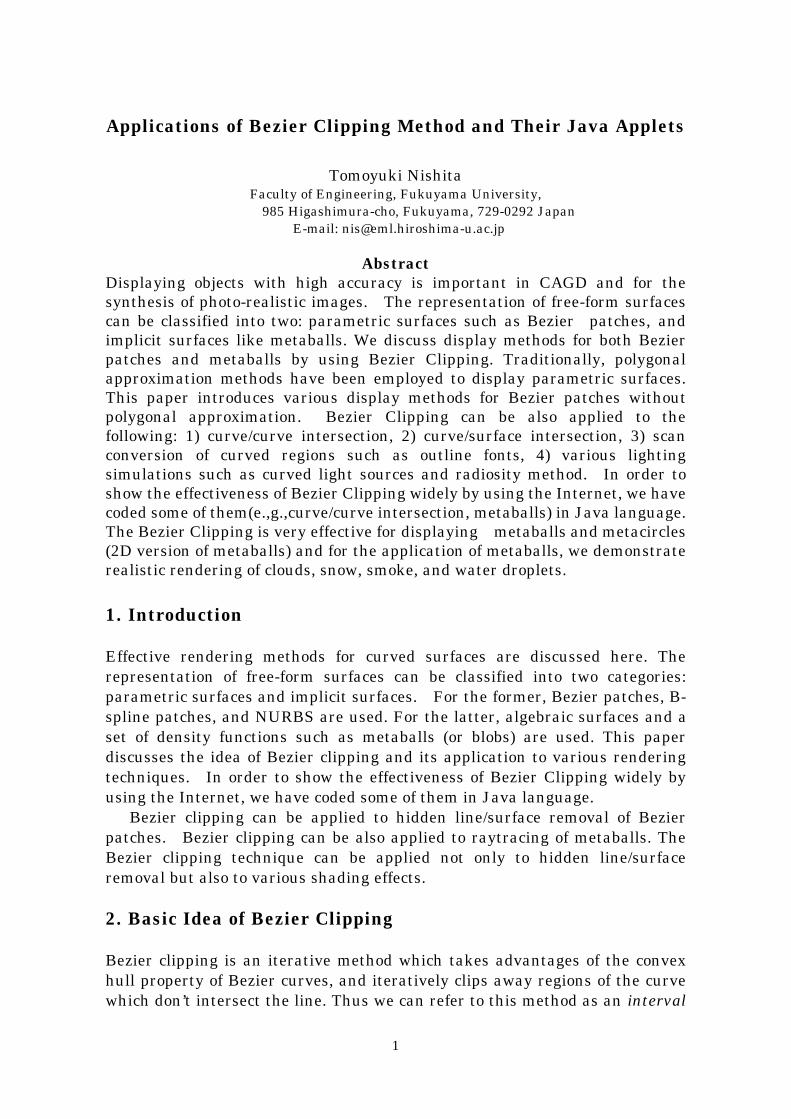
2.2 Solving to PolynomialsPolynomials can be converted to a Bezier curve. For example, a degree threepolynomial can be converted to the cubic Bezier function. Fig. 1(a) shows thepolynomial (f(x) = 24x3-42x2+2x+2) converted to the following a cubic Bezierfunction;
3
1.0
-2.0
-4.0
0.0
2.0
4.0
6.0
f
(1, -3)(2/3, -4)
(1/3, 6)
(0, 2)
maxt
(a) original
(b) after clipping
-2.0
-4.0
0.0
2.0
4.0
6.0
f
2/3
1/3
t
mint
2/31/3t
1.0
f0
f2
f1
f3
Fig.1 Solving to polynomial by Bezier clipping
f t f B tkk
k( ) ( )==
∑0
33 (1)
where (k/3,fk) (k=0,..,3) are control points of the Bezier function, and Bk3 is the
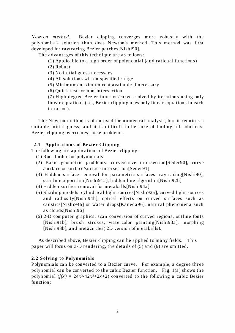
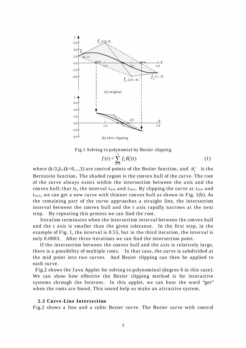
Bernstein function. The shaded region is the convex hull of the curve. The rootof the curve always exists within the intersection between the axis and theconvex hull; that is, the interval tmin and tmax. By clipping the curve at tmin andtmax, we can get a new curve with thinner convex hull as shown in Fig. 1(b). Asthe remaining part of the curve approaches a straight line, the intersectioninterval between the convex hull and the t axis rapidly narrows at the nextstep. By repeating this process we can find the root. Iteration terminates when the intersection interval between the convex hulland the t axis is smaller than the given tolerance. In the first step, in theexample of Fig. 1, the interval is 0.55, but in the third iteration, the interval isonly 0.0003. After three iterations we can find the intersection point. If the intersection between the convex hull and the axis is relatively large,there is a possibility of multiple roots. In that case, the curve is subdivided atthe mid point into two curves. And Bezier clipping can then be applied toeach curve. Fig.2 shows the Java Applet for solving to polynominal (degree 6 in this case).We can show how effective the Bezier clipping method is for interactivesystems through the Internet. In this applet, we can hear the word “get”when the roots are found. This sound help us make an attractive system.
2.3 Curve-Line IntersectionFig.2 shows a line and a cubic Bezier curve. The Bezier curve with control
4
points Pk(xk,yk) is expressed by the following equation.
x t x B tkk
k( ) ( )==
∑0
33 , y t y B tk
kk( ) ( )=
=∑
0
33 (2)
And the distance from any point (x,y) to the line is expressed by
d x y ax by c( , ) = + + (3)
By substituting x and y of the curve equation to the line equation, we canget the following Bezier function.
d t f B t
f ax by c
kk
k
k k k
( ) ( )=
= + +=
∑0
33
(4)
where fk is equivalent to the distance between the control point Pk and the line.Equation (4) is called distance function. (a,b) is the unit normal of line(a2+b2=1). Fig.1(a) shows the distance function expressed by the Bezierfunction. Parameter t at the intersection with the t-axis gives us theintersection between the line and the curve. Bezier clipping solves thisintersection.
P0
P1
P2
P3f1 f2
f3
f0
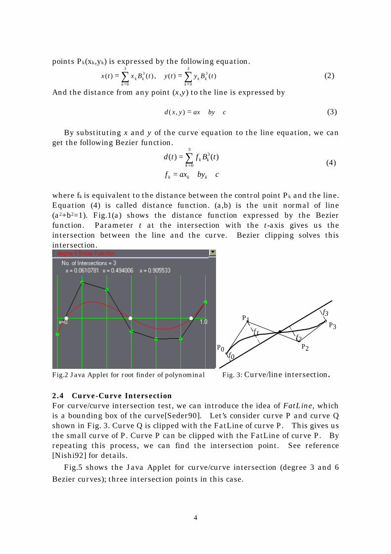
Fig.2 Java Applet for root finder of polynominal Fig. 3: Curve/line intersection.
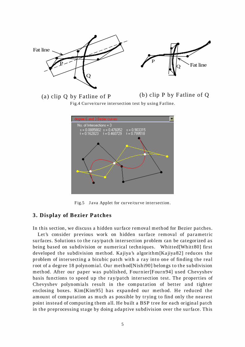
2.4 Curve-Curve IntersectionFor curve/curve intersection test, we can introduce the idea of FatLine, whichis a bounding box of the curve[Seder90]. Let’s consider curve P and curve Qshown in Fig. 3. Curve Q is clipped with the FatLine of curve P. This gives usthe small curve of P. Curve P can be clipped with the FatLine of curve P. Byrepeating this process, we can find the intersection point. See reference[Nishi92] for details. Fig.5 shows the Java Applet for curve/curve intersection (degree 3 and 6Bezier curves); three intersection points in this case.
5
Fat line
P
Q
(a) clip Q by Fatline of P (b) clip P by Fatline of Q
QP
Fat line
Fig.4 Curve/curve intersection test by using Fatline.
Fig.5 Java Applet for curve/curve intersection.
3. Display of Bezier Patches
In this section, we discuss a hidden surface removal method for Bezier patches. Let’s consider previous work on hidden surface removal of parametricsurfaces. Solutions to the ray/patch intersection problem can be categorized asbeing based on subdivision or numerical techniques. Whitted[Whitt80] firstdeveloped the subdivision method. Kajiya’s algorithm[Kajiya82] reduces theproblem of intersecting a bicubic patch with a ray into one of finding the realroot of a degree 18 polynomial. Our method[Nishi90] belongs to the subdivisionmethod. After our paper was published, Fournier[Fourn94] used Chevyshevbasis functions to speed up the ray/patch intersection test. The properties ofChevyshev polynomials result in the computation of better and tighterenclosing boxes. Kim[Kim95] has expanded our method. He reduced theamount of computation as much as possible by trying to find only the nearestpoint instead of computing them all. He built a BSP tree for each original patchin the preprocessing stage by doing adaptive subdivision over the surface. This
6
binary tree allows us to find which part of the subdivided patch is likely tocontain the nearest intersection from the viewpoint.
0
Lv
V ‚P
u
Lu
6
‚V
10
V0
8
9
v
1
P02
d02
d22
P20
P00
P22
d 00
-2
2
76
5
-8-9
-10
0
d
umax
umin
-1 u1
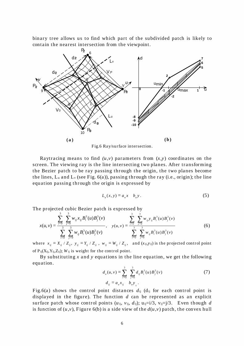
( a ) ( b )Fig.6 Ray/surface intersection.
Raytracing means to find (u,v) parameters from (x,y) coordinates on thescreen. The viewing ray is the line intersecting two planes. After transformingthe Bezier patch to be ray passing through the origin, the two planes becomethe lines, Lu and Lv (see Fig. 6(a)), passing through the ray (i.e., origin); the lineequation passing through the origin is expressed by
L x y a x b yu u u( , ) = + . (5)
The projected cubic Bezier patch is expressed by
x u v
w x B u B v
w B u B v
iij ij
ji j
iij
ji j
( , )
( ) ( )
( ) ( )= = =
= =
∑ ∑
∑ ∑0
3
0
33 3
0
3
0
33 3
, y u v
w y B u B v
w B u B v
i
ij ij
j
i j
i
ij
j
i j
( , )
( ) ( )
( ) ( )
= = =
= =
∑ ∑
∑ ∑0
3
0
33 3
0
3
0
33 3
(6)
where x X Zij ij ij= / , y Y Zij ij ij= / , w W Zij ij ij= / , and (xij,yij) is the projected control point
of Pij(Xij,Yij,Zij); Wij is weight for the control point. By substituting x and y equations in the line equation, we get the followingequation.
d u v d B u B vu
i
ij
j
i j( , ) ( ) ( )== =∑ ∑
0
3
0
33 3 (7)
d a x b yij u ij u ij= + .
Fig.6(a) shows the control point distances dij (dij for each control point isdisplayed in the figure). The function d can be represented as an explicitsurface patch whose control points (uij, vij, dij); uij=i/3, vij=j/3. Even though dis function of (u,v), Figure 6(b) is a side view of the d(u,v) patch, the convex hull
7
of the projected control points bounds the projection of the d patch. We canfind the range having intersections (see [umin, umax] in Fig. 6(b)) by this figure.This process of identifying values umin and umax which bound the solution set,and then subdividing off the regions u<umin and u > umax. In a similar manner,we define the process of Bezier clipping in parameter v. Our ray-patchintersection algorithm consists of alternately performing Bezier clipping in uand v. By repeating this process, we can get the small patch which is theintersection point.
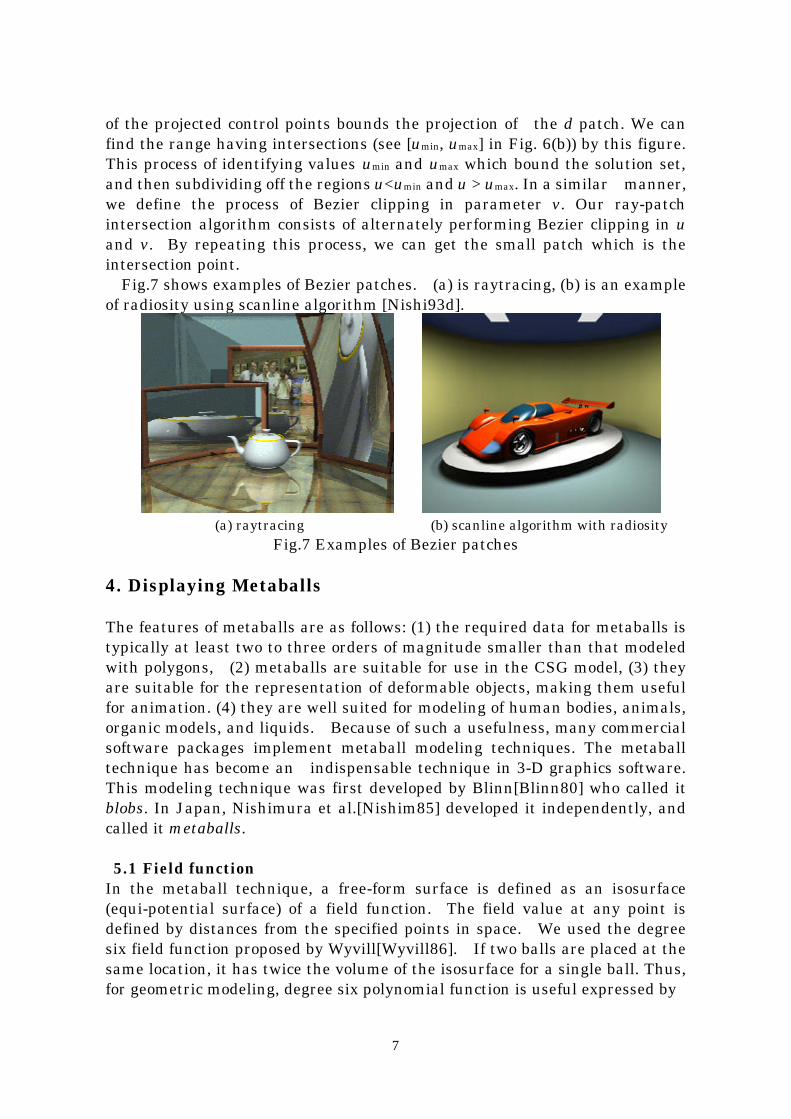
Fig.7 shows examples of Bezier patches. (a) is raytracing, (b) is an exampleof radiosity using scanline algorithm [Nishi93d].
(a) raytracing (b) scanline algorithm with radiosity
Fig.7 Examples of Bezier patches
4. Displaying Metaballs
The features of metaballs are as follows: (1) the required data for metaballs istypically at least two to three orders of magnitude smaller than that modeledwith polygons, (2) metaballs are suitable for use in the CSG model, (3) theyare suitable for the representation of deformable objects, making them usefulfor animation. (4) they are well suited for modeling of human bodies, animals,organic models, and liquids. Because of such a usefulness, many commercialsoftware packages implement metaball modeling techniques. The metaballtechnique has become an indispensable technique in 3-D graphics software.This modeling technique was first developed by Blinn[Blinn80] who called itblobs. In Japan, Nishimura et al.[Nishim85] developed it independently, andcalled it metaballs. 5.1 Field functionIn the metaball technique, a free-form surface is defined as an isosurface(equi-potential surface) of a field function. The field value at any point isdefined by distances from the specified points in space. We used the degreesix field function proposed by Wyvill[Wyvill86]. If two balls are placed at thesame location, it has twice the volume of the isosurface for a single ball. Thus,for geometric modeling, degree six polynomial function is useful expressed by
8
f rr
R
r
R
r
Ri
i i i
( ) ( ) ( ) ( )= − + − +4
9
17
9
22
916 4 2 (8)
where Ri is the radius of metaball i and r is the distance from a point to thecenter Pi(xi, yi, zi). For n metaballs, the shape of the curved surface is defined by the pointssatisfying the following equation.
f x y z q f Ti
i
n
i( , , ) = − ==∑
1
0 (9)
where T is a threshold, qi the density values at the center of metaball i.
f
f 1
d0
d3
d4
d5
0
-
A
viewpoint t
isosurface
d2
2f
si
d 1 d6
ray
tf 12
P0
P1
P2Pt
B C
T
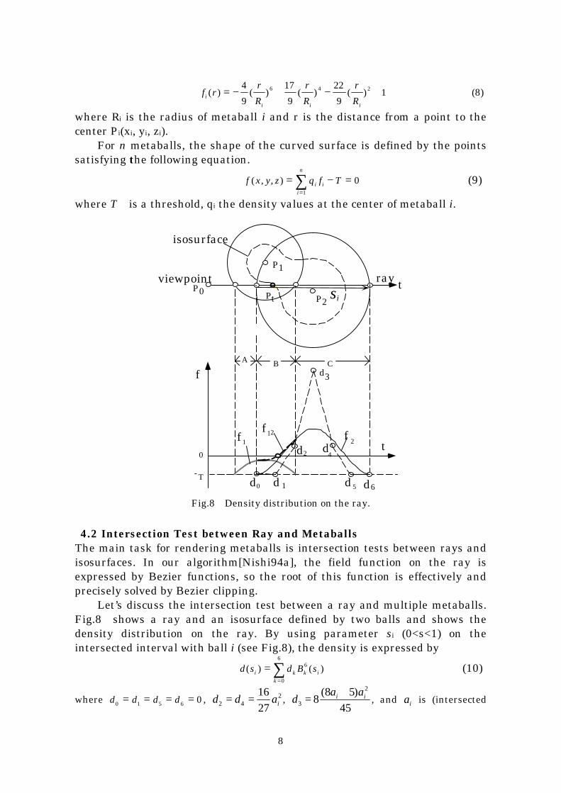
Fig.8 Density distribution on the ray.
4.2 Intersection Test between Ray and MetaballsThe main task for rendering metaballs is intersection tests between rays andisosurfaces. In our algorithm[Nishi94a], the field function on the ray isexpressed by Bezier functions, so the root of this function is effectively andprecisely solved by Bezier clipping. Let’s discuss the intersection test between a ray and multiple metaballs.Fig.8 shows a ray and an isosurface defined by two balls and shows thedensity distribution on the ray. By using parameter si (0<s<1) on theintersected interval with ball i (see Fig.8), the density is expressed by
d s d B si k k i
k
( ) ( )==
∑ 6
0
6
(10)
where d d d d0 1 5 6 0= = = = , d d ai2 4216
27= = , d
a ai i3
2
88 5
45=
+( ), and ai is (intersected
9
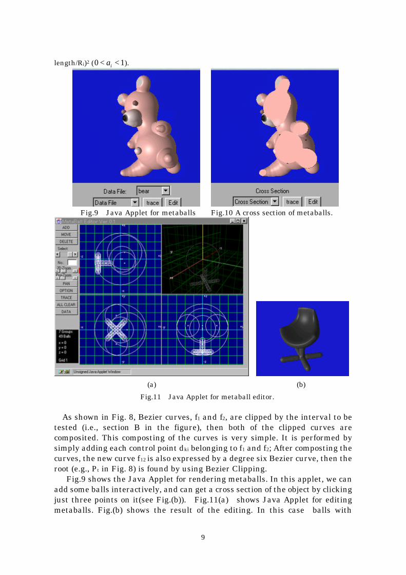
length/Ri)2 (0 1< <ai ).
Fig.9 Java Applet for metaballs Fig.10 A cross section of metaballs.
(a) (b)
Fig.11 Java Applet for metaball editor.
As shown in Fig. 8, Bezier curves, f1 and f2, are clipped by the interval to betested (i.e., section B in the figure), then both of the clipped curves arecomposited. This composting of the curves is very simple. It is performed bysimply adding each control point dki belonging to f1 and f2; After composting thecurves, the new curve f12 is also expressed by a degree six Bezier curve, then theroot (e.g., Pt in Fig. 8) is found by using Bezier Clipping. Fig.9 shows the Java Applet for rendering metaballs. In this applet, we canadd some balls interactively, and can get a cross section of the object by clickingjust three points on it(see Fig.(b)). Fig.11(a) shows Java Applet for editingmetaballs. Fig.(b) shows the result of the editing. In this case balls with

10
negative density are used to obtain holes. Fig. 12 (a) shows killer whales modeled by metaballs. This is one frame
from a HDTV size animation. This figure shows the optical effects in watersuch as caustics on the whales and shafts of light[Nishi94b]. Fig. 13(a)-(b) show examples of two types of free-form surfaces in the scene.Fig. 13(a) shows Bezier surfaces (car and tree) and metaballs (clouds and afrog). Both types of surfaces can be displayed by a single program. Themetaball technique is also useful for displaying translucent objects such asclouds/smoke. Clouds are defined by density fields, which are modeled by themetaball technique. That is, the surface of a cloud is defined by the isosurfacesof potential fields defined by the metaballs. Multiple scattering is taken intoaccount for the clouds[Nishi96a]. The intersections of the isosurface (i.e., cloudsurface) with the viewing ray are calculated by raytracing based on Bezierclipping. Fig.(b) shows teapot with water droplets; the teapot is modeled by32 Bezier patches, and water droplets are defined by metaballs.
Fig.12 Examples of metaballs with optical effects within water.
(a) (b)
Fig.13 Examples of raytraced scenes containing Bezier patches and metaballs
5. Displaying Metacircles
11
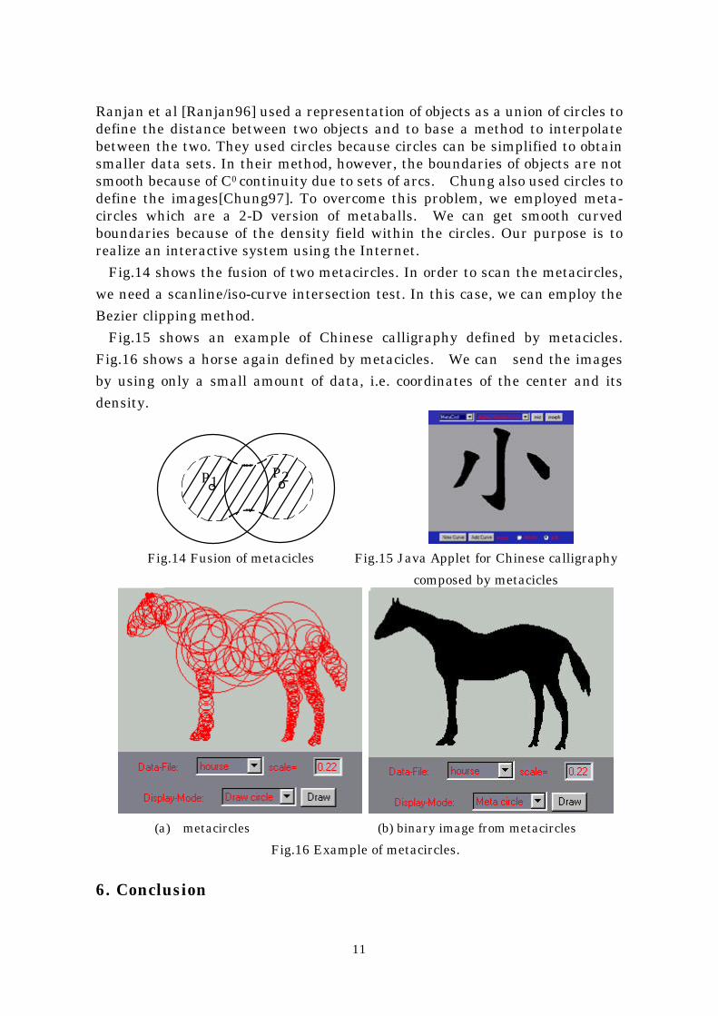
Ranjan et al [Ranjan96] used a representation of objects as a union of circles todefine the distance between two objects and to base a method to interpolatebetween the two. They used circles because circles can be simplified to obtainsmaller data sets. In their method, however, the boundaries of objects are notsmooth because of C0 continuity due to sets of arcs. Chung also used circles todefine the images[Chung97]. To overcome this problem, we employed meta-circles which are a 2-D version of metaballs. We can get smooth curvedboundaries because of the density field within the circles. Our purpose is torealize an interactive system using the Internet.
Fig.14 shows the fusion of two metacircles. In order to scan the metacircles,we need a scanline/iso-curve intersection test. In this case, we can employ theBezier clipping method.
Fig.15 shows an example of Chinese calligraphy defined by metacicles.Fig.16 shows a horse again defined by metacicles. We can send the imagesby using only a small amount of data, i.e. coordinates of the center and itsdensity.
P1 P2
Fig.14 Fusion of metacicles Fig.15 Java Applet for Chinese calligraphy
composed by metacicles
(a) metacircles (b) binary image from metacircles
Fig.16 Example of metacircles.
6. Conclusion
12
We have introduced a display system for Bezier surfaces and metaballs usingBezier Clipping. The Bezier Clipping is a very powerful solver for geometricmodeling and shading models. As shown in the examples, the systemdescribed here gives us photo-realistic images. The advantages of the methods described here are as follows: (1) Both of parametric and implicit surface can be displayed with highaccuracy (i.e., without polygonization). (2) Various shading effects for parametric surfaces can be simulated:cylindrical/curved light sources, radiosity. (3) In the systems, parametric patches and metaballs can be displayed by asingle program. (4) Because of the effectiveness of Bezier clipping, we can develop aninteractive system through the Internet.
Please refer the following URL for interactive applications of Bezier clipping.http://www.eml.hiroshima-u.ac.jp/~nis/javaexampl/demoEng.html
AcknowledgmentI would like to acknowledge Prof. Sederberg of Brigham Young University forhis contribution to our discussion on Bezier clipping.
References[Blinn80] J.F.Blinn, “A Generalization of Algebraic Surface Drawing," ACM
Transaction on Graphics, Vol.2, No.3 (1980) pp.235-256.[Chung 97] J.Chung, N.Ohnishi, “Chain of Circles for Matcing and Recognition of
Planer Shapes,” IDY97-52,1997, pp.23-30.[Fournier94] A. Fournier, J.Buchanan, “Chebyshev Polynomials for Boxing and
Intersections of Parametric Curves and Surfaces,” Proc. ofEUROGRAPHICS’94 (1994) pp.127-142.
[Kajiya82] Kajiya, J., “Ray Tracing Parametric Patches,“ Computer Graphics, Vol.16,No.3 (1982) pp.245-254.
[Kaneda96] K.Kaneda, Y.Zuyama, H.Yamashita, T.Nishita, “Animation of WaterDroplet Flow on Curved Surfaces,'' Proc. of Pacific’96 (1996)
[Kim95] J.Kim, D.Park, “Efficient Ray Tracing Trimmed Rational SurfacePatches,” Proc. of Pacific Grapphics’95 (1995) pp.209-221.
[Lane80] J.Lane, L.Carpenter, T.Whitted, “Scan line Methods for DisplayingParametrically Defined Surfaces," CACM, Vol. 23, No.1 (1980) pp.23-34.
[Nishim85] H. Nishimura, M.Hirai, T.Kawai, T.Kawata, I.Shirakawa, K.Omura,“Object Modeling by Distribution Function and a Method of Imagegeneration,'', Journal of papers given by at the ElectronicsCommunication Conference'85 J68-D(4) pp.718-725 (in Japanese).
[Nishi90] T.Nishita, T.W.Sederberg, M.Kakimoto, “Ray Tracing Rational TrimmedSurface Patches,'' Computer Graphics, Vol.24, No.4 (1990), pp.337-345.
[Nishi91a] T.Nishita, K.Kaneda, E.Nakamae, “A Scanline Algorithm for DisplayingTrimmed Surfaces by using Bezier Clipping," The Visual Computer, Vol.7,No.5 (1991) pp.269-258.
[Nishi91b] T.Nishita, S.Takita, E.Nakamae, “Scan Conversion of Regions Bounded by
13
Bezier Curves," Proc. of CG & CAD (1991) pp.198-204.[Nishi92a] T.Nishita, S.Takita, E.Nakamae, “Shading Model of Parallel Cylindrical
Light Sources," CG International'92 (1992) pp.429-445.[Nishi92b] T.Nishita, S.Takita, E.Nakamae, “Hidden Curve Elimination of Trimmed
Surfaces Using Bezier Clipping," CG International'92 (1992) pp.595-619.[Nishi93a] T.Nishita, S.Takita, E.Nakamae, “A Display Algorithm of Brush Strokes
using Bezier Functions," CG International'93 (1993) pp.244-257.[Nishi93b] T.Nishita, K.Fujii, E.Nakamae, “Metamorphosis using Bezier Clipping,"
Pacific Graphics'93 (1993) pp.162-173.[Nishi93c] T.Nishita, T. Shirai, K.Tadamura, E. Nakamae, ”Display of The Earth
Taking into Account Atmospheric Scattering,''Proc. of SIGGRAPH'93(1993) pp.175-182.
[Nishi93d] T.Nishita, E.Nakamae, “A New Radiosity Approach Using Area Samplingfor Parametric Patches," Proc. of EUROGRAPHICS'93 pp.385-393.
[Nishi94a] T.Nishita, E.Nakamae, ”A Method for Displaying Metaballs by usingBezier Clipping,'' Proc. of EUROGRAPHICS '94, Vol.13, No.3 (1994) c271-280.
[Nishi94b] T.Nishita, E.Nakamae, “Method of Displaying Optical Effects within Waterusing Accumulation Buffer,'' Proc. of SIGGRAPH'94 (1994) pp.373-379.
[Nishi96] T.Nishita, Y.Dobashi, E.Nakamae, “Display of Clouds Taking into AccountMultiple Anisotropic Scattering and Sky Light,'' Proc. of SIGGRAPH'96(1996)
[Ranjian96] V.Ranjian, A. Fournier, ”Matching and Interpolation of Shapes usingUnions of Circles”, EUROGRAPHICS’96, Vol.15, No.3, 1996, pp.129-142.
[Seder90] T.Sederberg, T.Nishita, “Curve Intersection using Bezier Clipping," CAD,Vol.22, No.9 (1990) pp.337-345.
[Seder91] T.Sederberg, T.Nishita, “Geometric Hermite Approximation of SurfacePatch Intersection Curves," CAGD, Vol.8, No.2 (1991) pp.97-114.
[Watt90] M.Watt, “Light-Water Interaction using Backward Beam Tracing,''Computer Graphics, Vol.24, No.4 (1990) pp.377-376.
[Whitt80] T.Whitted, “An Improved Illumination Model for Shaded Display,” CACM,23, 6 (1980) pp.96-102.
[Wyvil86a] B.Wyvill, C.McPheeters, G.Wyvill, “Data Structure for Soft Objects,'' TheVisual Computer, 2 (1986) pp.227-234.
[Wyvil86b] B.Wyvill, C.McPheeters, G.Wyvill, ”Animating Soft Objects,'' The VisualComputer, 2 (1986) pp.235-242.