Embed Size (px)
Citation preview

SS; Reviewed: SPOC 8/21/2006
Solution & Interoperability Test Lab Application Notes ©2006 Avaya Inc. All Rights Reserved.
Page 1 of 61 NICE_PC3.doc
Avaya Solution & Interoperability Test Lab
Application Notes for NICE Call Recording 8.9 with Avaya Proactive Contact 3.0 - Issue 1.0
Abstract
These Application Notes describe the configuration steps required for NICE Call Recording 8.9 to successfully interoperate with Avaya Proactive Contact 3.0. NICE Call Recording 8.9 delivers enterprise call recording capabilities to optimize call center quality and performance. NICE Call Recording uses the Event Service of Avaya Proactive Contact 3.0 and the Telephony Services API (TSAPI) of Avaya Application Enablement Services (AES) to extract agent and call event information. NICE Call Recording 8.9 uses the Device and Media Control Services of Avaya AES to perform recording. Information in these Application Notes has been obtained through interoperability compliance testing and additional technical discussions. Testing was conducted via the DeveloperConnection Program at the Avaya Solution and Interoperability Test Lab.

SS; Reviewed: SPOC 8/21/2006
Solution & Interoperability Test Lab Application Notes ©2006 Avaya Inc. All Rights Reserved.
Page 2 of 61 NICE_PC3.doc
1. Introduction These Application Notes describe the compliance-tested configuration utilizing Avaya Proactive Contact 3.0 (PC3) and NICE Call Recording 8.9. NICE Call Recording 8.9 monitors, records, stores and plays back phone calls for verification and quality assurance. NICE Call Recording 8.9 consists of the NiceLog server and the NiceCLS server. The NiceLog server is a digital voice logging system. NiceLog records and archives audio from multiple sources. Audio is recorded to the hard drive of the NiceLog server for immediate playback capability. The NiceCLS contains the CMAPI connector, TSAPI connector and PC3 connector. These connectors allow NICE Call Recording 8.9 to receive and monitor agent and call events from Avaya Communication Manager and Avaya Proactive Contact 3.0. NiceCLS uses the Event Service of Avaya Proactive Contact 3.0 and the Telephony Services API (TSAPI) of Avaya Application Enablement Services (AES) to receive events concerning particular stations, agents, and agent ACD/skill groups. NICE uses these events as recording triggers. There are many methods that NICE Call Recording 8.9 can use for call recording. During the compliance testing, the Device and Media Control Services1 of Avaya AES were used for call recording. The NiceCLS uses the Device and Media Control Services of AES to register AES Devices and Media Control API “virtual” stations with Avaya Communication Manager. The AES Device and Medial Control API stations essentially appear as IP softphones to Avaya Communication Manager. NiceCLS records a call by issuing a Single Step Conference (SSC) request via TSAPI to bridge an AES Device and Media Control API station onto an active call. Since the IP address of the AES Device and Media Control API station is that of the NiceLog server, the audio portion of the call is directed to the NiceLog server and can thus be recorded. There are three possible system deployments of Avaya Proactive Contact 3.0.
• Avaya Proactive Contact with computer telephony interface (CTI) • Avaya Proactive Contact with Avaya Proactive Contact Gateway PG230 • Avaya Proactive Contact with the System Cabinet (the System Cabinet contains the
PG230)
The compliance testing was configured with Avaya Proactive Contact with the System Cabinet.
1.1. Integration Overview Figure 1 depicts an overview of the NICE Call Recording 8.9 integration to Avaya Proactive Contact 3.0. The configuration consists of a pair of redundant Avaya S8700 Media Servers, an Avaya MCC1 Media Gateway, an Avaya AES server, Avaya IP Telephones, an Avaya Proactive Contact System Cabinet, agent workstations, and NICE servers (NiceCLS and NiceLog servers).
1 Formally known as Communication Manager Application Programming Interface, or CMAPI.

SS; Reviewed: SPOC 8/21/2006
Solution & Interoperability Test Lab Application Notes ©2006 Avaya Inc. All Rights Reserved.
Page 3 of 61 NICE_PC3.doc
There is one TSAPI CTI link configured between Avaya Communication Manager and AES in this test environment. This CTI link is used jointly by PC3 and NiceCLS as TSAPI CTI users. The NiceLog server contains two network interfaces. The first network interface is used as the NiceLog server’s TCP/IP network connection for control and playback purposes, and the second network interface is used for audio.
Figure 1: Avaya Proactive Contact 3.0 and NICE Call Recording 8.9 Integration

SS; Reviewed: SPOC 8/21/2006
Solution & Interoperability Test Lab Application Notes ©2006 Avaya Inc. All Rights Reserved.
Page 4 of 61 NICE_PC3.doc
2. Equipment and Software Validated The following equipment and software were used for the test configuration provided:
Equipment Software Avaya Proactive Contact System Cabinet with B2600 HP Server and Digital PG230 Switch
Proactive Contact 3.0 Build 36
Avaya S8700 Media Servers Avaya Communication Manager 3.1.2 (R013x.01.2.632.1)
Avaya MCC1 Media Gateway TN2312BP IP Server Interface HW03 FW031 TN799DP C-LAN Interface HW01 FW017 TN2302AP IP Media Processor HW13 FW111 Avaya 4610SW IP Telephones (H.323) 2.1.3 Avaya Application Enablement Services 3.1.1 Patch 1, Build 43.2 Avaya C363T-PWR Converged Stackable Switch 4.5.14 Avaya C364T-PWR Converged Stackable Switch 4.5.14 NiceCLS Windows 2003 SP1Server Version 8.9 NiceLog Windows 2003 SP1 Server Version 8.9
3. Configure Avaya Communication Manager This section provides the procedures for configuring Avaya Communication Manager. The following items will be configured:
• Computer Telephony Integration (CTI) Link • Recording Ports • Codec Set • IP Network Regions
The Avaya Communication Manager to Avaya Proactive Contact configuration is outside the scope of these Application Notes and should already be operating successfully.
3.1. Configure the Computer Telephony Integration Link The following steps demonstrate the configuration of the Avaya Communication Manager side of the AES and CTI links.

SS; Reviewed: SPOC 8/21/2006
Solution & Interoperability Test Lab Application Notes ©2006 Avaya Inc. All Rights Reserved.
Page 5 of 61 NICE_PC3.doc
Step Description
1. Enter the display system-parameters customer-options command. On Page 3 of the system-parameters customer-options form, verify that Computer Telephony Adjunct Links is set to “y”. If not, contact an authorized Avaya account representative to obtain the license. display system-parameters customer-options Page 3 of 11 OPTIONAL FEATURES Abbreviated Dialing Enhanced List? y Audible Message Waiting? y Access Security Gateway (ASG)? n Authorization Codes? y Analog Trunk Incoming Call ID? y Backup Cluster Automatic Takeover? n A/D Grp/Sys List Dialing Start at 01? y CAS Branch? nAnswer Supervision by Call Classifier? y CAS Main? n ARS? y Change COR by FAC? n ARS/AAR Partitioning? y Computer Telephony Adjunct Links? y ARS/AAR Dialing without FAC? y Cvg Of Calls Redirected Off-net? y ASAI Link Core Capabilities? y DCS (Basic)? y ASAI Link Plus Capabilities? y DCS Call Coverage? y Async. Transfer Mode (ATM) PNC? n DCS with Rerouting? y Async. Transfer Mode (ATM) Trunking? y ATM WAN Spare Processor? n Digital Loss Plan Modification? n ATMS? y DS1 MSP? n Attendant Vectoring? n DS1 Echo Cancellation? n
2. Enter the display node-names ip command. Note the IP address of the AES server. Note the node names and IP addresses of the C-LAN boards. In the compliance-tested configuration, one C-LAN board (clan-1b04) was used for connectivity to AES (It is assumed that the C-LAN board has already been administered). display node-names ip Page 1 of 1 IP NODE NAMES Name IP Address Name IP Address abacus-5000 192.45 .100.201 . . . aes98 192.45 .95 .98 . . . cceserver 192.45 .120.15 . . . clan-1a03 192.45 .100.97 . . . clan-1b04 192.45 .100.84 . . . clan-1b09 192.45 .100.87 . . . clanP2-1a04 192.168.61 .21 . . . clanP27-2a03 172.16 .252.200 . . . clanP7-3a04 192.168.1 .10 . . . default 0 .0 .0 .0 . . . devcon32-1a03 192.45 .100.36 . . . devcon33-1a03 192.45 .100.16 . . . ipoffice-room3 192.45 .30 .162 . . . medpro-1b05 192.45 .100.85 . . . procr 192.45 .100.81 . . . prowlerP2-1a05 192.168.61 .22 . . .

SS; Reviewed: SPOC 8/21/2006
Solution & Interoperability Test Lab Application Notes ©2006 Avaya Inc. All Rights Reserved.
Page 6 of 61 NICE_PC3.doc
Step Description 3. Enter the change ip-services command. On Page 1 of the IP SERVICES form,
configure entries for the C-LAN board for the AES link as follows: • Service Type – set to “AESVCS”. • Enabled – set to “y”. • Local Node – set to the node name of a C-LAN (“clan-1b04” in the example). • Local Port – set to “8765”.
change ip-services Page 1 of 3 IP SERVICES Service Enabled Local Local Remote Remote Type Node Port Node Port SAT y clanP27-2a03 5023 any 0 SAT y clan-1b04 5023 any 0 AESVCS y clan-1b04 8765 AESVCS y clan-1b09 8765
4. On Page 3, enter the hostname of the AES server for AE Services Server and an alphanumeric password for Password. Set Enabled to “y”. The same password will be configured on the AES server in Section 4.2 Step 4. change ip-services Page 3 of 3 AE Services Administration Server ID AE Services Password Enabled Status Server 1: devconaes01 * y 2: AES-DevCon2 * y in use 3: 4: 5:
5. Enter the add cti-link m command, where m is an available number between 1 and 16, inclusive. Enter an Extension, a valid number under the provisioned dial plan in Avaya Communication Manager. Set Type to “ADJ-IP”, and assign a descriptive Name to the CTI link. add cti-link 15 Page 1 of 2 CTI LINK CTI Link: 15 Extension: 24998 Type: ADJ-IP COR: 1 Name: AES DEVCON2715

SS; Reviewed: SPOC 8/21/2006
Solution & Interoperability Test Lab Application Notes ©2006 Avaya Inc. All Rights Reserved.
Page 7 of 61 NICE_PC3.doc
3.2. Recording Ports The recording ports in this configuration are AES Device and Media Control API stations that essentially appear as IP softphones to Avaya Communication Manager. Each AES Device and Media Control API station requires an “IP_API_A” license. Note that this is separate and independent of Avaya IP Softphone licenses, which are required for Avaya IP Softphones but not required for AES Device and Media Control API stations. Step Description
1. Enter the display system-parameters customer-options command and verify that there are sufficient IP_API_A licenses. If not, contact an authorized Avaya account representative to obtain these licenses display system-parameters customer-options Page 10 of 11 MAXIMUM IP REGISTRATIONS BY PRODUCT ID Product ID Rel. Limit Used IP_API_A : 100 4 IP_API_B : 100 0 IP_API_C : 100 0 IP_Agent : 300 0 IP_IR_A : 0 0 IP_Phone : 12000 4 IP_ROMax : 12000 0 IP_Soft : 300 0 IP_eCons : 0 0

SS; Reviewed: SPOC 8/21/2006
Solution & Interoperability Test Lab Application Notes ©2006 Avaya Inc. All Rights Reserved.
Page 8 of 61 NICE_PC3.doc
Step Description 2. Enter the add station s command, where s is an extension valid under the provisioned dial
plan. On Page 1 of the STATION form, set Type to an IP (IP telephone set type was used for this configuration) or digital telephone set type, set Port to “IP” and enter a descriptive Name. Specify the Security Code, and set IP SoftPhone to “y”. Repeat this as necessary, with the same Security Code2, to configure additional AES Device and Media Control API stations. For the compliance testing, station extensions 23301 through 23304 were configured. change station 23301 Page 1 of 5 STATION Extension: 23301 Lock Messages? n BCC: 0 Type: 4624 Security Code: 12345 TN: 1 Port: IP Coverage Path 1: COR: 1 Name: CMAPI Recording line 1 Coverage Path 2: COS: 1 Hunt-to Station: STATION OPTIONS Loss Group: 19 Personalized Ringing Pattern: 1 Message Lamp Ext: 23301 Speakerphone: 2-way Mute Button Enabled? y Display Language: english Survivable GK Node Name: Survivable COR: internal Media Complex Ext: Survivable Trunk Dest? y IP SoftPhone? y IP Video Softphone? n
3.3. Codec Configuration Step Description
1. Enter the change ip-codec-set t command, where t is a number between 1 and 7, inclusive. Enter a codec for Audio Codec. “G.711MU” was used during compliance testing. change ip-codec-set 1 Page 1 of 2 IP Codec Set Codec Set: 1 Audio Silence Frames Packet Codec Suppression Per Pkt Size(ms) 1: G.711MU n 3 30 2: G.711A n 3 30 3: 4:
2 The NICE application requires the Security Code to be the same for all the AES Device and Media Control API stations.

SS; Reviewed: SPOC 8/21/2006
Solution & Interoperability Test Lab Application Notes ©2006 Avaya Inc. All Rights Reserved.
Page 9 of 61 NICE_PC3.doc
3.4. IP Network Regions During compliance testing, the IP telephones, IP Softphones, AES Device and Media Control API stations, and Media Processors (MedPro) boards were assigned to a common IP network region3. Therefore the RTP traffic between them was governed by the same codec set. Other configurations where multiple IP network regions are utilized are possible, as long as careful consideration is given to the assignment of codec sets between IP network regions. Step Description
1. Enter the change ip-network-region u command, where u the number of the common IP network region discussed above. Set Codec Set to the ip-codec-set number configured in Section 3.3. change ip-network-region 7 Page 1 of 19 IP NETWORK REGION Region: 7 Location: Authoritative Domain: Name: MEDIA PARAMETERS Intra-region IP-IP Direct Audio: yes Codec Set: 1 Inter-region IP-IP Direct Audio: yes UDP Port Min: 2048 IP Audio Hairpinning? n UDP Port Max: 3327 DIFFSERV/TOS PARAMETERS RTCP Reporting Enabled? y Call Control PHB Value: 46 RTCP MONITOR SERVER PARAMETERS Audio PHB Value: 46 Use Default Server Parameters? y Video PHB Value: 26 802.1P/Q PARAMETERS Call Control 802.1p Priority: 6 Audio 802.1p Priority: 6 Video 802.1p Priority: 5 AUDIO RESOURCE RESERVATION PARAMETERS H.323 IP ENDPOINTS RSVP Enabled? n H.323 Link Bounce Recovery? y Idle Traffic Interval (sec): 20 Keep-Alive Interval (sec): 5
3.5. Trunks to Avaya Proactive Contact System Cabinet Avaya Communication Manager has tie trunks configured to the Avaya Proactive Contact 3.0 System Cabinet. Some of these tie trunks are used specifically to set up a dedicated connection between PC3 and Avaya Communication Manager when the agent logs in. This connection stays up during the entire length of time the agent is logged in to PC3. The tie trunk group used for the dedicated connection needs to be known by the NiceCLS server, so that calls are not recorded on these trunks.
3 The assignment of IP network regions on C-LAN and MedPro boards is configured using the change ip-interface SAT command.

SS; Reviewed: SPOC 8/21/2006
Solution & Interoperability Test Lab Application Notes ©2006 Avaya Inc. All Rights Reserved.
Page 10 of 61 NICE_PC3.doc
Step Description 1. Enter the display trunk group 170 command to view the trunk group used when the agent
logs in to PC3. Trunk group 170 is used for this compliance testing. display trunk-group 170 Page 1 of 22 TRUNK GROUP Group Number: 170 Group Type: tie CDR Reports: y Group Name: PDS S1-21-1 01-18 HS COR: 1 TN: 1 TAC: 1170 Direction: two-way Outgoing Display? n Trunk Signaling Type: Dial Access? y Busy Threshold: 255 Night Service: Queue Length: 0 Incoming Destination: Comm Type: voice Auth Code? n Trunk Flash? n Trunk Type (in/out): wink/wink
4. Configure Avaya Application Enablement Services This section assumes that installation and basic administration of an Avaya Application Enablement Services server has been performed. The steps in this section describe the configuration of a TSAPI CTI user for NICE, a “Switch Connection” to Avaya Communication Manager, a TSAPI CTI Link, and CMAPI IP softphone registrations.
4.1. User Management Step Description
1. Launch a web browser, enter https://<IP address of AES server>:8443/MVAP in the URL, and log in with the appropriate credentials for accessing the AES User Management pages.
SS; Reviewed: SPOC 8/21/2006
Solution & Interoperability Test Lab Application Notes ©2006 Avaya Inc. All Rights Reserved.
Page 11 of 61 NICE_PC3.doc
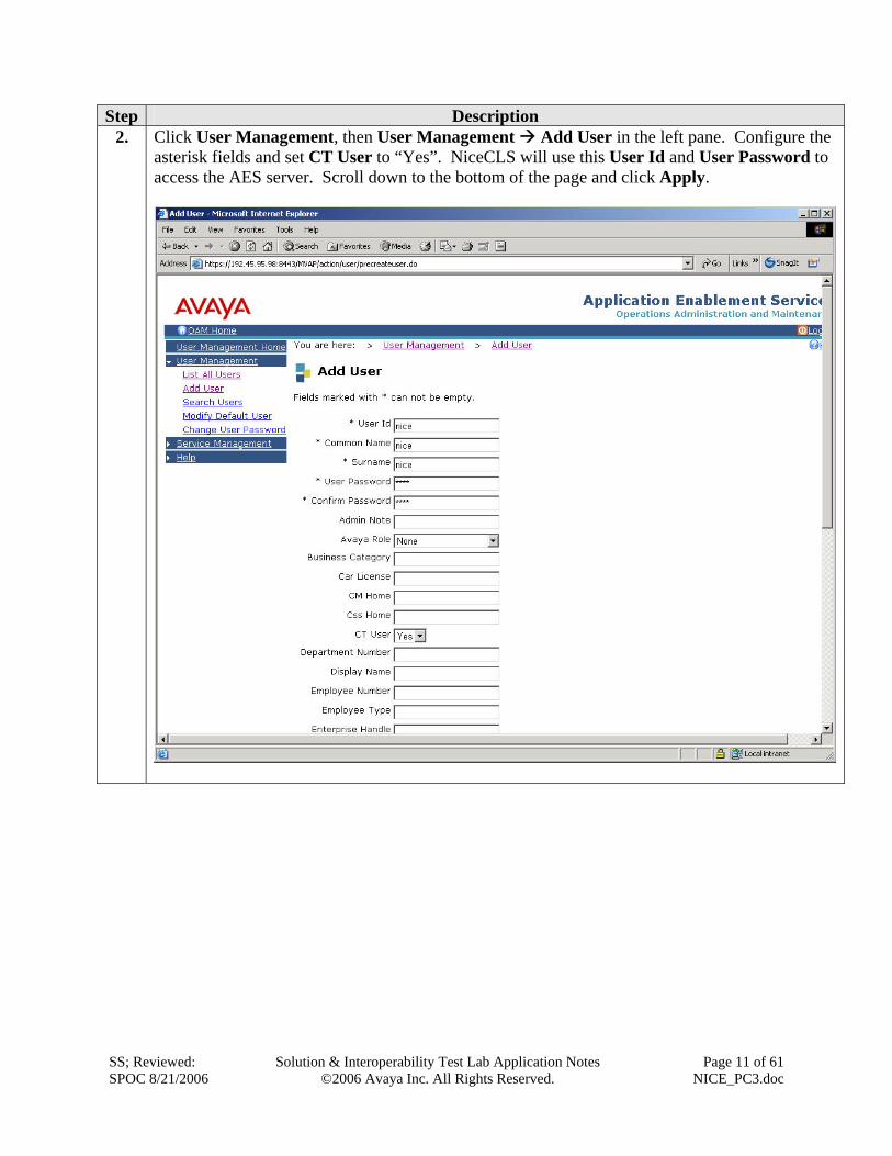
Step Description 2. Click User Management, then User Management Add User in the left pane. Configure the
asterisk fields and set CT User to “Yes”. NiceCLS will use this User Id and User Password to access the AES server. Scroll down to the bottom of the page and click Apply.

SS; Reviewed: SPOC 8/21/2006
Solution & Interoperability Test Lab Application Notes ©2006 Avaya Inc. All Rights Reserved.
Page 12 of 61 NICE_PC3.doc
4.2. CTI OAM Admin Step Description
1. Launch a web browser, enter https://<IP address of AES server>:8443/MVAP in the URL, and log in with the appropriate credentials for accessing the AES CTI OAM pages.
2. Click CTI OAM Home in the left pane to display the Welcome to CTI OAM Screens window. Verify that the Avaya Application Enablement Services is licensed for the TSAPI Service. If the TSAPI Service is not licensed, contact the Avaya sales team or business partner for a proper license file.

SS; Reviewed: SPOC 8/21/2006
Solution & Interoperability Test Lab Application Notes ©2006 Avaya Inc. All Rights Reserved.
Page 13 of 61 NICE_PC3.doc
Step Description 3. Click CTI OAM Home Administration Switch Connections in the left pane to display
the Switch Connections page. A switch connection defines a connection between the AES server and Avaya Communication Manager. Enter a descriptive name for the Switch Connection and click Add Connection.

SS; Reviewed: SPOC 8/21/2006
Solution & Interoperability Test Lab Application Notes ©2006 Avaya Inc. All Rights Reserved.
Page 14 of 61 NICE_PC3.doc
Step Description 4. The next window that appears prompts for the switch connection password. Enter the same
password that was administered on Avaya Communication Manager in Section 3.1 Step 4. Check the SSL checkbox and click Apply.

SS; Reviewed: SPOC 8/21/2006
Solution & Interoperability Test Lab Application Notes ©2006 Avaya Inc. All Rights Reserved.
Page 15 of 61 NICE_PC3.doc
Step Description 5. After returning to the Switch Connections page, select the radio button corresponding to the
switch connection added in Step 3, and click Edit CLAN IPs.

SS; Reviewed: SPOC 8/21/2006
Solution & Interoperability Test Lab Application Notes ©2006 Avaya Inc. All Rights Reserved.
Page 16 of 61 NICE_PC3.doc
Step Description 6. Enter the IP address of a C-LAN board from Section 3.1 Step 2, and click Add Name or IP.
7. Under Administration in the left pane, click CTI Link Admin TSAPI Links. Click Add Link.

SS; Reviewed: SPOC 8/21/2006
Solution & Interoperability Test Lab Application Notes ©2006 Avaya Inc. All Rights Reserved.
Page 17 of 61 NICE_PC3.doc
Step Description 8. Set Switch Connection to the switch connection added in Step 3, and Switch CTI Link
Number to the CTI link number configured on Avaya Communication Manager in Section 3.1 Step 5. The TSAPI Link field is significant to this AES server only and may be set to any unused value. Click Apply Changes.

SS; Reviewed: SPOC 8/21/2006
Solution & Interoperability Test Lab Application Notes ©2006 Avaya Inc. All Rights Reserved.
Page 18 of 61 NICE_PC3.doc
Step Description 9. Click Apply to confirm the changes.

SS; Reviewed: SPOC 8/21/2006
Solution & Interoperability Test Lab Application Notes ©2006 Avaya Inc. All Rights Reserved.
Page 19 of 61 NICE_PC3.doc
Step Description 10. Under Maintenance in the left pane, click Service Controller. Check the TSAPI Service
checkbox and click Restart Service.
11. Click Restart to confirm the restart.

SS; Reviewed: SPOC 8/21/2006
Solution & Interoperability Test Lab Application Notes ©2006 Avaya Inc. All Rights Reserved.
Page 20 of 61 NICE_PC3.doc
Step Description 12. In the left panel of the CTI OAM Home, click Security Database Tlinks to view the Tlink
names (these names are automatically generated by AES). The Tlink Name that includes the switch connection created in Step 3 will be used by the NiceCLS server.

SS; Reviewed: SPOC 8/21/2006
Solution & Interoperability Test Lab Application Notes ©2006 Avaya Inc. All Rights Reserved.
Page 21 of 61 NICE_PC3.doc
Step Description 13. Under Administration in the left pane, click Switch Connections. Select the radio button
corresponding to the switch connection added in Step 3, and click Edit H.323 Gatekeeper. Steps 13 and 14 are needed for CMAPI administration only if the C-LAN board used for CMAPI is different then the board administered in Step 6. (The compliance test used the same C-LAN board and these steps are shown for reference purposes.)
14. Enter the IP address of a C-LAN board from Section 3.1 Step 2, and click Add Name or IP. (The compliance test configuration used the same CLAN board from Step 6 for the H.323 Gatekeeper.)

SS; Reviewed: SPOC 8/21/2006
Solution & Interoperability Test Lab Application Notes ©2006 Avaya Inc. All Rights Reserved.
Page 22 of 61 NICE_PC3.doc
Step Description 15. Under Maintenance in the left pane, click Service Controller. Check the CMAPI Service
checkbox and click Restart Service.

SS; Reviewed: SPOC 8/21/2006
Solution & Interoperability Test Lab Application Notes ©2006 Avaya Inc. All Rights Reserved.
Page 23 of 61 NICE_PC3.doc
Step Description 16. Under Administration in the left pane, click Security Database Devices to add new Avaya
Communication Manager devices (e.g. Phone, VDN, Hunt Group). Enter the Device ID and click Add Device. For the compliance testing, the PC3 agent telephone extensions, CMAPI recording extensions, PC3 VDNs and the hunt groups used for PC3 Agent Predictive Blending were added.

SS; Reviewed: SPOC 8/21/2006
Solution & Interoperability Test Lab Application Notes ©2006 Avaya Inc. All Rights Reserved.
Page 24 of 61 NICE_PC3.doc
Step Description 17. The Add/Edit Device window appears. Select the Device Type and click Apply Changes to
finish adding the new device. Click Apply when the Apply Changes to Device Properties window appears.
18. Repeat Steps 16-17 to add additional Phones, VDNs, and Hunt Group Extensions associated with PC3.
SS; Reviewed: SPOC 8/21/2006
Solution & Interoperability Test Lab Application Notes ©2006 Avaya Inc. All Rights Reserved.
Page 25 of 61 NICE_PC3.doc
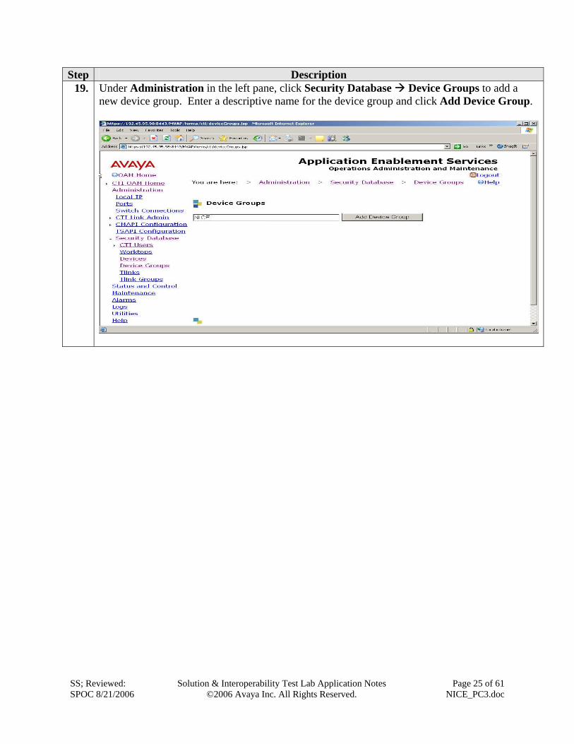
Step Description 19. Under Administration in the left pane, click Security Database Device Groups to add a
new device group. Enter a descriptive name for the device group and click Add Device Group.

SS; Reviewed: SPOC 8/21/2006
Solution & Interoperability Test Lab Application Notes ©2006 Avaya Inc. All Rights Reserved.
Page 26 of 61 NICE_PC3.doc
Step Description 20. The Add / Edit Device Group window appears. Select the Devices associated with PC3 and
click Apply Changes. Click Apply when the Apply Changes to Device Group Properties window appears.

SS; Reviewed: SPOC 8/21/2006
Solution & Interoperability Test Lab Application Notes ©2006 Avaya Inc. All Rights Reserved.
Page 27 of 61 NICE_PC3.doc
Step Description 21. Under Administration in the left pane, click Security Database CTI Users List All
Users. Select the User ID created in Section 4.1 Step 2 and click Edit.

SS; Reviewed: SPOC 8/21/2006
Solution & Interoperability Test Lab Application Notes ©2006 Avaya Inc. All Rights Reserved.
Page 28 of 61 NICE_PC3.doc
Step Description 22. The Edit CTI User window appears. Select the device group created in Step 19 for Call
Origination and Termination, Device / Device, and Call / Device. Click Apply Changes. Click Apply when the Apply Changes to User window appears.
5. Configure Avaya Proactive Contact 3.0 These Application Notes assume that the interface with Avaya Proactive Contact 3.0, Avaya S8700 Media Server and Avaya Application Enablement Services has been configured and is operational, and that a calling list has been successfully downloaded to PC3. The following features should have already been configured on PC3.
• Predictive Agent Blending • Intelligent Call Blending
.

SS; Reviewed: SPOC 8/21/2006
Solution & Interoperability Test Lab Application Notes ©2006 Avaya Inc. All Rights Reserved.
Page 29 of 61 NICE_PC3.doc
6. Configure NICE Call Recording 8.9 These Application Notes assume the NiceCLS and NiceLog software has been installed successfully. The following steps will be performed on the NiceCLS server:
• Configure CTI Drivers • Map the Virtual Extensions in the Logger Definition Tool • Configure the Site in NICE Administrator
6.1. Configure CTI Drivers The following drivers need to be configured on the NiceCLS server:
• CMAPI Driver • TSAPI Driver • PC3 Driver
6.1.1. Configure CMAPI Driver
Step Description 1. On the NiceCLS server, select Start Programs NiceCLS Server 8.9
NiceCLS Server Controller. In the NiceCLS Server Controller window, select Switch Driver Setup CMAPI – Site Configuration… to configure the CMAPI driver.

SS; Reviewed: SPOC 8/21/2006
Solution & Interoperability Test Lab Application Notes ©2006 Avaya Inc. All Rights Reserved.
Page 30 of 61 NICE_PC3.doc
Step Description 2. The NICE CMAPI Configuration Utility window will appear. Click Switches on
the left pane, and then click New.
In the New Switch Properties window, configure the following.
• Switch Name – set to “NICE” or any unique name. • CLAN Board IP Address – set to the IP address of the CLAN board
configured in Section 4.2 Step 14. • Switch ID – set to “1” or any unique id. • Default Virtual Station Password – set to the station’s security code
configured in Section 3.2. • Codec – select “g711U”, as configured in Section 3.4, from the drop down
list.
Click OK.

SS; Reviewed: SPOC 8/21/2006
Solution & Interoperability Test Lab Application Notes ©2006 Avaya Inc. All Rights Reserved.
Page 31 of 61 NICE_PC3.doc
Step Description 3. Click CMAPI on the left pane, and click New.
In the New CMAPI Properties window, configure the following.
• Name – set to “NICECMAPI” or any unique name. • ID – set to the same Switch ID from Step 2. • Related Switch – use the drop down list to select the switch created in Step 2. • IP Address – set to the IP address of the AES server shown in Section 3.1
Step 2. • Port – set to “4721”.
Click OK.

SS; Reviewed: SPOC 8/21/2006
Solution & Interoperability Test Lab Application Notes ©2006 Avaya Inc. All Rights Reserved.
Page 32 of 61 NICE_PC3.doc
Step Description 4. Click Proxies on the left pane, and click New.
In the New Proxy Properties window, configure the following.
• Name – set to “NICEPROXY” or any unique name. • Address – set to “Localhost” or the IP address of the NiceCLS server. • Port – set to “1327”. • Related CMAPI – use the drop down list to select the CMAPI created in Step
3. • Proxy ID – set to the ID configured in Step 2. • User Name – set to any unique user name. • Password – set to valid password string.
Click OK.

SS; Reviewed: SPOC 8/21/2006
Solution & Interoperability Test Lab Application Notes ©2006 Avaya Inc. All Rights Reserved.
Page 33 of 61 NICE_PC3.doc
Step Description 5. From the NICE CMAPI Configuration Utility window, click the Save icon on the
top right.
6.1.2. Configure TSAPI Driver
Step Description 1. On the NiceCLS server, select Start Programs NiceCLS Server 8.9
NiceCLS Server Controller. In the NiceCLS Server Controller window, select Switch Driver Setup Avaya-Definity G3 – Passageway… to configure the TSAPI driver.

SS; Reviewed: SPOC 8/21/2006
Solution & Interoperability Test Lab Application Notes ©2006 Avaya Inc. All Rights Reserved.
Page 34 of 61 NICE_PC3.doc
Step Description 2. The Generic CTI Driver Setup window will appear. Select “1-LucentTS” from the
drop down list for Driver to be Configured. Keep the default value for the SwitchID. Click Next.
3. On the Generic CTI Driver Features configuration, check the checkboxes for Rejected Devices and Advanced Driver Features. Click Next.

SS; Reviewed: SPOC 8/21/2006
Solution & Interoperability Test Lab Application Notes ©2006 Avaya Inc. All Rights Reserved.
Page 35 of 61 NICE_PC3.doc
Step Description 4. Leave all fields blank for the Monitored Devices configuration. Click Next.
5. Leave all fields blank for the Devices Mapping configuration. Click Next.

SS; Reviewed: SPOC 8/21/2006
Solution & Interoperability Test Lab Application Notes ©2006 Avaya Inc. All Rights Reserved.
Page 36 of 61 NICE_PC3.doc
Step Description 6. In the Rejected Devices fields, type the rejected devices using the format TXX#YY,
which corresponds to the following values: T = Trunk XX = Trunk group number YY = Trunk member number (time slot) or “*” for all trunk members For this compliance test, set the Rejected Devices to “T170#*”. Trunk group 170 on Avaya Communication Manager, as described in Section 3.6, is used when the agents log in to PC3. This configuration will reject any calls on trunk group 170. NICE does not want to record the calls that are created when agents log in to PC3.

SS; Reviewed: SPOC 8/21/2006
Solution & Interoperability Test Lab Application Notes ©2006 Avaya Inc. All Rights Reserved.
Page 37 of 61 NICE_PC3.doc
Step Description 7. On the Advanced Driver Features configuration, check the box for Driver works
with a Predictive Dialer driver. Click Finish.
8. The AVAYA Quick Setup - Welcome window will appear. Select “LucentTS” from the drop down list. Click Next.
SS; Reviewed: SPOC 8/21/2006
Solution & Interoperability Test Lab Application Notes ©2006 Avaya Inc. All Rights Reserved.
Page 38 of 61 NICE_PC3.doc
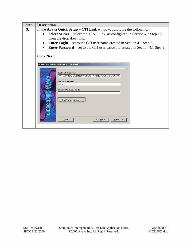
Step Description 9. In the Avaya Quick Setup – CTI Link window, configure the following:
• Select Server – select the TSAPI link, as configured in Section 4.2 Step 12, from the drop down list.
• Enter Login – set to the CTI user name created in Section 4.1 Step 2. • Enter Password – set to the CTI user password created in Section 4.1 Step 2.
Click Next.

SS; Reviewed: SPOC 8/21/2006
Solution & Interoperability Test Lab Application Notes ©2006 Avaya Inc. All Rights Reserved.
Page 39 of 61 NICE_PC3.doc
Step Description 10. In the AVAYA Quick Setup – Recording Method window, set the Recording
Method to “Single Step Conf with DS1’s” from the drop down list. Click Finish.

SS; Reviewed: SPOC 8/21/2006
Solution & Interoperability Test Lab Application Notes ©2006 Avaya Inc. All Rights Reserved.
Page 40 of 61 NICE_PC3.doc
6.1.3. Configure the PC3 Driver
Step Description 1. On the NiceCLS server, select Start Programs NiceCLS Server 8.9
NiceCLS Server Controller. On the NiceCLS Server Controller window, select Switch Driver Setup Avaya - Mosaix Predictive Dialer – CTI … to configure the PC3 Event Services Driver.

SS; Reviewed: SPOC 8/21/2006
Solution & Interoperability Test Lab Application Notes ©2006 Avaya Inc. All Rights Reserved.
Page 41 of 61 NICE_PC3.doc
2. In the General Parameters window, configure the following: • Naming Service Host Name – set to the host name of the PC3 server. • Mosaix Server IP Address – set to the IP address of the PC3 server. • Event Service Object Name – set to the host name of the PC3 server which is
running the Event Service. • Observation – select “Yes” from the drop down list. • Switch Type – select “CentreVu” from the drop down list. • Switch ID – set to “2” or a unique id number.
Click Advanced…

SS; Reviewed: SPOC 8/21/2006
Solution & Interoperability Test Lab Application Notes ©2006 Avaya Inc. All Rights Reserved.
Page 42 of 61 NICE_PC3.doc
3. In the Advanced window, configure the following. • End Call on Agent Off Call – select “No” from the drop down list. • Enable Flush Calls – select “Yes” from the drop down list. • Report Agent ID – select “Yes” from the drop down list.
Click OK.
Click Finish in the General Parameters window.

SS; Reviewed: SPOC 8/21/2006
Solution & Interoperability Test Lab Application Notes ©2006 Avaya Inc. All Rights Reserved.
Page 43 of 61 NICE_PC3.doc
6.2. Configure the Site in NICE Administrator NICE Administrator manages all the NICE machines installed at the site. This section provides the procedures for configuring the NiceCLS server and the NiceLog server.
Step Description 1. On the NiceCLS server, select Start Programs NICE Application NICE
Administrator. The NICE Administrator window appears. Select NiceLog from the New drop down list.

SS; Reviewed: SPOC 8/21/2006
Solution & Interoperability Test Lab Application Notes ©2006 Avaya Inc. All Rights Reserved.
Page 44 of 61 NICE_PC3.doc
Step Description In the General tab, configure the following:
• Name – set to “CMAPI NiceLog” or any unique name. • Network type – select “TCP/IP” from the drop down list. • Network address – set to the IP address of the NiceLog server.
The system connects with the NiceLog server and the information about the server is displayed in the bottom pane. Click the Save icon.

SS; Reviewed: SPOC 8/21/2006
Solution & Interoperability Test Lab Application Notes ©2006 Avaya Inc. All Rights Reserved.
Page 45 of 61 NICE_PC3.doc
Step Description 2. Select CLS Server from the New drop down list.
In the General tab, configure the following:
• Name – set to “CLS Server” or any unique name. • Network type – select “TCP/IP” from the drop down list. • Network address – set to the IP address of the NiceCLS server.

SS; Reviewed: SPOC 8/21/2006
Solution & Interoperability Test Lab Application Notes ©2006 Avaya Inc. All Rights Reserved.
Page 46 of 61 NICE_PC3.doc
Step Description 3. Click the Loggers tab to specify which NiceLog server is connected to the NiceCLS
server. In the Available Loggers list, select CMAPI NiceLog and click to move to the Member Loggers list.
The Members Loggers list should now contain the CMAPI NiceLog entry. Click the Save icon.

SS; Reviewed: SPOC 8/21/2006
Solution & Interoperability Test Lab Application Notes ©2006 Avaya Inc. All Rights Reserved.
Page 47 of 61 NICE_PC3.doc
Step Description 4. Select User from the New drop down list.
This section is used to administer the agent IDs administered on PC3. If the Predictive Agent Blending feature is administered on PC3 for inbound calls, then users must be created with ACD agent IDs also.

SS; Reviewed: SPOC 8/21/2006
Solution & Interoperability Test Lab Application Notes ©2006 Avaya Inc. All Rights Reserved.
Page 48 of 61 NICE_PC3.doc
Step Description 5. In the General tab, configure the following for each PC3 agent:
• First Name – set to a descriptive name for the agent. • Last Name – set to a descriptive name for the agent. • Login name – set to a unique name that the agent can use to log in to the
NICE application. • Password – set to a valid password string that the agent can use to access the
NICE application. • Make user an agent – check the checkbox. • CLS Server – select “CLS Server” from the drop down list. • Agent ID – set to the agent ID corresponding to the PC3 agent. The agent IDs
can be found in the /etc/passwd file on the PC3 server. Note: The agent IDs are automatically generated by PC3 and corresponds to the PC3 agent IDs that the PC3 administrator creates.
• Switch ID – set to the switch ID configured for the PC3 driver in Section
6.1.3 Step 2. Click the Save icon. Repeat Step 5 to create a new user account for additional PC3 agents.

SS; Reviewed: SPOC 8/21/2006
Solution & Interoperability Test Lab Application Notes ©2006 Avaya Inc. All Rights Reserved.
Page 49 of 61 NICE_PC3.doc
Step Description 6. In the General tab, configure the following for each Avaya Communication Manager
ACD agents: • First Name – set to a descriptive name for the agent. • Last Name – set to a descriptive name for the agent. • Login name – set to a unique name that the agent can use to log in to the
NICE application. • Password – set to a valid password string that the agent can use to access the
NICE application. • Make user an agent – check the checkbox. • CLS Server – select “CLS Server” from the drop down list. • Agent ID – set to the agent ID corresponding to the ACD agent ID configured
on Avaya Communication Manager.
Note: These agent IDs need to be administered when Predictive Agent Blending is configured on PC3 for inbound calls.
• Switch ID – set to the switch ID configured for the TSAPI driver in Section 6.1.2 Step 2.
Click the Save icon. Repeat Step 5 to create a new user account for additional ACD agents.

SS; Reviewed: SPOC 8/21/2006
Solution & Interoperability Test Lab Application Notes ©2006 Avaya Inc. All Rights Reserved.
Page 50 of 61 NICE_PC3.doc
6.3. Map the Virtual Extensions in the Logger Definition Tool
Step Description 1. On the NiceCLS server, select Start Programs NiceCLS Server 8.9
NiceCLS Server Controller. On the NiceCLS Server Controller window, select Configuration Logger Definition Tool.

SS; Reviewed: SPOC 8/21/2006
Solution & Interoperability Test Lab Application Notes ©2006 Avaya Inc. All Rights Reserved.
Page 51 of 61 NICE_PC3.doc
Step Description 2. In the Logger Definition Tool window, select Edit Loggers…
3. In the Loggers Configuration window, on the Recording Type column use the drop down list to select “CMAPI SSC”. Click OK.

SS; Reviewed: SPOC 8/21/2006
Solution & Interoperability Test Lab Application Notes ©2006 Avaya Inc. All Rights Reserved.
Page 52 of 61 NICE_PC3.doc
Step Description 4. In the Logger Definition Tool window, use the drop down list on the Recorded
Device Type column to select “Virtual Device”. Configure the Virtual Extension with the extensions of the CMAPI extensions configured on Avaya Communication Manager in Section 3.2. Any of the 192 Channel Numbers can be used.

SS; Reviewed: SPOC 8/21/2006
Solution & Interoperability Test Lab Application Notes ©2006 Avaya Inc. All Rights Reserved.
Page 53 of 61 NICE_PC3.doc
Step Description 5. In the Logger Definition Tool window, select File Build Map File.
In the Logger Mapping window, click OK.

SS; Reviewed: SPOC 8/21/2006
Solution & Interoperability Test Lab Application Notes ©2006 Avaya Inc. All Rights Reserved.
Page 54 of 61 NICE_PC3.doc
7. Interoperability Compliance Testing This interoperability compliance testing covered feature functionality, serviceability and basic load testing. Feature functionality focused on verifying that NICE Call Recording 8.9 could successfully record calls when using events from Avaya Proactive Contact 3.0 and an Avaya AES TSAPI CTI link. Serviceability testing verified that the NiceCLS and NiceLog servers recovered from adverse conditions, such as rebooting, power failure and network disconnect. Basic load testing verified that NICE could successfully record calls for an extended period of time.
7.1. General Test Approach All feature functionality test cases were performed manually to verify proper operation. The general test approach entailed:
• Establishing connectivity between NICE and Avaya AES using TSAPI. • Establishing connectivity between NICE and Avaya Proactive Contact 3.0. • Verifying calls could be recorded using Avaya AES Device and Media Control Services
with Single Step Conference. • Verifying call recording using basic telephony operations such as answer, hold/retrieve,
transfer, consult, conference, and disconnect. • Verifying call recording with outbound and inbound calls. • Verifying call recording with Predictive Agent Blending Feature on PC3. • Verifying call recording with Intelligent Call Blending Feature on PC3.
The basic load testing was automated with outbound calls delivered to agents from Avaya PC3. The Avaya PC3 executed a calling list which delivered answered calls to agents.
7.2. Test Results All feature and performance tests passed. The NICE Call Recording 8.9 successfully recorded, displayed and replayed the recordings of agent. For serviceability testing, NICE was able to resume call recording after restoration of connectivity to the PC3 server, from network disconnect/re-connect, and NICE server resets. For performance testing, NICE successfully recorded calls for a sustained period of time. The following observation was obtained from testing: when using the Intelligent Call Blending feature of PC3, the NICE Query does not show an inbound call as TYPE = INBOUND.
8. Verification Steps
8.1. Avaya Verification The following steps will ensure that the communication between Avaya Communication Manager and Avaya Application Enablement Services server is working.

SS; Reviewed: SPOC 8/21/2006
Solution & Interoperability Test Lab Application Notes ©2006 Avaya Inc. All Rights Reserved.
Page 55 of 61 NICE_PC3.doc
Step Description 1. From the System Access Terminal (SAT) interface on Avaya Communication Manager, verify
that the Service State of the TSAPI link is “established”.
status aesvcs cti-link AE SERVICES CTI LINK STATUS CTI Version Mnt AE Services Service Msgs MsgsLink Busy Server State Sent Rcvd 1 no down 0 0 2 4 no AES-DevCon2 restarted 30 15 3 4 no AES-DevCon2 restarted 30 15 4 4 no AES-DevCon2 established 15 15 15 4 no devconaes01 established 18 18
2. From the AES OAM page, click Status and Control Switch Conn Summary. This summary gives the status of the connection between Avaya Communication Manager and the AES Server. Verify that the Conn State indicates “Talking”.

SS; Reviewed: SPOC 8/21/2006
Solution & Interoperability Test Lab Application Notes ©2006 Avaya Inc. All Rights Reserved.
Page 56 of 61 NICE_PC3.doc
Step Description 3. From the AES OAM page, click Status and Control Services Summary. This summary
gives the status of each service. The TSAPI Service should show the status as “ONLINE”.
SS; Reviewed: SPOC 8/21/2006
Solution & Interoperability Test Lab Application Notes ©2006 Avaya Inc. All Rights Reserved.
Page 57 of 61 NICE_PC3.doc
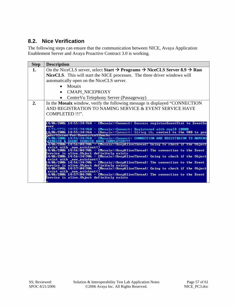
8.2. Nice Verification The following steps can ensure that the communication between NICE, Avaya Application Enablement Server and Avaya Proactive Contract 3.0 is working.
Step Description 1. On the NiceCLS server, select Start Programs NiceCLS Server 8.9 Run
NiceCLS. This will start the NICE processes. The three driver windows will automatically open on the NiceCLS server.
• Mosaix • CMAPI_NICEPROXY • CentreVu Telephony Server (Passageway)
2. In the Mosaix window, verify the following message is displayed “CONNECTION AND REGISTRATION TO NAMING SERVICE & EVENT SERVICE HAVE COMPLETED !!!”.

SS; Reviewed: SPOC 8/21/2006
Solution & Interoperability Test Lab Application Notes ©2006 Avaya Inc. All Rights Reserved.
Page 58 of 61 NICE_PC3.doc
Step Description 3. In the CMAPI_NICEPROXY window, verify the following message is displayed
“Successfully registered station [XXXXX]”. These are the AES Device and Media Control API stations administered in Section 3.2
4. In the CentreVu Telephony Server (Passageway) window, verify the following messages are displayed “Succeeded to monitor XXXX” for all the monitored devices configured on AES.

SS; Reviewed: SPOC 8/21/2006
Solution & Interoperability Test Lab Application Notes ©2006 Avaya Inc. All Rights Reserved.
Page 59 of 61 NICE_PC3.doc
8.3. Replaying the Voice Recordings
Step Description 1. On the NiceCLS server, select Start Programs NICE Applications NICE
Monitor. The NICE Monitor window will open. Double click the agent row to hear the recording. Verify recording can be heard from the speakers on the server.
9. Support If technical support is required for the NICE Call Recording 8.9 solution, then contact NICE Technical Support. Full details are available at https://www.extranice.com.
10. Conclusion These Application Notes describe the required configuration steps for NICE Call Recording 8.9 to successfully interoperate with the Event Service of Avaya Proactive Contact 3.0 for outbound and inbound call recording. NICE used the TSAPI and Device and Media Control Services of Avaya AES to perform the recording. Functionality and performance were successfully validated. The configuration described in these Application Notes has been successfully compliance tested.

SS; Reviewed: SPOC 8/21/2006
Solution & Interoperability Test Lab Application Notes ©2006 Avaya Inc. All Rights Reserved.
Page 60 of 61 NICE_PC3.doc
11. Additional References The following documents may be found at http://support.avaya.com: • Administrator’s Guide for Avaya Communication Manager, Release 3.1, Issue 2.1, May
2006; Doc ID: 03-300509 • Avaya Proactive Contact 3.0 Installation and Configuration, November 2005; Doc ID: 07-
300491 • Avaya Proactive Contact 3.0 Administration (UNIX-based), October 2005; Doc ID: 07-
300488 • Avaya MultiVantage Application Enablement Services TSAPI, JTAPI, and CVLAN Client
and SDK Installation Guide, Release 3.1.0, June 2006, DocID: 02-300543 NICE product documentation is available on request from https://www.extranice.com. • NiceCLS Installation Guide 8.9 – Rev. A2 • NiceCLS Integration with Avaya CMAPI Connector Server 8.9 – Rev. A1

SS; Reviewed: SPOC 8/21/2006
Solution & Interoperability Test Lab Application Notes ©2006 Avaya Inc. All Rights Reserved.
Page 61 of 61 NICE_PC3.doc
©2006 Avaya Inc. All Rights Reserved. Avaya and the Avaya Logo are trademarks of Avaya Inc. All trademarks identified by ® and ™ are registered trademarks or trademarks, respectively, of Avaya Inc. All other trademarks are the property of their respective owners. The information provided in these Application Notes is subject to change without notice. The configurations, technical data, and recommendations provided in these Application Notes are believed to be accurate and dependable, but are presented without express or implied warranty. Users are responsible for their application of any products specified in these Application Notes. Please e-mail any questions or comments pertaining to these Application Notes along with the full title name and filename, located in the lower right corner, directly to the Avaya DeveloperConnection Program at [email protected].