Embed Size (px)
Citation preview

Avaya Solution & Interoperability Test Lab
Configuring Avaya Communication Manager with Avaya Inter-Gateway Alternate Routing (IGAR) Using Avaya Dynamic Call Admission Control (D-CAC) and Respond Time Report (RTR) Features - Issue 1.0
Abstract These Application Notes present a sample configuration of the Avaya Inter-Gateway Alternate Routing (IGAR) feature working with Avaya Dynamic Call Admission Control (D-CAC) and Respond Time Report (RTR) features for a complex Enterprise environment. The main office and branch offices that have both corporate network and Internet VPN access will have path redundancy in case either the corporate network or the Internet VPN fails. Branch offices that have only Internet VPN access will not have path redundancy. In the sample configuration, the calls between the main and a branch office or between two branch offices will be Voice over IP (VoIP) calls when the main and these branch offices have the corporate network connection. If any branch office loses its corporate network connection, the calls from and to this branch office will be IGAR calls (using the PSTN facilities configured for IGAR). If a branch office has only Internet VPN access, the calls from and to this branch office will be IGAR calls. This was done to support a customer Proof of Concept.
JZ; Reviewed: GAK 11/8/2005
Solution & Interoperability Test Lab Application Notes ©2005 Avaya Inc. All Rights Reserved.
1 of 73 D-CAC-RTR.doc

1 Introduction The network diagram in Figure 1 shows three offices. The Main Office contains a pair of Avaya S8710 Media Servers controlling a local Avaya G650 Media Gateway consisting of two carriers (Carrier A and Carrier B) in a high redundancy configuration. Branch Office 1 contains an Avaya S8500 Media Server configured as an Enterprise Survivable Server (ESS), an Avaya G650 Media Gateway and an Avaya G350 Media Gateway. Branch Office 2 contains an Avaya S8300 Media Server Local Survivable Processor (LSP) and an Avaya G250-BRI Media Gateway. Both the Main Office and Branch Office 1 have corporate and Internet VPN access. The Internet VPN is used to back up the corporate network. Branch Office 2 is configured to simulate two scenarios. One scenario is that Branch Office 2 has both corporate (dashed line) and Internet VPN access. Another scenario is that Branch Office 2 has only Internet VPN access. Different configurations are provided in these Application Notes for these two scenarios. The high redundancy configuration for the Avaya S8710 Media Server and IPSI boards in the Avaya G650 Media Gateways in the Main Office will tolerate a single point of failure for the Avaya Media Servers or the IPSI boards or both. For example, if the active IPSI is out of service, then the other IPSI will become active. If the active Avaya S8710 Media Server is out of service, then the other S8710 Media Server will become active. As long as there is an IP connection between the Main Office and a branch office via either the corporate or the Internet VPN connection, the active Avaya S8710 Media Server will control all the Media Gateway(s) in that branch office. The Avaya Inter-Gateway Alternate Routing (IGAR) feature will be configured so that the calls from and to that branch office will use PSTN facilities if either that branch office loses its corporate network connection or has only Internet VPN access. If both the Avaya S8710 Media Servers in the Main Office are out of service, the Avaya S8500 ESS Media Server will become active and control all of the Avaya Media Gateways. Since all the Media Gateways are still controlled by a single Media Server (the ESS Media Server), IGAR will work the same as when all of the Avaya Media Gateways are controlled by the Avaya S8710 Media Server. The failure of either the corporate network or the Internet VPN or both may cause a branch office to become another single server system. Note that the IGAR feature will not work between two single server systems, although the calls between two single server systems can be placed via the PSTN facilities. As shown in Figure 1, a full mesh Internet VPN (any-to-any) is configured among the three offices. Compared to a hub-and-spoke VPN topology, a full mesh VPN topology will not impact any other VPN connection if one VPN connection fails.
JZ; Reviewed: GAK 11/8/2005
Solution & Interoperability Test Lab Application Notes ©2005 Avaya Inc. All Rights Reserved.
2 of 73 D-CAC-RTR.doc

7200000
Avaya S8710 Media Servers
Main OfficeNetwork Region 1
Location 1Area 408
IGAR LDN Ext. 7205555
Branch Office 1Network Region 2 Location 2
Area 732 IGAR LDN Ext. 5205555
Full Mesh VPN NetworkCisco 7206
Cisco7200 Series
VXR 0
2
4
6
1
3
5
M ODESTACKSPEEDDUPLXST ATMASTRRPSSYST
Catalyst 3750 SE RIE S
1 2 3 4 5 6 7 8 9 10 11 12
1X
2X
11X
12X
13 14 15 16 17 18 19 20 21 22 23 24
13X
14X
23X
24X
1 2 3 4
Cisco Cat 3750
Cisco 1841Router192.168.2.254
IPSec
T1/PPP
T1/PPP
Corporate Network
Branch Office 2Network Region 3 Location 3
Area 212 IGAR LDN Ext. 6205555
Avaya G250-BRI Media Gateway192.168.3.100
S8300 LSP192.168.3.9
Avaya S8500 ESS192.168.2.3
1
ALM
2 3 4 5 6 7 8 9 10 11 12
13 14 15 16 17 18 19 20 21 22 23 24
LN KCOL R x FDX FC LAG
SI
Tx
SI
1 2 3 4 5 6 7 8 9 10 11 12
13 14 15 16 17 18 19 20 21 22 23 24
Hs pd PoE
ALM
TSTACT
AVAYA
M M722BRIV1
1 2
ALM
TSTACT
1 2 3 4 5 6 7 8
AVAYA
A NALOGM ODULE
L INE T R UN K
ALM
TSTACT
1 2 3 4 5 6 7 8
AVAYAM M712DCP
VH3ALMTST
ACTOK TO
REMOVE SER V IC ESU S B 1 US B 2
SH UT DOWN
AVAYA
ICCM ODULE
ALMTST
ACT
AVAYA
E1 /T1M ODULESIG
SO EI SM EM SI EO
ET R
AL M
T S T
AC T
TRUNK L IN E L INE CC A E TH W A N ETH L AN
1 2 3
MD M
ALM
CPU
PWR
SY
ST
EM
C ON S O LE
US B
R S T A S B
Remove before rem oving or insertin g S8300 module
V6
V2
V1
V5
V4
V3
G350
V7
Avaya G350 Media Gateway 192.168.2.100
IPSec
MODE
ST ACKSPEEDDUPLXST ATMASTRRPSSYST
Ca talyst 3750 SERIES
1 2 3 4 5 6 7 8 9 10 11 12
1X
2X
11X
12X
13 14 15 16 17 18 19 20 21 22 23 24
13X
14X
23X
24X
1 2 3 4
T1/PPP
100BaseT100BaseT
100BaseT
Cisco Router
MODES T A CKS P E E DD UP LXST A T
M A S T RR PSS Y S T
C ata lyst 3750 SE RIES
1 2 3 4 5 6 7 8 9 10 11 12
1X
2X
11X
12X
13 14 15 16 17 18 19 20 21 22 23 24
13X
14X
23X
24X
1 2 3 4
Cisco 1841 Router192.168.3.254
MO DE
S TA CKS PE E DDUP LXSTA T
MA S T RRPSS YS T
C ata lyst 3750 SER IES
1 2 3 4 5 6 7 8 9 10 11 12
1X
2X
11X
12X
13 14 15 16 17 18 19 20 21 22 23 24
13X
14X
23X
24X
1 2 3 4
Avaya G650 Media Gateway
Cisco Router
MODE
STACKSPEEDDUPLXSTATMASTRRPSSYST
Catalyst 3750SERIES
1 2 3 4 5 6 7 8 9 10 11 12
1X
2X
11X
12X
13 14 15 16 1718 19 20 21 22 23 24
13X
14X
23X
24X
1 2 3 4
7200001
52000025200000
5200001
6200001
6200000
192.168.100.2
CLAN-A: 192.168.1.10CLAN-B: 192.168.1.20
Avaya G650 Media Gateway
PSTNT1/PRI
T1/PRI
ISDN/BRI
Checkpoint
Figure 1: Network Configuration For Three Offices With Avaya Voice Over IP
Infrastructure
JZ; Reviewed: GAK 11/8/2005
Solution & Interoperability Test Lab Application Notes ©2005 Avaya Inc. All Rights Reserved.
3 of 73 D-CAC-RTR.doc

The following table lists all of the IP addresses in each office:
Office Equipment IP Avaya S8710 Media Servers See Section 3.4. G650 Media Gateway Carrier A
IPSI: 192.168.254.1 C-LAN: 192.168.1.10 MEDPRO: 192.168.1.11 Carrier B IPSI: 192.168.255.1 C-LAN: 192.168.1.20 MEDPRO: 192.168.1.21
Cisco Catalyst 3750 Corporate: 192.168.100.2 VPN: 192.168.200.1
Main Office
Check Point VPN-1/FW-1 Public IP: 134.1.10.1 Private IP: 192.168.200.101
Cisco 1841 Access Router Corporate: 192.168.2.254 VPN: 12.160.181.101
Avaya G350 Media Gateway PMI: 192.168.2.100 Avaya G650 Media Gateway IPSI: 192.168.2.9
C-LAN: 192.168.2.10 MEDPRO: 192.168.2.11
Branch Office 1
Avaya S8500 ESS Corporate: 192.168.2.3 Cisco 1841 Access Router Corporate: 192.168.3.254
VPN: 1 12.160.182.101 Avaya G250-BRI Media Gateway PMI: 192.168.3.100
Branch Office 2
Avaya S8300 LSP 192.168.3.9
Table 1: IP Address List
JZ; Reviewed: GAK 11/8/2005
Solution & Interoperability Test Lab Application Notes ©2005 Avaya Inc. All Rights Reserved.
4 of 73 D-CAC-RTR.doc

2 Equipment and Software Validated Table 2 below shows the versions verified in these Application Notes.
Equipment Software Avaya Communication Manager Avaya S8710 Media Server Avaya S8500 Media Server Avaya S8300 Media Server LSP
3.0 (load 340.3) 3.0 (load 340.3) 3.0 (load 340.3)
Avaya G650 Media Gateway IPSI (TN2312BP) C-LAN (TN799DP) MEDPRO (TN2302AP)
FW021 FW015 FW105
Avaya G350 Media Gateway 24.17.0 Avaya G250-BRI Media Gateway 24.17.0 Avaya 4610SW and 4620SW IP Telephones 2.2.3 Cisco Catalyst 3750 Switch 12.2(25)SEA Cisco 1841 Access Router 12.3(11)T3 Cisco 7206 Access Router 12.3(8)T8 Check Point VPN-1 / Firewall-1 NG with FP 3
Table 2: Equipment and Software Validated
JZ; Reviewed: GAK 11/8/2005
Solution & Interoperability Test Lab Application Notes ©2005 Avaya Inc. All Rights Reserved.
5 of 73 D-CAC-RTR.doc

3 Configurations
3.1 Configure Avaya G350 Media Gateway The following screen shows the VLAN configuration of VLAN 2. VLAN 2 is configured as the Primary Management Interface (PMI). The Avaya G350 Media Gateway will use the PMI to register to Media Gateway Controllers (MGC). interface Vlan 2 ip address 192.168.2.100 255.255.255.0 pmi The default route is configured to the Cisco Access Router connected to the Avaya G350 Media Gateway. ip default-gateway 192.168.2.254 The following shows the MGC list configuration. The Avaya G350 Media Gateway controller list is configured to include all the IP addresses of the C-LANs in the Main Office and Branch Office 1. The IP address of the Avaya S8300 Media Server LSP (in Branch Office 2) is not included in the list because the Avaya G350 Media Gateway is not required to fail over to the Avaya S8300 Media Server LSP. Whenever the Avaya G350 Media Gateway detects a link failure with an active controller, the Avaya G350 Media Gateway will try the next controller in order from the MGC list that are above the Transition Point. By configuring transition-point to 3, all three IP addresses are configured as primary controllers. set mgc list 192.168.1.10,192.168.1.20,192.168.2.10 set reset-times transition-point 3 The following command summarizes the recovery parameters. By default, the primary search timer used to search the primary controllers is 1 minute and the total search timer is 30 minutes. G350-001(super)# show recovery RECOVERY TIMES --------------------Primary Search : 1
------------
Total Search : 30 Transition Point: 3
JZ; Reviewed: GAK 11/8/2005
Solution & Interoperability Test Lab Application Notes ©2005 Avaya Inc. All Rights Reserved.
6 of 73 D-CAC-RTR.doc

The Respond Time Report (RTR) is a network performance measure and diagnostics tool that uses active monitoring. The tracking feature provides complete separation between the objects to be tracked and the action to be taken by a client when a tracked object changes. In order to track the corporate network connection between Branch Office 1 and the Main Office, rtr 1 defines an ICMP echo operation between the Avaya G350 Media Gateway (IP address 192.168.2.100) and the corporate network interface (IP address 192.168.100.2) on the Cisco Catalyst 3750 in the Main Office. Use the command rtr-schedule rtr-id start-time now life forever to activate the RTR operation. track 1 rtr 1 defines a track operation using rtr 1. rtr 1 type echo protocol ipIcmpEcho 192.168.100.2 source-address 192.168.2.100 exit rtr-schedule 1 start-time now life forever ! track 1 rtr 1 The Call Admission Control (CAC) value can be statically configured on an interface with a priority. The number of VoIP calls supported is based on the reported CAC-BL and the Codec being used between a network region pair. Avaya Communication Manager will count 27 kbps for each G.729 call and 85 kbps for each G.711 call. The following screen configures two Loopback interfaces on the Avaya G350 Media Gateway. In the sample configuration, the CAC value 1540 kbps is configured on interface Loopback 1 with priority 255, the highest priority. The CAC value 0 is configured on interface Loopback 2 with the default priority 128. The 1540 kbps bandwidth will support 57 G.729 VoIP calls or 18 G.711 calls. In order to change the operation status on interface Loopback 1 based on the status of RTR 1, apply the track 1 to interface Loopback 1 by entering the command keepalive-track 1. Interface Loopback 2 is always up. interface Loopback 1 dynamic-cac 1540 255 keepalive-track 1 exit ! interface Loopback 2 dynamic-cac 0
If the Avaya G350 Media Gateway can reach the Main Office via the corporate network, RTR 1 will be up, which causes the tracked interface Loopback 1 to be up. When both Loopback interfaces are up, the Avaya G350 Media Gateway will report the CAC value with a higher priority, which is the CAC value configured on interface Loopback 1. If the Avaya G350 Media Gateway cannot reach the Main Office via the corporate network, RTR 1 will be down, which causes interface Loopback 1 to be down. The Avaya G350 Media Gateway will report the CAC value 0 configured on interface Loopback 2.
JZ; Reviewed: GAK 11/8/2005
Solution & Interoperability Test Lab Application Notes ©2005 Avaya Inc. All Rights Reserved.
7 of 73 D-CAC-RTR.doc

3.2 Configure Avaya G250-BRI Media Gateway The following screen shows the VLAN configuration of VLAN 3. VLAN 3 is configured as the Primary Management Interface (PMI). The Avaya G250-BRI Media Gateway will use the PMI to register to Media Gateway Controllers (MGC). VLAN 3 is also configured as the icc-vlan. The Avaya S8300 Media Server LSP IP address must be configured on VLAN 3. interface Vlan 3 icc-vlan ip address 192.168.3.100 255.255.255.0 pmi The default route is configured to the Cisco Access Router connected to the Avaya G250-BRI Media Gateway. ip default-gateway 192.168.3.254 The following shows the MGC list configuration. Since it is required to fail over to the Avaya S8300 Media Server LSP as the last resort in Branch Office 2, the Avaya G250-BRI Media Gateway controller list is configured to include all the IP addresses of the C-LANs in the Main Office and Branch Office 1, followed by the Avaya S8300 Media Server LSP. By configuring transition-point to 3, all three C-LANs are configured as primary controllers. Whenever the G250-BRI Media Gateway detects a link failure with a primary controller, the Avaya G250-BRI Media Gateway will try the next controller in order from the MGC list that are above the Transition Point. The total primary search timer is configured to 5 minutes in the sample configuration. If the Avaya G250-BRI Media Gateway cannot establish the link to the primary controllers before the primary search timer (5 minutes) expires, the Avaya G250-BRI Media Gateway will try the Avaya S8300 Media Server LSP. In Section 3.7.3, the No Service Time Out Interval is configured to 3 minutes for the ESS. When both Avaya S8710 Media Servers are out of service, it takes about 4 minutes for the Avaya G650 Media Gateways to register to the ESS server. In order to prevent the Avaya G250-BRI Media Gateway from registering to the Avaya S8300 Media Server LSP before the ESS server is in service, the primary search timer must be 2 to 5 minutes longer that the No Service Time Out Interval. set mgc list 192.168.1.10,192.168.1.20,192.168.2.10,192.168.3.9 set reset-times primary-search 5 set reset-times transition-point 3
JZ; Reviewed: GAK 11/8/2005
Solution & Interoperability Test Lab Application Notes ©2005 Avaya Inc. All Rights Reserved.
8 of 73 D-CAC-RTR.doc

The following command summarizes the recovery parameters. The total search timer is 30 minutes by default. G250-BRI-002(super)# show recovery RECOVERY TIMES -------------------------------- Primary Search : 5 Total Search : 30 Transition Point: 3 For the scenario where the Avaya G250-BRI Media Gateway has both corporate network and Internet VPN access, the RTR and Dynamic CAC should be configured on the G250-BRI in a similar manner as on the Avaya G350 Media Gateway. The following screen shows the configuration. rtr 1 type echo protocol ipIcmpEcho 192.168.100.2 source-address 192.168.3.100 exit rtr-schedule 1 start-time now life forever ! track 1 rtr 1 exit ! interface Loopback 1 dynamic-cac 1540 255 keepalive-track 1 exit ! interface Loopback 2 dynamic-cac 0 exit For the scenario where the Avaya G250-BRI Media Gateway has only Internet VPN access, the RTR and Dynamic CAC are not used, and therefore, do not need to be configured. Avaya Communication Manager will be configured to force all the calls to and from the Avaya G250-BRI Media Gateway to be IGAR calls.
JZ; Reviewed: GAK 11/8/2005
Solution & Interoperability Test Lab Application Notes ©2005 Avaya Inc. All Rights Reserved.
9 of 73 D-CAC-RTR.doc

3.3 Configure Avaya S8300 Media Server LSP In Branch Office 2 Refer to reference [1] for details on how to configure the Avaya S8300 Media Server LSP. The Avaya S8300 Media Server can be configured via the Web interface using the services port (IP: 192.11.13.6). The following screen shows the interface configuration. The IP address of the Avaya S8300 Media Server is configured to 192.168.3.9.
The following screen shows the LSP configuration. The C-LAN IP address of the primary controller field is set to one of the C-LANs in the Avaya G650 Media Gateway in the Main Office. The Primary Server 1 and Primary Server 2 fields are set to the Avaya S8710 Media Servers in the Main Office. Although there is only one C-LAN IP address configured, the Avaya S8300 Media Server LSP will learn all of the C-LAN IP addresses from the translation file. If the active C-LAN is out of service, the Avaya S8300 Media Server LSP will use another C-LAN for registration.
JZ; Reviewed: GAK 11/8/2005
Solution & Interoperability Test Lab Application Notes ©2005 Avaya Inc. All Rights Reserved.
10 of 73 D-CAC-RTR.doc

JZ; Reviewed: GAK 11/8/2005
Solution & Interoperability Test Lab Application Notes ©2005 Avaya Inc. All Rights Reserved.
11 of 73 D-CAC-RTR.doc

3.4 Configure Avaya Communication Manager In the Main Office Controlling Avaya Media Gateways and S8300 Media Server LSP
The Avaya G650 Media Gateway in the Main Office is configured with two cabinets, Carriers A and B. A TDM bus is used to connect them together. Each Carrier is installed with one IPSI card for high redundancy. The IPSI in Carrier A is configured with IP address 198.152.254.1 and the IPSI in Carrier B is configured with IP address 198.152.255.1. The IPSI of the Avaya G650 Media Gateway in Branch Office 1 is configured with IP address 192.168.2.9. The following table shows the IP address configuration for the S8700 Media Servers 1 and 2 in the Main Office. These IP addresses can be configured via the Web interface of an Avaya Media Server. Server 1 Server 2 Active Server Control Network A 198.152.254.201 198.152.254.202 198.152.254.200 Control Network B 198.152.255.201 198.152.255.202 198.152.255.200 Corporate LAN Interface 192.168.1.1 192.168.1.2 192.168.1.3 The Avaya Communication Manager SAT screens can be accessed using “telnet 192.11.13.6 5023” from a computer connected to the services port, or “telnet <IP Address> 5023” through the control networks or Corporate LAN interface. Use the command display system-parameters customer-options to verify that the Multiple Locations feature is enabled. The multiple location dial plan must be configured so that the local PSTN facilities will be used for PSTN and IGAR calls. display system-parameters customer-options Page 5 of 10 OPTIONAL FEATURES Multinational Locations? n Station and Trunk MSP? n Multiple Level Precedence & Preemption? n Station as Virtual Extension? n Multiple Locations? y System Management Data Transfer? n Personal Station Access (PSA)? n Tenant Partitioning? n Posted Messages? n Terminal Trans. Init. (TTI)? n PNC Duplication? n Time of Day Routing? n Port Network Support? y Uniform Dialing Plan? y Usage Allocation Enhancements? y Processor and System MSP? n TN2501 VAL Maximum Capacity? y Private Networking? y Processor Ethernet? n Wideband Switching? n Wireless? n Remote Office? n Restrict Call Forward Off Net? y Secondary Data Module? Y
JZ; Reviewed: GAK 11/8/2005
Solution & Interoperability Test Lab Application Notes ©2005 Avaya Inc. All Rights Reserved.
12 of 73 D-CAC-RTR.doc

Use the command change system-parameters ipserver-interface to globally enable IPSI control. Set the IPSI Control of Port Networks field to enabled. change system-parameters ipserver-interface Page 1 of 1 IP SERVER INTERFACE (IPSI) SYSTEM PARAMETERS SERVER INFORMATION IPSI Host Name Prefix: Primary Control Subnet Address: 198.152.254. 0 Secondary Control Subnet Address: 198.152.255. 0 OPTIONS Switch Identifier: A IPSI Control of Port Networks: enabled Use the command add cabinet X (X is the cabinet number) to add a cabinet. Cabinet Layout must be set to G650-rack-mount-stack for the Avaya G650 Media Gateway. In the sample configuration, Cabinet 1 is configured for the Avaya G650 Gateway in the Main Office and Cabinet 2 is configured for the Avaya G650 Media Gateway in Branch Office 1. Use the command display cabinet 1 to verify the configuration for cabinet 1. Since the Avaya G650 Media Gateway in the Main Office contains Carriers A and B, Carrier B must be configured to Carrier Type G650-port (instead of default not-used). Note that IP network region 1 and Location 1 are configured for the Avaya G650 Media Gateway in the Main Office. display cabinet 1 CABINET CABINET DESCRIPTION Cabinet: 1 Cabinet Layout: G650-rack-mount-stack Cabinet Type: expansion-portnetwork Location: 1 IP Network Region: 1 Rack: Room: Floor: Building: CARRIER DESCRIPTION Carrier Carrier Type Number E not-used PN 01 D not-used PN 01 C not-used PN 01 B G650-port PN 01 A G650-port PN 01
Use the command display cabinet 2 to verify the configuration for cabinet 2. Note that Location 2 and IP network region 2 are configured for the Avaya G650 Media Gateway in Branch Office 2.
JZ; Reviewed: GAK 11/8/2005
Solution & Interoperability Test Lab Application Notes ©2005 Avaya Inc. All Rights Reserved.
13 of 73 D-CAC-RTR.doc

display cabinet 2 CABINET CABINET DESCRIPTION Cabinet: 2 Cabinet Layout: G650-rack-mount-stack Cabinet Type: expansion-portnetwork Location: 2 IP Network Region: 2 Rack: Room: Floor: Building: CARRIER DESCRIPTION Carrier Carrier Type Number E not-used PN 02 D not-used PN 02 C not-used PN 02 B not-used PN 02 A G650-port PN 02
Use the command add ipserver-interface X (X is the cabinet number) to add an Avaya Media Gateway. The IPSI IP addresses for Carriers A and B must be provided in the Host field. Use the command display ipserver-interface 1 to verify the configuration for the Avaya G650 Media Gateway in the Main Office. display ipserver-interface 1 IP SERVER INTERFACE (IPSI) ADMINISTRATION - PORT NETWORK 1 IP Control? y Socket Encryption? n Ignore Connectivity in Server Arbitration? n Enable QoS? n Primary IPSI ------------ Location: 1A01 Host: 198.152.254.1 DHCP ID: ipsi-A01a Secondary IPSI -------------- Location: 1B01 Host: 198.152.255.1 DHCP ID: ipsi-A01b
JZ; Reviewed: GAK 11/8/2005
Solution & Interoperability Test Lab Application Notes ©2005 Avaya Inc. All Rights Reserved.
14 of 73 D-CAC-RTR.doc

Use the command display ipserver-interface 2 to verify the configuration for the Avaya Media Gateway in Branch Office 1. display ipserver-interface 2 IP SERVER INTERFACE (IPSI) ADMINISTRATION - PORT NETWORK 2 IP Control? y Socket Encryption? n Ignore Connectivity in Server Arbitration? n Enable QoS? n Primary IPSI ------------ Location: 2A01 Host: 192.168.2.9 DHCP ID: ipsi-A02a
Use the command list ipserver-interface to get the IPSI status information. The following screen shows that in the Main Office, the IPSI in Carrier A of the Avaya G650 Media Gateway is active and the IPSI in Carrier B is standby. The IPSI of the Avaya G650 Media Gateway in Branch Office 1 is also active. If any IPSI is out of service, troubleshoot the issue based on the State of Health flags (C P E G). list ipserver-interface IP SERVER INTERFACE INFORMATION Port Pri/ Primary/ Primary/ Primary/ State Of Ntwk Sec Secondary Secondary Secondary Serv Control Health Num Bd Loc IP Address Host Name DHCP ID State State C P E G ---- ------ --------------- ---------------- --------- ----- ------- ------- 1 1A01 198.152.254.1 198.152.254.1 ipsi-A01a IN actv-aa 0.0.0.0 1B01 198.152.255.1 198.152.255.1 ipsi-A01b IN standby 0.0.0.0 2 2A01 192.168.2.9 192.168.2.9 ipsi-A02a IN actv-aa 0.0.0.0
In order to add an Avaya G350 or G250-BRI Media Gateway to Avaya Communication Manager, the serial numbers of these Media Gateways must be known. Use the command show system on the Avaya G350 or G250-BRI Media Gateway to obtain its serial number.
JZ; Reviewed: GAK 11/8/2005
Solution & Interoperability Test Lab Application Notes ©2005 Avaya Inc. All Rights Reserved.
15 of 73 D-CAC-RTR.doc
G350-???(super)# show system System Name : System Location : System Contact : Uptime (d,h:m:s) : 3,23:05:35 MV Time : 11:48:20 12 SEP 2005 MAC Address : 00:04:0d:29:ca:91 WAN MAC address : 00:04:0d:29:ca:90 Serial No : 03IS71597715 Model No : G350 HW Vintage : 0 HW Suffix : B FW Vintage : 24.17.0 HW Ready for FIPS : No

G250-BRI-???(super)# show system System Name : System Location : System Contact : Uptime (d,h:m:s) : 2,22:42:32 MV Time : 11:48:32 12 SEP 2005 MAC Address : 00:04:0d:6d:33:21 WAN MAC address : 00:04:0d:6d:3Serial No : 04IS52658365
3:20
Model No : G250-BRI HW Vintage : 3 HW Suffix : A FW Vintage : 24.17.0 HW Ready for FIPS : No Use the command add media gateway <Gateway #> to add the Avaya G350 and G250-BRI Media Gateways with the following parameters:
Gateways Type Serial No. Network Region Location G350 G350 03IS71597715 2 2
G250-BRI G250-BRI 04IS52658365 3 3 Use the command display media-gateway <gateway #> to verify the configuration and registration status. The following output shows that the Avaya G350 Media Gateway is registered with the Avaya S8710 Media Server through the controller IP address 192.168.1.10. display media-gateway 1 MEDIA GATEWAY Number: 1 IP Address: 192.168.2 .100 Type: g350 FW Version/HW Vintage: 24 .17 .0 /1 Name: G350 B1 MAC Address: 00:04:0d:29:ca:91 Serial No: 03IS71597715 Encrypt Link? y Network Region: 2 Location: 2 Registered? y Controller IP Address: 192.168.1 .10 Recovery Rule: none Site Data: Slot Module Type Name V1: V2: V3: V4: V5: MM722 BRI MM V6: MM314 ETH 24P MM V7: 1T+2L Integ Analog ANA IMM V8: V9:
JZ; Reviewed: GAK 11/8/2005
Solution & Interoperability Test Lab Application Notes ©2005 Avaya Inc. All Rights Reserved.
16 of 73 D-CAC-RTR.doc

The following output shows that the Avaya G250-BRI Media Gateway is registered with the Avaya S8710 Media Server through the controller IP address 192.168.1.20. display media-gateway 2 MEDIA GATEWAY Number: 2 IP Address: 192.168.3 .100 Type: g250-bri FW Version/HW Vintage: 24 .17 .0 /0 Name: G250-BRI MAC Address: 00:04:0d:6d:33:21 Serial No: 04IS52658365 Encrypt Link? y Network Region: 3 Location: 3 Registered? y Controller IP Address: 192.168.1 .20 Recovery Rule: none Site Data: Slot Module Type Name V1: S8300 ICC MM V2: MM340 DS1 WAN MM V3: 1T+2L Integ Analog ANA IMM V4: 2 Port Integ BRI BRI IMM V9: Max Survivable IP Ext: 8
Use the command list configuration all to verify that Avaya Communication Manager recognizes all the circuit packs in each Media Gateway (G650, G350 and G250-BRI). list configuration all Page 1 SYSTEM CONFIGURATION Board Assigned Ports Number Board Type Code Vintage u=unassigned t=tti p=psa 01A00 POWER SUPPLY 655A 01A01 IP SERVER INTFC TN2312BP HW11 FW021 01 02 03 04 05 06 07 08 01A02 CONTROL-LAN TN799DP HW01 FW015 u u u u u u u u u u u u u u u u 17 01A03 IP MEDIA PROCESSOR TN2302AP HW20 FW105 01 02 03 04 05 06 07 08 01A05 ANALOG LINE TN793 000006 u u u u u u u u u u u u u u u u u u u u u u u u 01B01 IP SERVER INTFC TN2312BP HW12 FW021 01 02 03 04 05 06 07 08 01B02 CONTROL-LAN TN799DP HW01 FW015 u u u u u u u u u u u u u u u u 17 01B03 IP MEDIA PROCESSOR TN2302AP HW20 FW105 01 02 03 04 05 06 07 08 …
JZ; Reviewed: GAK 11/8/2005
Solution & Interoperability Test Lab Application Notes ©2005 Avaya Inc. All Rights Reserved.
17 of 73 D-CAC-RTR.doc

The following illustrates the mapping of node names to IP addresses. clan-a, clan-b, medpro-a and medpro-b refer to the names of C-LANs and MEDPROs in Carrier A and Carrier B of the Avaya G650 Media Gateway in the Main Office. clan-remote and medpro-remote refer to the names of the C-LAN and MEDPRO in the Avaya G650 Media Gateway in Branch Office 1. LSP-B2 refers to the Avaya S8300 Media Server LSP in Branch Office 2. display node-names ip IP NODE NAMES Name IP Address LSP-B2 192.168.3 .9 clan-a 192.168.1 .10 clan-b 192.168.1 .20 clan-remote 192.168.2 .10 default 0 .0 .0 .0 medpro-a 192.168.1 .11 medpro-b 192.168.1 .21 medpro-remote 192.168.2 .11 procr 192.168.1 .1 Use the command add ip-interface <board#> to add and configure a C-LAN or MEDPRO board. The following screen displays the configuration of all the C-LANs and the MEDPROs. Note that the C-LANs and MEDPROs in the Main Office are assigned to network region 1 and the C-LAN and MEDPRO in Branch Office 1 are assigned to network region 2. list ip-interface all IP INTERFACES Net ON Type Slot Code Sfx Node Name/ Subnet Mask Gateway Address Rgn VLAN IP-Address -- ---- ---- ---- --- --------------- --------------- --------------- --- ---- y C-LAN 01A02 TN799 D clan-a 255.255.255.0 192.168.1.254 1 n 192.168.1.10 y MEDPRO 01A03 TN2302 medpro-a 255.255.255.0 192.168.1.254 1 n 192.168.1.11 y C-LAN 01B02 TN799 D clan-b 255.255.255.0 192.168.1.254 1 n 192.168.1.20 y MEDPRO 01B03 TN2302 medpro-b 255.255.255.0 192.168.1.254 1 n 192.168.1.21 y C-LAN 02A02 TN799 D clan-remote 255.255.255.0 192.168.2.254 2 n 192.168.2.10 y MEDPRO 02A03 TN2302 medpro-remote 255.255.255.0 192.168.2.254 2 n 192.168.2.11
JZ; Reviewed: GAK 11/8/2005
Solution & Interoperability Test Lab Application Notes ©2005 Avaya Inc. All Rights Reserved.
18 of 73 D-CAC-RTR.doc

Use the command add data-module to enable the C-LAN. Set the Type field to ethernet and the Port field to the C-LAN circuit pack with port 17. The following screen shows the C-LAN configuration for the Avaya G650 Media Gateways. list data-module DATA MODULES Ext. Port Type Name COS COR TN ISN 2000 01A0217 ethernet clan-a data mod 1 1 1 2001 01B0217 ethernet clan-b data mod 1 1 1 2002 02A0217 ethernet Remote G650 1 1 1
In the sample configuration, the default gateway on the Avaya S8710 Media Servers is set to the corporate LAN interface (network 192.168.1.0/24). In order for the Avaya S8710 Media Servers to control the Avaya G650 Media Gateway in Branch Office 1 via the corporate LAN interface, use the Bash command cnc on on both Avaya S8710 Media Servers to enable the corporate network as a Control Network C (cnc). craft@server2> cnc on Control Network C has been configured restarting firewall. done.
Use the Bash command cnc status to verify the cnc status. craft@server2> cnc status Control Network C has been configured
Use the command add lsp to configure the Avaya S8300 Media Server LSP in Branch Office 2. Use the command display lsp to verify the LSP status. The following screen shows that the LSP is registered and the translation file has been updated as shown (13:45 9/9/2005). display lsp Page 1 of 16 LOCAL SURVIVABLE PROCESSOR Number Name IP Address Service Translations State? Updated 1 LSP-B2 192.168.3 .9 in-service/idle 13:45 9/9/2005 2 . . . out-of-service
JZ; Reviewed: GAK 11/8/2005
Solution & Interoperability Test Lab Application Notes ©2005 Avaya Inc. All Rights Reserved.
19 of 73 D-CAC-RTR.doc

3.5 Control Intra-office and Inter-Office VoIP Behavior on the Avaya Communication Manager
In this sample configuration, IP network regions 1, 2 and 3 are configured for the Main Office, and Branch offices 1 and 2. By configuring an Avaya Media Gateway to a specific network region, all the non-IP boards (for example, Analog, Digital, trunk circuit packs, etc.) on that Media Gateway will belong to that network region. As shown in Section 3.4, the IP boards (C-LAN and MEDPRO) can also be configured to a network region. By default, an Avaya IP endpoint (Avaya IP Telephone, Softphone, etc.) registered to a C-LAN will be assigned to the same network region as that C-LAN. The command change ip-network-map can be used to change the default behavior and set the network region of the Avaya IP endpoints based on their IP addresses. The following screen shows that the IP endpoints with IP 192.168.1.0/24 (in the Main Office) are assigned to network region 1. The IP endpoints with IP 192.168.2.0/24 (in Branch Office 1) are assigned to network regions 2 and the IP endpoints with IP 192.168.3.0/24 (in Branch Office 2) are assigned to network regions 3. change ip-network-map Page 1 of 32 IP ADDRESS MAPPING Emergency Subnet Location From IP Address (To IP Address or Mask) Region VLAN Extension 192.168.1 .0 192.168.1 .255 24 1 n 192.168.2 .0 192.168.2 .255 24 2 n 192.168.3 .0 192.168.3 .255 24 3 n
JZ; Reviewed: GAK 11/8/2005
Solution & Interoperability Test Lab Application Notes ©2005 Avaya Inc. All Rights Reserved.
20 of 73 D-CAC-RTR.doc

3.6 Configure IGAR Between the Main and Branch Offices The Avaya IGAR feature preserves the internal makeup of a call between a network region pair even if the voice bearer portion of the call is re-routed over alternate PSTN facilities. One unique DID number (also known as an Listed Directory Number or LDN) per network region is all that is required to successfully terminate to the IGAR extension for that particular network region. In the sample configuration, there are three network regions. That means there are three network region pairs. A multiple location dial plan must be configured so that the local PSTN facilities are used for the IGAR calls (as well as PSTN calls). For example, the same LDN number of network region 2 could be used for the IGAR calls between network regions 1 and 2 and between network regions 2 and 3. With the multiple location dial plan, the PSTN facilities in network region 1 (T1/PRI) will be used for the IGAR calls between network regions 1 and 2, and the PSTN facilities in network region 3 (ISDN/BRI) will be used for the IGAR calls between network regions 2 and 3. The IGAR features work with network regions. In order for the IGAR to use the multiple location dial plan, each network region must be configured with a location number. Use the command change system-parameters features to enable IGAR on a system-wide basis. change system-parameters features Page 5 of 16 FEATURE-RELATED SYSTEM PARAMETERS SYSTEM PRINTER PARAMETERS Endpoint: Lines Per Page: 60 SYSTEM-WIDE PARAMETERS Switch Name: Emergency Extension Forwarding (min): 10 Enable Inter-Gateway Alternate Routing? y
Use the command change ip-network-region <region #> to configure a network region. The following screen shows Page 1 of 19 of the network region 1 configuration. IP network region 1 is configured to Location 1 and IP Codec Set 1. If both endpoints are in network region 1, a Codec from IP Codec Set 1 will be used for calls between them. For the sample configuration, all the endpoints in the Main Office are assigned to network region 1; it is recommended that the IP Codec Set include G.711 Codec for high voice quality. The DIFFSERV/TOS PARAMETERS and 802.1P/Q PARAMETERS are used for QoS. The Avaya IP endpoints will receive these QoS parameters upon registration.
JZ; Reviewed: GAK 11/8/2005
Solution & Interoperability Test Lab Application Notes ©2005 Avaya Inc. All Rights Reserved.
21 of 73 D-CAC-RTR.doc

change ip-network-region 1 Page 1 of 19 IP NETWORK REGION Region: 1 Location: 1 Authoritative Domain: Name: Intra-region IP-IP Direct Audio: yes MEDIA PARAMETERS Inter-region IP-IP Direct Audio: yes Codec Set: 1 IP Audio Hairpinning? y UDP Port Min: 2048 UDP Port Max: 3028 RTCP Reporting Enabled? y DIFFSERV/TOS PARAMETERS RTCP MONITOR SERVER PARAMETERS Call Control PHB Value: 46 Use Default Server Parameters? y Audio PHB Value: 46 Video PHB Value: 26 802.1P/Q PARAMETERS Call Control 802.1p Priority: 6 Audio 802.1p Priority: 6 AUDIO RESOURCE RESERVATION PARAMETERS H.323 IP ENDPOINTS RSVP Enabled? n H.323 Link Bounce Recovery? y Idle Traffic Interval (sec): 20 Keep-Alive Interval (sec): 5 Keep-Alive Count: 5 The following screen shows Page 2 of 19 of the network region 1 configuration. The IGAR extension (LDN) for network region 1 is set to 7205555. When this extension is used for IGAR, it expands to the Full Public Number 1-408-720-5555. The default Maximum Number of Trunks to Use is 24. change ip-network-region 1 Page 2 of 19 IP NETWORK REGION INTER-GATEWAY ALTERNATE ROUTING Incoming LDN Extension: 7205555 Conversion To Full Public Number - Delete: 0 Insert: 1408 Maximum Number of Trunks to Use: 24 The following screen shows Page 3 of 19 of the network region 1 configuration – Inter Network Region Connection Management. For the sample configuration, dynamic CAC is enabled between network regions 1 and 2 by configuring the WAN-BW-Limits field to Dynamic with the Dynamic CAC Gateway set to the Avaya G350 Media Gateway. For the scenario that Branch Office 2 has both corporate and Internet VPN access, dynamic CAC should also be enabled between network regions 1 and 3 with the Dynamic CAC Gateway set to the Avaya G250-BRI Media Gateway. The direct WAN field is set to y to reflect the direct connection between a network region pair. IP Codec Set 2 is configured between network regions 1 and 2 or 3. It is recommended to use G.711 Codec over the LAN (for high voice quality when bandwidth is not an issue) and G.729 Codec over the WAN (if bandwidth is an issue). The command change ip-codec <#> can be used to change the Codec Set configuration. The G.729 Codec Set is used in the sample configuration.
JZ; Reviewed: GAK 11/8/2005
Solution & Interoperability Test Lab Application Notes ©2005 Avaya Inc. All Rights Reserved.
22 of 73 D-CAC-RTR.doc

Note that the Inter Network Region Connection Management parameters apply to a network region pair and these parameters can be changed from either network region configuration. change ip-network-region 1 Page 3 of 19 Inter Network Region Connection Management src dst codec direct Dynamic CAC rgn rgn set WAN WAN-BW-limits Intervening-regions Gateway IGAR 1 1 1 1 2 2 y :Dynamic 1 y 1 3 2 y :Dynamic 2 y The following screen shows Page 1 of 19 of the network region 2 configuration. Note that network region 2 is configured to Location 2, and that Codec Set 1 is used for calls within network region 2. change ip-network-region 2 Page 1 of 19 IP NETWORK REGION Region: 2 Location: 2 Authoritative Domain: Name: Intra-region IP-IP Direct Audio: yes MEDIA PARAMETERS Inter-region IP-IP Direct Audio: yes Codec Set: 1 IP Audio Hairpinning? Y …
The following screen shows Page 2 of 19 of the network region 2 configuration. The IGAR extension for the network region 2 is set to 5205555. When this extension is used for the IGAR, it expands to the Full Public Number 1-732-520-5555. change ip-network-region 2 Page 2 of 19 IP NETWORK REGION INTER-GATEWAY ALTERNATE ROUTING Incoming LDN Extension: 5205555 Conversion To Full Public Number - Delete: 0 Insert: 1732 Maximum Number of Trunks to Use: 24 The following screen shows Page 3 of 19 of the network region 2 configuration – Inter Network Region Connection Management. Since the Inter Network Region Connection Management parameters between network regions 1 and 2 have already been configured on network region 1, the same configuration is displayed. For the scenario where Branch Office 2 has both corporate and Internet VPN access, if it is required to support VoIP calls between network regions 2 and 3 when the corporate network connection is available, it is recommended to set the direct WAN field to n, the Intervening-regions field to network region 1 and the IGAR field to y. When a call is made between network regions 2 and 3, the IGAR feature will
JZ; Reviewed: GAK 11/8/2005
Solution & Interoperability Test Lab Application Notes ©2005 Avaya Inc. All Rights Reserved.
23 of 73 D-CAC-RTR.doc

check if there is any bandwidth available between the network region pair 2 and 1, and between network region pair 1 and 3. If either network region pair does not have the requested bandwidth, the call will be an IGAR call. For the sample configuration, when either Branch Office 1 or 2 loses the corporate network connection, that office will report “zero” CAC – which will cause the call between network regions 2 and 3 to be an IGAR call. If both Branch Offices have the corporate network connection available with the Main Office, each branch office will report a non-zero CAC value (for example, 1540 kbps), and calls between network regions 2 and 3 will be VoIP calls (if there is enough bandwidth available between network region pair 2 and 1, and between the network region pair 1 and 3). change ip-network-region 2 Page 3 of 19 Inter Network Region Connection Management src dst codec direct Dynamic CAC rgn rgn set WAN WAN-BW-limits Intervening-regions Gateway IGAR 2 1 2 y :Dynamic 1 y 2 2 1 2 3 2 n 1: : : y The following screen shows Page 1 of 19 of the network region 3 configuration. Note that network region 3 is configured to Location 3, and that Codec Set 1 is used for calls within network region 3. change ip-network-region 3 Page 1 of 19 IP NETWORK REGION Region: 3 Location: 3 Authoritative Domain: Name: Intra-region IP-IP Direct Audio: yes MEDIA PARAMETERS Inter-region IP-IP Direct Audio: yes Codec Set: 1 IP Audio Hairpinning? Y
The following screen shows Page 2 of 19 of the network region 3 configuration. The IGAR extension for network region 3 is set to 6205555. When this extension is used for IGAR, it expands to the Full Public Number 1-212-620-5555. Set the LSP NAMES IN PRIORITY ORDER field to the Avaya S8300 Media Server LSP. An IP endpoint in network region 3 will learn the LSP address after successful registration.
JZ; Reviewed: GAK 11/8/2005
Solution & Interoperability Test Lab Application Notes ©2005 Avaya Inc. All Rights Reserved.
24 of 73 D-CAC-RTR.doc
change ip-network-region 3 Page 2 of 19 IP NETWORK REGION INTER-GATEWAY ALTERNATE ROUTING Incoming LDN Extension: 6205555 Conversion To Full Public Number - Delete: 0 Insert: 1212 Maximum Number of Trunks to Use: 24 LSP NAMES IN PRIORITY ORDER 1 LSP-B2

For the scenario that Branch Office 2 has corporate and Internet VPN access, the following screen displays the IGAR configuration (the same as configured in IP network regions 1 and 2). change ip-network-region 3 Page 3 of 19 Inter Network Region Connection Management src dst codec direct Dynamic CAC rgn rgn set WAN WAN-BW-limits Intervening-regions Gateway IGAR 3 1 2 y :Dynamic 2 y 3 2 2 n 1: : : y 3 3 1
For the scenario where Branch Office 2 has only Internet VPN access, assuming quality of voice is not guaranteed in the Internet VPN, it is recommended to force the IGAR calls. When the IGAR field is configured to “f” (forced) for a network region pair, all the calls between this network region pair will be IGAR calls. The following screen shows that the IGAR calls are forced between network regions 3 and 1, and between network regions 3 and 2. change ip-network-region 3 Page 3 of 19 Inter Network Region Connection Management src dst codec direct Dynamic CAC rgn rgn set WAN WAN-BW-limits Intervening-regions Gateway IGAR 3 1 2 y :NoLimit f 3 2 2 y :NoLimit f 3 3 1
IGAR uses ARS for call routing. The following screens show the ARS configuration for Location 1 (the Main Office). The local PSTN trunk (T1/PRI, trunk group 1) is configured to reach the remote IGAR DID numbers 1-212-620-5555 and 1-732-520-5555. list ars analysis location 1 ARS DIGIT ANALYSIS REPORT Location: 1 Dialed Total Route Call Node String Min Max Pattern Type Number 1212 11 11 1 fnpa 1732 11 11 1 fnpa
JZ; Reviewed: GAK 11/8/2005
Solution & Interoperability Test Lab Application Notes ©2005 Avaya Inc. All Rights Reserved.
25 of 73 D-CAC-RTR.doc

change route-pattern 1 Page 1 of 3 Pattern Number: 1 Pattern Name: Secure SIP? n Grp FRL NPA Pfx Hop Toll No. Inserted DCS/ IXC No Mrk Lmt List Del Digits QSIG Dgts Intw 1: 1 0 0 n user 2: n user 3: n user 4: n user 5: n user 6: n user The following screens show the ARS configuration for Location 2 (Branch Office 1). The local PSTN trunk (T1/PRI, trunk group 2) is configured to reach the remote IGAR DID numbers 1-212-620-5555 and 1-408-720-5555. list ars analysis location 2 ARS DIGIT ANALYSIS REPORT Location: 2 Dialed Total Route Call Node String Min Max Pattern Type Number 1212 11 11 2 fnpa 1408 11 11 2 fnpa
change route-pattern 2 Page 1 of 3 Pattern Number: 2 Pattern Name: Secure SIP? n Grp FRL NPA Pfx Hop Toll No. Inserted DCS/ IXC No Mrk Lmt List Del Digits QSIG Dgts Intw 1: 2 0 0 n user 2: n user
JZ; Reviewed: GAK 11/8/2005
Solution & Interoperability Test Lab Application Notes ©2005 Avaya Inc. All Rights Reserved.
26 of 73 D-CAC-RTR.doc
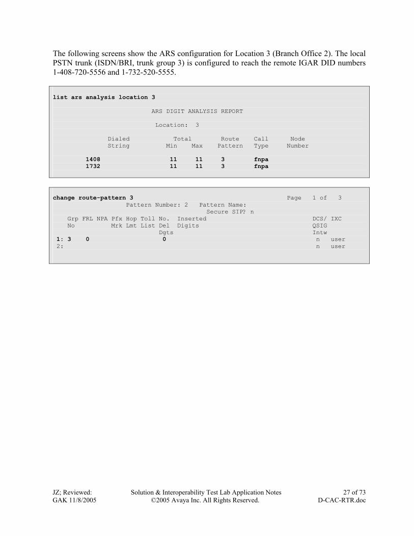
The following screens show the ARS configuration for Location 3 (Branch Office 2). The local PSTN trunk (ISDN/BRI, trunk group 3) is configured to reach the remote IGAR DID numbers 1-408-720-5556 and 1-732-520-5555. list ars analysis location 3 ARS DIGIT ANALYSIS REPORT Location: 3 Dialed Total Route Call Node String Min Max Pattern Type Number 1408 11 11 3 fnpa 1732 11 11 3 fnpa change route-pattern 3 Page 1 of 3 Pattern Number: 2 Pattern Name: Secure SIP? n Grp FRL NPA Pfx Hop Toll No. Inserted DCS/ IXC No Mrk Lmt List Del Digits QSIG Dgts Intw 1: 3 0 0 n user 2: n user
JZ; Reviewed: GAK 11/8/2005
Solution & Interoperability Test Lab Application Notes ©2005 Avaya Inc. All Rights Reserved.
27 of 73 D-CAC-RTR.doc

3.7 Configure Main and Enterprise Survivable Servers Refer to [2] and [3] for detailed ESS configuration. The section only shows related ESS configurations.
3.7.1 Verify Licenses Use the command display system-parameters customer-options on Avaya Communication Manager to verify that a correct license has been installed. The Avaya S8710 Media Servers in the Main Office are configured as Main servers. The Enterprise Survivable Server field must be set to n and the ESS Administration field must be set to y for the Main servers. display system-parameters customer-options Page 4 of 10 OPTIONAL FEATURES Emergency Access to Attendant? y IP Stations? y Enable 'dadmin' Login? y Internet Protocol (IP) PNC? n Enhanced Conferencing? y ISDN Feature Plus? y Enhanced EC500? n ISDN Network Call Redirection? y Enterprise Survivable Server? n ISDN-BRI Trunks? y Enterprise Wide Licensing? n ISDN-PRI? y ESS Administration? y Local Survivable Processor? n Extended Cvg/Fwd Admin? n Malicious Call Trace? n External Device Alarm Admin? n Media Encryption Over IP? n Five Port Networks Max Per MCC? n Mode Code for Centralized Voice Mail? y Flexible Billing? n Forced Entry of Account Codes? n Multifrequency Signaling? y Global Call Classification? n Multimedia Appl. Server Interface (MASI)? n Hospitality (Basic)? y Multimedia Call Handling (Basic)? n The Avaya S8500 Media Server in Branch Office 1 is configured as an ESS server. The Enterprise Survivable Server and the ESS Administration fields must be set to “y” for the ESS server. change system-parameters customer-options Page 4 of 10 OPTIONAL FEATURES Emergency Access to Attendant? y IP Stations? y Enable 'dadmin' Login? y Internet Protocol (IP) PNC? y Enhanced Conferencing? y ISDN Feature Plus? y Enhanced EC500? n ISDN Network Call Redirection? y Enterprise Survivable Server? y ISDN-BRI Trunks? y Enterprise Wide Licensing? n ISDN-PRI? y ESS Administration? y Local Survivable Processor? n Extended Cvg/Fwd Admin? n Malicious Call Trace? n External Device Alarm Admin? n Media Encryption Over IP? n Five Port Networks Max Per MCC? n Mode Code for Centralized Voice Mail? y Flexible Billing? n Forced Entry of Account Codes? n Multifrequency Signaling? y Global Call Classification? n Multimedia Appl. Server Interface (MASI)? n Hospitality (Basic)? y Multimedia Call Handling (Basic)? n
JZ; Reviewed: GAK 11/8/2005
Solution & Interoperability Test Lab Application Notes ©2005 Avaya Inc. All Rights Reserved.
28 of 73 D-CAC-RTR.doc

3.7.2 Configure Server Identities Each server requires a different Server Identification Number (SVID) for the ESS cluster configuration. The SVID is a number selected by the administrator when the server is configured. The following screen shows the Set Identities configuration on the active Main server maintenance Web interface. The Avaya S8710 Media Servers are assigned SVID 1 and 2, respectively.
JZ; Reviewed: GAK 11/8/2005
Solution & Interoperability Test Lab Application Notes ©2005 Avaya Inc. All Rights Reserved.
29 of 73 D-CAC-RTR.doc

The following screen shows the Configure ESS page on the Main servers. This is NOT an enterprise survivable server must be selected for the Main server(s).
JZ; Reviewed: GAK 11/8/2005
Solution & Interoperability Test Lab Application Notes ©2005 Avaya Inc. All Rights Reserved.
30 of 73 D-CAC-RTR.doc

The following screen shows the Set Identities configuration on the Avaya S8500 Media Server maintenance Web interface. The Avaya S8500 Media Server is assigned SVID 3.
JZ; Reviewed: GAK 11/8/2005
Solution & Interoperability Test Lab Application Notes ©2005 Avaya Inc. All Rights Reserved.
31 of 73 D-CAC-RTR.doc

The following screen shows the Configure ESS page on the Avaya S8500 Media Server. This is an enterprise survivable server with a S8700 Series media server as the main server must be selected. Complete the field as displayed to match the configuration on the Avaya S8710 Media Servers.
JZ; Reviewed: GAK 11/8/2005
Solution & Interoperability Test Lab Application Notes ©2005 Avaya Inc. All Rights Reserved.
32 of 73 D-CAC-RTR.doc

3.7.3 Administer ESS Server on the Main server ESS administration is performed on the SAT of the Main server using the system-parameters ess form. On the active S8710 Media Server, use the command change system-parameters ess to configure ess. The following page shows Page 1 of 7 (administer up to 63 ESS servers on Pages 1 to 5). In the sample configuration, enter SVID 3 in the Server ID field (as configured in Section 3.7.2) and 2 in the Cl ID field (the same as the Module ID (MID) from the RFA license file) for the ESS server. Set the Pri Scr (priority score) to “1”, Com (Community) to “1” and Sys Prf (System Preferred) to “y” for the ESS server. Use the Sys Prf option to keep as much of the system intact as possible, allowing one ESS server to replace the Main server. change system-parameters ess Page 1 of 7 ENTERPRISE SURVIVABLE SERVER INFORMATION Cl Plat Server A Server B Pri Com Sys Loc Loc ID Type ID IP Address ID IP Address Scr Prf Prf Only ------------------------------------------------------------------------------ MAIN SERVERS 1 Duplex 1 192.168.1 .1 2 192.168.1 .2 ENTERPRISE SURVIVABLE SERVERS 2 Simplex 3 192.168.2 .3 1 1 y n n . . . . . . 1 1 y n n . . . . . . 1 1 y n n . . . . . . 1 1 y n n . . . . . . 1 1 y n n . . . . . . 1 1 y n n . . . . . . 1 1 y n n . . . . . . 1 1 y n n Note that the MID must be different for each ESS server when a RFA license is created. The following screen shows how to find the MID on the ESS server by using the Bash command statuslicense –v. [root@server-ESS defty]# statuslicense -v CommunicaMgr License Mode: Normal checking application CommunicaMgr version R013x.00.0.340.3 License is OK Network used for License: Carrier 02a License Serial Number is 05J214700179 on Carrier 02a RFA Module ID is 2 RFA System ID is 1
JZ; Reviewed: GAK 11/8/2005
Solution & Interoperability Test Lab Application Notes ©2005 Avaya Inc. All Rights Reserved.
33 of 73 D-CAC-RTR.doc

Go to Page 6 and assign a community for a port network. In the sample configuration, the Avaya G650 Media Gateways in the main and branch offices are assigned to PN Community 1. change system-parameters ess Page 6 of 7 COMMUNITY ASSIGNMENTS FOR PORT NETWORKS PN Community PN Community PN Community PN Community PN Community ------------ ------------ ------------ ------------ ------------ 1: 1 14: 1 27: 1 40: 1 53: 1 2: 1 15: 1 28: 1 41: 1 54: 1 3: 1 16: 1 29: 1 42: 1 55: 1 4: 1 17: 1 30: 1 43: 1 56: 1 5: 1 18: 1 31: 1 44: 1 57: 1 6: 1 19: 1 32: 1 45: 1 58: 1 7: 1 20: 1 33: 1 46: 1 59: 1 8: 1 21: 1 34: 1 47: 1 60: 1 9: 1 22: 1 35: 1 48: 1 61: 1 10: 1 23: 1 36: 1 49: 1 62: 1 11: 1 24: 1 37: 1 50: 1 63: 1 12: 1 25: 1 38: 1 51: 1 64: 1 13: 1 26: 1 39: 1 52: 1 Go to Page 7 and configure the Auto Return feature and No Service Time Out Interval. Auto Return: The Auto Return functionality is used to schedule a day and time for all Port Networks to return to the control of the Main server after a failover occurs. The schedule can be set up to seven days prior to its activation. Valid values for this field are no and scheduled. When the value is set to no, no additional fields appear. When the value is set to scheduled, the day and time fields appears. No Service Time Out Interval (default 5 minutes): Enter the time, in minutes that the IPSIs will wait before requesting service from the highest ESS server on its priority list. Allowed entry for this field is 3 to 15 minutes. The No Service Time Out Interval is configured to 3 minutes in the example below. The following screen shows the configuration used in the sample configuration. change system-parameters ess Page 7 of 7 ENTERPRISE SURVIVABLE SERVER OPTIONAL FEATURES Auto Return: no No Service Time Out Interval: 3
JZ; Reviewed: GAK 11/8/2005
Solution & Interoperability Test Lab Application Notes ©2005 Avaya Inc. All Rights Reserved.
34 of 73 D-CAC-RTR.doc

3.8 Configure the Corporate and Internet VPN Networks This section provides the configurations used in these Application Notes for the corporate and Internet VPN networks. These configurations are provided for demonstration purposes only.
3.8.1 Configure the Cisco Catalyst 3750 Switch in the Main Office The following screen shows the annotated configuration for the Cisco Catalyst 3750 in the Main Office. The OSPF routing protocol is used for the corporate network. The default route is set to the private IP address of the Checkpoint VPN-1/FW-1.
JZ; Reviewed: GAK 11/8/2005
Solution & Interoperability Test Lab Application Notes ©2005 Avaya Inc. All Rights Reserved.
35 of 73 D-CAC-RTR.doc
version 12.2 no service pad service timestamps debug uptime service timestamps log uptime no service password-encryption ! hostname Switch ! enable secret 5 $1$WWUQ$cpsE5l6xt/ib3tmWPJNNr. ! no aaa new-model switch 1 provision ws-c3750-24p ip subnet-zero ip routing ! no file verify auto spanning-tree mode pvst spanning-tree extend system-id ! vlan internal allocation policy ascending ! ! Connect to the he private network of the Checkpoint interface FastEthernet1/0/1 switchport access vlan 200 switchport mode access ! interface FastEthernet1/0/2 switchport mode access ! interface FastEthernet1/0/3 switchport mode access ! interface FastEthernet1/0/4 switchport mode access ! interface FastEthernet1/0/5 switchport mode access ! interface FastEthernet1/0/6 switchport mode access ! interface FastEthernet1/0/7 switchport mode access

JZ; Reviewed: GAK 11/8/2005
Solution & Interoperability Test Lab Application Notes ©2005 Avaya Inc. All Rights Reserved.
36 of 73 D-CAC-RTR.doc
! interface FastEthernet1/0/8 switchport mode access ! interface FastEthernet1/0/9 switchport mode access ! interface FastEthernet1/0/10 switchport mode access ! interface FastEthernet1/0/11 switchport mode access ! interface FastEthernet1/0/12 switchport mode access ! interface FastEthernet1/0/13 switchport access vlan 254 switchport trunk native vlan 254 switchport mode access ! interface FastEthernet1/0/14 switchport access vlan 254 switchport mode access ! interface FastEthernet1/0/15 switchport access vlan 254 switchport mode access ! interface FastEthernet1/0/16 switchport access vlan 254 switchport mode access ! interface FastEthernet1/0/17 switchport access vlan 255 switchport mode access ! interface FastEthernet1/0/18 switchport access vlan 255 switchport mode access ! interface FastEthernet1/0/19 switchport access vlan 255 switchport mode access ! interface FastEthernet1/0/20 switchport access vlan 255 switchport mode access ! interface FastEthernet1/0/21 ! interface FastEthernet1/0/22 ! interface FastEthernet1/0/23 ! interface FastEthernet1/0/24

switchport access vlan 100 switchport mode access ! interface GigabitEthernet1/0/1 ! interface GigabitEthernet1/0/2 ! ! The Corporate LAN Network – Control Network C interface Vlan1 ip address 192.168.1.254 255.255.255.0 ! ! The Corporate Network Access interface Vlan100 ip address 192.168.100.2 255.255.255.0 ! ! The private network of the Checkpoint interface Vlan200 ip address 192.168.200.1 255.255.255.0 ! Control Network A interface Vlan254 ip address 198.152.254.254 255.255.255.0 ! ! Control Network B interface Vlan255 ip address 198.152.255.254 255.255.255.0 bridge-group 255 ! ! OSPF for the Corporate Network router ospf 1 log-adjacency-changes network 192.168.0.0 0.0.255.255 area 0 network 198.152.0.0 0.0.255.255 area 0 ! ip classless ! Default router to the Checkpoint Private IP address ip route 0.0.0.0 0.0.0.0 192.168.200.101 ip http server ! control-plane ! line con 0 password cisco line vty 0 3 password cisco no login line vty 4 no login line vty 5 15 no login ! end
JZ; Reviewed: GAK 11/8/2005
Solution & Interoperability Test Lab Application Notes ©2005 Avaya Inc. All Rights Reserved.
37 of 73 D-CAC-RTR.doc

3.8.2 Configure the Checkpoint VPN In the Main Office This section provides the VPN configuration between the Checkpoint VPN-1/FW-1 and the Cisco 1841 access routers in Branch Offices 1 and 2. Refer to the Checkpoint configuration guide for detailed information. The following shows the Check Point SmartDashboard management screen.
JZ; Reviewed: GAK 11/8/2005
Solution & Interoperability Test Lab Application Notes ©2005 Avaya Inc. All Rights Reserved.
38 of 73 D-CAC-RTR.doc

Three networks are configured as local private networks behind the Checkpoint VPN-1/FW-1:
• Control Network A: 198.152.254.0/255.255.255.0 • Control Network B: 198.152.255.0/255.255.255.0 • Corporate LAN Network: 192.168.1.0/255.255.255.0
The following screen shows that a network group named Check-Point is created to include these three networks.
JZ; Reviewed: GAK 11/8/2005
Solution & Interoperability Test Lab Application Notes ©2005 Avaya Inc. All Rights Reserved.
39 of 73 D-CAC-RTR.doc

The following screen shows the General Properties of the Checkpoint VPN-1/FW-1. 134.1.10.1 is its public interface IP address. The FireWall-1 and VPN-1 Pro boxes must be checked.
JZ; Reviewed: GAK 11/8/2005
Solution & Interoperability Test Lab Application Notes ©2005 Avaya Inc. All Rights Reserved.
40 of 73 D-CAC-RTR.doc

The following screen shows the Topology of the Checkpoint VPN-1/FW-1. 192.168.200.101 is its private IP address. The private networks behind the Checkpoint VPN-1/FW-1 are included in a group named Check-Point.
JZ; Reviewed: GAK 11/8/2005
Solution & Interoperability Test Lab Application Notes ©2005 Avaya Inc. All Rights Reserved.
41 of 73 D-CAC-RTR.doc

The following screen shows the VPN Properties.
JZ; Reviewed: GAK 11/8/2005
Solution & Interoperability Test Lab Application Notes ©2005 Avaya Inc. All Rights Reserved.
42 of 73 D-CAC-RTR.doc

Click Traditional mode configuration… from the VPN screen and configure IKE phase 1 general parameters.
Select Interoperable Devices from the Check Point SmartDashboard management screen and create two interoperable devices corresponding to the Cisco 1841 access routers in Branch Offices 1 and 2. The following shows the configuration for Branch Office 1. A similar configuration should be done for Branch Office 2. The following screen shows the General Properties of the Cisco 1841 access router in Branch Office 1. 12.160.181.101 is the public interface IP address of the Cisco 1841 access router in Branch Office 1.
JZ; Reviewed: GAK 11/8/2005
Solution & Interoperability Test Lab Application Notes ©2005 Avaya Inc. All Rights Reserved.
43 of 73 D-CAC-RTR.doc

JZ; Reviewed: GAK 11/8/2005
Solution & Interoperability Test Lab Application Notes ©2005 Avaya Inc. All Rights Reserved.
44 of 73 D-CAC-RTR.doc

The following screen shows the Topology of the Cisco 1841 access router in Branch Office 1. The private network behind Cisco 1841 access router is defined in a network object named BO-1-Network, which is configured to include network 192.168.2.0/255.255.255.0.
JZ; Reviewed: GAK 11/8/2005
Solution & Interoperability Test Lab Application Notes ©2005 Avaya Inc. All Rights Reserved.
45 of 73 D-CAC-RTR.doc

The following Screen shows the VPN Properties of the Cisco 1841 access router in Branch Office 1.
JZ; Reviewed: GAK 11/8/2005
Solution & Interoperability Test Lab Application Notes ©2005 Avaya Inc. All Rights Reserved.
46 of 73 D-CAC-RTR.doc

Click Traditional mode configuration… from the VPN screen and configure IKE phase 1 parameters to match the Cisco VPN configuration on the Cisco 1841 access router in Branch Office 1 (Section 3.8.4: crypto isakmp policy 1).
Check the Pre-shared Secret checkbox and click on the Edit Secrets… button. Configure the Shared Secret to match the configuration on the Cisco 1841 access router in Branch Office 1.
JZ; Reviewed: GAK 11/8/2005
Solution & Interoperability Test Lab Application Notes ©2005 Avaya Inc. All Rights Reserved.
47 of 73 D-CAC-RTR.doc

The following screen shows the VPN association configuration with the Cisco VPN in Branch offices 1 and 2. A network group object named BO is configured to include all the private networks (192.168.2.0/24 and 192.168.3.0/24) behind the Cisco 1841 access routers in Branch offices 1 and 2.
The following screen shows the IKE phase 2 configuration, which should match the configuration on the Cisco 1841 access routers in Branch Offices 1 and 2 (Section 3.8.4: crypto ipsec transform-set Phase2-3des esp-3des esp-sha-hmac).
JZ; Reviewed: GAK 11/8/2005
Solution & Interoperability Test Lab Application Notes ©2005 Avaya Inc. All Rights Reserved.
48 of 73 D-CAC-RTR.doc

3.8.3 Configure the Cisco 7206 Access Router In the Main Office The following screen shows the annotated configuration for the Cisco 7206 access router in the Main Office. The Cisco 7206 access router is used for the Internet access. version 12.3 service timestamps debug uptime service timestamps log uptime no service password-encryption ! hostname 7206-VPN ! boot-start-marker boot system slot1:c7200-jk9s-mz.123-8.T8.bin boot-end-marker ! enable password cisco ! no aaa new-model ip subnet-zero ! ip cef ! ! channnelized T1 configuration for the Internet Access controller T1 6/0 framing esf linecode b8zs channel-group 1 timeslots 1-24 speed 64 ! controller T1 6/1 framing esf clock source internal linecode b8zs channel-group 1 timeslots 1-24 speed 64 ! controller T1 6/2 framing esf linecode b8zs ! controller T1 6/3 framing esf linecode b8zs ! ! Connect to the public interface of the checkpoint interface FastEthernet0/0 ip address 134.1.10.2 255.255.255.0 ! ! Connect to the Internet (T1/PPP) interface Serial6/0:1 ip address 12.160.180.101 255.255.255.0 encapsulation ppp ! interface Serial6/1:1
JZ; Reviewed: GAK 11/8/2005
Solution & Interoperability Test Lab Application Notes ©2005 Avaya Inc. All Rights Reserved.
49 of 73 D-CAC-RTR.doc

no ip address encapsulation frame-relay ! ip classless ! ! Default Gateway to the Internet ip route 0.0.0.0 0.0.0.0 Serial6/0:1 no ip http server no ip http secure-server ! ! control-plane ! ! dial-peer cor custom ! ! line con 0 stopbits 1 line aux 0 stopbits 1 line vty 0 4 password cisco login ! ! end
JZ; Reviewed: GAK 11/8/2005
Solution & Interoperability Test Lab Application Notes ©2005 Avaya Inc. All Rights Reserved.
50 of 73 D-CAC-RTR.doc

3.8.4 Configure the Cisco 1841 Access Router in Branch Office 1 The following screen shows the annotated configuration on the Cisco 1841 access router in Branch Office 1. The Cisco 1841 access router is used for corporate and Internet VPN access. The OSPF routing protocol is used for the corporate network connection with the default gateway configured to the Internet gateway. In order to have a full mesh VPN network, two VPN peers have been configured for the Main Office and Branch Office 2.
JZ; Reviewed: GAK 11/8/2005
Solution & Interoperability Test Lab Application Notes ©2005 Avaya Inc. All Rights Reserved.
51 of 73 D-CAC-RTR.doc
version 12.3 service timestamps debug datetime msec service timestamps log datetime msec no service password-encryption ! hostname C1800-B1 ! boot-start-marker boot-end-marker ! logging buffered 51200 warnings ! username cisco privilege 15 secret 5 $1$DFhO$Kthq/cr4IYKS.A2otPJUk0 mmi polling-interval 60 no mmi auto-configure no mmi pvc mmi snmp-timeout 180 no aaa new-model ip subnet-zero ip cef ! ip domain name yourdomain.com ip ips po max-events 100 no ftp-server write-enable ! ! IKE policies: crypto isakmp policy 1 encr 3des authentication pre-share crypto isakmp key MySeCr address 134.1.10.1 crypto isakmp key MySeCr address 12.160.182.101 ! ! IPSec policies: crypto ipsec transform-set Phase2-3des esp-3des esp-sha-hmac ! crypto map Full-Mesh-VPN 1 ipsec-isakmp description To-Main-Office set peer 134.1.10.1 set transform-set Phase2-3des match address 100 crypto map Full-Mesh-VPN 2 ipsec-isakmp description To-Branch-Office-2 set peer 12.160.182.101 set transform-set Phase2-3des match address 101

JZ; Reviewed: GAK 11/8/2005
Solution & Interoperability Test Lab Application Notes ©2005 Avaya Inc. All Rights Reserved.
52 of 73 D-CAC-RTR.doc
! ! Connect to the corporate network interface FastEthernet0/0 ip address 192.168.101.2 255.255.255.0 duplex auto speed auto ! ! Connect to the Avaya G350 Media Gateway interface FastEthernet0/1 ip address 192.168.2.254 255.255.255.0 ip helper-address 192.168.1.100 ip virtual-reassembly duplex auto speed auto ! ! Connect to the Internet (T1/PPP) ! Apply crypto map to the interface facing the Internet interface Serial0/0/0 ip address 12.160.181.101 255.255.255.0 ip virtual-reassembly encapsulation ppp crypto map Full-Mesh-VPN ! ! OSPF routing for the corporate network. router ospf 1 log-adjacency-changes network 192.168.0.0 0.0.255.255 area 0 ! ip classless ! Default route to the Internet ip route 0.0.0.0 0.0.0.0 Serial0/0/0 ! ip http server ip http authentication local no ip http secure-server ! ! Access list 100 for the VPN traffic between Branch Office 1 and the ! Main Office access-list 100 permit ip 192.168.2.0 0.0.0.255 192.168.1.0 0.0.0.255 access-list 100 permit ip 192.168.2.0 0.0.0.255 198.152.254.0 0.0.0.255 access-list 100 permit ip 192.168.2.0 0.0.0.255 198.152.255.0 0.0.0.255 ! ! Access list 101 for the VPN traffic between Branch Office 1 and the ! Branch Office 2 access-list 101 permit ip 192.168.2.0 0.0.0.255 192.168.3.0 0.0.0.255 ! control-plane ! line con 0 login local line aux 0 line vty 0 4 line vty 5 15 ! end

Use the command show crypto isakmp sa to verify the IKE phase 1 status. The following screen shows that the IKE phase 1 security associations have been established with the Checkpoint VPN-1/FW-1 (IP: 134.1.10.1) and the Cisco 1841 access router in Branch Office 2 (IP: 12.160.182.101). C1800-B1#show crypto isakmp sa dst src state conn-id slot status 134.1.10.1 12.160.181.101 QM_IDLE 4 0 ACTIVE 12.160.181.101 12.160.182.101 QM_IDLE 5 0 ACTIVE Use the command show crypto ipsec sa to verify the IPSec status. The following screen shows that all the IPSec VPNs with the Checkpoint VPN-1/FW-1 and the Cisco 1841 access router in Branch Office 2 are up. C1800-B1#show crypto ipsec sa interface: Serial0/0/0 Crypto map tag: Full-Mesh-VPN, local addr 12.160.181.101 protected vrf: (none)
local ident (addr/mask/prot/port): (192.168.2.0/255.255.255.0/0/0) remote ident (addr/mask/prot/port): (198.152.254.0/255.255.255.0/0/0) current_peer 134.1.10.1 port 500 PERMIT, flags={origin_is_acl,} #pkts encaps: 656792, #pkts encrypt: 656792, #pkts digest: 656792 #pkts decaps: 641789, #pkts decrypt: 641789, #pkts verify: 641789 #pkts compressed: 0, #pkts decompressed: 0 #pkts not compressed: 0, #pkts compr. failed: 0 #pkts not decompressed: 0, #pkts decompress failed: 0 #send errors 5, #recv errors 20 local crypto endpt.: 12.160.181.101, remote crypto endpt.: 134.1.10.1 path mtu 1500, ip mtu 1500 current outbound spi: 0x4CF2B9AD(1290975661) inbound esp sas: spi: 0xD5D46A9(224216745) transform: esp-3des esp-sha-hmac , in use settings ={Tunnel, } conn id: 4012, flow_id: FPGA:12, crypto map: Full-Mesh-VPN sa timing: remaining key lifetime (k/sec): (4599553/955) IV size: 8 bytes replay detection support: Y Status: ACTIVE inbound ah sas: inbound pcp sas: outbound esp sas:
JZ; Reviewed: GAK 11/8/2005
Solution & Interoperability Test Lab Application Notes ©2005 Avaya Inc. All Rights Reserved.
53 of 73 D-CAC-RTR.doc

JZ; Reviewed: GAK 11/8/2005
Solution & Interoperability Test Lab Application Notes ©2005 Avaya Inc. All Rights Reserved.
54 of 73 D-CAC-RTR.doc
spi: 0x4CF2B9AD(1290975661) transform: esp-3des esp-sha-hmac , in use settings ={Tunnel, } conn id: 4011, flow_id: FPGA:11, crypto map: Full-Mesh-VPN sa timing: remaining key lifetime (k/sec): (4599029/954) IV size: 8 bytes replay detection support: Y Status: ACTIVE outbound ah sas: outbound pcp sas: protected vrf: (none) local ident (addr/mask/prot/port): (192.168.2.0/255.255.255.0/0/0) remote ident (addr/mask/prot/port): (198.152.255.0/255.255.255.0/0/0) current_peer 134.1.10.1 port 500 PERMIT, flags={origin_is_acl,} #pkts encaps: 559438, #pkts encrypt: 559438, #pkts digest: 559438 #pkts decaps: 558991, #pkts decrypt: 558991, #pkts verify: 558991 #pkts compressed: 0, #pkts decompressed: 0 #pkts not compressed: 0, #pkts compr. failed: 0 #pkts not decompressed: 0, #pkts decompress failed: 0 #send errors 4, #recv errors 24 local crypto endpt.: 12.160.181.101, remote crypto endpt.: 134.1.10.1 path mtu 1500, ip mtu 1500 current outbound spi: 0x4CF2B9B1(1290975665) inbound esp sas: spi: 0x4A22C14A(1243791690) transform: esp-3des esp-sha-hmac , in use settings ={Tunnel, } conn id: 4006, flow_id: FPGA:6, crypto map: Full-Mesh-VPN sa timing: remaining key lifetime (k/sec): (4565188/1136) IV size: 8 bytes replay detection support: Y Status: ACTIVE inbound ah sas: inbound pcp sas: outbound esp sas: spi: 0x4CF2B9B1(1290975665) transform: esp-3des esp-sha-hmac , in use settings ={Tunnel, } conn id: 4004, flow_id: FPGA:4, crypto map: Full-Mesh-VPN sa timing: remaining key lifetime (k/sec): (4565187/1136) IV size: 8 bytes replay detection support: Y Status: ACTIVE outbound ah sas: outbound pcp sas:

protected vrf: (none) local ident (addr/mask/prot/port): (192.168.2.0/255.255.255.0/0/0) remote ident (addr/mask/prot/port): (192.168.1.0/255.255.255.0/0/0) current_peer 134.1.10.1 port 500 PERMIT, flags={origin_is_acl,} #pkts encaps: 1991764, #pkts encrypt: 1991764, #pkts digest: 1991764 #pkts decaps: 2001541, #pkts decrypt: 2001541, #pkts verify: 2001541 #pkts compressed: 0, #pkts decompressed: 0 #pkts not compressed: 0, #pkts compr. failed: 0 #pkts not decompressed: 0, #pkts decompress failed: 0 #send errors 1, #recv errors 0 local crypto endpt.: 12.160.181.101, remote crypto endpt.: 134.1.10.1 path mtu 1500, ip mtu 1500 current outbound spi: 0x4CF2B9C3(1290975683) inbound esp sas: spi: 0x92E297DF(2464323551) transform: esp-3des esp-sha-hmac , in use settings ={Tunnel, } conn id: 4016, flow_id: FPGA:16, crypto map: Full-Mesh-VPN sa timing: remaining key lifetime (k/sec): (4436833/2294) IV size: 8 bytes replay detection support: Y Status: ACTIVE inbound ah sas: inbound pcp sas: outbound esp sas: spi: 0x4CF2B9C3(1290975683) transform: esp-3des esp-sha-hmac , in use settings ={Tunnel, } conn id: 4015, flow_id: FPGA:15, crypto map: Full-Mesh-VPN sa timing: remaining key lifetime (k/sec): (4436829/2294) IV size: 8 bytes replay detection support: Y Status: ACTIVE outbound ah sas: outbound pcp sas: protected vrf: (none) local ident (addr/mask/prot/port): (192.168.2.0/255.255.255.0/0/0)
remote ident (addr/mask/prot/port): (192.168.3.0/255.255.255.0/0/0) current_peer 12.160.182.101 port 500 PERMIT, flags={origin_is_acl,} #pkts encaps: 13434, #pkts encrypt: 13434, #pkts digest: 13434 #pkts decaps: 13112, #pkts decrypt: 13112, #pkts verify: 13112 #pkts compressed: 0, #pkts decompressed: 0 #pkts not compressed: 0, #pkts compr. failed: 0 #pkts not decompressed: 0, #pkts decompress failed: 0 #send errors 13, #recv errors 0
JZ; Reviewed: GAK 11/8/2005
Solution & Interoperability Test Lab Application Notes ©2005 Avaya Inc. All Rights Reserved.
55 of 73 D-CAC-RTR.doc

local crypto endpt.: 12.160.181.101, remote crypto endpt.: 12.160.182.101 path mtu 1500, ip mtu 1500 current outbound spi: 0x7A047A35(2047113781) inbound esp sas: spi: 0xB73C991D(3074201885) transform: esp-3des esp-sha-hmac , in use settings ={Tunnel, } conn id: 4013, flow_id: FPGA:13, crypto map: Full-Mesh-VPN sa timing: remaining key lifetime (k/sec): (4415675/826) IV size: 8 bytes replay detection support: Y Status: ACTIVE inbound ah sas: inbound pcp sas: outbound esp sas: spi: 0x7A047A35(2047113781) transform: esp-3des esp-sha-hmac , in use settings ={Tunnel, } conn id: 4007, flow_id: FPGA:7, crypto map: Full-Mesh-VPN sa timing: remaining key lifetime (k/sec): (4415694/826) IV size: 8 bytes replay detection support: Y Status: ACTIVE outbound ah sas: outbound pcp sas:
JZ; Reviewed: GAK 11/8/2005
Solution & Interoperability Test Lab Application Notes ©2005 Avaya Inc. All Rights Reserved.
56 of 73 D-CAC-RTR.doc

3.8.5 Configure the Cisco 1841 Access Router in Branch Office 2 The following screen shows the annotated configuration on the Cisco 1841 access router in Branch Office 2. The Cisco 1841 access router is used forcorporate and the Internet VPN access. The OSPF routing protocol is used for the corporate network with the default gateway set to the Internet gateway. In order to have a full mesh VPN network, two VPN peers have been configured corresponding to the Main Office and Branch Office 1.
JZ; Reviewed: GAK 11/8/2005
Solution & Interoperability Test Lab Application Notes ©2005 Avaya Inc. All Rights Reserved.
57 of 73 D-CAC-RTR.doc
version 12.3 service timestamps debug datetime msec service timestamps log datetime msec no service password-encryption ! hostname C1800-B2 ! boot-start-marker boot system flash c1841-advipservicesk9-mz.123-11.T3.bin boot-end-marker ! enable password cisco ! mmi polling-interval 60 no mmi auto-configure no mmi pvc mmi snmp-timeout 180 no aaa new-model ip subnet-zero ip cef ! no ip domain lookup ip ips po max-events 100 frame-relay switching no ftp-server write-enable ! ! IKE policies: crypto isakmp policy 1 encr 3des authentication pre-share crypto isakmp key MySeCr address 134.1.10.1 crypto isakmp key MySeCr address 12.160.181.101 ! ! IPSec policies: crypto ipsec transform-set Phase2-3des esp-3des esp-sha-hmac ! crypto map Full-Mesh-VPN 1 ipsec-isakmp description To-Main-Office set peer 134.1.10.1 set transform-set Phase2-3des match address 100 crypto map Full-Mesh-VPN 2 ipsec-isakmp description To-Branch-Office-1 set peer 12.160.181.101 set transform-set Phase2-3des match address 101

! ! Connect to the corporate network interface FastEthernet0/0 ip address 192.168.102.2 255.255.255.0 duplex auto speed auto ! ! Connect to the G250-BRI Media Gateway interface FastEthernet0/1 ip address 192.168.3.254 255.255.255.0 ip nat inside ip virtual-reassembly duplex auto speed auto ! ! Connect to the Internet (T1/PPP) ! Apply crypto map to the interface facing the Internet interface Serial0/0/0 ip address 12.160.182.101 255.255.255.0 encapsulation ppp no fair-queue crypto map Full-Mesh-VPN ! ! OSPF routing for the corporate network. router ospf 1 log-adjacency-changes network 192.168.0.0 0.0.255.255 area 0 ! ip classless ! Default route to the Internet ip route 0.0.0.0 0.0.0.0 Serial0/0/0 ! ! ip http server no ip http secure-server ! ! Access list 100 for the VPN traffic between Branch Office 2 and the ! Main Office access-list 100 permit ip 192.168.3.0 0.0.0.255 192.168.1.0 0.0.0.255 access-list 100 permit ip 192.168.3.0 0.0.0.255 198.152.254.0 0.0.0.255 access-list 100 permit ip 192.168.3.0 0.0.0.255 198.152.255.0 0.0.0.255 ! Access list 101 for the VPN traffic between Branch Office 1 and the ! Branch Office 1 access-list 101 permit ip 192.168.3.0 0.0.0.255 192.168.2.0 0.0.0.255 ! ! control-plane ! line con 0 line aux 0 line vty 0 4 password cisco login ! end
JZ; Reviewed: GAK 11/8/2005
Solution & Interoperability Test Lab Application Notes ©2005 Avaya Inc. All Rights Reserved.
58 of 73 D-CAC-RTR.doc

Use the command show crypto isakmp sa to verify the IKE phase 1 status. The following screen shows that the IKE phase 1 security associations have been established with the Checkpoint VPN-1/FW-1 (IP: 134.1.10.1) and the Cisco 1841 access router in Branch Office 1 (IP: 12.160.181.101). C1800-B2#show crypto isakmp sa dst src state conn-id slot status 12.160.181.101 12.160.182.101 QM_IDLE 2 0 ACTIVE 134.1.10.1 12.160.182.101 QM_IDLE 1 0 ACTIVE Use the command show crypto ipsec sa to verify the IPSec status. The following screen shows that all the IPSec VPNs with the Checkpoint VPN-1/FW-1 and the Cisco 1841 access router in Branch Office 1 are up. C1800-B2#show crypto ipsec sa interface: Serial0/0/0 Crypto map tag: Full-Mesh-VPN, local addr 12.160.182.101 protected vrf: (none) local ident (addr/mask/prot/port): (192.168.3.0/255.255.255.0/0/0) remote ident (addr/mask/prot/port): (198.152.254.0/255.255.255.0/0/0) current_peer 134.1.10.1 port 500 PERMIT, flags={origin_is_acl,} #pkts encaps: 31, #pkts encrypt: 31, #pkts digest: 31 #pkts decaps: 15, #pkts decrypt: 15, #pkts verify: 15 #pkts compressed: 0, #pkts decompressed: 0 #pkts not compressed: 0, #pkts compr. failed: 0 #pkts not decompressed: 0, #pkts decompress failed: 0 #send errors 2, #recv errors 0 local crypto endpt.: 12.160.182.101, remote crypto endpt.: 134.1.10.1 path mtu 1500, ip mtu 1500 current outbound spi: 0x4CF2B9D5(1290975701) inbound esp sas: spi: 0x4F5B3DB(83211227) transform: esp-3des esp-sha-hmac , in use settings ={Tunnel, } conn id: 4009, flow_id: FPGA:9, crypto map: Full-Mesh-VPN sa timing: remaining key lifetime (k/sec): (4506376/3574) IV size: 8 bytes replay detection support: Y Status: ACTIVE inbound ah sas: inbound pcp sas:
JZ; Reviewed: GAK 11/8/2005
Solution & Interoperability Test Lab Application Notes ©2005 Avaya Inc. All Rights Reserved.
59 of 73 D-CAC-RTR.doc

JZ; Reviewed: GAK 11/8/2005
Solution & Interoperability Test Lab Application Notes ©2005 Avaya Inc. All Rights Reserved.
60 of 73 D-CAC-RTR.doc
outbound esp sas: spi: 0x4CF2B9D5(1290975701) transform: esp-3des esp-sha-hmac , in use settings ={Tunnel, } conn id: 4010, flow_id: FPGA:10, crypto map: Full-Mesh-VPN sa timing: remaining key lifetime (k/sec): (4506376/3572) IV size: 8 bytes replay detection support: Y Status: ACTIVE outbound ah sas: outbound pcp sas: protected vrf: (none) local ident (addr/mask/prot/port): (192.168.3.0/255.255.255.0/0/0) remote ident (addr/mask/prot/port): (198.152.255.0/255.255.255.0/0/0) current_peer 134.1.10.1 port 500 PERMIT, flags={origin_is_acl,} #pkts encaps: 16, #pkts encrypt: 16, #pkts digest: 16 #pkts decaps: 7, #pkts decrypt: 7, #pkts verify: 7 #pkts compressed: 0, #pkts decompressed: 0 #pkts not compressed: 0, #pkts compr. failed: 0 #pkts not decompressed: 0, #pkts decompress failed: 0 #send errors 2, #recv errors 0 local crypto endpt.: 12.160.182.101, remote crypto endpt.: 134.1.10.1 path mtu 1500, ip mtu 1500 current outbound spi: 0x4CF2B9D6(1290975702) inbound esp sas: spi: 0x9F0D192A(2668435754) transform: esp-3des esp-sha-hmac , in use settings ={Tunnel, } conn id: 4008, flow_id: FPGA:8, crypto map: Full-Mesh-VPN sa timing: remaining key lifetime (k/sec): (4535389/3576) IV size: 8 bytes replay detection support: Y Status: ACTIVE inbound ah sas: inbound pcp sas: outbound esp sas: spi: 0x4CF2B9D6(1290975702) transform: esp-3des esp-sha-hmac , in use settings ={Tunnel, } conn id: 4007, flow_id: FPGA:7, crypto map: Full-Mesh-VPN sa timing: remaining key lifetime (k/sec): (4535389/3576) IV size: 8 bytes replay detection support: Y Status: ACTIVE outbound ah sas:

outbound pcp sas: protected vrf: (none) remote ident (addr/mask/prot/port): (192.168.1.0/255.255.255.0/0/0)
local ident (addr/mask/prot/port): (192.168.3.0/255.255.255.0/0/0)
current_peer 134.1.10.1 port 500 PERMIT, flags={origin_is_acl,} #pkts encaps: 120347, #pkts encrypt: 120347, #pkts digest: 120347 #pkts decaps: 120300, #pkts decrypt: 120300, #pkts verify: 120300 #pkts compressed: 0, #pkts decompressed: 0 #pkts not compressed: 0, #pkts compr. failed: 0 #pkts not decompressed: 0, #pkts decompress failed: 0 #send errors 15, #recv errors 0 local crypto endpt.: 12.160.182.101, remote crypto endpt.: 134.1.10.1 path mtu 1500, ip mtu 1500 current outbound spi: 0x4CF2B9AA(1290975658) inbound esp sas: spi: 0x1C82512F(478302511) transform: esp-3des esp-sha-hmac , in use settings ={Tunnel, } conn id: 4012, flow_id: FPGA:12, crypto map: Full-Mesh-VPN sa timing: remaining key lifetime (k/sec): (4591082/980) IV size: 8 bytes replay detection support: Y Status: ACTIVE inbound ah sas: inbound pcp sas: outbound esp sas: spi: 0x4CF2B9AA(1290975658) transform: esp-3des esp-sha-hmac , in use settings ={Tunnel, } conn id: 4011, flow_id: FPGA:11, crypto map: Full-Mesh-VPN sa timing: remaining key lifetime (k/sec): (4591079/980) IV size: 8 bytes replay detection support: Y Status: ACTIVE outbound ah sas: outbound pcp sas: protected vrf: (none)
local ident (addr/mask/prot/port): (192.168.3.0/255.255.255.0/0/0) remote ident (addr/mask/prot/port): (192.168.2.0/255.255.255.0/0/0) current_peer 12.160.181.101 port 500 PERMIT, flags={origin_is_acl,} #pkts encaps: 13050, #pkts encrypt: 13050, #pkts digest: 13050 #pkts decaps: 13372, #pkts decrypt: 13372, #pkts verify: 13372 #pkts compressed: 0, #pkts decompressed: 0 #pkts not compressed: 0, #pkts compr. failed: 0 #pkts not decompressed: 0, #pkts decompress failed: 0
JZ; Reviewed: GAK 11/8/2005
Solution & Interoperability Test Lab Application Notes ©2005 Avaya Inc. All Rights Reserved.
61 of 73 D-CAC-RTR.doc

#send errors 2, #recv errors 0 local crypto endpt.: 12.160.182.101, remote crypto endpt.: 12.160.181.101 path mtu 1500, ip mtu 1500 current outbound spi: 0xB73C991D(3074201885) inbound esp sas: spi: 0x7A047A35(2047113781) transform: esp-3des esp-sha-hmac , in use settings ={Tunnel, } conn id: 4001, flow_id: FPGA:1, crypto map: Full-Mesh-VPN sa timing: remaining key lifetime (k/sec): (4453217/992) IV size: 8 bytes replay detection support: Y Status: ACTIVE inbound ah sas: inbound pcp sas: outbound esp sas: spi: 0xB73C991D(3074201885) transform: esp-3des esp-sha-hmac , in use settings ={Tunnel, } conn id: 4003, flow_id: FPGA:3, crypto map: Full-Mesh-VPN sa timing: remaining key lifetime (k/sec): (4453199/992) IV size: 8 bytes replay detection support: Y Status: ACTIVE outbound ah sas: outbound pcp sas:
JZ; Reviewed: GAK 11/8/2005
Solution & Interoperability Test Lab Application Notes ©2005 Avaya Inc. All Rights Reserved.
62 of 73 D-CAC-RTR.doc

4 Verification Steps
4.1 Under Normal Operation Under normal operation, the ESS server and the Avaya S8300 Media Server LSP should register to the Main server in the Main Office and the Main server will control all the Media Gateways. Use the status ess cluster command to verify that the ESS is registered with the Main server and the translation file is updated successfully. Use the display lsp command to verify that the LSP is registered with the Main server and the translation is updated successfully. Translation changes can be distributed from the Main server to the ESS server or the LSP by executing the save translation all command. Translation changes can also be distributed from the Main server to the ESS server by executing the save translations ess command or to the LSP by executing the save translations lsp command. Saving translation, including sending the translations to the ESS servers and LSP servers, can be performed during routine Avaya Communication Manager maintenance. Avaya Communication Manager scheduled maintenance is administered on the system-parameters maintenance form. status ess clusters Cluster ID 1 ESS CLUSTER INFORMATION Active Cluster Server Translations Software ID Enabled? ID Registered? Updated Version 1 y 2 y 22:00 9/14/2005 R013x.00.0.340.3 2 y 3 y 16:21 9/12/2005 R013x.00.0.340.3 display lsp Page 1 of 16 LOCAL SURVIVABLE PROCESSOR Number Name IP Address Service Translations State? Updated 1 LSP-B2 192.168.3 .9 in-service/idle 16:21 9/12/2005 2 . . . out-of-service Use the status ess port-networks command to verify that the Main server controls all the Avaya G650 Media Gateways or port networks successfully. When the Main server controls an Avaya G650 Media Gateway, the Port Ntwk Ste field for that port network should be in the up state. Use the command list media-gateway to verify that the Avaya G350 and G250-BRI Media Gateways have registered to the Main server. When an Avaya G250-BRI or G350 Media Gateway is registered to the Main server, the Reg? field should be y. The IP address/Cntrl IP Addr field shows the IP address of the Avaya G250-BRI/G350 Media Gateway and the controller IP address. Use the command status media-gateways to troubleshoot any problems for an Avaya Media Gateway registration.
JZ; Reviewed: GAK 11/8/2005
Solution & Interoperability Test Lab Application Notes ©2005 Avaya Inc. All Rights Reserved.
63 of 73 D-CAC-RTR.doc

status ess port-networks Cluster ID 1 ESS PORT NETWORK INFORMATION Port IPSI Pri/ Pri/ Cntl Connected Com Intf Intf Ntwk Gtway Sec Sec Clus Clus(ter) PN Num Loc Type Ste Loc Loc State ID IDs 1 1 1B01 IPSI up 1B01 1A01 standby 1 1 2 1B01 actv-aa 1 1 2 2 1 2A01 IPSI up 2A01 2A01 actv-aa 1 1 2 list media-gateway MEDIA-GATEWAY REPORT Num Name Serial No/ IP Address/ Type NetRgn Reg? FW Ver/HW Vint Cntrl IP Addr RecRule 1 G350 B1 03IS71597715 192.168.2 .100 g350 2 y 24 .17 .0 /1 192.168.1 .10 none 2 G250-BRI 04IS52658365 192.168.3 .100 g250-bri 3 y 24 .17 .0 /0 192.168.1 .10 none
Use the command status ip-network–region <NR #> to verify that the correct Dynamic CAC value has been reported to the Main server. When Branch offices 1 and 2 have corporate network connections with the Main Office, the high priority CAC values (Sections 3.1 and 3.2) will be reported to Avaya Communication Manager. status ip-network-region 1 Inter Network Region Bandwidth Status Number of # Times Src Dst Conn Conn BW-limit BW-Used(Kbits) Connections BW-Limit IGAR Rgn Rgn Type Stat Tx Rx Tx Rx Hit Today Now/Today 1 2 direct pass 1540 Dynamic 0 0 0 0 0 0/ 0 1 3 direct pass 1540 Dynamic 0 0 0 0 0 0/ 0
JZ; Reviewed: GAK 11/8/2005
Solution & Interoperability Test Lab Application Notes ©2005 Avaya Inc. All Rights Reserved.
64 of 73 D-CAC-RTR.doc
status ip-network-region 2 Inter Network Region Bandwidth Status Number of # Times Src Dst Conn Conn BW-limit BW-Used(Kbits) Connections BW-Limit IGAR Rgn Rgn Type Stat Tx Rx Tx Rx Hit Today Now/Today 2 1 direct pass 1540 Dynamic 0 0 0 0 0 0/ 0 2 3 indirect pass 0/ 0

If Branch Office 2 has only Internet VPN access in the sample configuration, the calls between the Main Office and Branch Office 1 will be based on the D-CAC value and the calls between the Main and Branch Office 2 or between Branch Offices 1 and 2 will be forced to be IGAR calls. For verification purposes, make one phone call between network regions 1 and 2 and another phone call between network regions 1 and 3. Use the command status ip-network-region 1 to verify the status for these two calls. The Number of Connections field shows the number of active VoIP calls and the BW-Used field shows the bandwidth used for these calls. The IGAR Now/Today field shows the current/history number of IGAR calls. As shown in the following screen, the call between network regions 1 and 2 is a VoIP call and the bandwidth used for this call is 27 kbps (G.729 Codec). The call between the network regions 1 and 3 is an IGAR call.
status ip-network-region 1 Inter Network Region Bandwidth Status Number of # Times Src Dst Conn Conn BW-limit BW-Used(Kbits) Connections BW-Limit IGAR Rgn Rgn Type Stat Tx Rx Tx Rx Hit Today Now/Today 1 2 direct pass 1540 Dynamic 27 27 1 1 0 0/ 0 1 3 direct pass NoLimit 0 0 0 0 0 1/ 1 Make one phone call between network regions 2 and 3. Use the command status ip-network-region 2 or 3 to verify the call is an IGAR call. status ip-network-region 2 Inter Network Region Bandwidth Status Number of # Times Src Dst Conn Conn BW-limit BW-Used(Kbits) Connections BW-Limit IGAR Rgn Rgn Type Stat Tx Rx Tx Rx Hit Today Now/Today 2 1 direct pass 1540 Dynamic 0 0 0 0 0 0/ 0 2 3 direct pass NoLimit 0 0 0 0 0 1/ 1
JZ; Reviewed: GAK 11/8/2005
Solution & Interoperability Test Lab Application Notes ©2005 Avaya Inc. All Rights Reserved.
65 of 73 D-CAC-RTR.doc

If necessary, use the command list trace station <ext.> to troubleshoot IGAR problems. The following screen shows a correct IGAR trace between network regions 2 and 3. As shown in the following screen, the IGAR call is triggered, and then the IGAR LDN 2126205555 of network region 2 is dialed. The local PSTN trunk (trunk group 2) is used based on a multiple location dial plan. The IGAR call becomes active after the call is recognized as an IGAR call. list trace station 6200000 Page 1 LIST TRACE time data 13:40:48 idle station 6200000 cid 0xb13 13:40:49 active station 6200000 cid 0xb16 13:40:49 G711MU ss:off ps:20 rn:3/3 192.168.3.202:2186 192.168.3.100:2066 13:40:49 xoip: fax:Relay modem:off tty:US uid:0x8c86 cid:0xb16 13:40:52 dial 5200000 13:40:52 ring station 5200000 cid 0xb16 13:40:52 IGAR starting call app A station 5200000 cid 0xb16 13:40:52 G711MU ss:off ps:20 rn:2/2 192.168. 2.200:2710 192.168.2.11:2540 13:40:52 dial 1212620 route:PREFIX|FNPA|ARS 13:40:52 term trunk-group 2 cidd 0xb17 13:40:52 dial 12126205555 route:PREFIX|FNPA|ARS 13:40:52 route-pattern 2 preference 1 cid 0xb17 13:40:52 seize trunk-group 2 member 14 cid 0xb17 13:40:52 Setup digits 2126205555 13:40:52 Calling Number & Name NO-CPNumber EXT 7205555 13:40:52 Proceed trunk-group 2 member 14 cid 0xb17 13:40:52 tone-receiver 02AXX03 cid 0xb17 13:40:52 Alert trunk-group 2 member 14 cid 0xb17 13:40:53 active trunk-group 2 member 14 cid 0xb17 13:40:54 IGAR active call app A trunks 2/14 & 3/1 cids 0xb17 & 0xb18
JZ; Reviewed: GAK 11/8/2005
Solution & Interoperability Test Lab Application Notes ©2005 Avaya Inc. All Rights Reserved.
66 of 73 D-CAC-RTR.doc

4.2 If the Branch Offices Lose the Corporate Network Connection If a branch office loses the corporate network connection, the Avaya G250/G350 Media Gateway in that office will detect the failure and report the Dynamic CAC value with a low priority, which is zero in the sample configuration. The following screen shows that the tracked loopback interface 1 is down when Branch Office 1 loses the corporate network connection. G350-001(super)# show interfaces Loopback 1 Loopback 1 is up, line protocol is up, keepalive-track is down MTU 1514 bytes, Bandwidth 8000000 kbit Reliability 255/255 txLoad 1/255 rxLoad 1/255 Encapsulation LOOPBACK Link status trap disabled Keepalive-track set (track 1) Dynamic CAC BBL: 1540 kbps Dynamic CAC activation priority : 255 Dynamic CAC interface status : inactive Last input never, Last output never Last clearing of 'show interface' counters never 5 minute input rate 0 bits/sec, 0 packets/sec 5 minute output rate 0 bits/sec, 0 packets/sec 0 input drops, 0 output drops, 0 unknown protocols 0 packets input, 0 bytes 0 broadcasts received, 0 giants 0 input errors, 0 CRC 0 packets output, 0 bytes 0 output errors, 0 collisions Use the show dynamic-cac command on the Avaya G350 Media Gateway to verify that the CAC value zero was sent from the Avaya G350 Media Gateway. G350-001(super)# show dynamic-cac Current RBBL : 0 kbps Last event : 0 Days, 00:06:22 Last event BBL: 0 kbps Use the status ip-network-region <NR #> command on Avaya Communication Manager to verify that CAC value zero has been received via the Internet VPN connection. status ip-network-region 1 Inter Network Region Bandwidth Status Number of # Times Src Dst Conn Conn BW-limit BW-Used(Kbits) Connections BW-Limit IGAR Rgn Rgn Type Stat Tx Rx Tx Rx Hit Today Now/Today 1 2 direct pass 0 Dynamic 0 0 0 0 1 0/ 0 1 3 direct pass 1540 Dynamic 0 0 0 0 0 0/ 1
JZ; Reviewed: GAK 11/8/2005
Solution & Interoperability Test Lab Application Notes ©2005 Avaya Inc. All Rights Reserved.
67 of 73 D-CAC-RTR.doc

Based on the sample configuration, all the calls to and from network region 2 should be IGAR calls when Branch Office 1 loses its corporate network connection. Make one phone call between network regions 1 and 2, and make another phone call between network regions 2 and 3, and use the command status ip-nework-regioin 2 to verify that both calls are IGAR calls. status ip-network-region 2 Inter Network Region Bandwidth Status Number of # Times Src Dst Conn Conn BW-limit BW-Used(Kbits) Connections BW-Limit IGAR Rgn Rgn Type Stat Tx Rx Tx Rx Hit Today Now/Today 2 1 direct pass 0 Dynamic 0 0 0 0 15 1/ 1 2 3 indirect pass 1/ 4 When the corporate network connection to Branch Office 1 is restored, the Avaya G350 Media Gateway will bring loopback interface 1 up, and report the Dynamic CAC value with a high priority.
4.3 If Both the Avaya S8710 Media Servers Are Out Of Service When both Main servers are out of service, the ESS server will control all the Media Gateways (G650, G350 and G250). The IP telephones in Branch Office 2 will register to the Avaya G650 Media Gateway in the Main Office. All the features including IGAR will work the same as described in Sections 4.1 and 4.2. The commands described in Sections 4.1 and 4.2 can be used to verify the operation. When the Main servers are restored, control of the Avaya G650 Media Gateways can be transferred from the ESS server to the Main servers based on the scheduled Auto-Return if the Auto Return feature (Section 3.7.3) is configured. If Auto Return is set to no, use the command get forced-takeover ipserver-interface all on the Main server to manually bring all the Avaya G650 Media Gateways back under control of the Main server. get forced-takeover ipserver-interface all TEST RESULTS Port Maintenance Name Alt. Name Test No. Result Error Code PN 01 IPSV-CTL 1605 IN PROGRESS PN 02 IPSV-CTL 1605 IN PROGRESS Use the command status ess port-network on the Main server to verify that all the Avaya G650 Media Gateways are under control of the Main servers. Use the command list media-gateway to verify that the Avaya G350 and G250-BRI Media Gateways are registered to the Main servers via the C-LANs of the Avaya G650 Media Gateways.
JZ; Reviewed: GAK 11/8/2005
Solution & Interoperability Test Lab Application Notes ©2005 Avaya Inc. All Rights Reserved.
68 of 73 D-CAC-RTR.doc

4.4 If the Main Office Loses Both Corporate and the Internet VPN Access
If the Main Office loses both corporate and the Internet VPN access, the Main servers can only control the local Avaya G650 Media Gateway. The Avaya G650 Media Gateway in Branch Office 1 will register to the ESS server after it loses its registration with the Main servers (based on the No Service Time Out Interval in Section 3.7.3), and the ESS server will become active. The Avaya G350 Media Gateway in Branch Office 1 and the Avaya G250-BRI Media Gateway in Branch Office 2 will register to the ESS server via the C-LAN of the Avaya G650 Media Gateway in Branch Office 1. When the ESS server receives a gatekeeper request (GRQ) message from an IP endpoint destined to a C-LAN in the Avaya G650 Media Gateway, the ESS server will accept the GRQ if the C-LAN and the IP endpoint are configured to the same network region, or different regions configured with direct WAN. The ESS server will reject the GRQ if a direct WAN is not configured between these two network regions. The IP telephones in Branch Office 1 will register to the C-LAN of the Avaya G650 Media Gateway in Branch Office 1 successfully since they are configured to be in the same network region 2. If Branch Office 2 has only Internet VPN access, and a direct WAN is configured between network regions 2 and 3 (Section 3.6), the IP telephones in Branch Office 2 will register to the ESS server successfully. If Branch Office 2 has both corporate and the Internet VPN access and a direct WAN is not configured between network regions 2 and 3 (Section 3.6, direct WAN to n), the ESS server will reject the GRQ message from the IP telephone in Branch Office 2. The workaround is to add another C-LAN to the Avaya G650 Media Gateway in Branch Office 1 and configure that C-LAN to a different network region, for example network region 4, and configure a direct WAN between network regions 3 and 4. The following screen shows that a backup C-LAN in Branch Office 1 is configured to be in network region 4. change ip-interface 02a14 Page 1 of 1 IP INTERFACES Type: C-LAN Slot: 02A14 Code/Suffix: TN799 C Node Name: clan-backup IP Address: 192.168.2 .20 Subnet Mask: 255.255.255.0 Gateway Address: 192.168.2 .254 Enable Ethernet Port? y Network Region: 4 VLAN: n Number of CLAN Sockets Before Warning: 400
JZ; Reviewed: GAK 11/8/2005
Solution & Interoperability Test Lab Application Notes ©2005 Avaya Inc. All Rights Reserved.
69 of 73 D-CAC-RTR.doc

The following screen shows that direct WAN is configured between network regions 3 and 4. change ip-network-region 4 Page 3 of 19 Inter Network Region Connection Management src dst codec direct Dynamic CAC rgn rgn set WAN WAN-BW-limits Intervening-regions Gateway IGAR 4 1 4 2 4 3 2 y :NoLimit n 4 4 1
4.5 If the Corporate Network and the Internet VPN Are Out of Service
When both the corporate network and the Internet VPN are out of service for all the offices, a single server system will be split into three single-server systems:
• The Main server controls only the Avaya G650 Media Gateway in the Main Office. • The ESS server only controls the Avaya G650 and G350 Media Gateways in Branch
Office 1. • The Avaya S8300 Media Server LSP controls only the Avaya G250-BRI Media
Gateway in Branch Office 2.
The current Avaya IGAR feature is designed to work on a single-server system. The IGAR feature stops working when a single server system is split. A user in each office can reach another office by using the local PSTN facilities. The dialing plan in each office can also be manually changed so that the local PSTN facilities will be used when a user dials an extension in another office.
5 Conclusion As illustrated by these Application Notes, the Avaya IGAR feature works well with the Dynamic CAC feature in a complex network environment. When the Avaya RTR feature configured on an Avaya G250 or G350 Media Gateway detects a failure on a primary link, a different CAC value, which will decide how many calls are supported between a network region pair, can be reported to the Media Gateway controller via a secondary or backup link. The IGAR feature can also be forced as required for a network region pair. If there is any failure on the network or the Main servers, the ESS server can be used to back up the Main server and keep a single-server system as much as possible. The Avaya S8300 Media Server LSP in a branch office can be used as the last survivable controller.
JZ; Reviewed: GAK 11/8/2005
Solution & Interoperability Test Lab Application Notes ©2005 Avaya Inc. All Rights Reserved.
70 of 73 D-CAC-RTR.doc

6 Additional References The following Applications Notes can be found at http://www.avaya.com. [1] Configuring Avaya Communication Manager for Avaya S8700 Media Servers and
Avaya G600 Media Gateways Controlling Avaya G350 Media Gateways with Avaya S8300 Media Servers as Local Survivable Processors
[2] Glossary Sample Avaya S8710 Media Servers IP Connect Enterprise Survivable Server
(ESS) Configuration The following document can be found at http://support.avaya.com. [3] Avaya Enterprise Survivable Server (ESS) User Guide, Issue 1.1, June 2005, Document
ID: 03-300428
JZ; Reviewed: GAK 11/8/2005
Solution & Interoperability Test Lab Application Notes ©2005 Avaya Inc. All Rights Reserved.
71 of 73 D-CAC-RTR.doc

7 Glossary Technical Term Definition as it pertains to this document
IPSI IP Server Interface C-LAN Control-LAN MEDPRO Media Processor SAT System Access Terminal Codec Coder/Decoder ESS Enterprise Survivable Server LSP Local Survivable Processor VoIP Voice over IP RTR Respond Time Report CAC Call Admission Control
JZ; Reviewed: GAK 11/8/2005
Solution & Interoperability Test Lab Application Notes ©2005 Avaya Inc. All Rights Reserved.
72 of 73 D-CAC-RTR.doc

JZ; Reviewed: GAK 11/8/2005
Solution & Interoperability Test Lab Application Notes ©2005 Avaya Inc. All Rights Reserved.
73 of 73 D-CAC-RTR.doc
©2005 Avaya Inc. All Rights Reserved. Avaya and the Avaya Logo are trademarks of Avaya Inc. All trademarks identified by ® and ™ are registered trademarks or trademarks, respectively, of Avaya Inc. All other trademarks are the property of their respective owners. The information provided in these Application Notes is subject to change without notice. The configurations, technical data, and recommendations provided in these Application Notes are believed to be accurate and dependable, but are presented without express or implied warranty. Users are responsible for their application of any products specified in these Application Notes. Please e-mail any questions or comments pertaining to these Application Notes along with the full title name and filename, located in the lower right corner, directly to the Avaya Solution & Interoperability Test Lab at [email protected]