Embed Size (px)
Citation preview

2013 Resource Options Report Update
Appendix 9-B
Mica Pumped Storage Report

This document contains confidential information intended only for the person(s) to whom it is addressed. The information in this document may not be disclosed to, or used by, any other person without Hatch's prior written consent.
BC Hydro
Pumped Storage at Mica Generating Station
Preliminary Cost Estimate
H336793, Rev. 0 December 2010
2013 Resource Options Report Update Appendix 9-B
Page 1 of 53

~ HATCHTM
BC Hydro Pumped Storage at Mica Generating Station
Preliminary Cost Estimate
Prepared by:
Peter Rodrigue, P.Eng.
Prepared by:
Randolph Koob, P.Eng.
Reviewed by:
Distribution List
Sanjaya De Zoysa, BC Hydro
Nadja Holowaty, BC Hydro.
Hl36793.{)()()()().00.124-000I.Do<:
1 December 201 0
Date
1 December 201 0
Date
1 December 201 0
Date
H336793, Rev.O, Pagei
c Hatch 2006103 X
2013 Resource Options Report Update Appendix 9-B
Page 2 of 53

BC Hydro - Pumped Storage at Mica Generating Station Preliminary Cost Estimate
H336793, Rev. 0, Page ii
H336793-00000-00-124-0001.Doc © Hatch 2006/03
Disclaimer
This report has been prepared by Hatch Ltd. (“Hatch”) for the sole and exclusive use of BC Hydro (the “Client”) for the purpose of assisting the management of the Client in making decisions with respect to the potential development of pumped storage capability at Mica Generating Station; and shall not be (a) used for any other purpose, or (b) provided to, relied upon or used by any third party.
This report contains opinions, conclusions and recommendations made by Hatch, using its professional judgment and reasonable care. The estimate has been prepared by Hatch, using its professional judgment and exercising due care consistent with the agreed level of accuracy. Use of or reliance upon this report and estimate by Client is subject to the following conditions:
(a) the report and estimate being read in the context of and subject to the terms of the Purchase Order between
Hatch and the Client dated September 22, 2010 (the “Agreement”), including any methodologies, procedures, techniques, assumptions and other relevant terms or conditions that were specified or agreed therein;
(b) the report, including the estimate contained herein, being read as a whole, with sections or parts hereof read or relied upon in context;
(c) the conditions of the site may change over time due to natural forces or human intervention, and Hatch takes no responsibility for the impact that such changes may have on the accuracy or validity or the observations, conclusions and recommendations set out in this report;
(d) the estimate is based on several factors over which Hatch has no control including without limitation, site conditions, cost and availability of inputs etc, and Hatch takes no responsibility for the impact that changes to these factors may have on the accuracy or validity of this estimate; and
(e) the report and estimate are based on information made available to Hatch by the Client or by certain third parties; and unless stated otherwise in the Agreement, Hatch has not verified the accuracy, completeness or validity of such information, makes no representation regarding its accuracy and hereby disclaims any liability in connection therewith.
2013 Resource Options Report Update Appendix 9-B
Page 3 of 53

BC Hydro - Pumped Storage at Mica Generating Station Preliminary Cost Estimate
H336793, Rev. 0, Page iii
H336793-00000-00-124-0001.Doc © Hatch 2006/03
Table of Contents
Executive Summary........................................................................................................................................ v
1. Introduction ............................................................................................................................................ 1
2. Pumped Storage Concept ........................................................................................................................ 2
3. Hydraulic Conditions for Mica Pumped Storage ..................................................................................... 3
4. Pumped Storage - Extend Existing Powerhouse ....................................................................................... 4 4.1 General.......................................................................................................................................... 4 4.2 Pumping Unit Installation............................................................................................................... 5 4.3 Reversible Pump-Turbine Installation ............................................................................................. 6
5. Pumped Storage on the Left Bank (Spillway Area)................................................................................... 7 5.1 Unit Size........................................................................................................................................ 7 5.2 Facility Arrangement ...................................................................................................................... 7 5.3 Electrical Interconnection............................................................................................................... 9
6. Capital Cost........................................................................................................................................... 11
7. Operating and Maintenance Cost.......................................................................................................... 12
8. Schedule................................................................................................................................................ 13
9. Performance Parameters....................................................................................................................... 14
10. Conclusions........................................................................................................................................... 16
Appendices
Appendix A Photographs
List of Tables
Table 6.1 Cost Estimate for Pumping Station Installation at Left Bank
Table 6.2 Cost Estimate for Reversible Pump Turbine Installation at Left Bank (
List of Figures
Figure 5.1 Conceptual Layout Using Diversion Tunnels - Site Plan
Figure 5.2 Conceptual Layout Using Diversion Tunnels - Plan and Sections
Figure 5.3 Conceptual Single Line Diagram - Sheet 1 of 2
Figure 5.4 Conceptual Single Line Diagram - Sheet 2 of 2
Figure 8.1 Preliminary Schedule
2013 Resource Options Report Update Appendix 9-B
Page 4 of 53

BC Hydro - Pumped Storage at Mica Generating Station Preliminary Cost Estimate
H336793, Rev. 0, Page iv
H336793-00000-00-124-0001.Doc © Hatch 2006/03
Figure 9.1 Pump Performance - One Single Speed Unit Gross Head, Overall Efficiency, Power Input vs Pump Discharge
Figure 9.2 Generating Performance - One Single Speed Unit Overall Efficiency, Turbine Discharge vs Generator Output
Figure 9.3 Generating Performance - One Single Speed Unit Max. Generator Output, Max. Turbine Discharge vs Reservoir Level
Figure 9.4 Pump Performance – One of Two Single Speed Units Gross Head, Overall Efficiency, Power Input vs Pump Discharge
Figure 9.5 Generating Performance – One of Two Single Speed Units Overall Efficiency, Turbine Discharge vs Generator Output
Figure 9.6 Generating Performance - One of Two Single Speed Units Max. Generator Output, Max. Turbine Discharge vs Reservoir Level
Figure 9.7 Pump Performance - One Variable Speed Unit Gross Head, Overall Efficiency, Power Input vs Pump Discharge
Figure 9.8 Generating Performance - One Variable Speed Unit Overall Efficiency, Turbine Discharge vs Generator Output
Figure 9.9 Generating Performance - One Variable Speed Unit Max. Generator Output, Max. Turbine Discharge vs Reservoir Level
Figure 9.10 Pump Performance – One of Two Variable Speed Unit Gross Head, Overall Efficiency, Power Input vs Pump Discharge
Figure 9.11 Generating Performance – One of Two Variable Speed Units Overall Efficiency, Turbine Discharge vs Generator Output
Figure 9.12 Generating Performance – One of Two Variable Speed Units Max. Generator Output, Max. Turbine Discharge vs Reservoir Level
2013 Resource Options Report Update Appendix 9-B
Page 5 of 53

BC Hydro - Pumped Storage at Mica Generating Station Preliminary Cost Estimate
H336793, Rev. 0, Page v
H336793-00000-00-124-0001.Doc © Hatch 2006/03
Executive Summary
A preliminary study and cost estimate for addition of pumped storage at Mica Dam has been undertaken by Hatch for BC Hydro. This follows an earlier study conducted in 2008 by Hatch for BC Hydro that reviewed pumped storage potential at Mica.
Initial thinking was that the pumped storage facility would operate on a seasonal basis to store energy in the Mica reservoir in May and June when generation from Mica Generating Station and the downstream Revelstoke Generating Stations is not required. However, system modelling would be required to confirm the optimum operating pattern, and it is possible that daily or weekly pumped storage cycles would be beneficial.
The pumped storage equipment could be either pump units or reversible pump-turbines. The reversible pump-turbine units would provide additional peak generating capacity at the Mica facility.
Installing the new pumping units and pump-turbine units in an extension to the existing underground powerhouse and also on the left side of the dam in the spillway area has been considered. Because of technical difficulties relating to major construction adjacent to operating units, the left bank is the preferred location for the pumped storage facility.
The cost of a two-unit 500 MW pumped storage facility at the left bank was studied. The total capital cost is estimated as approximately $1230 per installed kW for a pumping station or approximately $1270 for a reversible pump turbine installation (single speed turbines). The construction period would be about 5.25 years. Annual operating and maintenance costs are estimated at approximately $9 per kW plus a variable cost of $0.90 per MWh generation.
2013 Resource Options Report Update Appendix 9-B
Page 6 of 53
BC Hydro - Pumped Storage at Mica Generating Station Preliminary Cost Estimate
H336793, Rev. 0, Page 1
H336793-00000-00-124-0001.Doc © Hatch 2006/03
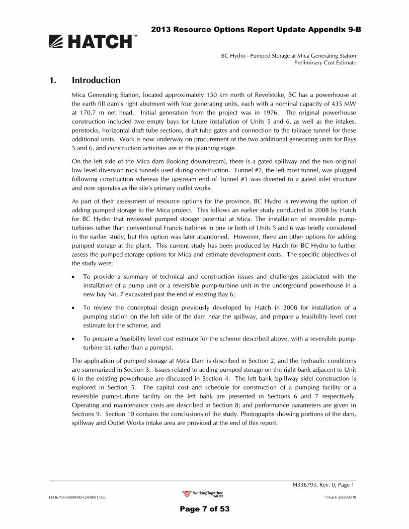
1. Introduction Mica Generating Station, located approximately 150 km north of Revelstoke, BC has a powerhouse at the earth fill dam’s right abutment with four generating units, each with a nominal capacity of 435 MW at 170.7 m net head. Initial generation from the project was in 1976. The original powerhouse construction included two empty bays for future installation of Units 5 and 6, as well as the intakes, penstocks, horizontal draft tube sections, draft tube gates and connection to the tailrace tunnel for these additional units. Work is now underway on procurement of the two additional generating units for Bays 5 and 6, and construction activities are in the planning stage.
On the left side of the Mica dam (looking downstream), there is a gated spillway and the two original low level diversion rock tunnels used during construction. Tunnel #2, the left most tunnel, was plugged following construction whereas the upstream end of Tunnel #1 was diverted to a gated inlet structure and now operates as the site’s primary outlet works.
As part of their assessment of resource options for the province, BC Hydro is reviewing the option of adding pumped storage to the Mica project. This follows an earlier study conducted in 2008 by Hatch for BC Hydro that reviewed pumped storage potential at Mica. The installation of reversible pump-turbines rather than conventional Francis turbines in one or both of Units 5 and 6 was briefly considered in the earlier study, but this option was later abandoned. However, there are other options for adding pumped storage at the plant. This current study has been produced by Hatch for BC Hydro to further assess the pumped storage options for Mica and estimate development costs. The specific objectives of the study were:
• To provide a summary of technical and construction issues and challenges associated with the installation of a pump unit or a reversible pump-turbine unit in the underground powerhouse in a new bay No. 7 excavated past the end of existing Bay 6;
• To review the conceptual design previously developed by Hatch in 2008 for installation of a pumping station on the left side of the dam near the spillway, and prepare a feasibility level cost estimate for the scheme; and
• To prepare a feasibility level cost estimate for the scheme described above, with a reversible pump-turbine (s), rather than a pump(s).
The application of pumped storage at Mica Dam is described in Section 2, and the hydraulic conditions are summarized in Section 3. Issues related to adding pumped storage on the right bank adjacent to Unit 6 in the existing powerhouse are discussed in Section 4. The left bank (spillway side) construction is explored in Section 5. The capital cost and schedule for construction of a pumping facility or a reversible pump-turbine facility on the left bank are presented in Sections 6 and 7 respectively. Operating and maintenance costs are described in Section 8; and performance parameters are given in Sections 9. Section 10 contains the conclusions of the study. Photographs showing portions of the dam, spillway and Outlet Works intake area are provided at the end of this report.
2013 Resource Options Report Update Appendix 9-B
Page 7 of 53
BC Hydro - Pumped Storage at Mica Generating Station Preliminary Cost Estimate
H336793, Rev. 0, Page 2
H336793-00000-00-124-0001.Doc © Hatch 2006/03
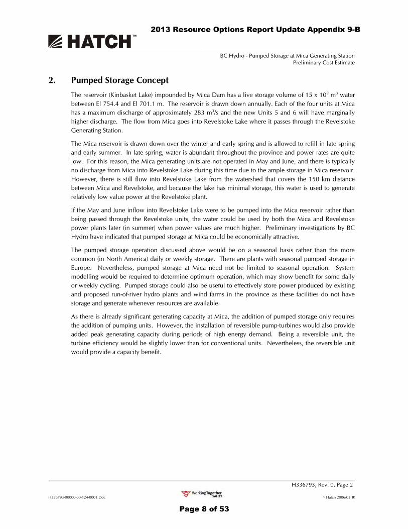
2. Pumped Storage Concept The reservoir (Kinbasket Lake) impounded by Mica Dam has a live storage volume of 15 x 109 m3 water between El 754.4 and El 701.1 m. The reservoir is drawn down annually. Each of the four units at Mica has a maximum discharge of approximately 283 m3/s and the new Units 5 and 6 will have marginally higher discharge. The flow from Mica goes into Revelstoke Lake where it passes through the Revelstoke Generating Station.
The Mica reservoir is drawn down over the winter and early spring and is allowed to refill in late spring and early summer. In late spring, water is abundant throughout the province and power rates are quite low. For this reason, the Mica generating units are not operated in May and June, and there is typically no discharge from Mica into Revelstoke Lake during this time due to the ample storage in Mica reservoir. However, there is still flow into Revelstoke Lake from the watershed that covers the 150 km distance between Mica and Revelstoke, and because the lake has minimal storage, this water is used to generate relatively low value power at the Revelstoke plant.
If the May and June inflow into Revelstoke Lake were to be pumped into the Mica reservoir rather than being passed through the Revelstoke units, the water could be used by both the Mica and Revelstoke power plants later (in summer) when power values are much higher. Preliminary investigations by BC Hydro have indicated that pumped storage at Mica could be economically attractive.
The pumped storage operation discussed above would be on a seasonal basis rather than the more common (in North America) daily or weekly storage. There are plants with seasonal pumped storage in Europe. Nevertheless, pumped storage at Mica need not be limited to seasonal operation. System modelling would be required to determine optimum operation, which may show benefit for some daily or weekly cycling. Pumped storage could also be useful to effectively store power produced by existing and proposed run-of-river hydro plants and wind farms in the province as these facilities do not have storage and generate whenever resources are available.
As there is already significant generating capacity at Mica, the addition of pumped storage only requires the addition of pumping units. However, the installation of reversible pump-turbines would also provide added peak generating capacity during periods of high energy demand. Being a reversible unit, the turbine efficiency would be slightly lower than for conventional units. Nevertheless, the reversible unit would provide a capacity benefit.
2013 Resource Options Report Update Appendix 9-B
Page 8 of 53

BC Hydro - Pumped Storage at Mica Generating Station Preliminary Cost Estimate
H336793, Rev. 0, Page 3
H336793-00000-00-124-0001.Doc © Hatch 2006/03
3. Hydraulic Conditions for Mica Pumped Storage The hydraulic conditions for the present Mica facility are as follows:
Reservoir level
• Maximum (flood) El. 757.4 m
• Maximum (normal) El. 754.4 m
• Average El. 745.2 m
• Minimum El. 707.1 m
Tailwater level
• Maximum El. 576.1 m
• Normal El. 570.6 m
• Minimum El. 567.5 m
Gross head
• Maximum 183.8 m
• Normal 174.6 m
• Minimum 136.5 m
Turbine net head
• Maximum 182.9 m
• Rated 170.7 m
Flow per generating unit
• Units 1 to 4 283 m3/s
• Units 5 & 6 300 m3/s (approximate).
During the May-June period when there would be significant pumping operations, the typical hydraulic conditions have been approximated as follows (note that these are mean values from BC Hydro’s level monitoring data for the period 2003-2008):
Reservoir level Tailwater level
• Maximum El. 750.1 m Maximum El. 574.1 m
• Average El. 732.5 m Normal El. 572.7 m
• Minimum El. 715.7 m Minimum El. 571.9 m
Gross head
• Maximum 177.0 m
• Normal 160.0 m
• Minimum 142.9 m
2013 Resource Options Report Update Appendix 9-B
Page 9 of 53

BC Hydro - Pumped Storage at Mica Generating Station Preliminary Cost Estimate
H336793, Rev. 0, Page 4
H336793-00000-00-124-0001.Doc © Hatch 2006/03
4. Pumped Storage - Extend Existing Powerhouse
4.1 General While installation of a reversible-pump turbine in Bay 5 or Bay 6 at Mica is no longer an option due to current generation expansion plans, it would still be possible to install a pumping unit, or a reversible pump-turbine unit, in an extension to the Mica powerhouse in a new Bay 7.
The maximum capacity of the unit may be dictated by shipping considerations for the pump or pump-turbine impeller/runner. A single piece impeller/runner is a definite preference. While a two piece runner is possible, costs are higher and the hydraulic design is less efficient. Site welding on a runner is possible but would result in added complexity with construction and would also increase costs, particularly for a single unit installation. Two pumping units, or two pump-turbine units could be installed if higher capacities are required.
An impeller/runner of 6.6 m (the size of the Revelstoke Unit 6 runner) or possibly more could be shipped. Using the 6.6 m runner size as a limit to pump or pump-turbine size, the preliminary unit parameters for a single unit would be as follows:
Pump Pump-Turbine
Runner diameter 6660 mm 6660 mm
Speed 171.4 rpm 171.4 rpm
Runner/impeller centerline El 541 m El 541 m
Pump mode
− Head
− Discharge
− Power
165 m
166 m3/s
295 MW
165 m
166 m3/s
295 MW
Turbine mode
− Head
− Discharge
− Power
170 m
205 m3/s
308 MW.
On a preliminary basis, the pumping unit would have the same (pump) parameters as the reversible pump-turbine, since a pump-turbine is basically designed as “a pump that also operates as a turbine”. Unlike a pump, a reversible pump-turbine has wicket gates, but when operating in the pump-mode, the gates are not used to control discharge. The gate position does vary somewhat with head, allowing slightly better efficiency at high and low heads. Otherwise, there is minimal difference in performance between a pump and a pump-turbine operating in the pump mode.
2013 Resource Options Report Update Appendix 9-B
Page 10 of 53

BC Hydro - Pumped Storage at Mica Generating Station Preliminary Cost Estimate
H336793, Rev. 0, Page 5
H336793-00000-00-124-0001.Doc © Hatch 2006/03
4.2 Pumping Unit Installation
Adding pumped storage to the Mica facility by installation of a pumping unit in a new excavation adjacent to Unit 6 has a number of attractive features including:
• By extending the present crane runway, the existing powerhouse cranes can be used for construction, installation, and ongoing maintenance activities;
• Electrical interconnection would be relatively straightforward when compared to the left-bank options. The pumping units will not operate when the Unit 6 generating unit is on line; therefore the pumping unit can utilize the Unit 6 main generator step-up transformer. The 500 kV bus and switchgear would remain unchanged;
• Electrical services can be shared with existing powerhouse electrical services;
• Pump starting using either Unit 5 or Unit 6 in a “back-to-back” starting configuration, with interconnection at generator voltage levels, should be possible;
• Mechanical services can be shared with existing powerhouse mechanical services;
• The pump discharge conduit could be connected via a Y-branch to the Unit 6 penstock; therefore only a short length of high pressure conduit would be required; and
• The pump intake may utilize the No. 2 tailrace tunnel as the intake conduit, although the existing tailrace channel may have to be excavated deeper to allow pumping operation at the lower tailwater levels.
Nevertheless, the scheme has a number of disadvantages such as:
• A significant amount of new excavation in close proximity to existing operating units would be required. Excavation quantity could be about 50,000 m3. Removal of this amount or rock by mechanical means is likely impractical, and careful, controlled blasting would be necessary for much of the rock. Removal of the rock by transport over the operating units would be an issue, and while not impractical, has a number of obvious concerns. Overall, excavation costs would be very high. This is the major drawback with this scheme;
• New excavation in the draft tube hoist chamber and manifold area would also be required for the pump suction side bulkhead gates. The existing draft tube stoplog storage area would have to be relocated;
• Concrete and new equipment for the pumping unit would have to be transported over the existing operating units. This is possible using techniques planned for the Unit 5 and 6 installation, nevertheless this does represent a project risk; and
• To avoid excessive velocity (and head loss) in the suction conduit (No 2 tailrace tunnel) pumping operations would have to be curtailed if the tailwater level drops to approximately El 571. The base of the tailrace tunnel could be excavated to allow pumping operation with lower tailwater levels but, in addition to the added cost, there would be the outage of Units 4, 5 and 6 that must be considered. A new tailrace could be constructed, again at added cost. A benefit of the new tailrace is that it could be used for rock removal during the powerhouse excavation, and possibly for the movement of construction materials and equipment into the excavation thereby limiting the movement of equipment over the existing generators to mechanical and electrical components.
2013 Resource Options Report Update Appendix 9-B
Page 11 of 53

BC Hydro - Pumped Storage at Mica Generating Station Preliminary Cost Estimate
H336793, Rev. 0, Page 6
H336793-00000-00-124-0001.Doc © Hatch 2006/03
4.3 Reversible Pump-Turbine Installation
Installation of a reversible pump-turbine unit rather than a pump adjacent to Unit 6 would increase the peak generating capacity of the Mica facility. However, there are added difficulties with the concept when compared to the pumping unit option. These issues are related primarily to the fact that the added unit must be able to operate in the generating mode in parallel with the other six units at the plant, including:
• If the pump-turbine is interconnected to the Unit 6 penstock, the penstock velocities will become very high (14 m3/s in the concrete section and 18 m3/s in the steel section - perhaps beyond precedent for a power conduit), increasing the head losses and creating waterhammer issues. The waterhammer could perhaps be mitigated with longer turbine wicket gate times, but overspeed on load rejection will increase;
• A new penstock and intake could theoretically be installed next to the Unit 6 penstock with an intake constructed behind a rock plug type cofferdam. However, the topography of the site would make the new intake very costly, if not impractical, and require underwater excavation near the existing intakes;
• As the pump-turbine unit will have to operate in generating mode in parallel with Unit 6, it can not share the Unit 6 transformer. A new transformer would be required and the transformer gallery lengthened to accommodate the new equipment. It is presumed that the 500 kV SF6 bus would have ample capacity for the added current levels with one more unit. Nevertheless, additional high voltage breakers would be required in the transformer gallery; and
• The existing tailrace tunnels are designed as free flow tunnels. With the added discharge of the additional unit, plus a small increase in maximum discharge for Units 5 and 6, which have a higher rating than the original Units 1 to 4, the tailrace tunnel hydraulic design would have to be studied, and may be marginal in size. The tunnel could be enlarged, or a second tunnel added as discussed in Section 4.2 above.
2013 Resource Options Report Update Appendix 9-B
Page 12 of 53

BC Hydro - Pumped Storage at Mica Generating Station Preliminary Cost Estimate
H336793, Rev. 0, Page 7
H336793-00000-00-124-0001.Doc © Hatch 2006/03
5. Pumped Storage on the Left Bank (Spillway Area)
5.1 Unit Size
Addition of a pumping unit or a reversible pump-turbine unit on the left side of the dam (looking downstream) allows considerable flexibility on number and size of units. Shipping limitations may influence the maximum possible unit size, but added capacity can be provided by multiple units. The most economic pumping capacity will depend on available water during the May to June time frame, and would be an economic trade-off of capital cost versus amount of energy stored.
For this preliminary study, a two unit facility with a nominal capacity of 500 MW has been selected, as agreed with BC Hydro. A single unit development would be limited to approximately 300 MW as discussed for the right side scheme in Section 4. Two units provides added capacity and the flexibility/reliability of a two unit installation. Clearly, further study would be required on number and size of units if the pumped storage scheme is potentially attractive.
The preliminary parameters for each of the two units are as follows:
Pump Pump-Turbine
Runner diameter 6105 mm 6105 mm
Speed 189.4 rpm 189.4 rpm
Runner/impeller centerline El. 539.5 m El. 539.5 m
Pump mode
− Head
− Discharge
− Power
165 m
154 m3/s
274 MW
165 m
154 m3/s
274 MW
Turbine mode
− Head
− Discharge
− Power
156 m
185 m3/s
250 MW
5.2 Facility Arrangement
Various configurations for the pumping station and pump-turbine powerhouse were considered including:
• A silo (shaft) type pumping station/powerhouse located in the spillway area;
• An underground powerhouse in the spillway area;
• An underground powerhouse located much further upstream along the diversion tunnel;
• A high pressure conduit that connects to the existing outlet works tunnel near the downstream end;
2013 Resource Options Report Update Appendix 9-B
Page 13 of 53

BC Hydro - Pumped Storage at Mica Generating Station Preliminary Cost Estimate
H336793, Rev. 0, Page 8
H336793-00000-00-124-0001.Doc © Hatch 2006/03
• A high pressure conduit that connects to the existing outlet works tunnel near the upstream end of the lower tunnel; and
• A new high pressure tunnel and intake that is separate from the existing outlet works.
The required deep submergence for the pump or pump-turbine will favour a shaft type pumping station/powerhouse or an underground pumping station/powerhouse. A shaft type pumping station was considered in the Hatch Mica 2008 study; this concept avoids the requirement for a long (700 m) access tunnel into the underground facility. However, a further assessment assuming a two-unit development indicated that the excavation volume for a shaft type powerhouse would be more than for an underground plant combined with an access tunnel. In addition, a shaft type powerhouse has added crane and elevator costs. An underground powerhouse appeared to be more attractive for this scheme, although a shaft type scheme may still be preferred for a single unit facility.
These preliminary studies have indicated that the most economical configuration for the left bank development is to use the existing Outlet Works intake structure and sloping discharge tunnel as the high pressure conduit for the pumping station or pump-turbine units. The proposed preliminary layout of this facility is shown in Figures 5.1 and 5.2. This concept requires the addition of a very large isolating gate structure to allow pressurizing the outlet tunnel. It would also necessitate the addition of a steel liner to a significant portion of the tunnel to allow the tunnel to be pressurized to reservoir level. Nevertheless, it is estimated that the cost of constructing a new intake and the additional power tunnel would increase the cost of the left bank option by about 20%. This is because the construction of the intake would be in the reservoir between the Outlet Works intake and the spillway, and much of the work would have to be completed during the normal low reservoir cycle in March and April each year. Furthermore, much of the excavation would be underwater work. By using the existing Outlet Works intake, most work would be underground, except the switchyard, draft tube, and river excavation, so construction can proceed year round.
The two diversion tunnels and the adjacent access tunnel would be used as much as possible to eliminate large quantities of underground excavation.
Using the 30 foot diameter sloping Outlet Works tunnel would probably require a grouted steel liner over a portion of the tunnel since the tunnel was originally designed as a free flow tunnel rather than a pressure tunnel. The existing concrete lining would then probably not withstand the pressures, or the effects of rapid dewatering (due to significant external pressures) if the upstream gates were closed in an emergency. This adds significant cost, but the scheme is still estimated to be less expensive than excavating a new tunnel and Outlet Works intake structure.
As the Outlet Works (which includes the use of downstream portion of original Diversion Tunnel No. 1) will still be required after installation of the new pumps or pump-turbines, the concept has a lined and embedded 30 foot diameter conduit that runs a minimum distance in the existing 45 foot tunnel to a bifurcation to the new underground powerhouse and to the new gates discharge structure. For low level discharge, the pumps or pump-turbines would be stopped, the tunnel dewatered by closing the existing upstream gates, the downstream gates opened, and the existing upstream control gates used to regulate free discharge as required. After the discharge cycle is completed, the upstream gates would be closed, the downstream discharge gates closed, the penstocks filled, and the pumps or turbines started again. With a steel lined tunnel, the change from Outlet Works to pumped storage operation would take a few
2013 Resource Options Report Update Appendix 9-B
Page 14 of 53

BC Hydro - Pumped Storage at Mica Generating Station Preliminary Cost Estimate
H336793, Rev. 0, Page 9
H336793-00000-00-124-0001.Doc © Hatch 2006/03
hours, whereas without lining the tunnels, the switchover to dewater the tunnel could take about four days at a normal 2 m/hour dewatering rate for unlined tunnels.
It is estimated to be less costly to excavate a new cross tunnel from the bifurcation in Diversion Tunnel No.1 though to Diversion Tunnel No.2 and then run a free standing steel penstock in the (unused) Diversion Tunnel No.2 to where the penstock branches off to the new underground powerhouse.
If the 30 foot penstock was extended along Diversion Tunnel No.1, the penstock would have to be embedded as velocities in the tunnel would be very high during Outlet Works discharge, with potential operational difficulties if the penstock was free standing. The alternative to re-line the existing 45 foot diameter tunnel to allow use as a pressurized tunnel, would also be very costly. By placing the new discharge structure further upstream in Diversion Tunnel No.1, the large Outlet Works discharges would be diffused before entering the river downstream of Mica Dam.
The underground powerhouse chosen at this location has about 80 m of overburden since the left bank downstream of Mica Dam is very steep, thus making use of a shaft type powerhouse more expensive even though a long access tunnel is needed to get to the powerhouse. The low voltage isolated bus shaft and access tunnel would be used as exhaust vents, with supply air being drawn in through an egress stairway tunnel that is also used as a control cable gallery to the new powerhouse from the existing Mica powerhouse. The low voltage bus shaft would be used as secondary ladder egress if there was a fire in the access tunnel and/or egress stairway.
The powerhouse concept is a typical configuration, with the two runs of medium voltage (15kV) isolated phase bus routed through a vertical shaft excavated to the surface switchyard where the transformers will be located. This eliminates the use of SF6 high voltage bus (500 kV), reduces fire potential in the underground facility, but makes the switchyard larger. This arrangement is still considered less costly due to elimination of the SF6 buses, and not requiring underground excavation for the transformer bay.
The conceptual powerhouse has the draft tube bulkhead gates adjacent to Diversion Tunnel No.2 discharge works with access to the gate structure via the upgraded construction road on the left bank. The switchyard would also be accessed by upgrading the existing road to the higher level on the left bank.
As the discharge structures on the left bank were designed for free discharge, the outlet structure for the new powerhouse tailrace needs to be excavated about 5 m deeper, and the raised rock structure has to be excavated about 11 m deeper to get adequate depth to get the water back to the powerhouse for pumping. These depths are estimated assuming the river is maintained near the Revelstoke maximum forebay elevation, or else these areas, and a portion of the river downstream of the dam would have to be dredged. Note that if the river level drops to the minimum tailwater level at Mica, which is about 6 m below Revelstoke maximum FBE, the discharge works and river would have to excavated about 6 m deeper, requiring significant additional costs for this in-river excavation.
5.3 Electrical Interconnection
The proposed electrical connection for the above left bank 2-250 MW pump turbine is shown in Figures 5.3 and 5.4. The two 250 MW (277.77 MVA) generators will each be connected to a generator switchgear assembly with a run of 15kV isolated phase bus. The generator switchgear assembly will consist of a generator circuit breaker module and a switching module that will allow the phase reversal
2013 Resource Options Report Update Appendix 9-B
Page 15 of 53

BC Hydro - Pumped Storage at Mica Generating Station Preliminary Cost Estimate
H336793, Rev. 0, Page 10
H336793-00000-00-124-0001.Doc © Hatch 2006/03
switching that is required to switch the unit between the pump and turbine modes. The switchgear assembly will also include the generator surge arrestor and capacitors as well as safety grounding switches.
Starting of the units in turbine mode will be by a static frequency converter (SFC). A single SFC will be provided for both units and be switchable between the units. The SFC will be connected to the generator switchgear with an isolated phase bus tap and associated disconnect switch on either side of the generator breaker. A station service feed will share the isolated phase bus tap with the SFC on the line side of the generator breaker on each of the generator switchgear assemblies. It is assumed that current limiting reactors will be used to reduce the rating requirements for the station service and SFC switchgear.
The generator switchgear will be connected to the 13.8-500kV generator step-up (GSU) transformers located in the surface substation via two runs of 15kV isolated phase bus installed in a vertical shaft connecting the underground powerhouse to the surface switchyard. Each GSU transformer will be connected to the 500kV overhead transmission line via a 500kV dead tank circuit breaker and associated 500kV disconnect switch. There will be a single 500kV transmission line interconnecting the new surface switchyard to the existing 500kV substation building on the right bank of the dam.
2013 Resource Options Report Update Appendix 9-B
Page 16 of 53

BC Hydro - Pumped Storage at Mica Generating Station Preliminary Cost Estimate
H336793, Rev. 0, Page 11
H336793-00000-00-124-0001.Doc © Hatch 2006/03
6. Capital Cost
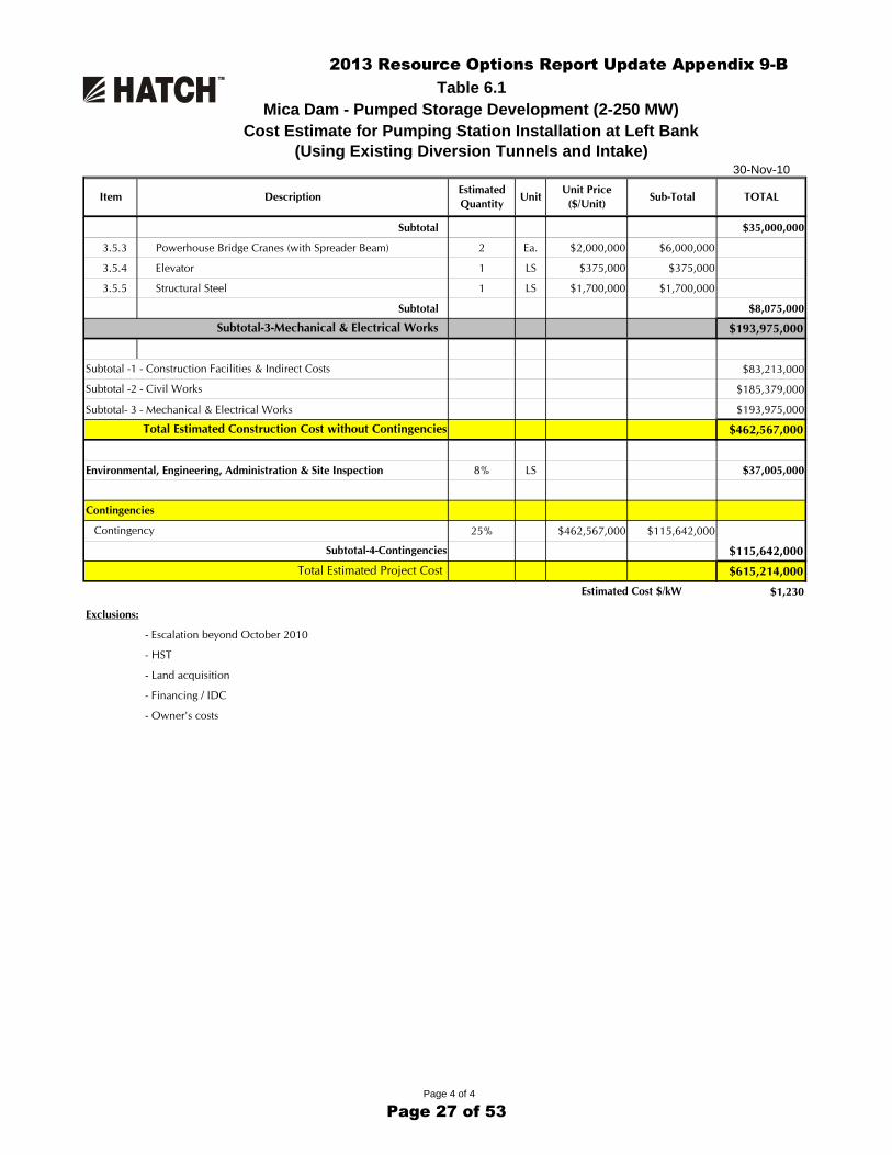
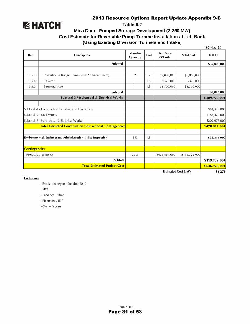
The estimated capital cost of the pumping unit facility and reversible pump-turbine plant using the existing diversion tunnels and intakes are summarised in Tables 6.1 and 6.2. The base estimates are based on single speed pumping units and single speed reversible pump-turbine units, but estimated totals have also been included to allow for facilities with variable speed motors and motor-generators. The estimated total capital costs in 2010 Canadian dollars are as follows:
Pumping Station Reversible Pump-Turbine
Powerhouse
Single speed units $ 615,000,000 $ 637,000,000
Variable speed units $ 637,000,000 $ 669,000,000
The basis for the cost estimates are as follows:
• Equipment pricing from other studies and projects;
• Project Contingency of 25%;
• Engineering and administration equal to 10% of the total capital cost;
• High level quantity takeoffs for excavation and construction;
• Normalized industry pricing for excavation, penstocks and concrete; and
• BC Hydro management and overhead costs are excluded.
These estimates are at an early feasibility level and should be used considering a variance of -35%/+50%.
2013 Resource Options Report Update Appendix 9-B
Page 17 of 53

BC Hydro - Pumped Storage at Mica Generating Station Preliminary Cost Estimate
H336793, Rev. 0, Page 12
H336793-00000-00-124-0001.Doc © Hatch 2006/03
7. Operating and Maintenance Cost Operating and maintenance costs for pumped storage plants in the United States was reviewed. As anticipated there is a significant variation in costs. Using average values, an estimated fixed cost of $9 per MW has been used. Variable costs per MWh of generation or pumping are quite low and are assumed to be approximately $0.90 per MWh generation energy for a pumped storage plant. Variable costs are assumed to be approximately $0.60 per MWh for pumping energy for a pumping plant. The higher variable costs for the pumped storage plant are because of the reciprocal pumping time that is required.
The resulting annual operating and maintenance costs for the Mica pumped storage facility are as follows:
Pumping Station Reversible Pump-Turbine
Powerhouse
Fixed cost $3,500,000 $3,300,000
Variable costs $0.90 per MWh $0.60 per MWh
2013 Resource Options Report Update Appendix 9-B
Page 18 of 53

BC Hydro - Pumped Storage at Mica Generating Station Preliminary Cost Estimate
H336793, Rev. 0, Page 13
H336793-00000-00-124-0001.Doc © Hatch 2006/03
8. Schedule
The preliminary schedule for the project is shown on Figure 8.1. The schedule would be approximately the same for the pumping station and the reversible pump-turbine facility. Total construction time is estimated to be 5.25 years, with critical path going through:
• Permitting;
• Engineering;
• Pumping/generating unit procurement, design; and
• Equipment installation and testing.
2013 Resource Options Report Update Appendix 9-B
Page 19 of 53

BC Hydro - Pumped Storage at Mica Generating Station Preliminary Cost Estimate
H336793, Rev. 0, Page 14
H336793-00000-00-124-0001.Doc © Hatch 2006/03
9. Performance Parameters
Performance curves form the pumping units and reversible pump-turbine units for the left bank 2-250 MW pump turbines are included in Figures 9.1 to 9.12. The performance curves are based on overall efficiency including head losses, pump and turbine efficiency, and motor and generator efficiency.
Waterway head losses (HL) are estimated to be as follows:
HL = k1 x (QT)2 + k2 x (QU)2
Where:
QT = total discharge from both operating units
Qu = discharge from one operating unit
k1 = constant
=8.5 x 10⁻⁵ (pumping)
=5.3 x 10⁻⁵ (generating)
k2 = constant
=4.0 x 10⁻⁵ (pumping)
=3.3 x 10⁻⁵ (generating)
Pump and turbine efficiency, flow and power values are estimated to be as follows:
a) Single Speed Units
Pumping
Total dynamic head (m) 145 165 180
Discharge (m3/s) 181 152 127
Efficiency (%) 92.8 94.0 92.4
Power (MW) 277 261 242
Generating at Optimum Efficiency
Net head (m) 140 155 175
- Discharge (m3/s) 158 163 173
- Efficiency (%) 92.8 93.5 94.0
- Power (MW) 201 232 279
2013 Resource Options Report Update Appendix 9-B
Page 20 of 53

BC Hydro - Pumped Storage at Mica Generating Station Preliminary Cost Estimate
H336793, Rev. 0, Page 15
H336793-00000-00-124-0001.Doc © Hatch 2006/03
a) Variable Speed Units
Pumping
Total dynamic head (m) 145 165 180
Discharge (m3/s) 150 152 162
Efficiency (%) 93.9 94.0 94
Power (MW) 227 261 304
Generating with optimum efficiency
Net head 140 155 175
- Discharge (m3/s) 163 162 162
- Efficiency (%) 93.6 94.0 94.0
- Power (MW) 209 231 261
Motor and motor-generator efficiency is estimated to be as follows:
• 250 MW 98.2%
• 200 MW 98.1%
• 150 MW 97.6%.
2013 Resource Options Report Update Appendix 9-B
Page 21 of 53

BC Hydro - Pumped Storage at Mica Generating Station Preliminary Cost Estimate
H336793, Rev. 0, Page 16
H336793-00000-00-124-0001.Doc © Hatch 2006/03
10. Conclusions The provision of pumped storage at Mica Dam is technically feasible, and this can be accomplished with the addition of pumping units or reversible pump-turbines.
The pumping units or pumping/generating units could be installed on the right side of the dam (looking downstream) in an extension to the existing powerhouse or on the left side of the dam in the spillway area. An installation in an extension to the powerhouse is technically difficult primarily because of the requirement for large amounts of rock excavation adjacent to operating units. The concept is also particularly difficult for a reversible pump-turbine unit because it must operate in parallel with the adjacent Unit 6 generating unit, and therefore will require its own penstock and intake.
There are numerous options for construction of a facility on the left side of the dam in the spillway area. For a two-250 MW unit scheme, the option that appears to have promise incorporates:
• An underground pumping station or powerhouse near the spillway;
• 700 m access tunnel to the pumping station/powerhouse;
• Surface transformers and switchyard to an overhead 500 kV transmission line to the right bank; and
• A high pressure conduit that utilises the existing Outlet Works gate structure as an upper reservoir intake/outlet.
The use of the outlet facilities for the high pressure conduit has features that add to the cost. These include a substantial downstream gate structure to allow pressurizing the outlet works, steel lining of portions of the tunnel, and providing substantial lengths of steel penstock.
A complete new high pressure tunnel and upper reservoir intake/outlet would also be possible, but was judged to be more costly due to additional excavation costs and excavation in the existing reservoir adjacent to the Outlet Works intake and the chute spillway. Should the pumped storage concept be found attractive, a more detailed further evaluation of options would be warranted.
The estimated capital cost of the facility, considering single speed motors/motor-generators, is as follows:
• Pumping units - $615 million; or
• Reversible pump-turbine units - $637 million.
Variable speed equipment would increase the above total project costs by approximately 3%, but would result in improved pump and turbine efficiency.
Operating and maintenance costs are estimated as $9 per kW and variable costs are expected to be roughly $0.90 per MWh.
2013 Resource Options Report Update Appendix 9-B
Page 22 of 53

BC Hydro - Pumped Storage at Mica Generating Station Preliminary Cost Estimate
H336793, Rev. 0, Page 17
H336793-00000-00-124-0001.Doc © Hatch 2006/03
Tables
2013 Resource Options Report Update Appendix 9-B
Page 23 of 53

30-Nov-10
1 Contractor's Construction Indirect & General Items
1.1 Mobilization and Demobilization 1 LS $7,575,000 $7,575,000
1.2 Construction Facilities, General Expenses & Site Services 48 Mo $349,500 $16,776,000
1.3 Site Supervision Work 48 Mo $490,500 $23,544,000
1.4 Site Surveys & Quality Control 48 Mo $210,450 $10,101,600
1.5 Transportation of Workers & Subsistence 1 LS $12,629,100 $12,629,100
1.6 Bonding & Insurance 1 LS $7,587,000 $7,587,000
1.5 Environmental Protection 1 LS $5,000,000 $5,000,000
$83,213,000
2 Civil Works
2.1 Preliminary Works & Site Facilities
2.1.1 Access Roads 1,500 m $250 $375,000
2.1.2 Cofferdams & Construction Roads (install & Remove) 20,000 m3 $20 $400,000
2.1.3 Equipment Building (Construction) 1,000 m2 $2,000 $2,000,000
Subtotal $2,775,000
2.2 Clearing & Fill
2.2.1 Draft Tube Gate Portals (Slope & Base Preparation) 3,600 m3 $25 $90,000
2.2.2 Random Granular Fill (*) 3,200 m3 $35 $112,000
2.2.3 Fine Granular Fill (*) 2,400 m3 $40 $96,000
Subtotal $298,000
2.3 500 kV Switchyard
2.3.1 Civil Works
2.3.1.1 Switchyard (60m x 60m excavate) 21,600 m3 $44 $950,400
2.3.1.2 Slope & Base Preparation (Switchyard) 600 m3 $40 $24,000
2.3.1.3 Foundation Preparation 150 m3 $40 $6,000
2.3.1.4 Compacted Back Fill: Ground Grid 1,800 m3 $45 $81,000
2.3.1.5 Ground Grid Conductor 1,000 m $90 $90,000
2.3.1.6 Concrete Foundations - Switchyard Equipment 200 m3 $375 $75,000
2.3.1.7 Oil Water Separator 1 LS $20,000 $20,000
2.3.1.8 Drainage Ditch 250 m $15 $3,750
2.3.1.9 Trench and Ducts 200 m $200 $40,000
2.3.1.10 Perimeter Fence 240 m $150 $36,000
2.3.1.11 Landscaping 1 LS $50,000 $50,000
2.3.2 Electrical Equipment
2.3.2.1 GSU Transformer (13.8/500kV) 3-Phase (Surface Swyd) 2 ea $4,100,000 $8,200,000
2.3.2.2 500kV Dead Tank Circuit Breaker 2 ea $765,000 $1,530,000
2.3.2.3 500kV Disconnect Switch 2 ea $175,000 $350,000
2.3.2.4 500kV CVT 3 ea $80,000 $240,000
2.3.2.5 500kV Surge Arrestors 9 ea $50,000 $450,000
2.3.2.6 500kV Buswork and Structures 1 LS $350,000 $350,000
Table 6.1Mica Dam - Pumped Storage Development (2-250 MW)
Cost Estimate for Pumping Station Installation at Left Bank(Using Existing Diversion Tunnels and Intake)
Sub-Total TOTALItem Description
Subtotal-1-Construction Indirects
Estimated Quantity
UnitUnit Price
($/Unit)
Page 1 of 4
2013 Resource Options Report Update Appendix 9-B
Page 24 of 53

30-Nov-10
Table 6.1Mica Dam - Pumped Storage Development (2-250 MW)
Cost Estimate for Pumping Station Installation at Left Bank(Using Existing Diversion Tunnels and Intake)
Sub-Total TOTALItem DescriptionEstimated Quantity
UnitUnit Price
($/Unit)
2.3.2.7 Lighting Protection 1 LS $150,000 $150,000
2.3.2.8 500kW Diesel Generator 1 LS $145,000 $145,000
2.3.2.9 Control and Protection 1 LS $540,000 $540,000
2.3.2.10 Control Building 1 LS $110,000 $110,000
Subtotal $13,441,150
2.4 500 kV Transmission Line (Single cct)
2.4.1 Dead End Structures (Steel & Foundation) 1.0 Ea $250,000 $250,000
2.4.2 Tower Structure (Steel & Foundation) 1.0 Ea $270,000 $270,000
2.4.3 Supply & Install Insulators & Hardware 800.0 cctm $200 $160,000
2.4.4 Supply & String Conductors 800.0 cctm $450 $360,000
2.4.5 Rem Existing Dead End and Connect to Overhead Lines 1.0 LS $100,000 $100,000
Subtotal $1,140,000
2.5 Excavation Underground (Incl. Rock Support)2.5.1 Div. No.1 to 2 Cross Tunnel 28'D-shape 5,200 m3 $650 $3,380,000
2.5.2 Div. No.2 to PH Tunnel 28'D-shape 7,500 m3 $650 $4,875,000
2.5.3 Powerhouse Access Tunnel 20'x20'x1800'L 20,400 m3 $650 $13,260,000
2.5.4 Discharge Gate House (48'W x25' L x60'H) 2,000 m3 $650 $1,300,000
2.5.5 Gate Access Tunnel widen to 20'Wx15H' x750'L 2,500 m3 $650 $1,625,000
2.5.6 Gate Access Tunnel 20'Wx15H' x80'L 700 m3 $650 $455,000
2.5.7 Low Voltage Bus/Vent Shaft (22' dia. x 260' high) 2,800 m3 $650 $1,820,000
2.5.8 Egress & Cable Tunnel 15'Wx15H' x300'L 1,900 m3 $650 $1,235,000
2.5.9 Powerhouse Turbines (120'L x80'W x35'D) 9,500 m3 $500 $4,750,000
2.5.10 Powerhouse (200'L x80'W x65'D) 29,400 m3 $500 $14,700,000
2.5.11 Service Bay (60'L x80'W x20'D) 2,700 m3 $500 $1,350,000
2.5.12 Draft Tubes (40'D-shape x 200' L) 18,100 m3 $650 $11,765,000
2.5.13 Draft Tube Gate Structure (15'W x100' L x90'D) 4,000 m3 $650 $2,600,000
Subtotal $63,115,000
2.6 Rock Support & Shotcrete2.6.1 Penstock Tunnel Liners 2" Thick 200 m3 $1,200 $240,000
2.6.2 Powerhouse Access Tunnel Liner 2" Thick 500 m3 $1,200 $600,000
2.6.3 Powerhouse Cavern 2" Thick 400 m3 $1,200 $480,000
2.6.4 Gate House Access Tunnel Liner 2" Thick 200 m3 $1,200 $240,000
Subtotal $1,560,000
2.7 Concrete2.7.1 Vertical Penstock 29' steel in 30' (820' L) 1,100 m3 $1,500 $1,650,000
2.7.2 Discharge Penstock Liner 30' steel in 45' (300' L) 7,500 m3 $1,500 $11,250,000
2.7.3 Penstock Liner to PH 26' steel in 28' (375' L) 900 m3 $1,500 $1,350,000
2.7.4 Cross Tunnel Liner 26' steel in 28' (260' L) 600 m3 $1,500 $900,000
2.7.5 Low Voltage Bus/Vent Shaft Liner (22' ID x 260' H x 1' thick) 500 m3 $1,500 $750,000
2.7.6 Egress/Cable Gallery Shaft Base (12'W x 300'H x 0.5' thick) 100 m3 $1,500 $150,000
2.7.7 Discharge Gate Shaft Base 1,900 m3 $1,500 $2,850,000
2.7.8 Discharge Gate House 20 m3 $1,500 $30,000
Page 2 of 4
2013 Resource Options Report Update Appendix 9-B
Page 25 of 53

30-Nov-10
Table 6.1Mica Dam - Pumped Storage Development (2-250 MW)
Cost Estimate for Pumping Station Installation at Left Bank(Using Existing Diversion Tunnels and Intake)
Sub-Total TOTALItem DescriptionEstimated Quantity
UnitUnit Price
($/Unit)
2.7.9 Draft Tube Gates 3,200 m3 $1,500 $4,800,000
2.7.10 Powerhouse Turbines (200'L x100'W x65'D x 50%) 1,800 m3 $1,500 $2,700,000
2.7.11 Powerhouse (200'L x100'W x 4' thick) 2,300 m3 $1,500 $3,450,000
2.7.12 Service Bay (100'L x100'W x2''D) 600 m3 $1,500 $900,000
Subtotal $30,780,000
2.8 Penstock Steel (supply & Installation)2.8.1 30' dia. at 2" Thick 1,319,000 kg $10 $13,190,000
2.8.2 29' dia. at 1.75" Thick 565,000 kg $10 $5,650,000
2.8.3 29' dia. at 1.38" Thick 586,000 kg $10 $5,860,000
2.8.4 29' dia. at 1.0" Thick 357,000 kg $10 $3,570,000
2.8.5 26' dia. at 2.25" Thick 1,200,000 kg $10 $12,000,000
2.8.6 26' dia. at 1.75" Thick 3,200,000 kg $10 $32,000,000
Subtotal $72,270,000
$185,379,000
3 Mechanical & Electrical Works
3.1 Intake
3.1.1 Trashracks 0 Ea. $400,000 $0
3.1.2 Intake Gates 0 LS $3,000,000 $0
3.1.3 Intake Bulkhead Gates 0 LS $1,500,000 $0
3.1.4 Intake Bulkhead Gate Crane 0 LS $1,000,000 $0
Subtotal $0
3.2 Discharge Gate House
3.2.1 Discharge Gates (with Hydraulic Cylinders) 3 Ea. $1,500,000 $4,500,000
Subtotal $4,500,000
3.3 Draft Tube Gate Structures
3.3.1 Draft Tube Gate Hoist 2 Ea. $100,000 $200,000
3.3.2 Draft Tube Bulkhead Gates 2 Ea. $400,000 $800,000
3.3.3 Tailrace Trashracks 2 Ea. $500,000 $1,000,000
Subtotal $2,000,000
3.4 Pumping Units
3.4.1 Supply Pumps and Governors 2 Ea. $21,700,000 $43,400,000
3.4.2 Supply Valves 2 Ea. $3,500,000 $7,000,000
3.4.3 Supply Motors and Exciters 2 Ea. $18,000,000 $36,000,000
3.4.4 Supply Starting equipment 1 LS $10,000,000 $10,000,000
3.4.5 Installation & Commissioning of Turbine-Generator 1 LS $23,000,000 $23,000,000
Subtotal $119,400,000
3.5 BOP Electrical & Mechanical Equipment
3.5.1 BOP Mechanical Supply, Installation & Commissioning 1 LS $25,000,000 $25,000,000
Subtotal $25,000,000
3.5.2 BOP Electrical Supply, Installation & Commissioning 1 LS $35,000,000 $35,000,000
Subtotal-2-Civil Works
Page 3 of 4
2013 Resource Options Report Update Appendix 9-B
Page 26 of 53
30-Nov-10
Table 6.1Mica Dam - Pumped Storage Development (2-250 MW)
Cost Estimate for Pumping Station Installation at Left Bank(Using Existing Diversion Tunnels and Intake)
Sub-Total TOTALItem DescriptionEstimated Quantity
UnitUnit Price
($/Unit)
Subtotal $35,000,000
3.5.3 Powerhouse Bridge Cranes (with Spreader Beam) 2 Ea. $2,000,000 $6,000,000
3.5.4 Elevator 1 LS $375,000 $375,000
3.5.5 Structural Steel 1 LS $1,700,000 $1,700,000
Subtotal $8,075,000
$193,975,000
$83,213,000
$185,379,000
Subtotal- 3 - Mechanical & Electrical Works $193,975,000
$462,567,000
Environmental, Engineering, Administration & Site Inspection 8% LS $37,005,000
25% $462,567,000 $115,642,000
$115,642,000
$615,214,000
$1,230
Exclusions:
- Escalation beyond October 2010
- HST
- Land acquisition
- Financing / IDC
- Owner's costs
Estimated Cost $/kW
Subtotal -1 - Construction Facilities & Indirect Costs
Subtotal -2 - Civil Works
Total Estimated Project Cost
Contingencies
Subtotal-4-Contingencies
Subtotal-3-Mechanical & Electrical Works
Total Estimated Construction Cost without Contingencies
Contingency
Page 4 of 4
2013 Resource Options Report Update Appendix 9-B
Page 27 of 53

30-Nov-10
1 Contractor's Construction Indirect & General Items
1.1 Mobilization and Demobilization 1 LS $7,575,000 $7,575,000
1.2 Construction Facilities, General Expenses & Site Services 48 Mo $349,500 $16,776,000
1.3 Site Supervision Work 48 Mo $490,500 $23,544,000
1.4 Site Surveys & Quality Control 48 Mo $210,450 $10,101,600
1.5 Transportation of Workers & Subsistence 1 LS $12,629,100 $12,629,100
1.6 Bonding & Insurance 1 LS $7,907,000 $7,907,000
1.5 Environmental Protection 1 LS $5,000,000 $5,000,000
$83,533,000
2 Civil Works
2.1 Preliminary Works & Site Facilities
2.1.1 Access Roads 1,500 m $250 $375,000
2.1.2 Cofferdams & Construction Roads (install & Remove) 20,000 m3 $20 $400,000
2.1.3 Equipment Building (Construction) 1,000 m2 $2,000 $2,000,000
Subtotal $2,775,000
2.2 Clearing & Fill
2.2.1 Draft Tube Gate Portals (Slope & Base Preparation) 3,600 m3 $25 $90,000
2.2.2 Random Granular Fill 3,200 m3 $35 $112,000
2.2.3 Fine Granular Fill 2,400 m3 $40 $96,000
Subtotal $298,000
2.3 500 kV Switchyard
2.3.1 Civil Works
2.3.1.1 Switchyard (60m x 60m excavate) 21,600 m3 $44 $950,400
2.3.1.2 Slope & Base Preparation (Switchyard) 600 m3 $40 $24,000
2.3.1.3 Foundation Preparation 150 m3 $40 $6,000
2.3.1.4 Compacted Back Fill: Ground Grid 1,800 m3 $45 $81,000
2.3.1.5 Ground Grid Conductor 1,000 m $90 $90,000
2.3.1.6 Concrete Foundations - Switchyard Equipment 200 m3 $375 $75,000
2.3.1.7 Oil Water Separator 1 LS $20,000 $20,000
2.3.1.8 Drainage Ditch 250 m $15 $3,750
2.3.1.9 Trench and Ducts 200 m $200 $40,000
2.3.1.10 Perimeter Fence 240 m $150 $36,000
2.3.1.11 Landscaping 1 LS $50,000 $50,000
2.3.2 Electrical Equipment
2.3.2.1 GSU Transformer (13.8/500kV) 3-Phase (Surface Swyd) 2 ea $4,100,000 $8,200,000
2.3.2.2 500kV Dead Tank Circuit Breaker 2 ea $765,000 $1,530,000
2.3.2.3 500kV Disconnect Switch 2 ea $175,000 $350,000
2.3.2.4 500kV CVT 3 ea $80,000 $240,000
2.3.2.5 500kV Surge Arrestors 9 ea $50,000 $450,000
2.3.2.6 500kV Buswork and Structures 1 LS $350,000 $350,000
Item Description
Subtotal-1-Construction Indirects
Estimated Quantity
UnitUnit Price
($/Unit)
Table 6.2Mica Dam - Pumped Storage Development (2-250 MW)
Cost Estimate for Reversible Pump Turbine Installation at Left Bank(Using Existing Diversion Tunnels and Intake)
Sub-Total TOTAL
Page 1 of 4
2013 Resource Options Report Update Appendix 9-B
Page 28 of 53

30-Nov-10
Item DescriptionEstimated Quantity
UnitUnit Price
($/Unit)
Table 6.2Mica Dam - Pumped Storage Development (2-250 MW)
Cost Estimate for Reversible Pump Turbine Installation at Left Bank(Using Existing Diversion Tunnels and Intake)
Sub-Total TOTAL
2.3.2.7 Lighting Protection 1 LS $150,000 $150,000
2.3.2.8 500kW Diesel Generator 1 LS $145,000 $145,000
2.3.2.9 Control and Protection 1 LS $540,000 $540,000
2.3.2.10 Control Building 1 LS $110,000 $110,000
Subtotal $13,441,150
2.4 500 kV Transmission Line (Single cct)
2.4.1 Dead End Structures (Steel & Foundation) 1.0 Ea $250,000 $250,000
2.4.2 Tower Structure (Steel & Foundation) 1.0 Ea $270,000 $270,000
2.4.3 Supply & Install Insulators & Hardware 800.0 cctm $200 $160,000
2.4.4 Supply & String Conductors 800.0 cctm $450 $360,000
2.4.5 Rem Existing Dead End and Connect to Overhead Lines 1.0 LS $100,000 $100,000
Subtotal $1,140,000
2.5 Excavation Underground (Incl. Rock Support)2.5.1 Div. No.1 to 2 Cross Tunnel 28'D-shape 5,200 m3 $650 $3,380,000
2.5.2 Div. No.2 to PH Tunnel 28'D-shape 7,500 m3 $650 $4,875,000
2.5.3 Powerhouse Access Tunnel 20'x20'x1800'L 20,400 m3 $650 $13,260,000
2.5.4 Discharge Gate House (48'W x25' L x60'H) 2,000 m3 $650 $1,300,000
2.5.5 Gate Access Tunnel widen to 20'Wx15H' x750'L 2,500 m3 $650 $1,625,000
2.5.6 Gate Access Tunnel 20'Wx15H' x80'L 700 m3 $650 $455,000
2.5.7 Low Voltage Bus/Vent Shaft (22' dia. x 260' high) 2,800 m3 $650 $1,820,000
2.5.8 Egress & Cable Tunnel 15'Wx15H' x300'L 1,900 m3 $650 $1,235,000
2.5.9 Powerhouse Turbines (120'L x80'W x35'D) 9,500 m3 $500 $4,750,000
2.5.10 Powerhouse (200'L x80'W x65'D) 29,400 m3 $500 $14,700,000
2.5.11 Service Bay (60'L x80'W x20'D) 2,700 m3 $500 $1,350,000
2.5.12 Draft Tubes (40'D-shape x 200' L) 18,100 m3 $650 $11,765,000
2.5.13 Draft Tube Gate Structure (15'W x100' L x90'D) 4,000 m3 $650 $2,600,000
Subtotal $63,115,000
2.6 Rock Support & Shotcrete2.6.1 Penstock Tunnel Liners 2" Thick 200 m3 $1,200 $240,000
2.6.2 Powerhouse Access Tunnel Liner 2" Thick 500 m3 $1,200 $600,000
2.6.3 Powerhouse Cavern 2" Thick 400 m3 $1,200 $480,000
2.6.4 Gate House Access Tunnel Liner 2" Thick 200 m3 $1,200 $240,000
Subtotal $1,560,000
2.7 Concrete2.7.1 Vertical Penstock 29' steel in 30' (820' L) 1,100 m3 $1,500 $1,650,000
2.7.2 Discharge Penstock Liner 30' steel in 45' (300' L) 7,500 m3 $1,500 $11,250,000
2.7.3 Penstock Liner to PH 26' steel in 28' (375' L) 900 m3 $1,500 $1,350,000
2.7.4 Cross Tunnel Liner 26' steel in 28' (260' L) 600 m3 $1,500 $900,000
2.7.5 Low Voltage Bus/Vent Shaft Liner (22' ID x 260' H x 1' thick) 500 m3 $1,500 $750,000
2.7.6 Egress/Cable Gallery Shaft Base (12'W x 300'H x 0.5' thick) 100 m3 $1,500 $150,000
2.7.7 Discharge Gate Shaft Base 1,900 m3 $1,500 $2,850,000
2.7.8 Discharge Gate House 20 m3 $1,500 $30,000
Page 2 of 4
2013 Resource Options Report Update Appendix 9-B
Page 29 of 53

30-Nov-10
Item DescriptionEstimated Quantity
UnitUnit Price
($/Unit)
Table 6.2Mica Dam - Pumped Storage Development (2-250 MW)
Cost Estimate for Reversible Pump Turbine Installation at Left Bank(Using Existing Diversion Tunnels and Intake)
Sub-Total TOTAL
2.7.9 Draft Tube Gates 3,200 m3 $1,500 $4,800,000
2.7.10 Powerhouse Turbines (200'L x100'W x65'D x 50%) 1,800 m3 $1,500 $2,700,000
2.7.11 Powerhouse (200'L x100'W x 4' thick) 2,300 m3 $1,500 $3,450,000
2.7.12 Service Bay (100'L x100'W x2''D) 600 m3 $1,500 $900,000
Subtotal $30,780,000
2.8 Penstock Steel (supply & Installation)2.8.1 30' dia. at 2" Thick 1,319,000 kg $10 $13,190,000
2.8.2 29' dia. at 1.75" Thick 565,000 kg $10 $5,650,000
2.8.3 29' dia. at 1.38" Thick 586,000 kg $10 $5,860,000
2.8.4 29' dia. at 1.0" Thick 357,000 kg $10 $3,570,000
2.8.5 26' dia. at 2.25" Thick 1,200,000 kg $10 $12,000,000
2.8.6 26' dia. at 1.75" Thick 3,200,000 kg $10 $32,000,000
Subtotal $72,270,000
$185,379,000
3 Mechanical & Electrical Works
3.1 Intake
3.1.1 Trashracks 1 Ea. $400,000 $400,000
3.1.2 Intake Gates 0 LS $3,000,000 $0
3.1.3 Intake Bulkhead Gates 0 LS $1,500,000 $0
3.1.4 Intake Bulkhead Gate Crane 0 LS $1,000,000 $0
Subtotal $400,000
3.2 Discharge Gate House
3.2.1 Discharge Gates (with Hydraulic Cylinders) 3 Ea. $1,500,000 $4,500,000
Subtotal $4,500,000
3.3 Draft Tube Gate Structures
3.3.1 Draft Tube Gate Hoist 2 Ea. $100,000 $200,000
3.3.2 Draft Tube Bulkhead Gates 2 Ea. $400,000 $800,000
3.3.3 Tailrace Trashracks 2 Ea. $500,000 $1,000,000
Subtotal $2,000,000
3.4 Pumping / Generating Units
3.4.1 Supply Pump-turbines and Governors 2 Ea. $29,000,000 $58,000,000
3.4.2 Supply Valves 2 Ea. $3,500,000 $7,000,000
3.4.3 Supply Motor-generators and Exciters 2 Ea. $18,500,000 $37,000,000
3.4.4 Supply Starting equipment 1 LS $10,000,000 $10,000,000
3.4.5 Installation & Commissioning of Turbine-Generator 1 LS $23,000,000 $23,000,000
Subtotal $135,000,000
3.5 BOP Electrical & Mechanical Equipment
3.5.1 BOP Mechanical Supply, Installation & Commissioning 1 LS $25,000,000 $25,000,000
Subtotal $25,000,000
3.5.2 BOP Electrical Supply, Installation & Commissioning 1 LS $35,000,000 $35,000,000
Subtotal-2-Civil Works
Page 3 of 4
2013 Resource Options Report Update Appendix 9-B
Page 30 of 53
30-Nov-10
Item DescriptionEstimated Quantity
UnitUnit Price
($/Unit)
Table 6.2Mica Dam - Pumped Storage Development (2-250 MW)
Cost Estimate for Reversible Pump Turbine Installation at Left Bank(Using Existing Diversion Tunnels and Intake)
Sub-Total TOTAL
Subtotal $35,000,000
3.5.3 Powerhouse Bridge Cranes (with Spreader Beam) 2 Ea. $2,000,000 $6,000,000
3.5.4 Elevator 1 LS $375,000 $375,000
3.5.5 Structural Steel 1 LS $1,700,000 $1,700,000
Subtotal $8,075,000
$209,975,000
$83,533,000
$185,379,000
Subtotal- 3 - Mechanical & Electrical Works $209,975,000
$478,887,000
Environmental, Engineering, Administration & Site Inspection 8% LS $38,311,000
Project Contingency 25% $478,887,000 $119,722,000
$119,722,000
$636,920,000
$1,274
Exclusions:
- Escalation beyond October 2010
- HST
- Land acquisition
- Financing / IDC
- Owner's costs
Subtotal-3-Mechanical & Electrical Works
Total Estimated Construction Cost without Contingencies
Estimated Cost $/kW
Subtotal -1 - Construction Facilities & Indirect Costs
Subtotal -2 - Civil Works
Total Estimated Project Cost
Contingencies
Subtotal
Page 4 of 4
2013 Resource Options Report Update Appendix 9-B
Page 31 of 53

BC Hydro - Pumped Storage at Mica Generating Station Preliminary Cost Estimate
H336793, Rev. 0, Page 18
H336793-00000-00-124-0001.Doc © Hatch 2006/03
Figures
2013 Resource Options Report Update Appendix 9-B
Page 32 of 53
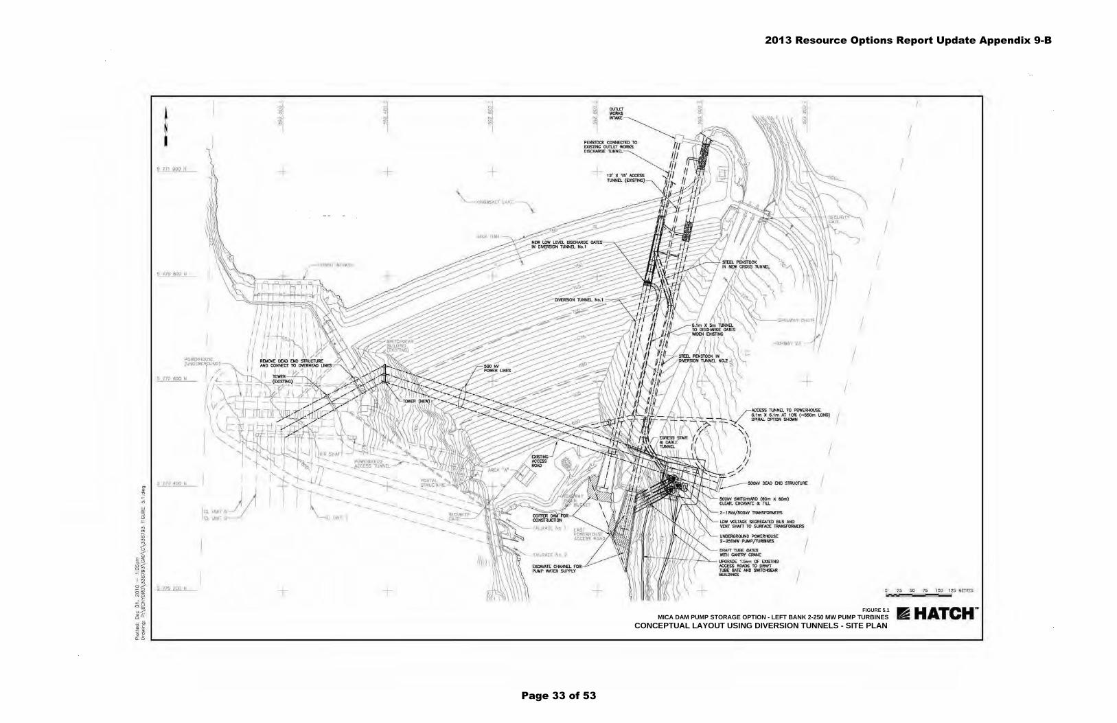
FIGURE 5.1MICA DAM PUMP STORAGE OPTION - LEFT BANK 2-250 MW PUMP TURBINES
CONCEPTUAL LAYOUT USING DIVERSION TUNNELS - SITE PLAN
I 5 771 QDO N
5 770 800 N
POWI:RHOUSE (UNDERG~DUND)
/, 5 770 600 N I L -
5 770 -400 N
5 770 200 N
u-~ -
r r
/\v/ 11 I \ \_L
"""-- ....... .......
D D D 0 0 0 N ... "' N N "' "' "' 0>
"' "' "'
+ + + "" \_______ KINBASKET LAKE
' ---~ ~~ --... POWERHOUSE ~ .,..
1___ ...__ ._tCCESS TUNNEL_...... --
........._ {; --- --1 rll· i-- -l/1 --...-_--== ~......__--... PORTAL
I --.. . -1.... ..__ --... --... ...._ ~RUCTURE
~~ ...... --... -...
I -..... -..... --... --... --- -- --- -----... .............. --... -..... ...._ -..... --... ...... ...... ...._ ........._ ......_ -..... -CL UNIT I ...... ...... ...._- --... ~~WRITY ...._
+ +
0 OU11..EI" 0
"' WORKS N
"' "' INTAKE
+ --.......
\.
+
HIGHWAY 23
0 0
"'
-f--
ACCESS TUNNEL TO POWERHOUSE 6 .1m X 6.1m AT 10X (N550m LONG) I SPIRAL OPTION SHOWN
SOOkV SWITCHYARO (60m X 60m) CLEAR. EXCAVATE ole FlU.
2-15kV/ 500kV lRANSRlRMERS
LOW VOLTAGE SEGREGATED BUS AND VENT SHAFT TO SURFACE lRANSRlRMERS
UNDERGROUND POWERHOUSE 2 - 2501otW PUMP/TURBINES
lfl))+"trtf/;;fhf..hW.-/....:::::0..__ UPGRAGE 1.5km OF EXIsnNG ACCESS ROADS TO DRAFT TUBE GATE AND SWITCHGEAR BUILDINGS
I
I
I
I
I
I
I
I
I
I
I
I
I
I
25 50 75 I 00 125 METRES
~HATCH ..
2013 Resource Options Report Update Appendix 9-B
Page 33 of 53

FIGURE 5.2MICA DAM PUMP STORAGE OPTION - LEFT BANK 2-250 MW PUMP TURBINES
CONCEPTUAL LAYOUT USING DIVERSION TUNNELS - PLAN AND SECTIONS
\~ \
30'0 VERTICAL DISCHARGE TUNNEL ABOVE
OUTLET WORKS INTAKE STRUCTURE EXISTING
CONCRETE PLUGS EXISTlNG
MICA DAM
MAXIMUM HEAD AT 25% SURGE (686') EL.2557'
30'• DISCHARGE PENSTOCK WITH 26'0 BIFURCATION
TUNNEL INVERT EL. 1B4B.04'
POWERHOUSE ACCESS TUNNEL 20' X 20' X - 1800' LONG ( 107.)
2 6'0 STEEL UNER SUPPORTED IN EXISTlNG 45' 0 D~ERSION TUNNEL
20 ' X 15' ACCESS TUNNEL TO DISCHARGE GATE HOUSE FROM EXISTING ACCESS ADir
3 DISCHARGE GATES 9' Sf'l.l1Dii-EN~ NOT SHOWN
DISCHARGE GATE HOUSE +8'X25'X60' HIGH WrTH BR lOGE CRANE.
EXJSTING ACCESS TUNNEL 12' X WIDEN TO 20' X 15'
POWERHOUSE ACCESS TUNNEL 20' X 20' X .-1800' LONG (- 1D?o)
POWERHOUSE ACCESS ROAD DOWNSTREAM DAM, EXISTING EL 1966.5'
WIDEN TO 20' X 15 '
[
ACCESS TUNNEL 12' X 15 ' E"XIST!NG
- --- - -~~~~~~~~~~~
.3 - g' X 20' DISCHARGE BULKHEAD GATES
SECTION A DIVERSION TUNNEL NO.1
26'¢ STEEL PENSTOCK (-1.75" THICK) IN EXIS11NG 4-5' 0 DIVERSION TUNNEL
SECTION B DIVERSION TUNNEL N0.2
- 1500'
LOW VOLTAGE SEGREGATED BUS AND \lENT SHAFT TO SURFACE (~22' 0)
DRAFT TlUBE GATES WITH GANTRY CRANE
EXCAVATE DISCHARGE CHUTE FOR REVERSE PUMP FLOWS
DIVERSION TUNNEL N0.2 CONCRETE PLUG
NORMAL MAX RESERVOIR EL2+75'
DISCHARGE TUNNEL INVERT EL. 1840.46'
I ~~~HARGE CHUrTE EL 1890.0' ROCK INVER"' A:JMICA TWL MAX
__1__ 863., 1'
LMICA TWL MIN EL. 1862.0'
~HATCH ..
2013 Resource Options Report Update Appendix 9-B
Page 34 of 53
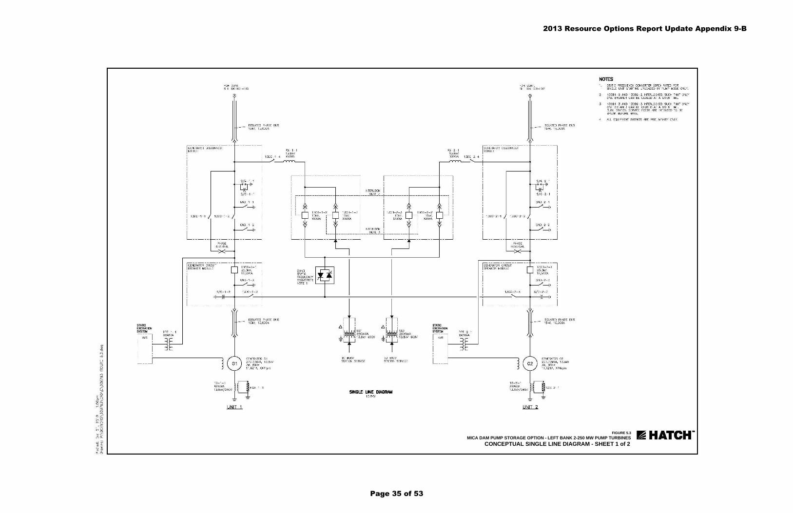
FIGURE 5.3MICA DAM PUMP STORAGE OPTION - LEFT BANK 2-250 MW PUMP TURBINES
CONCEPTUAL SINGLE LINE DIAGRAM - SHEET 1 of 2
STATIC EXCITATION SYSTEM PPT- 1- 1
l;v~ l H xxxKvA ' ' ' I I L __
FOR CONT SEE SKETCH- E02
NERATOR DISCONNECT DULE ~-----------
ISOLATED PHASE BUS 15 kV, 15,00 0A
RX-1- 1 1 3.8kV
I 13 0C- 1- 4 XXXXA
~--
' I -----------, ~-----------
' I
RX- 2 - 1 1 3.8kV XXXXA
fOR CONT. SEE SKETCH- E02
NERATOR DISCONNECT DULE ~---- -- - ----
13DC- 2- 4- I
ISOLATED PHASE BUS 15kV, 1 5,000A
-----l
I I
'
I INTERLOCK I _______ ________ _ _ _____________ I _____ ~QI!;;. _~ __ I___ ________ ___ _ ___ -------- ---- ___ -.,
i i 1 ' ' I
l JDC-1-1 I
L _____ b- -~ PHASE
REVERSAL
><
r: --- --- --- --NERATOR CIRCUIT EAKER MODULE
'
TG- 1- 1 XXXkVA 13.8kV/240 V
GENERATOR Gl 277.77MVA, 1 3 .8kV 30, SOHz 1 1 ,621A, XXXrpm
I
' I
' '
l9 L __
13CB-1-2 9 13CB- 1- 3 I I 13CB- 2 - 3 ~ 13CB- 2- 2 15kV, r-- 15kV, 15kV, - - -, 15 kV, XXXXA : XXXXA I I XXXXA : XXXXA
i ~ i INTERLOCK i ~ i I I NOTE 3 1 I L __ _ _ -------------r -----------r------------- ----~
_ __________ ___j L__ __________ _
TO 600V TO 600V STATION SERV1CE STATION SERVICE
SINGLE UNE DIAGRAM 13.8KV
~j
STATIC EXCITATION SYS'TEU PPT- 2 - 1
~;~lHxxxKvA ' ' ' I I L __
fGEN-ERATOR -ciRCUIT- - - -
I BREAKER MODULE
' ' I ' ' I '
L __________ _
l ISOLATED PHASE BUS 1 SkV, 1 S,OCOA
GENERATOR G2 277.77MVA, 13 .8kV 3~. 60Hz 11 ,6 2 1A, XXXrpm
NOTES 1. STATIC FREQUENCY CONVERTER (SFC) RATED FOR
SINGLE UNIT STARTING UNLOADED IN PUMP MODE ONLY.
2 . 13C81-2 AND 13C8 2- 2 INTERLOCKED SUCH THAT ONLY ONE BREAKER CAN BE CLOSED AT A GIVEN TIME.
3 . 13C81- 3 AND 13C82- 3 INTERLOCKED SUCH THAT ONLY ONE BREAKER CAN BE CLOSED AT A GIVEN TIME. DUAL STATION SERV1CE FEEDS ARE INTENDED TO BE BREAK BEFORE MAKE.
4. ALL EQUIPMENT RATINGS ARE PRELIMINARY ONLY.
II HATCH ..
2013 Resource Options Report Update Appendix 9-B
Page 35 of 53

FIGURE 5.4MICA DAM PUMP STORAGE OPTION - LEFT BANK 2-250 MW PUMP TURBINES
CONCEPTUAL SINGLE LINE DIAGRAM - SHEET 2 of 2
500DC-1 550kV, 1200A
500CB- 1 550kV, 2000A
>--<> o-11• S/A-1
FOR CONT. SEE SKETCH- E01
500kV OVERHEAD TIE IN TO EXISTING SWITCHGEAR BUILDING
SINGLE UNE DIAGRAM 13.8 / 500KV
50~~~~3. '; 1200A
500CB- 2 550kV, 2000A
f--o o-11• S/A- 2
i 111 11 T2
~f ~~ n~~~~ge~vA
1 ISOlATED PHASE 1 5kV, 1 5 ,OOOA
FOR CONT. SEE SKETCH- E01
NOTE 1. ALL EQUIPMENT RATINGS ARE PRELIMINARY ONLY.
BUS
r&HATCH ..
2013 Resource Options Report Update Appendix 9-B
Page 36 of 53

ID Task Name Start Finish
1 Project Start Date Jan 4 Jan 4
2 ������������ ������ ����� ������
3 ����������� ������� ��� � ��� ��
4 ����� ��� ��������� ��� � �� ��
5 ��������������������� ����� ����� ������
6 ���� ���������� ����� !������ ��� ��� � �� "�
7 #���� ����� ��������� ������ $��������� #% �� ��� ��
8 ��������� ��� ���� ������
9 !�"�#�$��%�%���"�#�&�"�' ���� (%)���
10 ��������� �& !��� ������� ��� ' ��� ""
11 !��� ������ ������ ���������()�������� ��� "� #% ��
12 $����� �*��� #% �� #% ��
13 �%�%��*$�"+"*��,�������-"������%'. (%)��� �,+��/
14 ��������� �& !��� ������� #% �� ��� "+
15 !��� ������ ������ ���������()�������� ��� ", )�� �,
16 $����� �*��� )�� �, )�� �,
17 0�*���%�,1� *�����������234��5 "�!%�� ��3�6/ �%��6�
18 ��������� �&!��� ������� ��� ", ��� -
19 !��� ������ ������ ���������()�������� ��� . )�� �,
20 $����� �*��� �� "� �� "�
21 !�7 �)"�%$�,�,�7�%�%���,���5 "����� 1��� �% (%)��� ������
22 ����/��%�� ���� �� #% �� )�� �
23 ����� ������ ����/!��%��(����/0���� )�� � ��� ��
24 1����� �& ���� � � 2*�� �3����� �� "� ��� ��
25 �����&����� ��� �,+�6� ����6�
26 �"+"*�2,�8' �,+�6� ����69
27 ��%���4���� 2� #������� 5���� )�� "� ��� "+
28 �6 ����� !���� ��� ", 2� ��
29 ��*�7��� 2���� 1�� �� � ��� .
30 PH & Service Bay Concrete Apr 29 Nov 24
31 ��� !����� ��� $������� !����� ��� ", ��� �.
32 Penstocks (Supply & Installation) Jun 18 Aug 11
33 ����7��� 0� 6���� ����� !���� ��� + �� ��
34 1��(8� 27�& ����� $�%� !���� ��� �" ��� ,
35 ���& !�%� 0� 2����� ��� + ��� "-
36 �%�:��"��*����*%���"��*�;,�8' � *�� ����6/
37 PH Crane & Hoisting Equipment Oct 14 Dec 22
38 ������ �& ����/!��%��(����/0����� 9��� #% " �� "
39 !���� $������������ ��� �. ��� ",
40 1�� ��7������ �3����� 2����� Jul 1 Jun 1
41 1�� �������� �3����� 2����� Jul 1 May 4
42 ����8���2"��:3��4�������8�����'!"''",���"�% ���66 � ���<
43 500 kV Switchyard Apr 22 Oct 644 500 kV Transmission Line Sep 9 Jun 18
45 �����������-&�"������&�"��6. ����6/ ����6�
46 Unit 1 Jan 29 Jan 2947 Unit 2 Mar 25 Mar 25
1/4
2/13
11/19
12/20
1/293/25
Environmental Notice to Proceed
Qtr 4 Qtr 1 Qtr 2 Qtr 3 Qtr 4 Qtr 1 Qtr 2 Qtr 3 Qtr 4 Qtr 1 Qtr 2 Qtr 3 Qtr 4 Qtr 1 Qtr 2 Qtr 3 Qtr 4 Qtr 1 Qtr 2 Qtr 3 Qtr 4 Qtr 1 Qtr 2 Qtr 3Year 1 Year 2 Year 3 Year 4 Year 5 Year 6
Critical Task Split Milestone Summary
Pumped Storage at Mica GS - Preliminary Project Schedule
Page 1
Project: Mica PS- Schedule-R2Date: Oct 28
Figure 8.1 Pumped Storage at Mica GS - Preliminary Project Schedule2013 Resource Options Report Update Appendix 9-B
Page 37 of 53
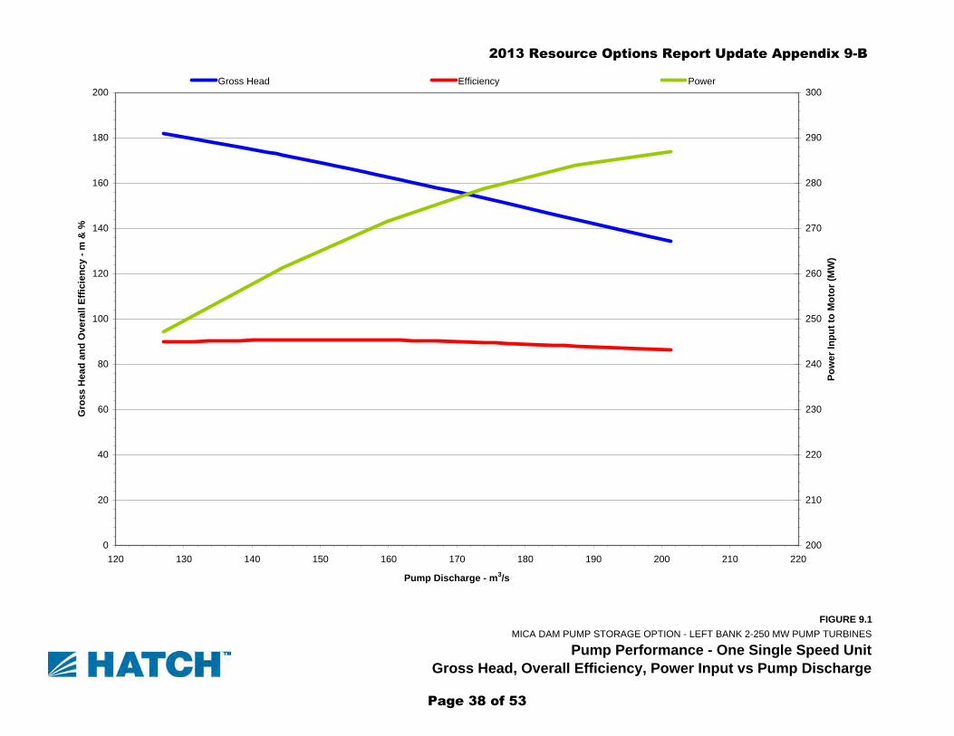
FIGURE 9.1MICA DAM PUMP STORAGE OPTION - LEFT BANK 2-250 MW PUMP TURBINES
Pump Performance - One Single Speed Unit Gross Head, Overall Efficiency, Power Input vs Pump Discharge
0
20
40
60
80
100
120
140
160
180
200
120 130 140 150 160 170 180 190 200 210 220
Pump Discharge - m3/s
Gro
ss H
ead
and
Ove
rall
Effic
ienc
y - m
& %
200
210
220
230
240
250
260
270
280
290
300
Pow
er In
put t
o M
otor
(MW
)
Gross Head Efficiency Power
2013 Resource Options Report Update Appendix 9-B
Page 38 of 53

FIGURE 9.2MICA DAM PUMP STORAGE OPTION - LEFT BANK 2-250 MW PUMP TURBINES
Generating Performance - One Single Speed Unit Overall Efficiency, Turbine Discharge vs Generator Output
60
64
68
72
76
80
84
88
92
96
40 80 120 160 200 240 280 320 360
Generator Output - MW
Ove
rall
(Gro
ss H
ead)
Effi
cien
cy -
%
80
100
120
140
160
180
200
220
240
260
Turb
ine
Dis
char
ge -
m3 /s
Res = 750 (H = 177.3) Res = 740 (H = 167.3) Res = 730 (H = 157.3) Res = 720 (H = 147.3) Res = 710 (H = 137.3)Res = 750 (H = 177.3) Res = 740 (H = 167.3) Res = 730 (H = 157.3) Res = 720 (H = 147.3) Res = 710 (H = 137.3)
2013 Resource Options Report Update Appendix 9-B
Page 39 of 53

FIGURE 9.3MICA DAM PUMP STORAGE OPTION - LEFT BANK 2-250 MW PUMP TURBINES
Generating Performance - One Single Speed Unit Max. Generator Output, Max. Turbine Discharge vs Reservoir Level
220
230
240
250
260
270
280
290
300
310
320
330
340
700 705 710 715 720 725 730 735 740 745 750 755 760
Reservoir Level - m
Max
imum
Gen
erat
or O
utpu
t - M
W
180
190
200
210
220
230
240
Max
imum
Tur
bine
Dis
char
ge -
m3 /s
Maximum Power Maximum discharge
2013 Resource Options Report Update Appendix 9-B
Page 40 of 53

FIGURE 9.4MICA DAM PUMP STORAGE OPTION - LEFT BANK 2-250 MW PUMP TURBINES
Pump Performance - One of Two Single Speed UnitsGross Head, Overall Efficiency, Power Input vs Pump Discharge
0
20
40
60
80
100
120
140
160
180
200
120 130 140 150 160 170 180 190 200 210 220
Pump Discharge - m3/s
Gro
ss H
ead
and
Ove
rall
Effic
ienc
y - m
& %
200
210
220
230
240
250
260
270
280
290
300
Pow
er In
put t
o M
otor
(MW
)
Gross Head Efficiency Power
2013 Resource Options Report Update Appendix 9-B
Page 41 of 53

FIGURE 9.5MICA DAM PUMP STORAGE OPTION - LEFT BANK 2-250 MW PUMP TURBINES
Generating Performance - One of Two Single Speed Units Overall Efficiency, Turbine Discharge vs Generator Output
60
64
68
72
76
80
84
88
92
96
40 80 120 160 200 240 280 320 360
Generator Output - MW
Ove
rall
(Gro
ss H
ead)
Effi
cien
cy -
%
80
100
120
140
160
180
200
220
240
260
Turb
ine
Dis
char
ge -
m3 /s
Res = 750 (H = 177.3) Res = 740 (H = 167.3) Res = 730 (H = 157.3) Res = 720 (H = 147.3) Res = 710 (H = 137.3)
Res = 750 (H = 177.3) Res = 740 (H = 167.3) Res = 730 (H = 157.3) Res = 720 (H = 147.3) Res = 710 (H = 137.3)
2013 Resource Options Report Update Appendix 9-B
Page 42 of 53

FIGURE 9.6MICA DAM PUMP STORAGE OPTION - LEFT BANK 2-250 MW PUMP TURBINES
Generating Performance - One of Two Single Speed UnitsMax. Generator Output, Max. Turbine Discharge vs Reservoir Level
220
230
240
250
260
270
280
290
300
310
320
330
340
700 705 710 715 720 725 730 735 740 745 750 755 760
Reservoir Level - m
Max
imum
Gen
erat
or O
utpu
t - M
W
180
190
200
210
220
230
240
Max
imum
Tur
bine
Dis
char
ge -
m3 /s
Maximum Power Maximum discharge
2013 Resource Options Report Update Appendix 9-B
Page 43 of 53

FIGURE 9.7MMICA DAM PUMP STORAGE OPTION - LEFT BANK 2-250 MW PUMP TURBINES
Pump Performance - One Variable Speed UnitGross Head, Overall Efficiency, Power Input vs Pump Discharge
60
80
100
120
140
160
180
200
220
240
260
280
120 130 140 150 160 170 180 190 200 210 220
Pump Discharge - m3/s
Gro
ss H
ead
and
Ove
rall
Effic
ienc
y - m
& %
0
40
80
120
160
200
240
280
320
360
400
440
Pow
er In
put t
o M
otor
- M
W
Gross Head +6% Speed Gross Head Gross Head -6% SpeedEfficiency +5%Speed Efficiency Effiiciency - 5%SpeedPower +5% Speed Power -5% Speed Power -5%Speed
2013 Resource Options Report Update Appendix 9-B
Page 44 of 53

FIGURE 9.8MICA DAM PUMP STORAGE OPTION - LEFT BANK 2-250 MW PUMP TURBINES
Generating Performance - One Variable Speed UnitOverall Efficiency, Turbine Discharge vs Generator Output
60
64
68
72
76
80
84
88
92
96
40 80 120 160 200 240 280 320 360
Generator Output - MW
Ove
rall
(Gro
ss H
ead)
Effi
cien
cy -
%
80
100
120
140
160
180
200
220
240
260
Turb
ine
Dis
char
ge -
m3 /s
Res = 750 (H = 177.3) Res = 740 (H = 167.3) Res = 730 (H = 157.3) Res = 720 (H = 147.3) Res = 710 (H = 137.3)Res = 750 (H = 177.3) Res = 740 (H = 167.3) Res = 730 (H = 157.3) Res = 720 (H = 147.3) Res = 710 (H = 137.3)
2013 Resource Options Report Update Appendix 9-B
Page 45 of 53
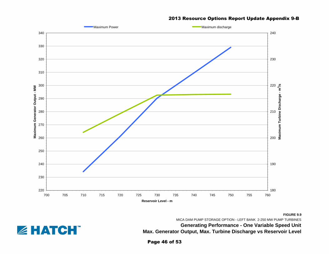
FIGURE 9.9MICA DAM PUMP STORAGE OPTION - LEFT BANK 2-250 MW PUMP TURBINES
Generating Performance - One Variable Speed UnitMax. Generator Output, Max. Turbine Discharge vs Reservoir Level
220
230
240
250
260
270
280
290
300
310
320
330
340
700 705 710 715 720 725 730 735 740 745 750 755 760
Reservoir Level - m
Max
imum
Gen
erat
or O
utpu
t - M
W
180
190
200
210
220
230
240
Max
imum
Tur
bine
Dis
char
ge -
m3 /s
Maximum Power Maximum discharge
2013 Resource Options Report Update Appendix 9-B
Page 46 of 53

FIGURE 9.10MICA DAM PUMP STORAGE OPTION - LEFT BANK 2-250 MW PUMP TURBINES
Pump Performance - One of Two Variable Speed UnitsGross Head, Overall Efficiency, Power Input vs Pump Discharge
60
80
100
120
140
160
180
200
220
240
260
280
120 130 140 150 160 170 180 190 200 210 220
Pump Discharge - m3/s
Gro
ss H
ead
and
Ove
rall
Effic
ienc
y - m
& %
0
40
80
120
160
200
240
280
320
360
400
440
Pow
er In
put t
o M
otor
- M
W
Gross Head +5% Speed Gross Head Gross Head -5% SpeedEfficiency +5%Speed Efficiency Effiiciency - 5%SpeedPower +5% Speed Power Power -5%Speed
2013 Resource Options Report Update Appendix 9-B
Page 47 of 53

FIGURE 9.11MICA DAM PUMP STORAGE OPTION - LEFT BANK 2-250 MW PUMP TURBINES
Generating Performance - One of Two Variable Speed UnitsOverall Efficiency, Turbine Discharge vs Generator Output
60
64
68
72
76
80
84
88
92
96
40 80 120 160 200 240 280 320 360
Generator Output - MW
Ove
rall
(Gro
ss H
ead)
Effi
cien
cy -
%
80
100
120
140
160
180
200
220
240
260
Turb
ine
Dis
char
ge -
m3 /s
Res = 750 (H = 177.3) Res = 740 (H = 167.3) Res = 730 (H = 157.3) Res = 720 (H = 147.3) Res = 710 (H = 137.3)
Res = 750 (H = 177.3) Res = 740 (H = 167.3) Res = 730 (H = 157.3) Res = 720 (H = 147.3) Res = 710 (H = 137.3)
2013 Resource Options Report Update Appendix 9-B
Page 48 of 53

FIGURE 9.12MICA DAM PUMP STORAGE OPTION - LEFT BANK 2-250 MW PUMP TURBINES
Generating Performance - One of Two Variable Speed UnitsMax. Generator Output, Max. Turbine Discharge vs Reservoir Level
220
230
240
250
260
270
280
290
300
310
320
330
340
700 705 710 715 720 725 730 735 740 745 750 755 760
Reservoir Level - m
Max
imum
Gen
erat
or O
utpu
t - M
W
180
190
200
210
220
230
240
Max
imum
Tur
bine
Dis
char
ge -
m3 /s
Maximum Power Maximum discharge
2013 Resource Options Report Update Appendix 9-B
Page 49 of 53

BC Hydro - Pumped Storage at Mica Generating Station Preliminary Cost Estimate
H336793, Rev. 0, Page 19
H336793-00000-00-124-0001.Doc © Hatch 2006/03
Appendix A
Photographs
2013 Resource Options Report Update Appendix 9-B
Page 50 of 53

BC Hydro - Pumped Storage at Mica Generating Station Preliminary Cost Estimate
H336793, Rev. 0, Page 20
H336793-00000-00-124-0001.Doc © Hatch 2006/03
Photo 1 Mica Dam Crest showing Outlet Works Structure Beaker
Building and Trans Lines
Photo 2 Mica Dam Left Bank, Outlet Works Discharge Chute and
Spillway
2013 Resource Options Report Update Appendix 9-B
Page 51 of 53

BC Hydro - Pumped Storage at Mica Generating Station Preliminary Cost Estimate
H336793, Rev. 0, Page 21
H336793-00000-00-124-0001.Doc © Hatch 2006/03
Photo 3 Mica Dam Left Bank Discharge Chute and Access Tunnel Portal to
Diversion Tunnels
2013 Resource Options Report Update Appendix 9-B
Page 52 of 53
Suite 400, Oceanic Plaza, 1066 West Hastings Street Vancouver, British Columbia, Canada V6E 3X2
Tel (604) 689 5767 Fax (604) 689 3918
2013 Resource Options Report Update Appendix 9-B
Page 53 of 53