Embed Size (px)
Citation preview

APPENDIX 3.8A
STRUCTURAL DESIGN SUMMARY
Rev. 0

APR1400 DCD TIER 2
i
APPENDIX 3.8A – STRUCTURAL DESIGN SUMMARY
TABLE OF CONTENTS
NUMBER TITLE PAGE
3.8A.1.1 Structural Description and Geometry ...................................................... 3.8A-1
3.8A.1.1.1 Containment Wall, Dome and Basemat ................................... 3.8A-1
3.8A.1.1.2 Containment Internal Structures ............................................... 3.8A-1
3.8A.1.1.2.1 Primary Shield Wall .......................................... 3.8A-1
3.8A.1.1.2.2 In-containment Refueling Water Storage Tank (IRWST) ................................................... 3.8A-2
3.8A.1.1.2.3 Secondary Shield Wall ...................................... 3.8A-2
3.8A.1.2 Structural Materials ................................................................................... 3.8A-2
3.8A.1.2.1 Concrete.................................................................................... 3.8A-2
3.8A.1.2.2 Liner Plate ................................................................................ 3.8A-3
3.8A.1.2.3 Reinforcing Steel ...................................................................... 3.8A-4
3.8A.1.2.4 Prestressing Steel ...................................................................... 3.8A-4
3.8A.1.3 Loads and Load Combinations .................................................................. 3.8A-5
3.8A.1.3.1 Design Loads ............................................................................ 3.8A-5
3.8A.1.3.2 Load Combinations .................................................................. 3.8A-5
3.8A.1.4 Analysis and Design for Critical Sections ................................................. 3.8A-6
3.8A.1.4.1 Containment Wall and Dome ................................................... 3.8A-6
3.8A.1.4.1.1 Description ........................................................ 3.8A-6
3.8A.1.4.1.2 Load Combinations Considered ........................ 3.8A-7
3.8A.1.4.1.3 Analysis and Design Procedures ....................... 3.8A-7
3.8A.1.4.1.3.1 General ..................................................... 3.8A-7
3.8A.1.4.1.3.2 Analysis Model ........................................ 3.8A-8
3.8A.1.4.1.3.3 Analysis Method ...................................... 3.8A-9
3.8A.1.4.1.3.4 Analysis Results ..................................... 3.8A-11
3.8A.1.4.1.3.5 Design Sections ...................................... 3.8A-11
3.8A.1.4.1.3.6 Rebar Arrangement ................................ 3.8A-12
Rev. 0
APR1400 DCD TIER 2
ii
3.8A.1.4.1.3.7 Design Results ....................................... 3.8A-12
3.8A.1.4.2 Containment Basemat............................................................. 3.8A-12
3.8A.1.4.2.1 Description ...................................................... 3.8A-12
3.8A.1.4.2.2 Load Combinations Considered ...................... 3.8A-13
3.8A.1.4.2.3 Analysis and Design Procedures ..................... 3.8A-13
3.8A.1.4.2.3.1 Design Summary .................................... 3.8A-15
3.8A.1.4.2.3.2 Stability Check ....................................... 3.8A-15
3.8A.1.4.2.3.3 Basemat Uplift Check ............................ 3.8A-16
3.8A.1.4.2.3.4 Settlement Check ................................... 3.8A-16
3.8A.1.4.2.4 Conclusion ....................................................... 3.8A-17
3.8A.1.4.3 Internal Structures .................................................................. 3.8A-17
3.8A.1.4.3.1 PSW ................................................................. 3.8A-17
3.8A.1.4.3.1.1 Description ............................................. 3.8A-17
3.8A.1.4.3.1.2 Load Combinations Considered ............. 3.8A-18
3.8A.1.4.3.1.3 Analysis Methods and Results ............... 3.8A-18
3.8A.1.4.3.1.4 Typical Rebar Arrangement ................... 3.8A-21
3.8A.1.4.3.1.5 Conclusion ............................................. 3.8A-21
3.8A.1.4.3.2 IRWST ............................................................. 3.8A-21
3.8A.1.4.3.2.1 Description ............................................. 3.8A-21
3.8A.1.4.3.2.2 Load Combinations Considered ............. 3.8A-22
3.8A.1.4.3.2.3 Analysis Methods and Results ............... 3.8A-22
3.8A.1.4.3.2.4 Conclusion ............................................. 3.8A-22
3.8A.1.4.3.3 SSW ................................................................. 3.8A-23
3.8A.1.4.3.3.1 Description ............................................. 3.8A-23
3.8A.1.4.3.3.2 Load Combinations Considered ............. 3.8A-23
3.8A.1.4.3.3.3 Analysis Methods and Results ............... 3.8A-24
3.8A.1.4.3.3.4 Typical Rebar Arrangement ................... 3.8A-24
3.8A.1.4.3.3.5 Conclusion ............................................. 3.8A-24
3.8A.2.1 Structural Description and Geometry .................................................... 3.8A-25
3.8A.2.2 Structural Materials ................................................................................. 3.8A-25
3.8A.2.3 Loads and Load Combinations ................................................................ 3.8A-26
Rev. 0

APR1400 DCD TIER 2
iii
3.8A.2.3.1 Design Loads .......................................................................... 3.8A-26
3.8A.2.3.2 Load Combinations ................................................................ 3.8A-28
3.8A.2.4 Analysis and Design for Critical Sections ............................................... 3.8A-28
3.8A.2.4.1 Basemat .................................................................................. 3.8A-29
3.8A.2.4.2 Shear walls ............................................................................. 3.8A-31
3.8A.2.4.3 Concrete Slabs ........................................................................ 3.8A-35
3.8A.3.1 Structural Description and Geometry .................................................... 3.8A-37
3.8A.3.2 Structural Materials ................................................................................. 3.8A-38
3.8A.3.3 Loads and Load Combinations ................................................................ 3.8A-38
3.8A.3.3.1 Design Loads .......................................................................... 3.8A-38 3.8A.3.3.2 Load Combinations ................................................................ 3.8A-39
3.8A.3.4 Analysis and Design for Critical Sections ............................................... 3.8A-39
3.8A.3.4.1 Basemat .................................................................................. 3.8A-40
3.8A.3.4.2 Shear walls ............................................................................. 3.8A-41
Rev. 0

APR1400 DCD TIER 2
iv
LIST OF TABLES
NUMBER TITLE PAGE
Table 3.8A-1 Allowable Stresses for Containment Materials ............................... 3.8A-43
Table 3.8A-2 Section Forces of Containment Wall Design Sections .................... 3.8A-44
Table 3.8A-3 Reinforcing Details of Containment Wall Design Sections ........... 3.8A-46
Table 3.8A-4 Rebar Stresses of RCB Wall Design Sections ................................. 3.8A-48
Table 3.8A-5 Critical Sections of RCB Basemat .................................................. 3.8A-50
Table 3.8A-6 Flexural Forces of RCB Basemat (Service load) ............................ 3.8A-51
Table 3.8A-7 Flexural Forces of RCB Basemat (Factored load) .......................... 3.8A-52
Table 3.8A-8 Shear Forces of RCB Basemat (Service load) ................................. 3.8A-53
Table 3.8A-9 Shear Forces of RCB Basemat (Factored load) ............................... 3.8A-54
Table 3.8A-10 Flexural Reinforcement Stresses of RCB Basemat ......................... 3.8A-55
Table 3.8A-11 Shear Reinforcement Stresses of RCB Basemat ............................. 3.8A-56
Table 3.8A-12 Summary of the Flexural Reinforcement of the RCB Basemat ...... 3.8A-57
Table 3.8A-13 Summary of the Shear Reinforcement of the RCB Basemat .......... 3.8A-58
Table 3.8A-14 Factor of Safety for Basemat Stability ............................................ 3.8A-59
Table 3.8A-15 Results on Factor of Safety for Basemat Stability........................... 3.8A-60
Table 3.8A-16 Uplift Area Ratios of NI Common Basemat ................................... 3.8A-61
Table 3.8A-17 Differential Settlements According to Site Profiles (Static) ........... 3.8A-62
Table 3.8A-18 Design Forces and Moments for PSW ............................................ 3.8A-63
Table 3.8A-19 Design Forces and Moments for IRWST ........................................ 3.8A-64
Table 3.8A-20 Design Forces and Moments for SSW ............................................ 3.8A-65
Table 3.8A-21 Typical Rebar Arrangement for PSW ............................................. 3.8A-66
Table 3.8A-22 Typical Rebar Arrangement for IRWST ......................................... 3.8A-67
Table 3.8A-23 Typical Rebar Arrangement for SSW ............................................. 3.8A-68
Table 3.8A-24 Enveloped Design Forces of the AB Basemat ................................ 3.8A-69
Table 3.8A-25 Required Reinforcement of the AB Basemat .................................. 3.8A-70
Table 3.8A-26 Enveloped Design Forces of the AB Shear Wall ............................ 3.8A-71
Table 3.8A-27 Required Reinforcement Summary of the AB Shear Wall ............. 3.8A-72
Table 3.8A-28 Enveloped Design Forces of the EDG Room Slab in AB ............... 3.8A-73
Rev. 0

APR1400 DCD TIER 2
v
Table 3.8A-29 Enveloped Design Forces of the SFP Slab in AB ........................... 3.8A-74
Table 3.8A-30 Enveloped Design Forces of the MSE Slab in AB .......................... 3.8A-75
Table 3.8A-31 Slab Reinforcement at Each Critical Section in AB ........................ 3.8A-76
Table 3.8A-32 Enveloped Design Forces of the EDG Building Basemat ............... 3.8A-77
Table 3.8A-33 Enveloped Design Forces of the EDG Building Shear Wall ........... 3.8A-78
Table 3.8A-34 Required Reinforcement Summary of the EDG Building Shear Wall ....................................................................................... 3.8A-79
Rev. 0
APR1400 DCD TIER 2
vi
LIST OF FIGURES
FIGURE TITLE PAGE
Figure 3.8A-1 Schematic View of Equipment Hatch and Personnel Airlocks ....... 3.8A-80
Figure 3.8A-2 FE Full Model of Containment........................................................ 3.8A-81
Figure 3.8A-3 Tendon Model Using Truss Elements ............................................. 3.8A-82
Figure 3.8A-4 FE Partial Model of Containment .................................................... 3.8A-83
Figure 3.8A-5 Input Acceleration Response Spectrum at EL. 78 -0 of RCB ........ 3.8A-84
Figure 3.8A-6 Rebar Arrangement of Wall-Basemat Junction Area ...................... 3.8A-85
Figure 3.8A-7 Rebar Arrangement of Wall Mid-height ......................................... 3.8A-86
Figure 3.8A-8 Rebar Arrangement of Polar Crane Bracket Level and Springline ........................................................................................ 3.8A-87
Figure 3.8A-9 Rebar Arrangement of Wall Around Equipment Hatch .................. 3.8A-88
Figure 3.8A-10 Rebar Arrangement of Wall Around Personnel Airlock ................. 3.8A-89
Figure 3.8A-11 NI Basemat Plan View at El. 55 -0 ................................................ 3.8A-90
Figure 3.8A-12 Full FE Model for the Basemat Structural Analysis ....................... 3.8A-91
Figure 3.8A-13 Model for AB, RCB Wall, Dome, Internal Structure and Basemat ........................................................................................... 3.8A-92
Figure 3.8A-14 LINK180 Element for Soil Spring .................................................. 3.8A-93
Figure 3.8A-15 Design Sections for Basemat Reinforcement .................................. 3.8A-94
Figure 3.8A-16 Reinforcement Arrangement of RCB Basemat (East - West View) ............................................................................................... 3.8A-95
Figure 3.8A-17 Reinforcement Arrangement of RCB Basemat (South - North View) ............................................................................................... 3.8A-96
Figure 3.8A-18 Node Location at NI basemat for Checking Settlement (Static) ..... 3.8A-97
Figure 3.8A-19 Locations of SASSI Nodes for Checking Settlement (Seismic) ..... 3.8A-98
Figure 3.8A-20 Displacements of Basemat Due to Seismic Loading (Soil #1) ........ 3.8A-99
Figure 3.8A-21 Displacements of Basemat Due to Seismic Loading (Soil #4) ...... 3.8A-100
Figure 3.8A-22 Displacements of Basemat Due to Seismic Loading (Soil #8) ...... 3.8A-101
Figure 3.8A-23 Full FE Model for the RCB Internal Structure .............................. 3.8A-102
Figure 3.8A-24 Solid, Shell, And Beam Element Model for RCB Internal Structure ........................................................................................ 3.8A-103
Figure 3.8A-25 Location of Critical Sections of the AB at EL. 100 -0 ................ 3.8A-104
Rev. 0

APR1400 DCD TIER 2
vii
Figure 3.8A-26 Location of Critical Sections of the AB at EL. 120 -0 ................ 3.8A-105
Figure 3.8A-27 Location of Critical Sections of the AB at EL. 137 -6 ................ 3.8A-106
Figure 3.8A-28 Location of Critical Sections of the AB at EL. 156 -0 ................ 3.8A-107
Figure 3.8A-29 Solid Element Model of NI Common Basemat ............................. 3.8A-108
Figure 3.8A-30 3-D View of FE Model for AB Superstructure ............................. 3.8A-109
Figure 3.8A-31 Components of FE Model For Rectangular AFW Tank in AB ..... 3.8A-110
Figure 3.8A-32 Partial FE Model for FHA Pools in AB......................................... 3.8A-111
Figure 3.8A-33 FE Model for AB Slab Design at EL. 157 -6 ............................... 3.8A-112
Figure 3.8A-34 Full FE Model for the EDG Building ............................................ 3.8A-113
Figure 3.8A-35 FE Model For the EDG Building Basemat .................................... 3.8A-114
Figure 3.8A-36 Reinforcement Arrangement of the AB Basemat .......................... 3.8A-115
Figure 3.8A-37 Typical Reinforcement of the AB Basemat (Section A) ............... 3.8A-116
Figure 3.8A-38 Typical Reinforcement of the AB Basemat (Section B) ............... 3.8A-117
Figure 3.8A-39 Typical Reinforcement Details of Basemat ................................... 3.8A-118
Figure 3.8A-40 Reinforcement Arrangement of the AB MSIV House Wall (Section 1) ..................................................................................... 3.8A-119
Figure 3.8A-41 Reinforcement Arrangement of the AB MSIV House Wall (Section 2) ..................................................................................... 3.8A-120
Figure 3.8A-42 Reinforcement Arrangement of the AB AFWST Wall ................. 3.8A-121
Figure 3.8A-43 Reinforcement Arrangement of the AB MCR Wall (Section 1) ... 3.8A-122
Figure 3.8A-44 Reinforcement Arrangement of the AB MCR Wall (Section 2) ... 3.8A-123
Figure 3.8A-45 Reinforcement Arrangement of the AB SFP Wall ........................ 3.8A-124
Figure 3.8A-46 Reinforcement Arrangement of the AB FHA Wall (Section 1) .... 3.8A-125
Figure 3.8A-47 Reinforcement Arrangement of the AB FHA Wall (Section 2) .... 3.8A-126
Figure 3.8A-48 Typical Shearwall Reinforcement Arrangement Detail ................ 3.8A-127
Figure 3.8A-49 Slab Reinforcements for the EDG Room in AB ........................... 3.8A-128
Figure 3.8A-50 Slab Reinforcements for the SFP in AB ........................................ 3.8A-129
Figure 3.8A-51 Slab Reinforcements for the MSE in AB ...................................... 3.8A-130
Figure 3.8A-52 Typical Slab Reinforcement Arrangement Detail ......................... 3.8A-131
Figure 3.8A-53 Location of Critical Sections of the EDG Building ....................... 3.8A-132
Figure 3.8A-54 Typical Reinforcement of the EDG Building Basemat ................. 3.8A-133
Figure 3.8A-55 Reinforcement Arrangement of Center Wall of the EDG Building ......................................................................................... 3.8A-134
Rev. 0

APR1400 DCD TIER 2
viii
Figure 3.8A-56 Reinforcement Arrangement of the West Wall of the EDG Building ......................................................................................... 3.8A-135
Rev. 0
APR1400 DCD TIER 2
3.8A-1
APPENDIX 3.8A – STRUCTURAL DESIGN SUMMARY
3.8A.1 Reactor Containment Building
This section provides details of the analysis and design for the critical sections relevant to containment structures: containment wall and dome, internal structures, and basemat.
3.8A.1.1 Structural Description and Geometry
3.8A.1.1.1 Containment Wall, Dome and Basemat
The containment consists of a right circular cylinder closed on top by a hemispherical dome. The cylindrical wall, dome, and internal structures are supported on a nuclear island (NI) common basemat with a central cavity and tendon gallery. The containment is constructed of concrete and prestressed by horizontal and vertical post-tensioned tendons in the wall and dome.
The basemat is constructed of conventional reinforced concrete.
An equipment hatch is provided for maintenance and removal of equipment (including the steam generators). Personnel airlocks are also provided.
The interior face of the reactor containment building is lined with 6 mm (0.25 in) thickness steel liner plate to form a leak-tight barrier and this liner plate is used as formwork during concrete placement. Thickened embedment plates and polar crane support brackets are welded into the liner plate. The basemat is lined with steel plate welded to embedded floor beams and covered by fill concrete.
3.8A.1.1.2 Containment Internal Structures
3.8A.1.1.2.1 Primary Shield Wall
The primary shield wall (PSW) is a reinforced concrete structure that houses the reactor, provides primary radiation shielding, and is an integral part of the internal structures. The PSW reinforcing is anchored into the containment basemat by the use of mechanical splices welded to both sides of a thickened liner plate. The PSW provides support for the reactor, refueling pool walls above the reactor cavity, and refueling pool slabs. The PSW forms a monolithic ring that
Rev. 0

APR1400 DCD TIER 2
3.8A-2
surrounds the reactor vessel. Penetrations in the PSW are provided for the primary loop piping and cavity ventilation system.
3.8A.1.1.2.2 In-containment Refueling Water Storage Tank (IRWST)
The in-containment refueling water storage tank (IRWST) provides storage of refueling water, a single source of water for the safety injection and containment spray pumps, and a heat sink for the safety depressurization system. The IRWST is annulus shape and uses the lower section of the internal structure as its outer boundary. The IRWST is provided with a stainless steel liner to prevent leakage. The IRWST consists of a top and bottom slab and exterior and interior walls. The bottom slab of the IRWST rests on the containment basemat and the top and bottom slab are rigidly connected to the secondary shield wall (SSW).
3.8A.1.1.2.3 Secondary Shield Wall
The SSW is a circular reinforced concrete structure that, together with the refueling pool walls, encloses the nuclear steam supply system (NSSS) equipment, except for the reactor vessel. The SSW major reinforcing, which is necessary for carrying the seismic overturning moment, is anchored into the containment basemat in a manner similar to the PSW. The SSW provides lateral support for the steam generators, reactor coolant pumps, and pressurizer and supports the operating and intermediate floors.
3.8A.1.2 Structural Materials
The principal construction materials for the reactor containment building are concrete, liner plate, reinforcing steel, and prestressing steel. The minimum specified material properties are used for the conservative design of the reactor containment building. The detailed material properties considered in the analysis and design of the reactor containment building are as follows:
3.8A.1.2.1 Concrete
The concrete used in the analysis and design of the reactor containment building is normal weight concrete.
Rev. 0

APR1400 DCD TIER 2
3.8A-3
The concrete characteristics of the containment wall, dome, and internal structures are as follows:
a. Compressive Strength: 41.4 MPa (6,000 psi) at 91 days
b. Elastic Modulus: 30,440 MPa (4,415 ksi)
c. Unit Weight: 2,400 kg/m3 (150 pcf)
d. Poisson’s Ratio: 0.17
The concrete characteristics of the containment basemat are as follows:
a. Compressive Strength: 34.5 MPa (5,000 psi) at 91 days
b. Elastic Modulus: 27,800 MPa (4,030 ksi)
c. Unit Weight: 2,400 kg/m3 (150 pcf)
d. Poisson’s Ratio: 0.17
3.8A.1.2.2 Liner Plate
The containment wall, dome, and basemat are lined with 6 mm (1/4 in) thick ASME SA-516 and ASME SA-240 steel plates welded together to make a leak-tight membrane on the inside surface of the containment.
The characteristics of the carbon steel liner plate (ASME SA-516, Grade 60) are as follows:
a. Yield Strength: 220 MPa (32 ksi)
b. Tensile Strength: 415 MPa (60 ksi)
c. Elastic Modulus: 200 GPa (29,000 ksi)
d. Poisson’s Ratio: 0.3
Rev. 0

APR1400 DCD TIER 2
3.8A-4
The characteristics of the stainless steel liner plate (ASME SA-240, Type 304) are as follows:
a. Yield Strength: 205 MPa (30 ksi)
b. Tensile Strength: 515 MPa (75 ksi)
c. Elastic Modulus: 200 GPa (29,000 ksi)
d. Poisson’s Ratio: 0.3
3.8A.1.2.3 Reinforcing Steel
The material to be used for reinforcing bars for the containment conforms to ASTM A615, Grade 60. The characteristics of the material are as follows:
a. Yield Strength: 420 MPa (60 ksi)
b. Tensile Strength: 620 MPa (90 ksi)
c. Elastic Modulus: 200 GPa (29,000 ksi)
d. Poisson’s Ratio: 0.3
3.8A.1.2.4 Prestressing Steel
The multi-strand tendons are used for the post-tensioning system of the containment wall and dome. The multi-strand system employs 15.24 mm (0.6 in) diameter, seven-wire, low-relaxation strand manufactured in accordance with ASTM A416, Grade 270.
The characteristics of the tendons are as follows:
a. Elastic Limit: 1,300 MPa (189 ksi)
b. Yield Strength: 1,675 MPa (243 ksi)
c. Ultimate Strength: 1,860 MPa (270 ksi)
Rev. 0

APR1400 DCD TIER 2
3.8A-5
d. Elastic Modulus: 193 GPa (28,000 ksi)
e. Poisson’s Ratio: 0.3
3.8A.1.3 Loads and Load Combinations
3.8A.1.3.1 Design Loads
The design loads applicable to the containment wall, dome, and basemat are in accordance with the requirements of [Article CC-3200 of ASME Section III, Division 2]*, and NRC RG 1.136. The design loads considered in the analysis and design of the containment wall, dome, and basemat are described in Subsection 3.8.1.3.2.
The design loads applicable to the containment internal structures are in accordance with the requirements of [ACI 349].* The typical design loads applicable to the containment internal structures are described in Subsection 3.8.4.3.
3.8A.1.3.2 Load Combinations
The design loads, applicable load factors, and load combinations for the analysis and design of the containment wall, dome, and basemat are in accordance with the requirements of [Article CC-3200 of ASME Section III, Division 2]*, and NRC RG 1.136. The load combinations and applicable load factors considered in the analysis and design of the containment wall, dome, and basemat are shown in Table 3.8-2 (Chapter 3).
The design loads, applicable load factors, and load combinations for the analysis and design of the containment internal structures are in accordance with the requirements of [ACI 349].* The load combinations and applicable load factors considered in the analysis and design of the containment internal structures are shown in Table 3.8-9A (Chapter 3).
Rev. 0

APR1400 DCD TIER 2
3.8A-6
3.8A.1.4 Analysis and Design for Critical Sections
3.8A.1.4.1 Containment Wall and Dome
3.8A.1.4.1.1 Description
The containment encloses the entire pressurized water reactor vessel, steam generators, reactor coolant loops, pressurizer, and portions of the auxiliary and engineered safety features systems. The containment is a prestressed concrete structure composed of a cylindrical wall with a hemispherical dome and is supported by the NI concrete common basemat. The entire inside surface of the containment, including the basemat, is lined with a steel plate to provide reasonable assurance of the leak tightness of the containment.
Access to the interior of the containment is provided through two personnel airlocks. An equipment hatch permits transfer of equipment into and out of the containment. Other major penetrations in the containment wall are those required for feedwater and main steam lines and various process pipe lines, electrical penetration assemblies, and the fuel transfer tube.
The cylindrical containment wall has a constant thickness of 1.37 m (4 ft 6 in), starting from the top of the foundation basemat to the springline. The containment wall is thickened locally around the equipment hatch, two personnel airlocks, and main steam line penetration areas to provide sufficient room for deflected prestressing tendons and additional heavy reinforcing bars. Three buttresses for anchoring of horizontal tendons are located at azimuths 90 degrees, 210 degrees, and 330 degrees and extend into the dome approximately 48 degrees above the springline. With the exception of the dome buttresses, the hemispherical dome has a constant thickness of 1.22 m (4 ft).
The cylindrical portion of the containment is prestressed by a post-tensioning system consisting of horizontal and inverted “U” vertical tendons. Each horizontal tendon is anchored at buttresses 240 degrees apart, bypassing the intermediate buttress. The dome portion of the containment is prestressed by a post-tensioning system consisting of horizontal tendons up to a 45-degree vertical angle and two groups of inverted “U” vertical tendons oriented 90 degrees to each other. The inverted “U” tendons are carried through the cylindrical wall and anchored at the tendon gallery in the common basemat.
Rev. 0

APR1400 DCD TIER 2
3.8A-7
3.8A.1.4.1.2 Load Combinations Considered
The following loading combinations are critical for the analysis and design of the containment wall and dome:
a. Test: 1.0 D + 1.0 L + 1.0 Fi + 1.0 Pt + 1.0 Tt
b. Construction: 1.0 D + 1.0 L + 1.0 Fi + 1.0 To + 1.0 W
c. Normal: 1.0 D + 1.0 L + 1.0 Fi + 1.0 To + 1.0 Pv
d. Severe: 1.0 D + 1.3 L + 1.0 Ff + 1.0 To + 1.0 W + 1.0 Pv
e. Extreme: 1.0 D + 1.0 L + 1.0 Ff + 1.0 To + 1.0 Es + 1.0 Pv
f. Abnormal: 1.0 D + 1.0 L + 1.0 Ff + 1.5Pa + 1.0 Ta
g. Abnormal/Severe: 1.0 D + 1.0 L + 1.0 Ff + 1.25Pa + 1.0 Ta + 1.25 W
h. Abnormal/Extreme: 1.0 D + 1.0 L + 1.0 Ff + 1.0 Pa + 1.0 Ta + 1.0Es + 1.0Yr
3.8A.1.4.1.3 Analysis and Design Procedures
3.8A.1.4.1.3.1 General
The containment wall and dome are analyzed for the design loads and load combinations outlined in Subsections 3.8.1.3.2 and 3.8.1.3.3. Linear elastic stress analyses are performed to investigate the structural behavior of the containment wall and dome using the general purpose structural analysis program ANSYS.
The overall analysis of the containment wall and dome for various loading combinations is performed using a three-dimensional finite element (FE) model, considering large penetrations and locally thickened sections.
In order to consider the installation and testing of the polar crane before construction of the dome part, a separate FE model consisting only of the cylindrical wall is also constructed. The
Rev. 0
APR1400 DCD TIER 2
3.8A-8
liner plate is not designed as a structural member to resist structural loads on the containment. It is, therefore, not included in the FE model.
The acceptance criteria for the design of the containment wall and dome are defined based on the requirements in [Article CC-3000 of ASME Section III, Division 2]*, and described in Subsection 3.8.1.5. Table 3.8A-1 shows the allowable stresses of concrete and reinforcing steel for service and factored loads, respectively.
3.8A.1.4.1.3.2 Analysis Model
Configuration of Containment Wall and Dome
The overall configuration of the containment wall and dome is shown in Figures 3.8-1 and 3.8-2. The representative dimensions of the containment wall and dome are as follows:
a. Inside diameter of the containment wall: 45.72 m (150.0 ft)
b. Inside height from the top of basemat to the dome apex: 76.66 m (251.5 ft)
c. Height from the top of the basemat to the springline: 53.80 m (176.5 ft)
d. Thickness of the containment wall: 1.37 m (4.5 ft)
e. Thickness of the containment dome: 1.22 m (4.0 ft)
An equipment hatch, two personnel airlocks, main steam line penetrations, and three buttresses are included in the analysis model. The locally thickened sections around the equipment hatch and personnel airlock are shown in Figure 3.8-3.
Global Model
The global model consists of solid elements for the concrete, truss elements for the tendon, and shell elements for the brackets of the polar crane. An 8-node, linear, solid element (SOLID185) in the ANSYS program is used to model the concrete part of containment wall and dome, including large thickened penetration areas and buttresses. Figure 3.8A-1 shows the schematic view of equipment hatch and personnel airlocks in the FE model. The basemat of the reactor
Rev. 0

APR1400 DCD TIER 2
3.8A-9
containment building is included partially to consider the junction behavior and anchorage of the prestressing tendon. Figure 3.8A-2 shows the overall structural analysis model with FE mesh.
The prestressing tendon is modeled using truss elements, which have an axial degree of freedom only, and is embedded in the solid element part. A two-node, linear, three-dimensional truss element (LINK180) with initial tendon stress in the ANSYS program is used to model the prestressing tendon. Figure 3.8A-3 shows the tendon model using the truss elements.
The boundary condition is applied at the bottom of the basemat and vertically cut faces inside and outside of the basemat. The cut faces are fixed both radially and circumferentially, whereas the bottom face is fixed only vertically as is common when an unimportant part is cut for removal.
Partial Model
In order to consider the situation of installation and test operation of the polar crane before the dome is constructed, the partial model without the dome is constructed. This model is made simply by removing the solid elements above the El. 254 ft 6 in in the full model. The partial model is exactly the same as the full model, except for the dome part. The boundary condition at the bottom of basemat is also the same as in the full model. Figure 3.8A-4 shows the shape of the partial model.
3.8A.1.4.1.3.3 Analysis Method
The analysis of the containment wall and dome is performed using the ANSYS program with a three-dimensional FE model. A brief description for the major loads considered in the analysis and design of the containment wall and dome are as follows:
Dead Load
The weight of concrete is automatically calculated from its mass density and gravitational acceleration by the ANSYS program. The additional weights such as those of the concrete slab, steel gratings, piping system, cable trays, heating, ventilation, and air conditioning (HVAC) systems, structural steels, and polar crane bracket are also considered dead loads.
Rev. 0

APR1400 DCD TIER 2
3.8A-10
Internal Pressure
The design basis accident (DBA) pressure of 413.7 kPa (60 psig) is applied to the inside surface of the containment wall and dome. The structural integrity test pressure is 1.15 times the design pressure. External or internal events such as containment spray actuation can induce a negative pressure on the containment. Therefore, the containment is designed for a negative pressure of 27.6 kPa (4 psig). To consider the pressure, which acts on the equipment hatch cover and attached doors in personnel airlocks, additional point loads are applied through reference nodes, which are located at the center of the penetration holes and inside surface of concrete wall. These reference nodes control and transfer the pressure loads to the surface of the corresponding cylindrical sleeve using the RBE3 command in the ANSYS program.
Prestress
The prestress is divided into two cases. The initial prestress is used for service categories to maximize the concrete compressive stress. For factored categories, the final (effective) prestress is considered to maximize the tensile stress of the reinforcing steels. The prestress losses are estimated in accordance with the guidelines specified in NRC RG 1.35.1.
It is assumed that the stresses of the vertical tendon are constant from the anchor point to the springline and from the springline to the apex of the dome. Horizontal tendons that anchor to different buttresses 240 degrees apart are spaced closely enough to offset the stress variations. Hence, the stress, which is averaged throughout the length of the horizontal tendon, is used as a representative value.
Temperature Load
The thermal effect considers temperature variations during normal operating and accident conditions combined with the worst temperature condition (summer/winter) on the outside of the containment wall and dome. During normal operation, the containment is subject to a steady-state temperature condition. The linear gradient from the steady-state heat transfer analysis is applied to the stress analysis model. The containment is subject to a rapid temperature transient in the event of a loss-of-coolant accident (LOCA). The temperature transients result in a nonlinear temperature distribution within the concrete, which comes from the results of the transient heat transfer analysis.
Rev. 0

APR1400 DCD TIER 2
3.8A-11
Seismic Load
Structural analysis for the seismic load is based on the response spectrum analysis method, which computes the maximum response of a structure from the results of a modal analysis and their combinations. For the containment wall and dome, the in-structure response spectrum at EL. 78 ft 0 in is used as a base excitation input. Figure 3.8A-5(b) shows the in-structure response spectrum of the safe-shutdown earthquake (SSE) level at El. 78 ft 0 in with 5 percent damping.
3.8A.1.4.1.3.4 Analysis Results
The section forces and moments for each element are calculated from the integration of stress resultants, which are obtained from various FE analysis results. The maximum section forces and moments for the principal design sections of the containment wall are summarized in Table 3.8A-2.
3.8A.1.4.1.3.5 Design Sections
Critical sections are those portions of the containment wall and dome that (1) perform a safety-critical function, (2) are subjected to the largest stress demands, (3) are considered to be representative of the structural design, and (4) provide reasonable assurance that the structural design is being performed in a manner consistent with the guidance in the SRP, Regulatory Guides, and other regulatory requirements.
The sections at geometric discontinuity and the expected maximum stress location are considered as critical design sections. The major design sections for the containment wall are as follows:
a. Base of containment wall (wall-basemat junction)
b. Mid-height of wall
c. Polar crane bracket level and springline
d. Thickened sections around large penetrations
Rev. 0
APR1400 DCD TIER 2
3.8A-12
1) Equipment hatch
2) Personnel airlock
3.8A.1.4.1.3.6 Rebar Arrangement
Continuous vertical and horizontal reinforcements are placed at the inside and outside faces of the containment wall. Additional reinforcing bars are provided around the large penetrations in the cylindrical wall as required. Shear ties are also provided where shear reinforcing is required.
Table 3.8A-3 summarizes the reinforcing details for the major design sections of the containment wall. Figures 3.8A-6 thru Figure 3.8A-10 show the rebar arrangement for the major design sections of the containment wall.
The containment dome is also reinforced by two-way orthogonal sets of vertical reinforcing steel and hoop reinforcing steel. The orthogonal reinforcing is the continuation of the vertical reinforcing in the containment wall. Hoop reinforcing is also provided up to 45 degrees above the springline. Radial reinforcements are provided over the entire dome to resist radial tension forces resulting from curved tendons.
3.8A.1.4.1.3.7 Design Results
The design sections of the containment wall and dome are analyzed by the computer program DARTEM to check the stresses of concrete and reinforcing steel in the concrete section. The input of DARTEM consists of section geometry, material properties, section forces and moments, and loading combinations. Table 3.8A-4 presents the rebar stresses for the major design sections of the containment wall.
3.8A.1.4.2 Containment Basemat
3.8A.1.4.2.1 Description
The NI common basemat structure of the APR1400 consists of the auxiliary building (AB) area base and reactor containment building (RCB) area base structure. The NI common basemat is a reinforced concrete mat foundation that covers an area with maximum dimensions of 106.0 m 107.6 m (348 ft 353 ft). The thickness of basemat is 10 ft (El. 45 ft 0 in through EL.
Rev. 0

APR1400 DCD TIER 2
3.8A-13
55 ft 0 in) in the AB area and variable thickness of 23 ft to 33 ft (El. 45 ft 0 in through EL. 78 ft 0 in) in the RCB area in general, except partial areas such as the tendon gallery and reactor cavity area. The top of the basemat in the RCB is at El. 78 ft 0 in, whereas the basemat is at EL. 66 ft 0 in in the reactor cavity area. The arrangements of the structure are shown in Figure 3.8A-11.
The reactor containment basemat is reinforced at the top and bottom with layers of reinforcing steel bars. The reinforcing bars are arranged in the radial and hoop directions for top layers and in the orthogonal directions for bottom layers.
3.8A.1.4.2.2 Load Combinations Considered
The following loading combinations are critical for the analysis and design of the basemat:
a. Test: 1.0D + 1.0L + 1.0Lh + 1.0F + 1.0Pt
b. Normal: 1.0D + 1.0L + 1.0Lh + 1.0F
c. Severe: 1.0D + 1.3L + 1.3Lh + 1.0F
d. Abnormal: 1.0D + 1.0L + 1.0Lh + 1.0F + 1.5Pa
e. Abnormal/Extreme: 1.0D + 1.0L + 1.0Lh + 1.0F + 1.0Pa + 1.0Yr + 1.0Es
3.8A.1.4.2.3 Analysis and Design Procedures
The design of the APR1400 adheres to a standardized design concept and can be constructed on various sites, including rock site even soil site.
Among the nine soil profiles and one fixed base condition, three profiles (Soil Profiles #1, #4, and #8) are considered. Soil Profiles #1, #4, and #8 denote weak, moderate, and strong soil properties, respectively.
Although only three soil profile (upper, medium and lower bound soil cases) are considered in the basemat structural analysis, the superstructure analysis results from enveloped seismic loading in 10 analysis cases are conservatively used in the basemat structural analysis.
Rev. 0

APR1400 DCD TIER 2
3.8A-14
Therefore, it is concluded that the basemat structural analyses of the three soil profiles cover all of the basemat analyses of the soil categories given for the APR1400.
The load combinations for the basemat structure are summarized in Section 3.8A.1.4.2.2. A total of 36 load combinations (12 combinations × 3 soil profiles) were examined for the RCB basemat structure.
The NI common basemat structure is analyzed using the ANSYS program FE computer model. The NI common basemat structure model includes the containment wall, dome, internal structures, AB, and common basemat foundation structure.
The FE model for superstructures, including the RCB wall and dome, RCB internal structure, and AB structure, are connected to the solid basemat model in order to simulate the stiffness effect of superstructures to the basemat. The FE model consists of total 317,373 nodes and 313,101 elements. Figure 3.8A-12 shows the full FE model for the basemat structural analysis. The AB structure, RCB internal structure, RCB wall and dome, and basemat structure FE models are shown in Figure 3.8A-13.
The LINK180 element in ANSYS was used as a boundary condition between the basemat structure and soil in order to consider the compressing behavior of the underlying subgrade. The compression-only option was applied to the LINK180 elements of the ANSYS connected direction with the basemat structure, and the fixed boundary condition was applied to the other end side node of LINK180 element, as shown in Figure 3.8A-14. Axial (tributary) areas of each LINK180 element were calculated by applying unit pressure to the additional modeled shell element model, which has the same geometry as the basemat model.
The dead load of the basemat structure was calculated by applying vertical acceleration to the basemat structure. In addition, the reactions calculated from the analysis results of each superstructure are applied as nodal force to the basemat structure. Buoyancy loads (Lh) due to underground water are applied to the bottom of the basemat structure. Probable maximum water level used for the buoyancy loads calculation is El. 100 ft 0 in (ground level) conservatively. For SSE loads, the enveloped seismic loading from 10 analysis cases is conservatively used in each superstructure. The reactions from these analysis results are applied as nodal force to the basemat structure using the 100-40-40 effect of the three directions of seismic motion in which one component is taken at 100 percent of its maximum value and the others are taken at 40 percent of its maximum value.
Rev. 0

APR1400 DCD TIER 2
3.8A-15
The analysis results are expressed as the normal stresses and the shear stresses of solid elements. The stresses of solid elements are filed with respect to the rectangular and cylindrical coordinate systems to fit with the arrangements of reinforcement.
To envelop the flexural and shear reinforcement for the 36 load combinations, the RCB basemat is divided into 8 design sections as represented in Table 3.8A-5. Figure 3.8A-15 shows design sections for the containment basemat.
Tables 3.8A-6 through 3.8A-9 show the calculated section forces and moments for the design. The calculated design forces and moments are used as input in the concrete section design program DARTEM for the design of flexural reinforcement and shear reinforcement. The design of the concrete sections is based on the ASME Section III, Division 2.
3.8A.1.4.2.3.1 Design Summary
The results on the design of the flexural and shear reinforcement are summarized in Tables 3.8A-10 through 3.8A-13. For the flexural reinforcement, it is confirmed that the maximum stresses of the provided reinforcement do not exceed the allowable stresses for both the service and factored load conditions. For the shear reinforcement, it is confirmed that the amounts of provided reinforcement are sufficient to meet the demands of the required reinforcement for each design section. The design envelopes the given parameters so that the design is adequate for any specific site conditions within those parameters. Figures 3.8A-16 and Figure 3.8A-17 show the rebar arrangement for the basemat of the RCB.
3.8A.1.4.2.3.2 Stability Check
The NI common basemat structure is evaluated for stability against overturning, sliding, and floatation. The calculated factors of safety against overturning, sliding, and floatation for the load combinations meet the criteria of Section II of SRP 3.8.5 as shown in Table 3.8A-14.
The sliding and overturning factors of safety are determined using load combination containing dead load (D), SSE (Es), and buoyant load at normal (He). The floatation factor of safety is determined based on dead load (D) and buoyant force at flood (Hs).
The normal design ground water elevation is El. 96 ft 8 in. The extreme ground water elevation is the same as plant grade level (El. 98 ft 8 in) considering probable maximum flood.
Rev. 0

APR1400 DCD TIER 2
3.8A-16
In the earthquake load, axial force, shear force, and moment due to horizontal and vertical excitation of the structure are obtained from seismic analysis. Since seismic load governs over wind load, stability checks are not considered under wind load. A summary of overturning, sliding, and flotation check is provided in Table 3.8A-15.
3.8A.1.4.2.3.3 Basemat Uplift Check
The ground contact uplift ratio between the basemat and soils is carried out to provide reasonable assurance that the linear soil-structure interaction (SSI) analysis remains valid. The ground contact ratio is defined as the minimum ratio of the area of the foundation in contact with the soil to the total area of the foundation. Among the results from the NI common basemat analysis, the load combination cases, which are shown, the uplift phenomenon are considered for uplift check. Table 3.8A-16 shows the uplift area ratios of NI common basemat. The APR1400 NI common basemat has an 80 percent or more contact area during basemat uplift, and it can be concluded that the contact area would be acceptable.
3.8A.1.4.2.3.4 Settlement Check
Differential settlements are divided by the differential settlement within the NI common basemat and the differential settlement between the NI basemat and the turbine generator building (TGB). For the differential settlements within the NI common basemat, the static (dead and live loads) and seismic loading cases are calculated.
Figure 3.8A-18 shows the description of the node location at the bottom of the NI common basemat for checking the settlement. The nodes within a distance of approximately 15.24 m (50 ft) are selected to check the different settlement. Table 3.8A-17 shows the differential settlements at site profiles 1, 4, and 8. The maximum differential settlements per 15.24 m (50 ft) at site profiles 1, 4, and 8 are 4.470 mm (0.176 in), 1.829 mm (0.072 in), and 0.940 mm (0.037 in), respectively.
For the differential settlements by seismic loading, the displacements of the basemat relative to the free field are calculated at the 50 nodes as shown in Figure 3.8A-19. Figures 3.8A-20 through 3.8A-22 show the Z-displacement of the basemat relative to the free field according to the site profiles. It is noted that these results are obtained from the analysis of seismic loading only (not including dead load). The maximum differential settlement by seismic loading is approximately 1.829 mm (0.072 in), which is less than 2.54 mm (0.1 in).
Rev. 0

APR1400 DCD TIER 2
3.8A-17
The maximum probable differential settlements of the APR1400 NI common basemat are 4.470 mm (0.176 in) and 2.54 mm (0.1 in) in the static and seismic loading conditions. In addition, the differential settlement between the NI and TGB basemat is checked. The maximum differential settlements corresponding to soil sites (Soil #1, Soil #4, and Soil #8) of the NI and TGB basemat are 2.46 mm (0.091 in), 6.35 mm (0.250 in), and 0.46 mm (0.018 in), respectively.
3.8A.1.4.2.4 Conclusion
The basemat concrete section strengths determined from the criteria in ASME are sufficient to resist the design basis loads. It is feasible to design and construct the structural components considered. The assumptions envelope the given parameters so that the design presented is adequate for any specific site conditions within those parameters.
3.8A.1.4.3 Internal Structures
3.8A.1.4.3.1 PSW
3.8A.1.4.3.1.1 Description
The PSW is a massive rectangular concrete structure, 18.80 m (61 ft 8 in) long by 11.43 m (37 ft 6 in) wide, with cavity depicted as follows:
a. Vertical chase, 2.03 m (6 ft 8 in) by 5.18 m (17 ft 0 in), for ICI guide tubes from the seal table at the bottom of the refueling pool, El. 130 ft 0 in, down to the bottom of the ICI tunnel at El. 69 ft 0 in.
b. Horizontal chase, 5.51 m (18 ft 3/4 in) wide 4.27 m (14 ft 0 in) high, from below the seal table to below the reactor vessel for the ICI guide tubes.
c. A cavity to enclose and support the reactor vessel from the top of the PSW at El. 130 ft 0 in to the bottom of the ICI horizontal chase.
d. Openings to allow installation and access to the main coolant loop piping from the reactor vessel to the steam generators and the reactor coolant pumps back to the reactor vessel.
Rev. 0

APR1400 DCD TIER 2
3.8A-18
e. A laydown area for the upper guide structure that is a part of the fuel handing system. This opening is 5.18 m (17 ft 0 in) by 5.16 m (16 ft 11 in) and extends from the bottom of the refueling pool down to El. 106 ft 6 3/8 in.
3.8A.1.4.3.1.2 Load Combinations Considered
The following loading combinations are critical for the analysis and design of the PSW:
a. Normal: 1.4D + 1.4Lh + 1.7L and 1.1D + 1.1Lh + 1.3L + 1.2To
b. Abnormal: 1.0D + 1.0Lh + 1.0L + 1.4Pa + 1.2Ta
c. Extreme Environmental: 1.0D + 1.0Lh + 1.0L + 1.0To + 1.0Es
d. Abnormal/Extreme: 1.0D + 1.0Lh + 1.0L + 1.0Pa + 1.0Ta + 1.0Yr + 1.0Es
3.8A.1.4.3.1.3 Analysis Methods and Results
The containment internal concrete structures are interconnected at various elevations. Significant lateral loads from the RCS supports are applied at several elevations. In order to properly account for the load distribution in structures, an overall structural model representing containment internal concrete structures is prepared. Operating concrete floor slabs are modeled to mass in the Finite Element Method (FEM) model, such as slabs between the SSWs and containment shell.
The ANSYS program is used to perform structural analysis using the containment internal structure full model. The FE model consists of a total of 50,496 nodes. The number of shell, solid, and beam elements are 5,522, 41,689, and 827, respectively. The following containment internal structures are included in the analysis model:
Solid Elements
a. PSW
b. IRWST and Fill concrete
Rev. 0

APR1400 DCD TIER 2
3.8A-19
Shell Elements
a. SSW
b. Refueling pool wall and slab
c. Pressurizer (PZR) enclosure wall and slab
d. Steam generator (SG) enclosure wall
e. Operating floor slab between SSW and refueling pool wall
Frame Elements
a. Reactor coolant pump (RCP) lateral support beam
b. Reactor coolant system (RCS) model
Figure 3.8A-23 shows the full FE model for the containment internal structure. The solid element model (PSW, IRWST, and fill concrete), shell element model (SSW), and beam element model (RCS) are shown in Figure 3.8A-24.
Structure dead load consists of self-weight for PSW, SSW, RV, additional weight of floor and equipment and dead load of RCS. Fifty percent of the weights and equipment weights on the floor between the containment shell and the SSW are assumed to be distributed to the containment shell and the SSW, respectively. The large equipment weights are applied as nodal forces at the location of equipment loads.
The live load is applied as follows:
a. Concrete slabs at El.100 ft 0 in and EL.156 ft 0 in: 1.0 ksf
b. Other slabs: 0.2 ksf
Hydrostatic loads are divided by the surface pressure loads in the refueling pool and IRWST walls and bottom slabs.
Rev. 0

APR1400 DCD TIER 2
3.8A-20
Equivalent uniform temperature gradient is input directly in the ANSYS model at the appropriate nodes. The temperature profiles during normal operating condition are more severe than those of the accident condition, thus represent the limiting temperature for all the plant conditions.
Compartment pressures on RCB internal structures are result of a pipe break inside containment. The types of compartment pressures are as follows:
a. SG compartment – feedwater economizer nozzle
b. SG compartment – feedwater downcomer nozzle
c. SG compartment – SG blowdown nozzle
d. PZR compartment – PZR spray nozzle
e. PZR compartment – POSRV nozzle
f. PZR spray valve room – PZR spray line
Branch line pipe break (BLPB) loads are dynamic reactions caused by the combined effects of branch line nozzle reactions or thrust due to pipe break, jet impingement on RCS equipment, or subcompartment pressure effects on RCS equipment. The RCS support reactions due to BLPB are applied as nodal forces at the location of supports.
The hydrodynamic pressure load, which is generated by the expulsion of air in the pilot-operated safety relief valve (POSRV) discharge, is applied to the wall and bottom slab of IRWST thru the two spargers. For the hydrodynamic pressure load, by multiplying the Dynamic Impact Factor (DIF), the maximum pressure is conservatively considered as the static load in the analysis. In addition, the normalized factor is considered for the spatial distribution due to the location of spargers.
The seismic analysis for structures is performed using response spectrum analysis. A 7 % damping ratio for reinforced concrete structures (SSE) and 3 % damping ratio for the RCS model are used. In addition, the damping ratio for water in the IRWST or refueling pool is the same as that for reinforced concrete structures: the seismic response of water is only considered
Rev. 0

APR1400 DCD TIER 2
3.8A-21
as impulsive (rigid) mode for structural analysis. Figure 3.8A-5 (a) and (c) shows the in-structure response spectrum (ISRS) of the SSE level at El. 78 ft 0 in with 3 % and 7 % damping.
Three sections are selected in the PSW as critical sections. Each section has the thinnest thickness in the direction of north, south, and east. The design forces and moments for PSW critical sections are presented in the Table 3.8A-18.
3.8A.1.4.3.1.4 Typical Rebar Arrangement
The typical rebar arrangements for PSW are presented in the Table 3.8A-21.
3.8A.1.4.3.1.5 Conclusion
The PSW concrete section strengths determined from the criteria in [ACI 349]* are sufficient to resist the design basis loads. It is feasible to design and construct the structural components that are considered. The assumptions envelop the given parameters so the design is adequate for any site-specific conditions within the parameters.
3.8A.1.4.3.2 IRWST
3.8A.1.4.3.2.1 Description
The IRWST provides storage of refueling water, a single source of water for the safety injection and containment spray pumps, and a heat sink for the safety depressurization system. The IRWST is annulus shape and utilizes the lower section of the internal structure as its outer boundary. A stainless steel liner is provided inside the IRWST.
The IRWST consists of a top and bottom slab and exterior and interior walls. The bottom slab rests on the containment basemat and the top and bottom slabs are rigidly connected to the SSW. The interior wall is the reactor containment SSW. The fill concrete portion is placed between the SSW and PSW from El. 78 ft 0 in to El. 100 ft 0 in.
The exterior wall thickness of the IRWST is 0.91 m (3 ft), same as the bottom and roof slabs. The inner radius of the exterior wall is 21.89 m (71 ft 10 in) and the outer radius of the interior wall (SSW) is 16.15 m (53 ft 0 in). The top elevation of the IRWST bottom slab is El. 81 ft 0 in.
Rev. 0
APR1400 DCD TIER 2
3.8A-22
The top elevation of the IRWST roof slab is El. 100 ft 0 in. The normal water level in the IRWST is at El. 93 ft 0 in.
3.8A.1.4.3.2.2 Load Combinations Considered
The following loading combinations are critical for the analysis and design of the IRWST wall:
a. Normal: 1.4D + 1.4Lh + 1.7L or 1.1D + 1.1Lh + 1.3L + 1.2To and 1.4D + 1.4Lh + 1.7L + 1.4Ps + 1.2To
b. Abnormal: 1.0D + 1.0Lh + 1.0L + 1.4Ps + 1.2Ta
c. Extreme Environmental: 1.0D + 1.0Lh + 1.0L + 1.0To + 1.0Es
d. Abnormal/Extreme Environmental: 1.0D + 1.0Lh + 1.0L + 1.0Ps + 1.0Ta + 1.0Es
Ps is the air clearing load, which is the hydrodynamic load generated by the expulsion of air in POSRV discharge lines during the POSRV discharge following the water clearing phenomena in the sparger.
3.8A.1.4.3.2.3 Analysis Methods and Results
The IRWST FE model is part of the containment internal structure full model. Refer to Subsection 3.8A.1.4.3.1.3. The governing load to the IRWST outer wall and upper slab is the sparger discharge load. Hydrodynamic loads occur at two sparger locations (north and west). Therefore, stresses of the portions of outer wall and upper slab are investigated and critical sections are selected where the largest stress takes place. The design forces and moments for IRWST critical sections are presented in Table 3.8A-19.
The typical rebar arrangements for the IRWST are presented in the Table 3.8A-22.
3.8A.1.4.3.2.4 Conclusion
The IRWST wall/slab concrete section strengths determined from the criteria in [ACI 349]* are sufficient to resist the design basis loads. It is feasible to design and construct the structural
Rev. 0
APR1400 DCD TIER 2
3.8A-23
components considered. The assumptions envelop the given parameters so the design is adequate for any site-specific conditions within the parameters.
3.8A.1.4.3.3 SSW
3.8A.1.4.3.3.1 Description
The SSW is a circular reinforced concrete structure that extends up to the main operating floor. The wall is anchored to the containment basemat. The wall is integrally connected to the refueling pool at the fuel transfer tube side (east) and at the regenerative heat exchanger room (west). At other points, the SSW is connected to the refueling pool through the SG and PZR enclosure walls and RCP lateral support members, which make the SSW and the internal structures almost symmetric around the east-west centerline of the containment.
In addition to enclosing the primary loop and the internal structures, the SSW provides lateral support for the SGs, RCPs, PZR, and the operating and intermediate floors inside the containment.
The major floor elevations are as follows:
a. Base Floor: El. 100 ft 0 in
b. Intermediate Floor: El. 114 ft 0 in, El. 136 ft 6 in
c. Operating Floor: El.156 ft 0 in
The major design dimensions of the secondary shield wall are as follows:
a. Wall thickness: 1.22 m (4 ft)
b. Inside radius: 14.94 m (49 ft)
c. Height of wall: 17.07 m (56 ft)
3.8A.1.4.3.3.2 Load Combinations Considered
The following loading combinations are critical for the analysis and design of the SSW:
Rev. 0

APR1400 DCD TIER 2
3.8A-24
a. Normal: 1.4D + 1.4Lh + 1.7L and 1.1D + 1.1Lh + 1.3L + 1.2To
b. Abnormal: 1.0D + 1.0Lh + 1.0L + 1.4Pa + 1.2Ta
c. Extreme Environmental: 1.0D + 1.0Lh + 1.0L + 1.0To + 1.0Es
d. Abnormal/Extreme: 1.0D + 1.0Lh + 1.0L + 1.0Pa + 1.0Ta + 1.0Yr + 1.0Es
3.8A.1.4.3.3.3 Analysis Methods and Results
The SSW FE model is a part of the containment internal structure full model. Refer to Subsection 3.8A.1.4.3.1.3. The SSWs extend from El. 100 ft 0 in up to the operating floor at El. 156 ft 0 in. The SSW from El. 100 ft 0 in to El. 114 ft 0 in is selected as critical sections because the portion of the wall includes the junction between SSW and fill concrete.
The refueling pool walls extend from the bottom of pool at El. 130 ft 0 in up to El. 156 ft 0 in. The north, south, and west wall in the whole elevation are selected as critical sections.
SG enclosure walls extend from El. 156 ft 0 in up to El. 191 ft 0 in, which is the top of wall. SG enclosure walls in the whole elevation are selected as critical sections.
PZR enclosure walls extend from El. 133 ft 4 in up to El. 200 ft 0 in which is the top of wall. PZR enclosure walls from El. 156 ft 0 in up to 191 ft 0 in are selected as critical sections since the portion of the wall supports PZR laterally. The design forces and moments for SSW critical sections are presented in the Table 3.8A-20.
3.8A.1.4.3.3.4 Typical Rebar Arrangement
The typical rebar arrangements for the SSW are presented in the Table 3.8A-23.
3.8A.1.4.3.3.5 Conclusion
The SSW concrete section strengths determined from the criteria in [ACI 349]* are sufficient to resist the design basis loads. It is feasible to design and construct the structural components considered. The assumptions envelope the given parameters so that the design presented is adequate for any specific site conditions within those parameters.
Rev. 0

APR1400 DCD TIER 2
3.8A-25
3.8A.2 Auxiliary Building
This section provides details of the analysis and design for the critical sections relevant to the auxiliary building (AB) structures: reinforced concrete shear wall, slab, concrete frame, and basemat.
3.8A.2.1 Structural Description and Geometry
The auxiliary building consists of the main control room (MCR) area, electrical and control area, main steam valve house area, chemical and volume control system (CVCS) area, emergency diesel generator (EDG) area, and fuel handling area. The building description is provided in Subsection 3.8.4.1.1.
The auxiliary building is seismic Category I reinforced concrete structures, which is composed of rectangular walls, floor slabs, concrete columns, and beams. The AB surrounds the reactor containment building (RCB) and shares a common foundation basemat with the RCB. Both the structural design and physical arrangement of the AB provide protection against both external and internal hazards.
The slabs and shear walls in the building represent the primary lateral and vertical load resisting system and are designed for both gravity and seismic-related loads. Concrete slabs at various elevations in the building distribute lateral forces (through diaphragm action) to the shear walls as in-plane loads, and resist vertical forces (self-weight and seismic forces) as out-of-plane loads.
Lateral loads are transferred down to the basemat foundation through shear walls as in-plane shear forces and moments. Vertical loads on slabs are supported either by concrete beams or walls. Those are transferred to the basemat foundation by the walls and the frames composed of concrete columns and beams.
3.8A.2.2 Structural Materials
The major materials that are used in the construction are concrete, reinforcing bars, and structural steels.
Rev. 0

APR1400 DCD TIER 2
3.8A-26
Concrete
The minimum concrete compressive strength of the AB is 34.5 MPa (5,000 psi) at 91 days. The properties of the concrete are as follows:
a. Compressive strength: 34.5 MPa (5,000 psi) at 91 days
b. Elastic Modulus: 27,800 MPa (4,030 ksi)
c. Unit weight: 2,400 kg/m3 (150 pcf)
d. Poisson’s Ratio: 0.17
Reinforcing Bars
The reinforcing bars used in the AB are in accordance with ASTM A615 Gr. 60. The properties of the reinforcing bars are as followings:
a. Yield strength: 420 MPa (60 ksi)
b. Tensile strength: 620 MPa (90 ksi)
3.8A.2.3 Loads and Load Combinations
3.8A.2.3.1 Design Loads
The followings are major design loads, which are considered in the design of the AB.
Dead Load (D)
Dead load includes the weight of structures such as slabs, roofs, decking, framing (beams, columns, bracing, and walls), and the weight of permanently attached major equipment such as tanks, machinery, and cranes. Equipment loads heavier than or equal to 44.5 kN (10 kip) are considered concentrated weights.
Rev. 0

APR1400 DCD TIER 2
3.8A-27
The attachment loads includes equipment loads lower than 10 kips such as piping, cable tray, and HVAC loads. The minimum attachment loads are as follows:
a. Concrete floors: 9.6 kN/m2 (200 psf)
b. Roof floors: 7.2 kN/m2 (150 psf)
c. Interior wall: 1.0 kN/m2 (20 psf)
d. Exterior wall: 0.5 kN/m2 (10 psf)
Live Load (L)
Live loads are conventional floor loads to account for occupancy, maintenance, equipment removal, equipment laydown, and other loads that vary in intensity. The minimum live loads are as follows:
a. Concrete floors: 9.6 kN/m2 (200 psf)
b. Roof floors: 4.8 kN/m2 (100 psf)
c. Equipment removal aisle: 23.9 kN/m2 (500 psf)
d. Seismic live load: 2.4 kN/m2 (50 psf) (considered in seismic loading combination)
In order to account for wall attachments, shear walls are designed considering a minimum out-of-plane live load of 16.6 kN/m2 (350 psf).
Soil and surcharge load (Lg), hydrostatic load (Lh) are considered as live load.
Wind Load (W)
Wind load is the equivalent static load generated by the design wind velocity and is calculated in accordance with ASCE 7. The AB is designed for a 100-year recurrence interval wind.
Rev. 0

APR1400 DCD TIER 2
3.8A-28
Safe Shutdown Earthquake Load (Es)
In the structural analysis for the AB, seismic loads are considered with the equivalent static load method involving equivalent horizontal and vertical static forces.
Accident Pressure Load (Pa)
Accident pressure is applied external or internal air, gas, or liquid pressure loads during abnormal operating conditions.
High Energy Line Break (HELB) Load (Yr, Yj, Ym, Yf)
There are several high and moderate energy pipe lines routed through the AB. During an abnormal condition at the plant, it is postulated that these lines can break at various locations. The structural loads associated with pipe breaks include pipe break reactions (Yr), jet impingement load (Yj), missile impact load (Ym), compartmental flooding load (Yf), and compartment pressure (Pa).
3.8A.2.3.2 Load Combinations
The load combinations are addressed in Subsection 3.8.4.3.6 and are used for analysis and design of the AB and associated components.
3.8A.2.4 Analysis and Design for Critical Sections
This section summarizes the analysis and design for critical sections of the AB. The critical sections are listed below. The description of critical section, analysis and design methods, and design summary are provided for each critical section. The locations of critical sections are shown in Figures 3.8A-25 through 3.8A-28 and the location of the concrete frame is shown in Figure 3.8A-53.
a. Basemat
1) AB area of the nuclear island (NI) common basemat
b. Shear walls
Rev. 0

APR1400 DCD TIER 2
3.8A-29
1) North wall of the north main steam isolation valve (MSIV) house
2) North wall of the north auxiliary feedwater storage tank (AFWST)
3) West wall of the MCR
4) West wall of the spent fuel pool (SFP)
5) East wall of the fuel handling area (FHA)
c. Slabs
1) Floor slab of the EDG Room at El. 100 ft 0 in
2) Pool bottom slab of the SFP at El. 113 ft 0 in
3) Floor slab below the Main Steam Enclosure at El. 137 ft 6 in
3.8A.2.4.1 Basemat
Description
The AB shares a common foundation basemat with the RCB. The foundation of the RCB and AB is a reinforced concrete mat structure with the maximum dimensions of 106.0 m × 107.6 m (348 ft × 353 ft). The thickness of the basemat is 3.05 m (10 ft) in the AB area. The bottom of the basemat is located at elevation 40 ft 0 in and 45 ft 0 in, below the finished grade elevation. The AB basemat is reinforced at the top and bottom with layers of reinforcing steel bars. The reinforcing bars are arranged in the orthogonal directions for top and bottom layers.
Analysis and Design Methods
The reinforced concrete common basemat is analyzed and designed for the reactions due to static, seismic, and all other significant loads at the base of the superstructures. The forces and moments of the basemat area are obtained by application of design loads to the integrated static three-dimensional finite element (FE) model. The analysis methods and procedures of the NI common basemat are described in Subsection 3.8A.1.4.2.3. Figure 3.8A-29 shows the solid element model of the basemat for the AB and RCB.
Rev. 0

APR1400 DCD TIER 2
3.8A-30
Since the rigid connection between walls and basemat is not simulated in the analysis model of the NI common basemat structure, the basemat of the AB is not subject to any moment which might occur. Therefore, the additional structural analysis is executed to obtain the magnitude of the moment transferred from walls and columns, which are subjected to lateral loads. The design forces and moments for the AB basemat are summarized in Table 3.8A-24.
The AB basemat model is divided into 15 element sets as shown in Table 3.8A-24. The design loads are sorted by these element sets and the basemat design is performed in each element set. The AB basemat is designed in accordance with the requirements of [ACI 349.]* Required reinforcements are calculated based on the governing required capacities obtained from finite element analysis for each design area.
Top and bottom reinforcements are calculated considering axial force, out-of-plane flexural force, and in-plane shear force. The required reinforcement for axial force and out-of-plane flexural force are determined for combined bending and axial load according to the ACI design handbook (ACI 340R). The required reinforcement for in-plane shear force is determined per [ACI 349.]*
The resultant shear forces are checked with the design nominal concrete strength and appropriate shear reinforcement steel is provided in the areas where the resultant shear force exceeds the design nominal shear strength.
Design Summary
The basemat is symmetrically reinforced to resist the potential moments as a result of differential settlement of the foundation. The maximum top and bottom reinforcements are 3-#18 bar at 300 mm (12 in) spacing for each direction. The maximum shear reinforcement are required as 2-#8 bar at 300 mm (12 in) spacing around the RCB and #6 bar at 300 mm (12 in) spacing is provided to the other area. The required reinforcement summary is shown on Table 3.8A-26.
The reinforcement arrangement is shown on Figure 3.8A-36 and the typical sections for the AB basemat are shown on Figures 3.8A-37 and 3.8A-38. Typical details of the basemat are shown on Figure 3.8A-39.
The concrete basemat strength determined from the criteria in Section 3.8.5 is sufficient to resist the design basis loads. It is feasible to design and construct the NI foundation basemat. The
Rev. 0

APR1400 DCD TIER 2
3.8A-31
design envelopes the given parameters so that the design presented is adequate for any specific site conditions, within those parameters.
3.8A.2.4.2 Shear walls
Description
The AB shear walls, together with the diaphragm slabs, are the primary lateral load resistance system, which are designed essentially for both the seismic and the extreme wind loads.
Concrete slabs at the different elevations of the building distribute the lateral forces through diaphragm action as in-plane loads to the shear walls in proportion to the relative stiffness of the shear walls. These in-plane loads are transferred down to the basemat foundation in the form of in-plane shear forces and moments in the shear walls.
The in-plane shear forces and moments, which are obtained from the structural analysis of the AB, are combined with the applicable out-of-plane loads and vertical loads to determine the arrangement of steel reinforcements required for the AB shear walls.
Analysis and Design Methods
The AB shear walls are modeled and analyzed by the FEM (Finite Element Method). The global structural static analysis is performed by the ANSYS program in order to evaluate distribution of forces to various elements of the structure. Shell 181 is adopted for the shear wall element, which is suitable for analyzing thin to moderately-thick shell structures. It is a four-node element with 6 degrees of freedom at each node. The 3-D view (toward -XY) of the FEM model for the AB is shown Figure 3.8A-30.
The element forces of the AB shear wall are calculated in each level, individual shear wall, and all loading combinations and these are used for shear wall design. The main output data on shell elements by the ANSYS program are composed of in-plane axial forces, in-plane shear forces, out-of-plane bending moments, and transverse shear forces.
The AB shear walls are analyzed and designed in accordance with the requirements of [ACI 349.]* The required reinforcements are designed by the following procedure:
a. Design for in-plane shear forces
Rev. 0

APR1400 DCD TIER 2
3.8A-32
b. Design for out-of-plane bending moments with axial forces
c. Combine the required reinforcement calculated above procedure
d. Check for shear capacity: in-plane shear forces, out-of-plane shear forces, and shear friction forces between wall and floor.
Out-of-plane forces and moments are considered in the shear wall design, which are determined by hand calculations or local structural analysis as well as the global analysis. Out-of-plane loads include attachment loads and seismic loads such as the associated hydrodynamic loads and dynamic incremental soil pressure.
The exterior walls below the grade are designed to resist the worst case lateral earth pressure loads (static and dynamic), soil surcharge loads, and loads due to groundwater. Lateral earth pressure equal to the summation of the static earth pressure plus the dynamic earth pressure is calculated in accordance with ASCE 4. The hydrodynamic effect of pure water is determined based on the hydrodynamic formula suggested by Matuo and O’Hara. Design forces and moments are summarized in Table 3.8A-26 for the critical sections.
The local structural analysis is performed for the tanks in the AB such as the AFWT and SFP. Local loads such as hydrodynamic and hydrostatic pressures loads or thermal loads acting on the walls are considered in the analysis. The hydrodynamic analysis includes two horizontal modes and one vertical mode of combined fluid-tank vibration. The horizontal pressure calculations consider the horizontal sloshing convective mode and the impulsive mode in which a portion of the water moves as a mass body along with the tank wall.
For the SFP, thermal loads for the state of the abnormal operation are considered to be 82.2 C 180 °F) at the inside and 21.1 C (70 °F) at the outside. The structural integrity of the wall sections for thermal load is evaluated by using the section analysis program DARTEM.
The design of the auxiliary shear wall structure is based on the strength design method specified in [ACI 349]* with the supplement requirements of NRC RG 1.142.
Selection of Critical Sections
The typical design for the shear wall of the AB uses the procedure described above except that the critical sections of the shear wall meet the more stringent requirement to provide reasonable
Rev. 0

APR1400 DCD TIER 2
3.8A-33
assurance of the function and safety of the system on the shear wall or the potential load induced by abnormal and extreme environmental conditions. Critical sections are selected according to the following criteria:
a. The section contains the primary safety-related system
b. The section considers the specific load case under abnormal and extreme environmental conditions
c. The section meets protection requirements such as aircraft impact or missile barriers
The north wall of the north MSIV house is designed as a safety-related structure to provide reasonable assurance for the safety of the internal systems. The design forces of this shear wall include the compartment pressure due to a pipe break in the system. As an exterior wall, the design of this shear wall considers the aircraft impact analysis results and meets the missile barrier requirements.
The north wall of the north AFWT is designed as a safety-related structure to contain auxiliary feedwater under specified conditions. The design forces for this shear wall include hydrostatic load and hydrodynamic loads induced by the water in the AFWT.
The west wall of the MCR is designed as a safety-related structure to provide reasonable assurance of the safety of the internal systems and to control the whole system under any specified conditions. As an exterior wall, the design of this shear wall meets the missile barrier requirements.
The west wall of the SFP is designed as a safety-related structure to protect the spent fuel and contain borated water under specified conditions. The design forces of this shear wall include hydrostatic load and hydrodynamic loads induced by the water in the SFP and include thermal load due to the temperature transient in a loss-of-coolant accident (LOCA) event.
The east wall of the FHA is designed as a safety-related structure to protect the fuel handling system. As an exterior wall, the design forces of this shear wall meet the missile barrier requirements.
Rev. 0

APR1400 DCD TIER 2
3.8A-34
Design Summary
The structural design for the critical section provides reinforcement to resist the element forces and moments as described below:
a. North wall of north MSIV house: The north wall of the north MSIV house extends from the top of the basemat at El. 55 ft 0 in to the roof at El. 157 ft 0 in. It is 1.52 m (5 ft) thick. The compartment pressurization caused by a high-energy line break (HELB) is considered in the design of the MSIV house wall. The governing forces and moments from the analysis are summarized in Table 3.8A-26. The reinforcement arrangements of the north wall of the north MSIV house are shown in Table 3.8A-27, Figure 3.8A-40, and Figure 3.8A-41.
b. North wall of the north AFWST: The dimensions of the AFWST are 14.63 m (48 ft) × 7.92 m (26 ft). Tank bases are located at El. 100 ft 0 in. The maximum water level is 9.55 m (31 ft 4 in) from the bottom of the AFWST. The wall thickness is 1.22 m (4 ft). The local structural analysis is additionally performed for local loads such as hydrostatic pressures loads acting on the walls of the north wall of the north AFWST. The governing forces and moments from the analysis are summarized in Table 3.8A-26. Reinforcement arrangement of the north wall of the north AFWST wall is shown in Table 3.8A-27 and Figure 3.8A-42.
c. West wall of the MCR: The wall at column line 12 is a shear wall on the west side of the MCR. It extends from the top of basemat at elevation 55 ft 0 in to the top of the roof. The wall thickness is 0.92 m (3 ft) and 1.22 m (4 ft). The west wall of the MCR is designed for the applicable loads including dead load, live load, hydro-static load, static/dynamic lateral soil pressure loads and seismic loads. The wall that is a part of the MCR boundary is from elevation El. 156 ft 0 in to El. 174 ft 0 in. The governing forces and moments from the analysis are summarized in Table 3.8A-26. Reinforcement arrangements of the west wall of the MCR are shown in Table 3.8A-27, Figure 3.8A-43, and Figure 3.8A-44.
d. West wall of the SFP: The size of the west wall of the SFP is 12.80 m (42 ft) × 10.82 m (35.5 ft). Tank bases are located at El. 114 ft 0 in. The maximum water level is 12.24 m (40 ft 2 in) from the bottom of the SFP. The wall thickness is 2.13 m (7 ft). The local structural analysis is performed for local loads such as the hydrostatic pressures
Rev. 0

APR1400 DCD TIER 2
3.8A-35
loads and thermal loads. The governing forces and moments from the analysis are summarized in Table 3.8A-26. Reinforcement arrangement of the west wall of the SFP is shown in Table 3.8A-27 and Figure 3.8A-45.
e. East wall of the FHA: The FHA extends from the top of the concrete floor at El. 156 ft 0 in to the roof at El. 213 ft 6 in. The wall thickness is 1.22 m (4 ft). The FHA wall is designed for the applicable loads including dead load, live load, and seismic loads. The governing forces and moments from the analysis are summarized in Table 3.8A-26. Reinforcement arrangement of the fuel handling wall is shown in Table 3.8A-27, Figure 3.8A-46, and Figure 3.8A-47.
3.8A.2.4.3 Concrete Slabs
Description
The concrete slabs of the AB are supported either by concrete walls or concrete beams. The thicknesses of the slabs are from 0.46 m (1.5 ft) to 1.22 m (4 ft) except for the FHA, which meets the radiation shielding requirement (refer to the Section 2.4.3.2). Span lengths of one-way slabs in the AB do not exceed 7.32 m (24 ft).
Analysis and Design Methods
The concrete slabs are structurally analyzed using the FE analysis program GTSTRUDL. A separate analysis model simulating each floor level is prepared (Figure 3.8A-33) and evaluated for each specified design load condition. To incorporate the proper vertical seismic load on each slab, the pseudo-static analysis is performed by using the response spectrum of corresponding floor.
The thickness of the slab is generally determined by the requirement of radiation and missile protection rather than that of structural integrity. Based on the enveloped results of FE analysis, the slab reinforcements are determined for flexure and out-of-plane shear in accordance with [ACI 349].* Additionally, the design of the slab at the connection of the shear wall considers the diaphragm shear (in-plane shear), which is transferred to the shear wall. The diaphragm shear considers the effects of lateral loads on the slab for the seismic loading cases, and the concrete slabs are designed for the diaphragm shear, which is determined by in-plane stress of the slab from the global structural static analysis. The reinforcement of the slab adjacent to the shear
Rev. 0

APR1400 DCD TIER 2
3.8A-36
wall is determined for flexure and combined shear, including the diaphragm shear of the AB in accordance with [ACI 349.]*
Selection of Critical Sections
The typical design for the slab of the auxiliary building is performed by the aforementioned procedure. Aside from that, the critical sections of slab meets the more stringent requirement to provide reasonable assurance of the function and safety of system on the shear wall or consider potential load induced by abnormal and extreme environmental condition. The critical sections are selected for the following criteria:
a. The section contains the primary safety-related system
b. The section considers the specific load case under abnormal and extreme environmental condition
The floor slab of the emergency diesel generator room at elevation 100 ft 0 in in is designed as a safety-related structure to sustain the emergency system including the emergency diesel generator under specified conditions. The design forces of that slab include the supporting load of equipment such as the emergency diesel generator.
The pool bottom slab of the spent fuel pool at elevation 113 ft 0 in is designed as a safety-related structure to support and protect the spent fuel rack and to hold the massive borated water under specified conditions. The design forces of that slab include hydro-static load and hydro-dynamic load induced by water in the SFP and include thermal load due to temperature transient in the LOCA event.
The floor slab below the main steam enclosure at elevation 137 ft 6 in is designed as a safety-related structure to provide reasonable assurance of safety of the internal system. The design forces of the slab include the compartment pressure due to a pipe break in the main steam line system.
Design Summary
The slab design results for the critical section are summarized as follows:
Rev. 0

APR1400 DCD TIER 2
3.8A-37
a. Concrete slab of the emergency diesel generator room at El.100 ft 0 in: The dimension of the emergency diesel generator room is 15.8 m (52 ft) × 25.2 m (82.5 ft) as shown in Figure 3.8A-49. The slab thicknesses of the emergency diesel generator room are 0.61 m (2 ft) and 1.22 m (4 ft). Emergency diesel generator room is supported by the shear walls and intersected concrete beams. The FE analysis is carried out for the slabs located in elevation 100 ft 0 in. The heavy equipment load of the "Emergency Diesel Generator" and the live load related the equipment removals are considered in the slab design. The governing forces and moments from the analysis are summarized in Table 3.8A-28, and the slab reinforcements considering the diaphragm shear are shown in Table 3.8A-31.
b. Concrete slab of the Spent Fuel Pool at El.114 ft 0 in: Concrete slab of the spent fuel pool is 12.8 m (42 ft) × 10.8 m (35.5 ft) with 1.85 m (6 ft 1 in) thick. Hydrostatic pressure loads, hydrodynamic pressure loads and thermal loads are considered in the SFP slab design. Thermal loads for the state of abnormal operation are considered to be 82.2 C (180 °F) for inside and 21.1 C (70 °F) for outside. The structural integrity of the slabs for thermal and mechanical loads is checked by the DARTEM program. The design forces and moments of the SFP slab are summarized in Table 3.8A-29, and the slab reinforcements are shown in Figure 3.8A-50.
c. Concrete slab of the Main Steam Enclosure at El. 137 ft 6 in: MSE slab measures 7.3 m (24 ft) wide by 37.3 m (122 ft 6 in) long. The slab thickness is 1.22 m (4 ft). In case of the MSE slab, compartment pressure loads due to high energy line break are considered in the slab design. The design member forces and moments of the MSE slab are summarized in Table 3.8A-30, and the slab reinforcements considering diaphragm shear are shown in Table 3.8A-31.
3.8A.3 Emergency Diesel Generator Building
3.8A.3.1 Structural Description and Geometry
The emergency diesel generator (EDG) building block consists of two independent buildings, the EDG building at El. 100 ft 0 in and the diesel fuel oil tank (DFOT) building at El. 63 ft 0 in. The two basemats are separated by the isolation gap of 900 mm (3 ft). The EDG building houses two additional generators, and the DFOT building houses the DFOT.
Rev. 0

APR1400 DCD TIER 2
3.8A-38
The lateral load resisting system of this building is composed of a diaphragm slab at roof level and shear walls monolithically interconnected with the roof. The vertical load resisting system consists of four columns and the shear walls. The DFOT building is a typical box-typed structure, which consists of the slabs, shear walls, and basemat. The building description is provided in Subsection 3.8.4.1.2.
3.8A.3.2 Structural Materials
The major materials of the EDG building block are concrete and reinforcing bars. The properties of the materials are identical to those of the AB which is described in Subsection 3.8A.2.2.
3.8A.3.3 Loads and Load Combinations
3.8A.3.3.1 Design Loads
The followings are the major design loads considered in the design of the EDG building.
Dead Load (D)
Dead load includes the weight of structures and the weight of permanently attached major equipment such as tanks, machinery, and cranes.
The minimum attachment loads include equipment loads lower than 10 kips such as piping, cable trays, and HVAC loads:
a. Concrete floors: 9.6 kN/m2 (200 psf)
b. Roof floors: 7.2 kN/ m2 (150 psf)
c. Interior wall: 1.0 kN/ m2 (20 psf)
d. Exterior wall: 0.5 kN/ m2 (10 psf)
Equipment loads heavier than or equal to 10 kips such as the DFOT, D/G stack, and diesel generator exhaust silencer are considered concentrated weight.
Rev. 0

APR1400 DCD TIER 2
3.8A-39
Live Load (L)
Live loads are conventional floor loads to account for occupancy, maintenance, equipment removal, equipment laydown, and other loads that vary in intensity. The design values are identical to those of the AB described in Subsection 3.8A.2.3.1.
Wind Load (W)
Wind load is the equivalent static load generated by the design wind velocity and is calculated in accordance with ASCE 7. The EDG building is designed for a 100-year recurrence interval wind.
Safe Shutdown Earthquake Load (Es)
In the structural analysis for the EDG building, seismic loads are considered with the equivalent static load method involving equivalent horizontal and vertical static forces.
3.8A.3.3.2 Load Combinations
The load combinations are addressed in Subsection 3.8.4.3.6 and are used for analysis and design of the EDG building and associated components.
3.8A.3.4 Analysis and Design for Critical Sections
This section summarizes the analysis and design for critical sections of the AB. The critical sections are listed below. The description of critical section, analysis and design methods, and design summary are provided for each critical section. The locations of critical sections are shown in Figure 3.8A-53.
Rev. 0
APR1400 DCD TIER 2
3.8A-40
3.8A.3.4.1 Basemat
Description
The EDG building and DFOT building are built on a separate concrete reinforced mat foundation with a thickness of 1.21 m (4 ft). The two basemats are separated by an isolation gap of 900 mm (3 ft).
Vertical loads are transmitted through columns and walls down to the basemat. Lateral loads are transmitted to the basemat by load resisting system, such as shear walls and concrete slab. The foundation provides resistance to the transmitted loads through friction and bearing. Friction between the basemat and the foundation is to prevent sliding of the structure. Vertical load and load due to overturning of the structure are resisted by the foundation bearing.
Analysis and Design Methods
Structural analysis for the EDG building is performed by using the ANSYS structural analysis program. Global structural analysis is first conducted to compute all member forces of shear wall in the EDG building. The computed member forces are used in the structural design. All fixed boundary conditions are imposed in the basemat and the dead, live, wind, seismic force, and soil pressure are applied.
The additional load is buoyant. This analysis used spring element to consider the influence of soil. All fixed boundary conditions are imposed at the end node of spring element. Figure 3.8A-34 shows the full FE model for the global structural analysis, and Figure 3.8A-35 shows the basemat model of the EDG building. The design forces and moments for the EDG building basemat are summarized in Table 3.8A-32.
The structural design for the EDG building basemat is performed in accordance with all requirements of ACI 349. Required reinforcements are calculated based on the governing required capacities obtained from FE analysis.
Design Summary
For the EDG building area, the maximum required moment capacities obtained from the basemat analysis are 947.3 k-ft/ft for the N-S direction and 794.8 k-ft/ft for the E-W direction.
Rev. 0

APR1400 DCD TIER 2
3.8A-41
Upon the required design moment capacities, the EDG building basemat is provided with 2-#11 bar at 305 mm (12 in) spacing in each direction at each face and shear bar #5 at 305 mm (12 in) spacing is provided to a 1.21 m (4 ft) thick area. Figure 3.8A-54 shows the typical sections of the EDG building basemat.
3.8A.3.4.2 Shear walls
Description
The shear walls and slabs of the EDG building representing the primary lateral load resisting system are designed against seismic or extreme wind-related loads. Concrete slab distributes lateral forces through diaphragm action to the shear walls as in-plane loads in proportion to the relative stiffness of the shear walls. These in-plane shear forces are transferred down to the basemat foundation as in-plane shear forces and moments of the shear walls.
The in-plane shear forces and moments, which are obtained from the seismic analysis results are combined with the applicable out-of-plane loads to determine the quantity and distribution of vertical and horizontal reinforcing steel of the EDG building shear walls.
Analysis and Design Methods
The global static analysis is performed by the ANSYS structural analysis program in order to evaluate element forces of the shear walls. Shear walls are modeled by the Shell 181 element in ANSYS, while Beam 188 is used to model the concrete frame. The Link 180 element is applied to consider the effects of soil spring on the basemat analysis. The FE model representing the whole EDG building for structural analysis is shown in Figure 3.8A-34.
Before determining the required reinforcing steel in the shear walls, the acceptability of concrete shear stresses is checked. In-plane shear stress, out-of-plane shear stress, and combined concrete shear stresses are calculated for each shear wall to provide reasonable assurance that the shear stress does not exceed the acceptable values in accordance with ACI-349. The horizontal and vertical reinforcements required for the shear walls are computed by combining the individual reinforcement requirements resulting from the various load conditions.
Rev. 0

APR1400 DCD TIER 2
3.8A-42
Design Summary
Table 3.8A-33 shows the summary of the element forces for the critical shear walls of the EDG building. The final vertical and horizontal reinforcing steel required in each shear wall are determined based on both calculation requirements and practicable considerations such as placement of the reinforcing steel in the shear walls. The results of the shear wall analysis and design, in the form of horizontal and vertical reinforcement quantities required and provided for each shear wall at basemat level, are summarized in Table 3.8A-34.
The structural design for the critical section provides reinforcement to resist element forces and moments as described as follows:
a. Center wall located in the middle of the EDG building: The center wall of the EDG building extends from the top of the basemat at El. 100 ft 6 in to the roof at El. 135 ft 0 in. It is 0.76 m (2 ft 6 in) thick. The reinforcing steel arrangements of the center wall of the EDG building are shown in Figure 3.8A-55.
b. West wall of the EDG building: The west wall of the EDG building extends from the top of the basemat at El. 100 ft 0 in to the roof at El. 135 ft 0 in. It is 0.9 m (3 ft) thick. The reinforcing steel arrangements of the west wall of the EDG building are shown in Figure 3.8A-56.
Rev. 0

APR1400 DCD TIER 2
3.8A-43
Table 3.8A-1
Allowable Stresses for Containment Materials
Material and Stress Type Service Loads Factored Loads
Concrete
Pm 0.30 f 0.60 f
Pm + b 0.45 f 0.75 f
(P + Q)m 0.45 f 0.75 f
(P + Q)m + b 0.60 f 0.85 f
Reinforcing Steel
Compression 0.50 fy 0.90 fy
Tension 0.50 fy 0.90 fy
Pm = Primary membrane stresses Pm + b = Primary membrane plus bending stresses (P + Q)m = Primary plus Secondary membrane stresses (P + Q)m + b = Primary plus Secondary membrane plus bending
stresses f = Minimum specified compressive strength of concrete Fy = Minimum specified yield strength of reinforcing steel
Rev. 0

APR1400 DCD TIER 2
3.8A-44
Table 3.8A-2 (1 of 2)
Section Forces of Containment Wall Design Sections
Wall-Basemat Junction Area
N (kip/ft)
M (kip-ft/ft)
QR (kip/ft)
N
(kip/ft) M
(kip-ft/ft) QR
(kip/ft) Remark
376.56 -422.17 110.59 268.29 -78.46 8.05 Meridional Inside
363.30 253.54 38.88 333.86 54.11 5.66 Meridional Outside
331.52 52.21 6.19 373.59 -7.74 0.38 Hoop Inside
328.69 222.00 5.12 368.07 80.67 3.52 Hoop Outside
Mid-Height Level of Wall
N (kip/ft)
M (kip-ft/ft)
QR (kip/ft)
N
(kip/ft) M
(kip-ft/ft) QR
(kip/ft) Remark
198.93 -271.97 27.44 241.72 29.67 11.22 Meridional Inside
233.67 124.91 11.05 288.59 152.77 4.50 Meridional Outside
-116.11 -53.26 3.34 373.32 -192.54 -38.69 Hoop Inside
-65.44 55.70 0.04 334.88 179.59 -1.67 Hoop Outside
Polar Crane Bracket Level and Springline
N (kip/ft)
M (kip-ft/ft)
QR (kip/ft)
N
(kip/ft) M
(kip-ft/ft) QR
(kip/ft) Remark
41.49 -236.69 -4.45 152.44 -112.27 26.10 Meridional Inside
76.39 85.49 12.72 170.73 6.75 25.74 Meridional Outside
-8.07 -100.63 -2.30 389.97 -286.61 11.49 Hoop Inside
10.98 -78.75 -7.73 393.01 -274.63 -8.64 Hoop Outside
Rev. 0

APR1400 DCD TIER 2
3.8A-45
Table 3.8A-2 (2 of 2)
Equipment Hatch
N (kip/ft)
M (kip-ft/ft)
QR (kip/ft)
N
(kip/ft) M
(kip-ft/ft) QR
(kip/ft) Remark
633.51 -900.58 59.89 443.77 -582.97 107.87 Meridional Inside
633.51 1391.59 59.89 443.77 1347.08 107.87 Meridional Outside
327.89 -375.99 -62.95 984.87 -1121.67 -39.04 Hoop Inside
400.38 1127.27 -14.59 682.06 1119.63 -10.57 Hoop Outside
Personnel Airlock
N (kip/ft)
M (kip-ft/ft)
QR (kip/ft)
N (kip/ft)
M (kip-ft/ft)
QR (kip/ft) Remark
742.23 -641.62 47.73 821.82 -538.01 17.70 Meridional Inside
596.38 1586.38 66.48 830.83 687.51 38.89 Meridional Outside
595.99 -678.43 58.22 855.75 -615.76 -6.09 Hoop Inside
595.99 1558.64 58.22 855.75 621.13 -6.09 Hoop Outside
N = Meridional Force
M = Meridional Moment
QR = Meridional Radial Shear Force
N = Hoop Force
M = Hoop Moment
QR = Hoop Radial Shear Force
Rev. 0
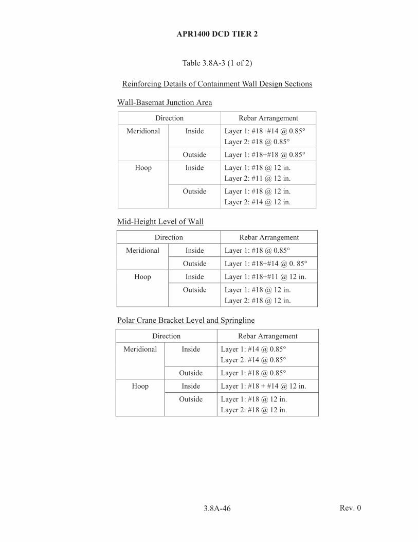
APR1400 DCD TIER 2
3.8A-46
Table 3.8A-3 (1 of 2)
Reinforcing Details of Containment Wall Design Sections
Wall-Basemat Junction Area
Direction Rebar Arrangement
Meridional Inside Layer 1: #18+#14 @ 0.85° Layer 2: #18 @ 0.85°
Outside Layer 1: #18+#18 @ 0.85°
Hoop Inside Layer 1: #18 @ 12 in. Layer 2: #11 @ 12 in.
Outside Layer 1: #18 @ 12 in. Layer 2: #14 @ 12 in.
Mid-Height Level of Wall
Direction Rebar Arrangement
Meridional Inside Layer 1: #18 @ 0.85°
Outside Layer 1: #18+#14 @ 0. 85°
Hoop Inside Layer 1: #18+#11 @ 12 in.
Outside Layer 1: #18 @ 12 in. Layer 2: #18 @ 12 in.
Polar Crane Bracket Level and Springline
Direction Rebar Arrangement
Meridional Inside Layer 1: #14 @ 0.85° Layer 2: #14 @ 0.85°
Outside Layer 1: #18 @ 0.85°
Hoop Inside Layer 1: #18 + #14 @ 12 in.
Outside Layer 1: #18 @ 12 in. Layer 2: #18 @ 12 in.
Rev. 0

APR1400 DCD TIER 2
3.8A-47
Table 3.8A-3 (2 of 2)
Equipment Hatch
Direction Rebar Arrangement
Meridional Inside Layer 1: #18+#14 @ 0.85° Layer 2: #18 @ 0.85°
Outside Layer 1: #18+#18 @ 0.85° Layer 2: #18+#18 @ 0.85° Layer 3: #18+#18 @ 0.85°
Hoop Inside Layer 1: #18 @ 6 in. Layer 2: #18 @ 6 in.
Outside Layer 1: #18 @ 6 in. Layer 2: #18 @ 12 in. Layer 3: #18 @ 12 in. Layer 4: #18 @ 12 in.
Personnel Airlock
Direction Rebar Arrangement
Meridional Inside Layer 1: #18+#14 @ 0.85° Layer 2: #18 @ 0.85° Layer 3: #18 @ 0.85°
Outside Layer 1: #18+#18 @ 0.8° Layer 2: #18+#18 @ 0.8° Layer 3: #18+#18 @ 0.85°
Hoop Inside Layer 1: #18 @ 12 in. Layer 2: #11 @ 12 in.
Outside Layer 1: #18 @ 6 in. Layer 2: #18 @ 12 in. Layer 3: #18 @ 12 in. Layer 4: #14 @ 12 in.
Rev. 0

APR1400 DCD TIER 2
3.8A-48
Table 3.8A-4 (1 of 2)
Rebar Stresses of RCB Wall Design Sections
Wall-Basemat Junction Area
Meridional Hoop
Mechanical Mech. + Thermal Mechanical Mech. + Thermal
Inside (ksi)
Outside (ksi)
Inside (ksi)
Outside (ksi)
Inside (ksi)
Outside (ksi)
Inside (ksi)
Outside (ksi)
41.7 35.3 43.2 53.2 32.2 36.1 28.8 51.4
Mid-Height Level of Wall
Meridional Hoop
Mechanical Mech. + Thermal Mechanical Mech. + Thermal
Inside (ksi)
Outside (ksi)
Inside (ksi)
Outside (ksi)
Inside (ksi)
Outside (ksi)
Inside (ksi)
Outside (ksi)
46.8 33.8 38.4 45.6 39.4 33.6 31.2 50.2
Polar Crane Bracket Level and Springline
Meridional Hoop
Mechanical Mech. + Thermal Mechanical Mech. + Thermal
Inside (ksi)
Outside (ksi)
Inside (ksi)
Outside (ksi)
Inside (ksi)
Outside (ksi)
Inside (ksi)
Outside (ksi)
27.2 18.5 16.4 47.4 43.1 22.4 36.1 43.5
Rev. 0

APR1400 DCD TIER 2
3.8A-49
Table 3.8A-4 (2 of 2)
Equipment Hatch
Meridional Hoop
Mechanical Mech. + Thermal Mechanical Mech. + Thermal
Inside (ksi)
Outside (ksi)
Inside (ksi)
Outside (ksi)
Inside (ksi)
Outside (ksi)
Inside (ksi)
Outside (ksi)
39.4 38.9 39.0 54.0 ( =0.00192)
40.2 32.9 37.9 48.9
Personnel Airlock
Meridional Hoop
Mechanical Mech. + Thermal Mechanical Mech. + Thermal
Inside (ksi)
Outside (ksi)
Inside (ksi)
Outside (ksi)
Inside (ksi)
Outside (ksi)
Inside (ksi)
Outside (ksi)
31.7 37.9 28.7 54.0 ( =0.00192)
51.3 45.6 43.5 53.0
Rev. 0

APR1400 DCD TIER 2
3.8A-50
Table 3.8A-5
Critical Sections of RCB Basemat
Design Section Location Height (ft)
Section-01 Tendon Gallery Outside Area 33
Section-02 Tendon Gallery Upper Area 10
Section-03 Tendon Gallery Below Area 10
Section-04 R = 63.25´ to 70.5´ at El. 45´ to El. 78´ 33
Section-05 R = 42.5´ to 63.25´ Exclude Design Section-06, -07, -08 33
Section-06 Cavity Area at El. 55´ to 66´
11
Section-07 x = 22´ to 39´ and y = 0´ to 18.75´ at El. 55´ to 76´ 21
Section-08 x, y = 0´ to 42.5´ Exclude Design Section -06, -08 23
Rev. 0

APR1400 DCD TIER 2
3.8A-51
Table 3.8A-6
Flexural Forces of RCB Basemat (Service load)
Design Section E-W or Radial Direction
+Mx (Kips-ft/ft)
Fx (Kips/ft)
-Mx (Kips-ft/ft)
Fx (Kips/ft)
Section-01 411.98 -689.04 -294.57 -711.26
Section-02 1,202.21 20.30 -289.72 57.11
Section-03 1,876.71 276.72 55.68 89.49
Section-04 5,601.79 189.17 -68.87 95.11
Section-05 7,300.82 431.25 -1,364.36 174.23
Section-06 321.98 236.43 105.26 223.48
Section-07 2,093.17 121.94 255.36 45.11
Section-08 5,936.07 -65.15 1,401.17 -43.63
Design Section N-S or Hoop Direction
+My (Kips-ft/ft)
Fy (Kips/ft)
-My (Kips-ft/ft)
Fy (Kips/ft)
Section-01 31.96 207.52 -18.41 225.15
Section-02 533.66 -24.90 -75.72 57.28
Section-03 1,732.50 222.78 7.42 27.24
Section-04 5,611.92 405.80 -39.77 163.50
Section-05 8,086.81 483.10 -86.31 235.91
Section-06 216.13 149.51 -225.93 172.38
Section-07 670.62 127.57 30.19 151.43
Section-08 2,685.55 203.26 736.40 124.77
Rev. 0

APR1400 DCD TIER 2
3.8A-52
Table 3.8A-7
Flexural Forces of RCB Basemat (Factored load)
Design Section N-S or Hoop Direction
+Mx (Kips-ft/ft)
Fx (Kips/ft)
-Mx (Kips-ft/ft)
Fx (Kips/ft)
Section-01 534.32 -815.48 -223.03 218.38
Section-02 449.03 312.49 -752.63 257.82
Section-03 1,210.51 434.43 -1,598.54 -826.85
Section-04 5,659.13 191.73 -14,794.69 -1,053.82
Section-05 30,051.97 1,522.57 -24,810.24 -981.30
Section-06 1,237.07 980.91 365.09 729.38
Section-07 5,027.94 1,026.26 -267.80 18.18
Section-08 12,756.73 995.33 -133.87 191.55
Design Section N-S or Hoop Direction
+Mx (Kips-ft/ft)
Fx (Kips/ft)
-Mx (Kips-ft/ft)
Fx (Kips/ft)
Section-01 27.65 329.98 -18.58 229.87
Section-02 29.55 316.72 -91.81 323.26
Section-03 1,625.16 678.40 -761.67 366.43
Section-04 13,196.49 1,865.01 704.96 1,337.85
Section-05 29,036.58 1,859.29 -9,142.08 -365.83
Section-06 296.65 587.14 -29.68 550.36
Section-07 1,028.67 691.40 113.96 527.52
Section-08 8,605.74 1,405.47 -139.63 521.66
Rev. 0

APR1400 DCD TIER 2
3.8A-53
Table 3.8A-8
Shear Forces of RCB Basemat (Service load)
Design Section Nxx (Kips/ft)
Nyy (Kips/ft)
Qxz (Kips/ft)
Qyz (Kips/ft)
Vmax (Kips/ft)
Section-01 -213.58 -34.70 -56.13 12.17 72.28
Section-02 3.89 -102.44 -5.27 234.96 246.23
Section-03 76.70 274.36 -203.02 -49.17 252.19
Section-04 3.34 -50.29 -70.24 -208.75 278.99
Section-05 228.31 303.62 -87.16 -178.73 265.88
Section-06 223.48 166.19 5.33 112.56 202.21
Section-07 153.81 139.42 39.00 -62.25 175.36
Section-08 5.72 111.55 50.75 -249.73 335.54
Rev. 0
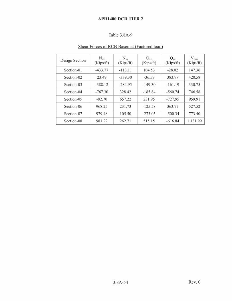
APR1400 DCD TIER 2
3.8A-54
Table 3.8A-9
Shear Forces of RCB Basemat (Factored load)
Design Section Nxx (Kips/ft)
Nyy (Kips/ft)
Qxz (Kips/ft)
Qyz (Kips/ft)
Vmax (Kips/ft)
Section-01 -433.77 -113.11 104.53 -28.02 147.36
Section-02 23.49 -339.30 -36.59 383.98 420.58
Section-03 -388.12 -284.95 -149.30 -161.19 330.75
Section-04 -767.30 328.42 -185.84 -560.74 746.58
Section-05 -82.70 657.22 231.95 -727.95 959.91
Section-06 968.25 231.73 -125.58 363.97 527.52
Section-07 979.48 105.50 -273.05 -500.34 773.40
Section-08 981.22 262.71 515.15 -616.84 1,131.99
Rev. 0
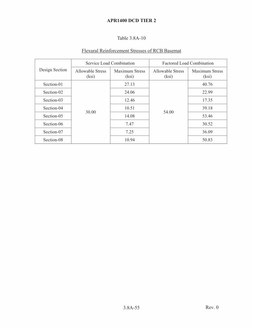
APR1400 DCD TIER 2
3.8A-55
Table 3.8A-10
Flexural Reinforcement Stresses of RCB Basemat
Design Section Service Load Combination Factored Load Combination
Allowable Stress (ksi)
Maximum Stress (ksi)
Allowable Stress (ksi)
Maximum Stress (ksi)
Section-01
30.00
27.13
54.00
40.76
Section-02 24.06 22.99
Section-03 12.46 17.35
Section-04 10.51 39.18
Section-05 14.08 53.46
Section-06 7.47 30.52
Section-07 7.25 36.09
Section-08 10.94 50.83
Rev. 0

APR1400 DCD TIER 2
3.8A-56
Table 3.8A-11
Shear Reinforcement Stresses of RCB Basemat
Design Section Required Reinforcement (in2/ft)
Provided Reinforcement (in2/ft) Remark
Section-01 0.2932 0.3514
Section-02 0.5123 0.7029
Section-03 0.0896 0.1975
Section-04 0.0012 0.1975
Section-05 0.1029 0.1975
Section-06 0.3549 0.3950
Section-07 0.1444 0.1975
Section-08 0.3177 0.3950
Rev. 0

APR1400 DCD TIER 2
3.8A-57
Table 3.8A-12
Summary of the Flexural Reinforcement of the RCB Basemat
Design Section
Flexural Reinforcement
EW or Radial Direction NS or Hoop Direction
Top Bottom Top Bottom
Section-01 1-#[email protected]° 2-#[email protected]° 1-#18@12 2-#18@12
Section-02 1-#[email protected]° 2-#[email protected]°
3-#[email protected]° 3-#18@12 3-#14@12
Section-03 3-#18@12 5-#18@6 3-#18@12 6-#18@6
Section-04 1-#[email protected]° 2-#[email protected]°
5-#18@6 1-#18@6 2-#18@12
6-#18@6
Section-05 1-#[email protected]° 2-#[email protected]°
5-#18@6 1-#18@6 2-#18@12
6-#18@6
Section-06 3-#18@12 1-#18@12 3-#18@6
3-#18@12 1-#18@12 3-#18@6
Section-07 3-#18@12 1-#18@12 3-#18@6
3-#18@12 1-#18@12 3-#18@6
Section-08 3-#18@12 1-#18@12 3-#18@6
3-#18@12 1-#18@12 3-#18@6
Rev. 0
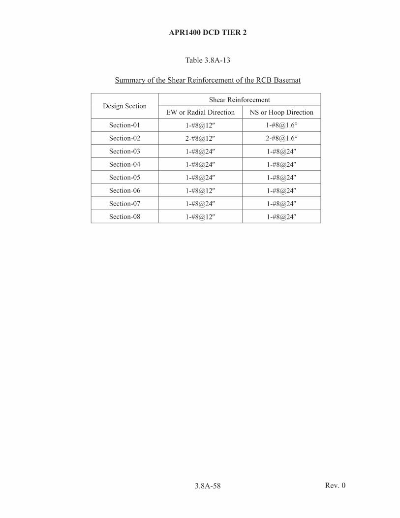
APR1400 DCD TIER 2
3.8A-58
Table 3.8A-13
Summary of the Shear Reinforcement of the RCB Basemat
Design Section Shear Reinforcement
EW or Radial Direction NS or Hoop Direction
Section-01 1-#8@12 1-#[email protected]°
Section-02 2-#8@12 2-#[email protected]°
Section-03 1-#8@24 1-#8@24
Section-04 1-#8@24 1-#8@24
Section-05 1-#8@24 1-#8@24
Section-06 1-#8@12 1-#8@24
Section-07 1-#8@24 1-#8@24
Section-08 1-#8@12 1-#8@24
Rev. 0

APR1400 DCD TIER 2
3.8A-59
Table 3.8A-14
Factor of Safety for Basemat Stability
Load Combination
Minimum Factor of Safety
Overturning Sliding Flotation
D + He + W 1.5 1.5 -
D + He + Es 1.1 1.1 -
D + He + Wt 1.1 1.1 -
D + Hs - - 1.1
D = Dead load He = Static and dynamic lateral and vertical earth pressure including buoyant
effect of normal design ground water level Hs = Buoyant force of the design basis flood W = Wind Load Wt = Tornado Load Es = Safe Shutdown Earthquake
Rev. 0

APR1400 DCD TIER 2
3.8A-60
Table 3.8A-15
Results on Factor of Safety for Basemat Stability
FOS(1) Allowable
FOS Remark
Overturning 1.36 1.10
Sliding 1.51 1.10
Flotation 3.39 1.10
(1) FOS = Factor of Safety
Rev. 0

APR1400 DCD TIER 2
3.8A-61
Table 3.8A-16
Uplift Area Ratios of NI Common Basemat
Soil Profiles
Load Combinations
Area at Bottom of Basemat (ft2) Uplift Area (ft2) Uplift Area Ratios
(%)
Soil #1
LC08
113,590
20,530.86 18.07 %
LC10 3,976.67 3.50 %
LC12 10,393.17 9.15 %
Soil #4
LC08 22,540.91 19.81 %
LC10 2,455.38 2.16 %
LC12 9,933.7 8.75 %
Soil #8
LC08 23,353.56 20.56%
LC10 8,470.57 7.46 %
LC12 17,032.33 14.99 %
Rev. 0

APR1400 DCD TIER 2
3.8A-62
Table 3.8A-17
Differential Settlements According to Site Profiles (Static)
Section Node #1 Node #2 Distance (ft)
Differential Settlement (inches)
Soil #1 Soil #4 Soil #8
AB1 26,810 27,829 48.58 0.103 0.013 0.010
AB2 27,829 29,466 46.26 0.149 0.056 0.022
AB3 29,466 28,901 46.59 0.145 0.045 0.006
AB4 28,901 1,367 44.70 0.176 0.072 0.026
AB5 26,811 27,246 48.73 0.059 0.023 0.020
AB6 27,246 26,610 44.08 0.011 0.013 0.007
AB7 26,610 27,669 41.54 0.005 0.019 0.005
AB8 27,669 790 39.68 0.046 0.053 0.025
AB9 26,620 28,027 48.73 0.152 0.059 0.037
AB10 28,027 26,667 44.08 0.079 0.002 0.014
AB11 26,667 27,610 41.54 0.084 0.011 0.004
AB12 27,610 822 39.68 0.036 0.023 0.014
AB13 26,826 27,117 48.58 0.054 0.011 0.010
AB14 27,117 29,708 46.26 0.106 0.057 0.024
AB15 29,708 30,238 46.59 0.101 0.044 0.007
AB16 30,238 1,466 44.70 0.126 0.071 0.029
RCB1 5,929 18,822 46.06 0.087 0.012 0.005
RCB2 15,931 15,467 47.09 0.009 0.009 0.003
RCB3 6,135 14,571 46.06 0.028 0.002 0.003
RCB4 16,131 15,368 47.09 0.082 0.012 0.004
Total Max. Differential Settlement 0.176 0.072 0.037
Rev. 0
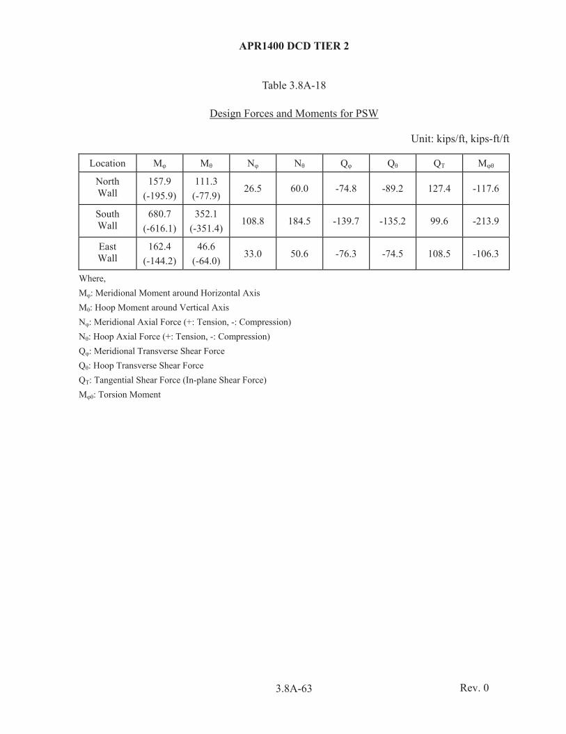
APR1400 DCD TIER 2
3.8A-63
Table 3.8A-18
Design Forces and Moments for PSW
Unit: kips/ft, kips-ft/ft
Location M M N N Q Q QT M
North Wall
157.9 (-195.9)
111.3 (-77.9)
26.5 60.0 -74.8 -89.2 127.4 -117.6
South Wall
680.7 (-616.1)
352.1 (-351.4)
108.8 184.5 -139.7 -135.2 99.6 -213.9
East Wall
162.4 (-144.2)
46.6 (-64.0)
33.0 50.6 -76.3 -74.5 108.5 -106.3
Where, M : Meridional Moment around Horizontal Axis M : Hoop Moment around Vertical Axis N : Meridional Axial Force (+: Tension, -: Compression) N : Hoop Axial Force (+: Tension, -: Compression) Q : Meridional Transverse Shear Force Q : Hoop Transverse Shear Force QT: Tangential Shear Force (In-plane Shear Force) M : Torsion Moment
Rev. 0
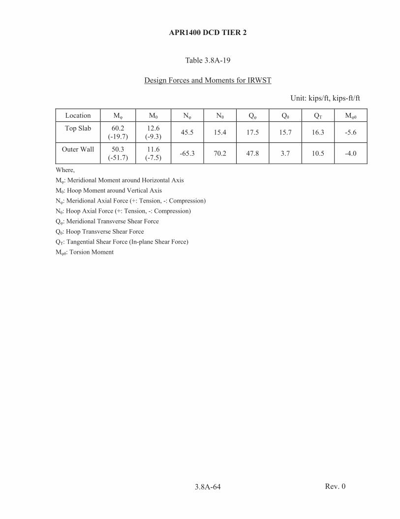
APR1400 DCD TIER 2
3.8A-64
Table 3.8A-19
Design Forces and Moments for IRWST
Unit: kips/ft, kips-ft/ft
Location M M N N Q Q QT M
Top Slab 60.2 (-19.7)
12.6 (-9.3) 45.5 15.4 17.5 15.7 16.3 -5.6
Outer Wall 50.3 (-51.7)
11.6 (-7.5) -65.3 70.2 47.8 3.7 10.5 -4.0
Where, M : Meridional Moment around Horizontal Axis M : Hoop Moment around Vertical Axis N : Meridional Axial Force (+: Tension, -: Compression) N : Hoop Axial Force (+: Tension, -: Compression) Q : Meridional Transverse Shear Force Q : Hoop Transverse Shear Force QT: Tangential Shear Force (In-plane Shear Force) M : Torsion Moment
Rev. 0

APR1400 DCD TIER 2
3.8A-65
Table 3.8A-20
Design Forces and Moments for SSW
Unit: kips/ft, kips-ft/ft
Type M M N N Q Q QT M
SSW (1) 130.9
(-119.8) 240.3
(-130.3) 88.4 154.4 -35.3 54.0 -128.2 -71.2
RFP (2) 1521.6
(-1304.2) 949.7
(-1038.2) 215.6 344.1 232.5 415.5 -158.8 673.6
RFP (3) 89.1
(-74.3) 306.8
(-255.6) 40.4 365.6 32.7 -72.3 -108.9 53.5
SG (4) 430.3
(-335.7) 492.3
(-407.3) 399.2 199.4 114.1 92.2
61.7(7) -111.4(8)
-220.2(7) 280.3(8)
SG (5) 743.5
(-685.3) 703.4
(-603.5) 85.1 211.5 -171.4 -149.5
57.2(7) 116.5(8)
-446.0(7) -324.0(8)
PZR (6) 21.2
(-15.7) 178.8
(-244.7) 173.7 89.6 -1.2 -92.3
135.7(7) 95.2(8)
16.3(7) -69.7(8)
(1) Secondary Shield Wall (Thickness 4 ft) (2) South/North Wall of Refueling pool (thickness 6 ft 2 in) (3) West Wall of Refueling pool (Thickness 5 ft) (4) Circular Wall of Steam Generator (SG) Enclosure (Thickness 4 ft) (5) Straight Wall of Steam Generator (SG) Enclosure (Thickness 5 ft) (6) Pressurizer (PZR) Enclosure Wall (Thickness 2 ft 9 in) (7) These forces are considered with N and M when designing vertical re-bar. (8) These forces are considered with N and M when designing horizontal re-bar.
Where, M : Vertical Moment around Horizontal Axis M : Horizontal Moment around Vertical Axis N : Vertical Axial Force (+: Tension, -: Compression) N : Horizontal Axial Force (+: Tension, -: Compression) Q : Vertical Transverse Shear Force Q : Horizontal Transverse Shear Force QT: In-plane Shear Force
M : Torsion Moment
Rev. 0

APR1400 DCD TIER 2
3.8A-66
Table 3.8A-21
Typical Rebar Arrangement for PSW
Location Meridional Direction Hoop Direction Shear
Reinforcement
North Wall
Inside : #18 & #14 @ 4.5
Outside : #18 & #14 @ 12
Inside : #14 & #14 @ 12
Outside : #14 & #14 @ 12
#8 @ 24" Vert. @ 4.5 Horiz.
East Wall
Inside : 2-#18(Bundled) & #14 @ 4.5
Outside : #18 & #18 & #14 @ 12
Inside : #18 & #14 @ 12
Outside : #18 & #14 @ 12
#8 @ 24" Vert. @ 4.5 Horiz.
South Wall
Inside : #18 & #14 @ 4.5
Outside : #18 & #14 @ 12
Inside : #14 & #14 @ 12
Outside : #14 & #14 @ 12
#8 @ 24" Vert. @ 4.5 Horiz.
Rev. 0

APR1400 DCD TIER 2
3.8A-67
Table 3.8A-22
Typical Rebar Arrangement for IRWST
Location Meridional/Vertical
Direction
Hoop/Horizontal
Direction
Shear
Reinforcement
Top Slab #11 @ 0.9 o
Each Face
#11 @ 12"
Each Face -
Outer Wall #11 @ 0.9 o
Each Face
#11 @ 12"
Each Face
#6 @ 24" Vert.
@ 0.9 o Horiz.
Rev. 0

APR1400 DCD TIER 2
3.8A-68
Table 3.8A-23
Typical Rebar Arrangement for SSW
Location Meridional/Vertical Direction
Hoop/Horizontal Direction
Shear Reinforcement
Secondary Shield Wall #14 & #11 @ 0.9 Each Face
#18 & #14 @ 12 Each Face
#8 @ 12 Vert. @ 1 48 Horiz.
Refueling Pool Wall
South/ North
2-#18(Bundled) & #14 @ 12 Each Face
2-#18(Bundled) & #18 @ 12 Each Face
2-#8 @ 12 Vert. @ 9 Horiz.
West #11 & #11 @ 12 Each Face
#18 & #18 @ 12 Each Face
#6 @ 12 Vert. @ 12 Horiz.
SG Enclosure
Wall
Circular #18 & #18 @ 0.9 Each Face
2-#14 & #18 @ 12 Each Face
2-#7 @ 12 Vert. @ 1 Horiz.
Straight #18 & #18 @ 12 Each Face
2-#14 #18 @ 12 Each Face
2-#7 @ 12 Vert. @ 12 Hor.
PZR Enclosure Wall
2-#11(Bundled) & #11 @ 12 Each Face
#18 & #14 @ 12 Each Face
#8 @ 12 Vert. @ 12 Hor.
Rev. 0

APR1400 DCD TIER 2
3.8A-69
Table 3.8A-24
Enveloped Design Forces of the AB Basemat
Element Set No.
Governing Load
Combinations
Nx kip/ft
Ny kip/ft
Mx kip-ft/ft
My kip-ft/ft
Vxz kip/ft
Vyz kip/ft
Vin_x kip/ft
Vin_y kip/ft Remarks
1 LC11 362.0 500.3 901.1 1,514.5 95.3 159.3 -712.0 -712.0
2 LC9 298.3 409.5 930.4 1,319.8 81.6 210.1 634.7 634.7
3 LC15 -471.4 142.7 1,969.0 1,211.5 216.7 37.0 304.1 304.1
4 LC13 -479.6 112.4 2,268.5 1,428.9 234.8 50.9 -332.6 -332.6
5 LC6 -482.6 262.4 2,341.8 1,406.9 285.4 128.6 325.2 321.9
6 LC13 -465.7 229.8 2,637.7 1,557.6 304.3 146.6 -353.0 -356.8
7 LC6 258.9 434.8 1,066.2 330.4 138.7 49.7 -46.9 -86.7
8 LC11 1,151.2 521.0 1,148.5 1,503.5 101.8 155.0 -278.7 -208.3
9 LC9 1,006.8 435.2 1,220.5 1,309.9 72.3 156.7 244.4 182.9
10 LC14 -195.4 -54.9 612.2 584.5 134.4 99.2 -454.6 -454.6
11 LC9 -450.1 -126.2 725.8 1,181.7 38.8 205.9 446.6 446.6
12 LC9 -274.3 193.8 2,082.1 1,667.6 595.1 122.4 -574.2 -586.4
13 LC6 110.8 -5.4 370.0 1,196.3 85.5 153.3 -52.7 -21.0
14 LC15 -200.0 57.5 889.4 358.0 91.2 134.4 -352.5 -352.5
15 LC11 -466.1 -765.9 575.6 1,231.8 126.9 187.5 -225.0 -95.6
(1) The location of the element sets is shown in Table 3.8A-. X-axis is in EW direction, and Y-axis is in NS direction. Governing load combinations are as follows; LC6: 1.4D+1.7L+1.4Lh+1.0F LC9: 1.0D+1.0L+1.0Lh+1.0F+1.0Pa+1.0Yr+1.0Es02 LC11: 1.0D+1.0L+1.0Lh+1.0F+1.0Pa+1.0Yr+1.0Es04 LC13: 1.0D+1.0L+1.0Lh+1.0F+1.0Pa+1.0Yr+1.0Es06 LC14: 1.0D+1.0L+1.0Lh+1.0F+1.0Pa+1.0Yr+1.0Es07 LC15: 1.0D+1.0L+1.0Lh+1.0F+1.0Pa+1.0Yr+1.0Es08
Rev. 0

APR1400 DCD TIER 2
3.8A-70
Table 3.8A-25
Required Reinforcement of the AB Basemat
Element Set No.
Required Top and Bottom Bar Shear Bar
EW-Direction NS-Direction
1 3-#18@12″ 3-#18@12″ #6@12″
2 2-#18@12″ 3-#18@12″ #5@12″
3 3-#14@12″ 3-#11@12″ #5@12″
4 3-#14@12″ 3-#11@12″ -
5 3-#14@12″ 3-#14@12″ #6@12″
6 2-#18@12″ 3-#14@12″ #6@12″
7 3-#14@12″ 3-#14@12″ #5@12″
8 3-#18@12″ 3-#18@12″ #5@12″
9 3-#18@12″ 2-#18@12″ #5@12″
10 3-#11@12″ 3-#11@12″ #5@12″
11 3-#11@12″ 3-#11@12″ #5@12″
12 3-#18@12″ 3-#18@12″ 2-#8@12″
13 2-#11@12″ 3-#11@12″ #5@12″
14 3-#11@12″ 3-#11@12″ #5@12″
15 2-#11@12″ 3-#11@12″ #5@12″ (1) The element sets of the auxiliary building basemat are composed as following:
Rev. 0

APR1400 DCD TIER 2
3.8A-71
Table 3.8A-26
Enveloped Design Forces of the AB Shear Wall
Element Set No. Zone Elevation
Governing Load
Combinations N11 kip/ft
N22 kip/ft
M11 kip-ft/ft
M22 kip-ft/ft
Qout kip/ft
N12 kip/ft
North wall of north MSIV house
1 55 -0 to 100 -0
LC15C 44.8 32.9 106.5 106.1 64.8 191.5
2 100 -0 to 120 -0
LC15C 30.6 87.6 152.0 147.1 70.9 259.2
3 120 -0 to 137 -6
LC15A 68.9 29.5 128.4 72.8 34.4 218.5
4 137 -6 to 174 -0
LC15A 112.8 7.5 55.1 65.5 2.1 120.9
North wall of north AFWST
1 100 -0 to 137 -6
LC15B -53.9 -144.0 74.3 124.59
68.9 165.6
West wall of MCR
1 55 -0 to 100 -0
LC15B -56.3 -305.0 86.8 53.3 55.5 228.42
2 100 -0 to 137 -6
LC15C -59.6 -277.4 76.8 67.7 56.1 166.1
3 137 -6 to 156 -0
LC15C -196.9 -146.7 29.3 27.1 12.8 194.5
4 156 -0 to 174 -0
LC15B 20.1 -15.4 28.9 51.8 39.6 90.3
5 174 -0 to 195 -0
LC15C -87.2 -18.8 44.7 73.9 17.5 65.0
West wall of SFP
1 114 -0 to 156 -0
LC15B -51.3 -270.0 248.9 288.4 118.8 291.2
East wall of FHA
1 156 -0 to 174 -0
LC15C 72.4 -1.6 69.5 69.2 59.7 131.2
2 174 -0 to 213 -6
LC15B -68.2 -155.8 125.8 222.1 20.1 165.6
(1) 11 is in horizontal direction, and 22 is in vertical direction. (2) Design forces and moments in this table are the enveloped values of the following load combinations; L.C.4; 1.4 D + 1.7 (L+ Lg_s) + 1.4 Lh + 1.4 Ro L.C.6; 1.4 D + 1.7 (L+ Lg_s)+ 1.4 Lh + 1.7 W L.C.15A ; 1.0 D + 1.0 L + 1.0 Lh + 1.0 Lg_s + 1.0 Es + 1.0 Lg_d L.C.15B ; 1.0 D + 1.0 L + 1.0 Lh + 1.0 Lg_s - 1.0 Es + 1.0 Lg_d L.C.15C ; 0.9 D + 1.0 Lh + 1.0 Lg_s + 1.0 Es + 1.0 Lg_d L.C.15D ; 0.9 D + 1.0 Lh + 1.0 Lg_s - 1.0 Es + 1.0 Lg_d
Rev. 0

APR1400 DCD TIER 2
3.8A-72
Table 3.8A-27
Required Reinforcement Summary of the AB Shear Wall
Critical Section Zone Elevation Horizontal Vertical Shear
North wall of north MSIV
house
1 55 -0 to 100 -0 2-#11@9 2-#11@9 -
2 100 -0 to 120 -0 2-#11@9 2-#11@9 #6@9
3 120 -0 to 137 -5 2-#11@9 2-#11@9 -
4 156 -0 to 174 -0 2-#11@9 2-#14@9 #5@9
4-aircraft 156 -0 to 174 -0 3-#14@9 3-#14@9 #6@9
North wall of north AFWST 1 100 -0 to 137 -6 2-#11@9 2-#11@9 -
West wall of MCR
1 55 -0 to 100 -0 2-#11@12 2-#11@12 #5@12
2 100 -0 to 137 -6 2-#11@12 2-#11@12 -
3 137 -6 to 156 -0 2-#10@12 2-#10@12 -
4 156 -0 to 174 -0 #11@12 2-#10@12 #6@12
5 174 -0 to 195 -0 #11@12 #11@12 -
West wall of SFP
1 114 -0 to 156 -0 #11@9 #14@9 #5@9
East wall of FHA area
1 156 -0 to 174 -0 2-#11@9 2-#14@9 #7@9
2 174 -0 to 213 -6 2-#10@9 2-#11@9
Rev. 0

APR1400 DCD TIER 2
3.8A-73
Table 3.8A-28
Enveloped Design Forces of the EDG Room Slab in AB
Location Design Force and Moments
Critical Joint No.
Governing Load
Combination
Mxx (kip-ft/ft)
Myy (kip-ft/ft)
Mxy (kip-ft/ft)
Vxx (kip/ft)
Vyy (kip/ft)
EDG-1 zone at Elevation
100 '-0 (24 thick)
Max. positive Mxx
195 LC15D 15.9 10.31 0.15 0.93 0.26
196 LC15D 14.55 9.53 1.66 0.83 -0.27
Max. negative Mxx
443 LC15A -21.55 0.34 -0.72 -7.55 -0.11
450 LC15A -19.11 1.34 -0.42 -6.21 -0.16
Max. positive Myy
182 LC15D 12.12 11.58 0.50 0.68 0.08
188 LC15D 12.82 11.23 0.84 1.07 -0.10
Max. negative Myy
264 LC15A -5.99 -27.97 -0.79 0.54 5.18
185 LC15A -6.66 -27.13 -1.15 -1.83 -0.58
Max.Vxx 443 LC15A -21.55 0.34 -0.72 -7.55 -0.11
442 LC15A -18.89 -1.43 0.93 -6.75 -0.17
Max. Vyy 264 LC15D -3.47 -15.37 1.37 1.00 7.56
179 LC15D -2.98 -14.41 1.26 -0.73 7.18
EDG-2 zone at Elevation
100 -0 (48 thick)
Max. positive Mxx
1114 LC15D 27.51 14.68 31.71 38.79 3.68
791 LC15D 25.53 42.98 -0.85 0.24 -0.32
Max. negative Mxx
434 LC15A -29.26 -86.84 -23.22 8.08 13.89
453 LC15A -23.46 -32.54 1.37 -0.25 -40.74
Max. positive Myy
450 LC15D -5.46 50.99 -2.00 3.34 2.98
620 LC15D 16.12 46.93 -1.56 2.22 1.61
Max. negative Myy
434 LC15A -29.26 -86.84 -23.22 8.08 13.89
786 LC15A -16.21 -86.42 1.29 -0.22 -3.87
Max. Vxx 1114 LC15D 27.51 14.68 31.71 38.79 3.68
539 LC15D 13.59 -7.88 31.82 26.07 4.50
Max. Vyy 453 LC15A -23.46 -32.54 1.37 -0.25 -40.74
452 LC15A -13.22 11.65 -5.60 -0.84 -22.68
(1) X is in EW direction, and Y is in NS direction. (2) Governing load combinations are as follows; - LC15A = D+L+ES (downward) + Pa (downward) - LC15D = 0.9D+L+ES (upward) + Pa (upward) where, Pa: Compartment pressure due to HELB
Rev. 0

APR1400 DCD TIER 2
3.8A-74
Table 3.8A-29
Enveloped Design Forces of the SFP Slab in AB
Location Load Case Design Force and Moments
Critical joint at model
Nxx (kip/ft)
Nyy (kip/ft)
Mxx (kip-ft/ft)
Myy (kip-ft/ft)
Vout (kip/ft)
Nxy (kip/ft)
SFP slab at
Elevation 114 -0
Mechanical Load(1)
Max. positive Mxx 42,941 34.5 22.8 142.4 176.3 210.2 -224.4
Max. negative Mxx
42,944 377.8 375.3 127.9 77.9 130.1 -89.2
Max. positive Myy 70,093 30.0 27.3 122.6 216.2 120.2 -133.6
Max. negative Myy
42,939 98.2 198.9 72.4 162.8 116.0 -90.4
Thermal Load(2)
Max. positive Mxx 42,941 -408.1 -467.4 -1,098.5 -855.4 108.3 134.7
Max. negative Mxx
42,944 -311.2 -501.5 -161.5 -379.0 51.5 337.7
Max. positive Myy 70,093 -581.2 -590.9 -7,724.5 -790.6 22.1 95.0
Max. negative Myy
42,939 -279.5 -395.5 -1,222.5 -899.8 188.8 103.4
(1) Mechanical loads are member forces combining the results obtained from structural analysis with those obtained from hydrodynamic analysis at spent fuel pool.
(2) Thermal loads are member forces induced by temperature difference during abnormal operating conditions.
Rev. 0

APR1400 DCD TIER 2
3.8A-75
Table 3.8A-30
Enveloped Design Forces of the MSE Slab in AB
Location Design Force and Moments
Critical joint at model
Load Combination
Mxx (kip-ft/ft)
Myy (kip-ft/ft)
Mxy (kip-ft/ft)
Vxx (kip/ft)
Vyy (kip/ft)
MSE slab at Elevation
157 6
Max. positive Mxx
619 LC15A 93.8 135.8 0.6 0.6 -6.9
688 LC15A 88.7 125.0 -4.6 -7.3 -6.5
Max. negative Mxx
887 LC15A -146.8 -29.8 -7.1 -8.1 3.2
343 LC15A -105.9 -45.0 4.5 -9.5 2.0
Max. positive Myy
618 LC15A 88.6 138.6 -0.6 0.5 8.0
619 LC15A 93.8 135.8 0.6 0.6 -6.9
Max. negative Myy
1392 LC15A -45.8 -123.9 2.3 1.6 -57.5
1265 LC15A -40.5 -111.9 -1.4 -12.9 -67.9
Max. Vxx 1557 LC15A 6.9 13.4 -11.2 -43.1 -3.4
412 LC15A -9.4 28.5 13.8 39.2 -3.1
Max. Vyy 622 LC15A -35.9 -211.7 0.4 -0.3 -60.1
691 LC15A -35.8 -201.7 -6.2 10.7 -57.7
(1) X is in EW direction, and Y is in NS direction. (2) overning load combinations are as follows: - LC15A = D+L+ES (downward)+ Pa (downward) - LC15D = 0.9D+L+ES (upward)+ Pa (upward) where, Pa: Compartment pressure due to HELB
Rev. 0

APR1400 DCD TIER 2
3.8A-76
Table 3.8A-31
Slab Reinforcement at Each Critical Section in AB
Location Direction Top Rebar Arrangement
Bottom Rebar Arrangement
EDG slab at El.
100 -0
E-W (EDG-1)
#9 @ 9 #7 @ 9
N-S (EDG-1)
#7 @ 9 #6 @ 9
E-W (EDG-2)
#9 @ 9 #8 @ 9
N-S (EDG-2)
#9 @ 9 #9 @ 9
MSE slab at El.
137 -6
E-W #9 @ 9 #9 @ 9
N-S #10 @ 9 #9 @ 9
SFP slab at El.
114 -0
E-W 2-#14@9 2-#14@9
N-S 2-#14@9 2-#14@9
Rev. 0
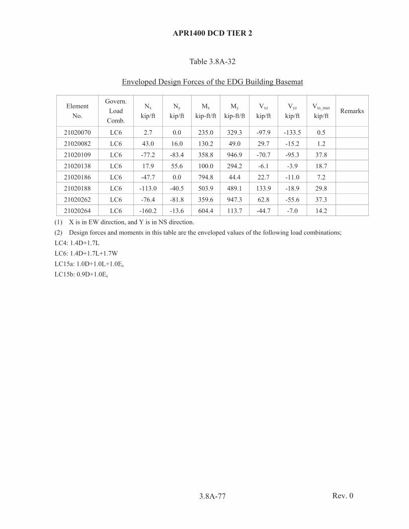
APR1400 DCD TIER 2
3.8A-77
Table 3.8A-32
Enveloped Design Forces of the EDG Building Basemat
Element No.
Govern. Load
Comb.
Nx kip/ft
Ny kip/ft
Mx kip-ft/ft
My kip-ft/ft
Vxz kip/ft
Vyz kip/ft
Vin_max kip/ft
Remarks
21020070 LC6 2.7 0.0 235.0 329.3 -97.9 -133.5 0.5
21020082 LC6 43.0 16.0 130.2 49.0 29.7 -15.2 1.2
21020109 LC6 -77.2 -83.4 358.8 946.9 -70.7 -95.3 37.8
21020138 LC6 17.9 55.6 100.0 294.2 -6.1 -3.9 18.7
21020186 LC6 -47.7 0.0 794.8 44.4 22.7 -11.0 7.2
21020188 LC6 -113.0 -40.5 503.9 489.1 133.9 -18.9 29.8
21020262 LC6 -76.4 -81.8 359.6 947.3 62.8 -55.6 37.3
21020264 LC6 -160.2 -13.6 604.4 113.7 -44.7 -7.0 14.2
(1) X is in EW direction, and Y is in NS direction. (2) Design forces and moments in this table are the enveloped values of the following load combinations; LC4: 1.4D+1.7L LC6: 1.4D+1.7L+1.7W LC15a: 1.0D+1.0L+1.0Es LC15b: 0.9D+1.0Es
Rev. 0

APR1400 DCD TIER 2
3.8A-78
Table 3.8A-33
Enveloped Design Forces of the EDG Building Shear Wall
Element Set No. Elevation Max./
Min N11 kip/ft
N22 kip/ft
M11 kip-ft/ft
M22 kip-ft/ft
Qout kip/ft
N12 kip/ft
West wall of EDG building 100 -6
to 135 -0
Max. 0.05 22.03 42.88 39.3 12.96 41.4
Min -104.2 -20.7 -68.5 -32.8 -12.9 -41.3
Center wall of EDG building
Max. 0.0 21.19 8.56 3.77 5.67 38.94
Min -68.59 -13.61 -8.68 -3.70 -5.68 -15.27
(1) Design forces and moments in this table are the enveloped values of the following load combinations; LC4: 1.4D+1.7L LC6: 1.4D+1.7L+1.7W LC15a: 1.0D+1.0L+1.0Es LC15b: 0.9D+1.0Es
Rev. 0
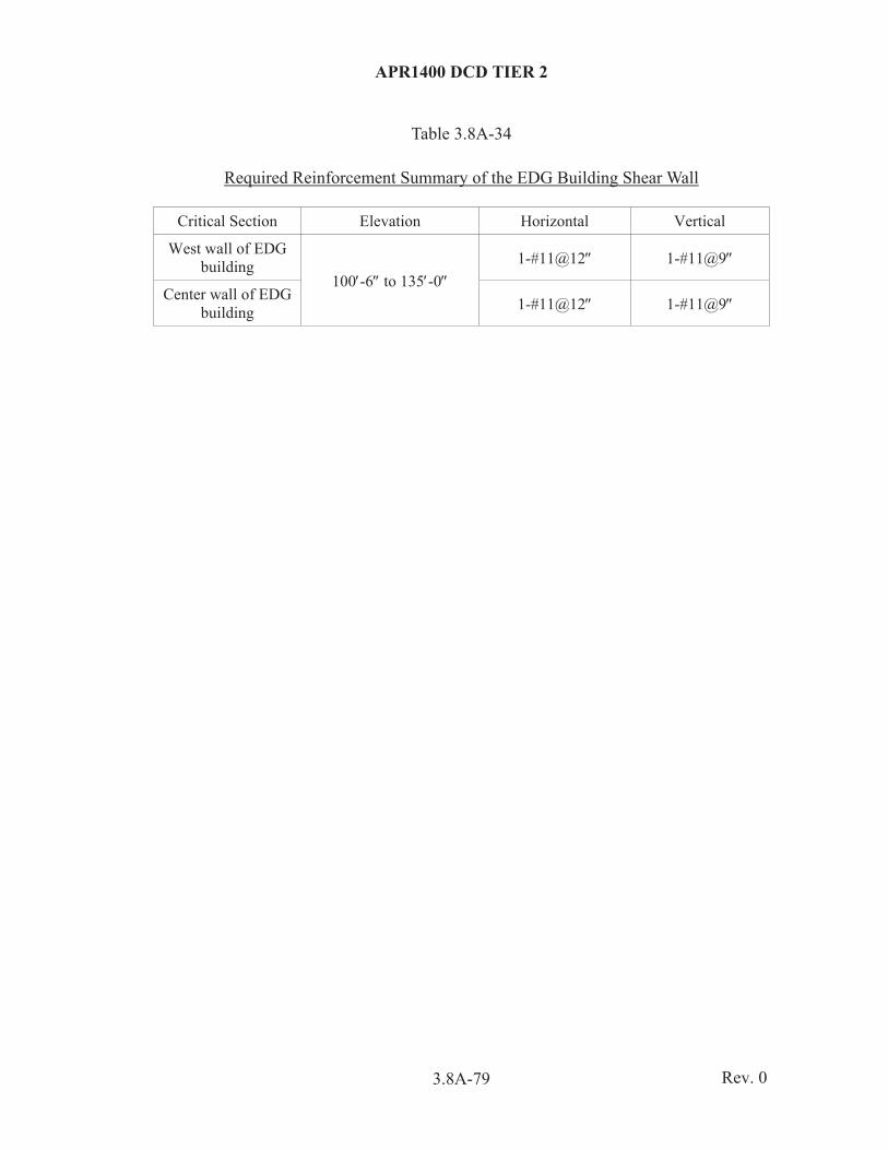
APR1400 DCD TIER 2
3.8A-79
Table 3.8A-34
Required Reinforcement Summary of the EDG Building Shear Wall
Critical Section Elevation Horizontal Vertical
West wall of EDG building
100 -6 to 135 -0 1-#11@12 1-#11@9
Center wall of EDG building 1-#11@12 1-#11@9
Rev. 0