Embed Size (px)
Citation preview

GUELPH | OWEN SOUND | LISTOWEL | KITCHENER | LONDON | HAMILTON | GTA
650 WOODLAWN RD. W., BLOCK C, UNIT 2, GUELPH ON N1K 1B8 P: 519-824-8150 F: 519-824-8089 WWW.GMBLUEPLAN.CA
Appendix ‘E ’ – Excerpts from Recent Structural Inspections

PEOPLE | ENGINEERING | ENVIRONMENTS
GUELPH | OWEN SOUND | LISTOWEL | KITCHENER | LONDON | HAMILTON | GTA
650 WOODLAWN RD. W., BLOCK C, UNIT 2, GUELPH ON N1K 1B8 P: 519-824-8150 F: 519-824-8089 WWW.GMBLUEPLAN.CA
February 16, 2018
Our File: 117085-1
Mr. Jared Puppe
Township of Woolwich
24 Church Street West
Elmira, Ontario N3B 2Z6
Re: Enhanced OSIM and Load Limit Report
Peel Street Bridge (Winterbourne Bridge)
Structure 270148
Dear Mr. Puppe,
GM BluePlan Engineering Limited (GMBP) was retained by the Township of Woolwich (Township) to complete an Enhanced OSIM inspection and a load limit report for Peel Street Bridge located on Peel Street, 600m west of Katherine Street in Winterbourne. As a part of this assignment, the existing structure was inspected and analyzed for the purposes of determining the current load limit to be posted and to identify and assess the various rehabilitation and replacement options as part of the Municipal Class Environmental Assessment (MCEA) process. GMBP attended the site on August 31
st and September 11
th, 2017 to complete our inspection of the structure. Element geometry,
orientation and defects were measured and recorded, and the overall condition of each element was determined following the guidelines of the Ontario Structure Inspection Manual (OSIM).
For the purposes of this letter report, refer to Figure 1 for a visual representation of the nomenclature used for our inspection.
Background
The Peel Street Bridge, also known as the Winterbourne Bridge or Structure #270148, was constructed in the early 1900’s and is a two-span steel truss bridge located on Peel Street, 600m west of Katherine Street in Winterbourne. This structure is a single lane bridge with current posted load limit of 3 tonnes. The load limit has remained through a series of rehabilitation projects from the early 1990s to a 2001 deck replacement, as well as numerous biennial load limit reviews. There are height limiting structures on the east and west ends of the bridge with roadside signs specifying that only one vehicle is permitted on the bridge at a time. The structure has been recommended for replacement or major rehabilitation several times by multiple engineering consultants for more than 10 years.

PEOPLE | ENGINEERING | ENVIRONMENTS
GUELPH | OWEN SOUND | LISTOWEL | KITCHENER | LONDON | HAMILTON | GTA
650 WOODLAWN RD. W., BLOCK C, UNIT 2, GUELPH ON N1K 1B8 P: 519-824-8150 F: 519-824-8089 WWW.GMBLUEPLAN.CA
Figure 1: Glossary of Terms for Peel Street Bridge

PAGE 3 OF 21
OUR FILE:117085-1
GUELPH | OWEN SOUND | LISTOWEL | KITCHENER | LONDON | HAMILTON | GTA
Enhanced OSIM Inspection Summary
The following deficiencies below have been identified by GMBP during the enhanced 2017 OSIM inspection. The deficiencies have been categorized as being major or minor depending on their structural significance. Major deficiencies are considered to be critical and must be addressed to maintain the structural integrity of the bridge. Minor deficiencies are not classified as urgent and can be addressed at a later time though consideration should be given to addressing all deficiencies under one project.
For the purpose of this report, all bridge elements have used the following convention for their location:
Bays – All bays increase in number from east to west.
Stringers – All stringers increase in number from north to south.
Floor Beams - All floor beams increase in number from east to west.
Pin connections – All pin connections increase in number from east to west with first pin counted at east bearing.
Example: Diagonal spanning N3-4 – diagonal spanning between 3rd
top pin connection and 4th bottom pin connection
on north truss.
Major Deficiencies:
Roller pins are dislodged for the south bearing on the west abutment. Disengagement of steel side plate
connecting roller pins in south and north bearing on the west abutment. Significant debris build-up noted
around the roller pins. Refer to photos 1 and 2.
Medium to severe corrosion of stringers throughout the structure with isolated complete section loss noted at
the bottom of web in bay 1 and 18 near abutments and isolated locations throughout. Refer to photos 3 and 4.
Severe corrosion with approximately 60% isolated section loss noted on stringers throughout the structure.
Photos 5 and 6 show a before and after of full rust removal using a flat screw driver on the top flange of a
stringer. Photos 7 and 8 show more examples of isolated section loss for various stringers.
Approximately 15mm sagging noted in 4 stringers in bay 9 at the pier support. Absence of steel bearing plate
to concrete pier for stringers in bay 9. Refer to photos 9 and 10.
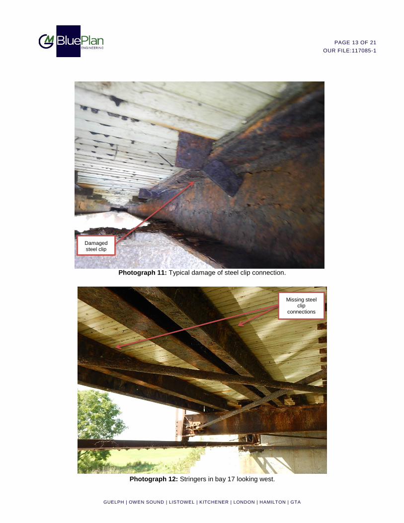
Several steel clip plates connecting the top flange of stringers to the timber deck are damaged or missing.
Refer to photos 11 and 12.
Top laterals spanning: N3-S2, N5-S4, N5-S6, N7-S6, N8-S7, N13-S14 are loose with visible sagging of
members.
Severe corrosion with complete section loss of isolated rivet heads noted at each connection between the end
post and bottom chord (N1, N10, N11, N20, S1, S10, S11, and S20 bearing). Refer to photos 13 and 14.
Isolated complete section loss noted on S20 bearing gusset plate. Refer to photo Refer to photos 13.
Broken anchor bolt noted on bearing S20. Severe corrosion of anchor bolt noted on bearing N20. Refer to
photos 15 and 16.
Severe corrosion with approximately 30% isolated section loss noted on diagonals spanning N3-4, N6-7, N16-
17, N17-18, S5-4, S5-6, S7-6, S15-16, and S16-17 at the bottom chord pin connection. Refer to photos 17 and
18.
Exterior diagonals in north truss spanning N3-4, and N8-7 and interior diagonals in south truss spanning S9-8
are loose.
Steel crack and spall noted on pin nut at top chord to end post connection: N2, N9, S2, S9,S12, S19. Refer to
photos 19 and 20.

PAGE 4 OF 21
OUR FILE:117085-1
GUELPH | OWEN SOUND | LISTOWEL | KITCHENER | LONDON | HAMILTON | GTA
Minor Deficiencies:
Severe concrete delamination, spalling, and scaling noted throughout pier, abutments, and wingwalls. Refer to
photo 21.
Severe distortion of steel posts in south-east and south-west approach barrier. Refer to photo 22.
Severe deformation of railings throughout, with locations of missing horizontal rails. Refer to photo 23.
Rust pack build-up noted between several steel bearing plates and stringer’s bottom flanges. Refer to photo 24
Minor impact damaged noted in portal frame member on east end of bay 1. Refer to photo 25.
Minor impact damage noted in vertical S8 and S13. Refer to photo 26.
Visible deflection of bottom chord spanning N3-4, and S15-16. Refer to photo 27.
Light to severe rust pack, up to 20mm thick, noted between several structural connections throughout the
structure. Refer to photo 28.
Rust debris build-up on top of abutment seats, bearings, bottom flanges in stringers and floor beams.
Load Limit Evaluation
A finite element analysis was completed using S-Frame (v11) software to determine the member-by-member loading of the truss and bridge deck elements as per the Canadian Highway Bridge Design Code, CSA S6-14 (CHBDC). Three “Evaluation Levels” were considered using the CL#-625-ONT design truck loading, where the “#” refers to the Evaluation Level. Evaluation Level 1 consists of a vehicle train with five axles weighing a total of 625 kN (CL-625-ONT truck) or 80% of the CL-625-ONT truck combined with a uniformly distributed lane load. Evaluation Level 1 is the same loading used for design of current day bridges in Ontario. Evaluation Level 2 and Evaluation Level 3 consist of a 505 kN two-unit vehicle with four axles and a 330 kN single unit vehicle with three axles, respectively.
Additionally, completing the enhanced OSIM prior to the load limit evaluation provided information we did not have from traditional access during normal OSIM type inspections.
Another input into our analysis was report SRR-88-04 “Bridge Testing – A Surprise Every Time” published by the Research and Development Branch of the Ministry of Transportation of Ontario (1988), written by B. Bakht and L.G. Jaeger. Section 3 Steel Truss Bridges relates to the Peel Street Steel Truss Bridge. Subsection 3.1 – Load Sharing between Components states:
“When relatively old bridges with truly pin-connected steel trusses were tested recently, it was found that the two component members of the various tension chords of the trusses shared the load very unevenly…Bakht and Jaeger (1987) have concluded that because of the brittle nature of the steels used in these relatively old pin-connected trusses, it may be prudent to include only one component member in the calculation of the capacity of the tension chord.”
Subsection 3.2 – Interaction of the Floor System with the Bottom Chord states:
“The bottom chord strains…were found to be smaller, by a factor of about 15, than the strains which would have occurred if the chord sustained all the force itself. It is obvious that in this case, the stringers of the floor system sustained a large share of the tensile force in the two trusses…
The surprising feature relates to the bottom chord strains in the panel closest to the right hand support of the truss. It can be seen… that the strains in this panel are about 15 times larger than the strains in the adjacent panel. Since the two panels have components of the same section, it is obvious from simple statics that the bottom chord force in the two panels should be very nearly the same. The fact that the total strains in the bottom chords of the two panels are so significantly different from each other suggests that the floor system does not participate with the bottom chord in the end panel.
…All stringers of the floor system… are connected to the truss nodes in such a way that the bottom chord between adjacent nodes cannot deform without engaging the stringers. (For floor systems that do not) have a floor beam at the

PAGE 5 OF 21
OUR FILE:117085-1
GUELPH | OWEN SOUND | LISTOWEL | KITCHENER | LONDON | HAMILTON | GTA
end node... (such as) the bottom chord in the end panel, by deforming independently of the stringers, is called upon to sustain all the tensile forces of the truss.”
Based on the above, any tension member that contained two separate dual elements were analyzed with the assumption that only one of the two elements were relied upon to carry the induced forces. Also, the end bay bottom chords were analyzed separately from bays where stringers were supported and reasonably attached to floor beams at either end.
Based on the results of the Enhanced OSIM and load rating analysis (see Table 1 below), it is our professional recommendation that the existing structure be closed to all traffic due to the severe deterioration of stringers in the end bays and other isolated locations.
Table 1: Load Limit Analysis Results for Peel Street Bridge (270148)
Element Loading Failure Mode Live Load
Capacity Factor (F)
Corresponding Load Limit
Recommended Load Limit
Stringers
CL1-625-ONT
Shear & Bending
N/A < 2
Closed CL2-625-ONT N/A < 2
CL3-625-ONT N/A < 2
Additionally, Section 14 of the CHBDC does not refer to the evaluation of substructure elements. Based on the defects observed by GMBP during our inspection, we do not believe that substructure elements are a limiting factor in the capacity of the structure. Failures of these elements, such as abutments, are anticipated to be gradual, and not sudden. Thus, the risks associated with sudden failure are anticipated to be low. The substructure should continue to be monitored on an annual basis to monitor the progression of defects indicating failure of the elements.
Increasing the Recommended Load Limit to 3 Tonne (Re-open Bridge)
Provided below in Table 2 are the major elements that would require replacement or substantial structural reinforcement to allow the load limit to be increased back to the original 3 tonnes. Please note that these elements should be considered as the minimum scope of work required to achieve a 3 tonne load limit. Considering continued degradation over time of all truss elements, it may be in the Township’s interest to rehabilitate or replace additional truss members beyond those noted below.
Table 2: Elements Requiring Reinforcement or Replacement to Increase Load Limit to 3 Tonnes
Element Failure Mode Load Posting for
Element Quantity Requiring
Upgrades
Stringers Shear & Bending < 2 40
It is recommended that the deck clips are replaced or reinstalled for all the stringers requiring replacement. All new stringers shall have a stronger beam section as well as be treated with an anti-corrosion coating to account for future deterioration.
The following work is recommended to be completed along with the above noted stringer replacements.
Reset or replace the existing rollers in bearings;
Replace all broken or severely corroded anchor bolts at bearings;
All stringers bearing on the pier shall be provided with proper steel plate or elastomeric bearings;
Repair the damaged portal frame on east end of bridge;
Reinforce all loose diagonal members with turnbuckles and cables; and,
Repair or replace cracked and/or spalled pin nuts at top chord to end post connection.

PAGE 6 OF 21
OUR FILE:117085-1
GUELPH | OWEN SOUND | LISTOWEL | KITCHENER | LONDON | HAMILTON | GTA
Increasing the Recommended Load Limit to 6 Tonnes
Provided below in Table 3 are the major elements that would require replacement or substantial structural
reinforcement to allow the load limit to be increased to 6 tonnes.
Table 3: Elements Requiring Reinforcement or Replacement to Increase Load Limit to 6 Tonnes
Element Failure Mode Load Posting for
Element Quantity Requiring
Upgrades
Stringers Shear & Bending < 2 162
There are currently 189 stringers among the 18 bays of the bridge. Various bays have had multiple iterations of stringer replacements where some poor condition stringers were left in place. Unmodified bays contain nine (9) stringers and there are a total of 18 bays. Therefore it is recommended that a total of 162 stringers are replaced to increase the load limit to 6 tonnes. The new stringers shall have a stronger beam section as well as be treated with an anti-corrosion coating to account for future deterioration.
If the Township wishes to increase the posted load limit of the structure beyond the previous 3 tonnes, it is recommended that they use this opportunity to address some of the other deficiencies associated with the structure that include:
Repairs to the concrete abutments and pier;
Replacement of the substandard traffic barrier over the structure;
Replacement of the substandard approach barriers at each end of the structure;
Miscellaneous steel repairs; and,
Waterproofing and resurfacing of wood deck.
Increasing the Recommended Load Limit to 8 Tonnes
Provided below in Table 4 are the elements that would require replacement or substantial structural reinforcement to allow the load limit to be increased to 8 tonnes. Please note that these elements should be considered as the minimum scope of work required to achieve an 8 tonne load limit. Considering continued degradation over time of all truss elements, it may be in the Township’s interest to rehabilitate or replace additional truss members beyond those noted below.
Table 4: Elements Requiring Reinforcement or Replacement to Increase Load Limit to 8 Tonnes
Element Failure Mode Load Posting for
Element Quantity Requiring
Upgrades
Stringers Shear & Bending < 2 162
Diagonals Tension 6 48
Deck Bending 7 -
For each scenario in the table above, subsequent analyses have not been completed to determine the effects on all other members resulting from additional dead loads due to rehabilitation or replacement of elements.
Fracture Critical Elements
Steel truss bridges, such as the Peel Street Bridge, employ two trusses per span. Thus, these structures are considered to be fracture critical due a lack of load path redundancy as well as the presence of steel members in tension. Cracks, blemishes, and other irregularities can be indications of an impending element failure. Additionally, pin connectors in truss systems are fracture critical areas for single elements in tension. These are located at the top and base of each vertical, and are typically not visible due to the number of elements connected to each pin (verticals, bottom chords, diagonals, etc.).
PAGE 7 OF 21
OUR FILE:117085-1
GUELPH | OWEN SOUND | LISTOWEL | KITCHENER | LONDON | HAMILTON | GTA
During the inspection, no visible cracks, blemishes or other irregularities were observed in members subject to tension forces; however, pin connectors were not visible due to the cover provided by connecting structural members. As well, the full section of tension members could not be inspected. Fracture of pin connectors or tension members may result in the local or global failure of the structure. Should the Township wish to increase the load limit on the structure, it is recommended that additional testing and investigations are completed to assess the condition of the pin connectors at each location on the bridge.
Limitations
This report is intended exclusively for the Client(s) named in the report. The material in it reflects our best
judgment in light of the information reviewed by GM BluePlan Engineering Limited at the time of preparation.
Unless otherwise agreed in writing by GM BluePlan Engineering Limited, this report shall not be used to imply
warranty as to the fitness of the property for a particular purpose. This report is not a certification of compliance
with past or present regulations. No portion of this report may be used as a separate entity, it is written to be
read in its entirety.
Only the specific information identified has been reviewed. The Consultant is not obligated to identify mistakes
or insufficiencies in the information obtained from the various sources or to verify the accuracy of the
information. The Consultant may use such specific information obtained in performing its services and is
entitled to rely upon the accuracy and completeness thereof.
This assessment does not wholly eliminate uncertainty regarding the potential for existing or future losses in
connection with a property. No physical or destructive testing has been performed unless specifically recorded.
Conditions existing but not recorded were not apparent given the level of study undertaken. We can perform
further investigation on items of concern if so required.
Bibliography
The Canadian Highway Bridge Design Code, CSA S6-14 (CHBDC)
Bakht, B. and Jaeger, L.G (1988). Document SRR-88-04 “Bridge Testing – A Surprise Every Time.” The
Research and Development Branch, Ministry of Transportation of Ontario
We thank you for engaging the services of GM BluePlan Engineering Limited for this study, and we trust it meets your needs at this time. Should you require additional assistance, or if you have any questions, please do not hesitate to call me.
Yours truly,
GM BLUEPLAN ENGINEERING LIMITED Per:
Jack Turner, P.Eng.
Project Manager, Structural Engineer

PAGE 8 OF 21
OUR FILE:117085-1
GUELPH | OWEN SOUND | LISTOWEL | KITCHENER | LONDON | HAMILTON | GTA
Photograph 1: South-west bearing in west abutment.
Photograph 2: North-west bearing in west abutment .
Disengagement of steel side plate
connecting roller pins
Dislodged roller pin Significant debris build-up

PAGE 9 OF 21
OUR FILE:117085-1
GUELPH | OWEN SOUND | LISTOWEL | KITCHENER | LONDON | HAMILTON | GTA
Photograph 3: East end of stringers in bay 1.
Photograph 4: West end of stringers in bay 18.
Severe corrosion with complete section loss
Severe corrosion with complete section loss

PAGE 10 OF 21
OUR FILE:117085-1
GUELPH | OWEN SOUND | LISTOWEL | KITCHENER | LONDON | HAMILTON | GTA
Photograph 5: Stringer 4b in bay 2 before rust removal.
Photograph 6: Stringer 4b in bay 2 after rust removal.
Top flange prior to rust
removal
Top flange following rust
removal

PAGE 11 OF 21
OUR FILE:117085-1
GUELPH | OWEN SOUND | LISTOWEL | KITCHENER | LONDON | HAMILTON | GTA
Photograph 7: Stringer 4a in bay 16.
Photograph 8: Typical steel section loss in several stringers.
Severe corrosion with complete section loss
Severe corrosion with complete section loss

PAGE 12 OF 21
OUR FILE:117085-1
GUELPH | OWEN SOUND | LISTOWEL | KITCHENER | LONDON | HAMILTON | GTA
Photograph 9: West end of stringers in bay 9.
Photograph 10: West end of stringer 3a bay 9.
Severe corrosion with
complete section loss
Sagging of stringer 5a at concrete pier
Severe corrosion with complete section loss
Gap between top flange and deck
Damaged steel clip
PAGE 13 OF 21
OUR FILE:117085-1
GUELPH | OWEN SOUND | LISTOWEL | KITCHENER | LONDON | HAMILTON | GTA
Photograph 11: Typical damage of steel clip connection.
Photograph 12: Stringers in bay 17 looking west.
Damaged steel clip
Missing steel clip
connections

PAGE 14 OF 21
OUR FILE:117085-1
GUELPH | OWEN SOUND | LISTOWEL | KITCHENER | LONDON | HAMILTON | GTA
Photograph 13: South bearing in west abutment (S20).
Photograph 14: North bearing in east abutment (N1).
Severe corrosion with
complete section loss
Complete section loss
of rivet heads

PAGE 15 OF 21
OUR FILE:117085-1
GUELPH | OWEN SOUND | LISTOWEL | KITCHENER | LONDON | HAMILTON | GTA
Photograph 15: North bearing in west abutment (N20).
Photograph 16: South bearing in west abutment (S20).
Severe corrosion of anchor bolt
Broken anchor bolt

PAGE 16 OF 21
OUR FILE:117085-1
GUELPH | OWEN SOUND | LISTOWEL | KITCHENER | LONDON | HAMILTON | GTA
Photograph 17: Pin connection N5.
Photograph 18: Pin connection S5.
Severe corrosion with section loss
Severe corrosion with section loss

PAGE 17 OF 21
OUR FILE:117085-1
GUELPH | OWEN SOUND | LISTOWEL | KITCHENER | LONDON | HAMILTON | GTA
Photograph 19: Typical crack in pin nut.
Photograph 20: Pin connection S2 in top chord.
Steel crack in pin nut
Spalled pin nut

PAGE 18 OF 21
OUR FILE:117085-1
GUELPH | OWEN SOUND | LISTOWEL | KITCHENER | LONDON | HAMILTON | GTA
Photograph 21: West abutment looking south.
Photograph 22: South-east approach barrier.
Severe scaling
Distortion of south-east post
Severe spalling

PAGE 19 OF 21
OUR FILE:117085-1
GUELPH | OWEN SOUND | LISTOWEL | KITCHENER | LONDON | HAMILTON | GTA
Photograph 23: South bridge railing.
Photograph 24: Typical rust pack build-up between stringers and steel bearing.
Deformation of railing
Typical rust pack
Missing railing

PAGE 20 OF 21
OUR FILE:117085-1
GUELPH | OWEN SOUND | LISTOWEL | KITCHENER | LONDON | HAMILTON | GTA
Photograph 25: Portal frame member at east end of bridge.
Photograph 26: Vertical S13.
Impact damage
Impact damage

PAGE 21 OF 21
OUR FILE:117085-1
GUELPH | OWEN SOUND | LISTOWEL | KITCHENER | LONDON | HAMILTON | GTA
Photograph 27: North bottom chord spanning N3-4.
Photograph 28: Typical rust pack deficiency between truss members.
Deflection of bottom chord
Typical rust pack