Embed Size (px)
Citation preview


COMPUTER PROBLEM:
PART 1 DUE OCT. 15
PARTS 2-8 DUE NOVEMBER 5
HOMEWORK:
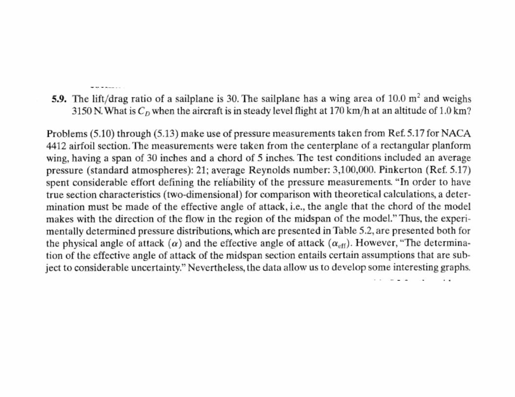
Problems 5.9, 5.10, 5.11, 5.12 due Oct. 22
Problem 5.18 due Oct. 27
QUIZ # 4: Oct. 25


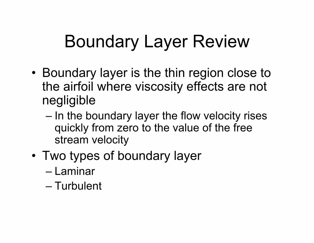
Boundary Layer Review
• Boundary layer is the thin region close to the airfoil where viscosity effects are not negligible– In the boundary layer the flow velocity rises
quickly from zero to the value of the free stream velocity
• Two types of boundary layer– Laminar– Turbulent

Nature of Boundary Layer Transition• A laminar boundary layer is subjected to
numerous disturbances, such as:– Surface roughness– Temperature irregularities– Background noise– Free-stream turbulence
• When disturbances decay or damp out downstream – flow remains laminar
• When disturbances amplify and grow in size downstream– flow becomes turbulent

Boundary Layer Transition on an Airfoil
• Drag coefficient depends on Cf, which depends on Re
• Re affects Cf but also indicates if the boundary layer is laminar or turbulent
• Therefore to calculate drag we must know where the boundary layer transitions from laminar to turbulent

Boundary Layer Transition
• Transition begins at the critical Reynolds number– Ex) for flow over a flat plate transition occurs at a Re
of 500,000• A key concept in transition is to realize the flow
does not transition instantaneously at a single point– Boundary layer shows five distinct phases as it
transitions to fully turbulent flow

TRANSITION - REFERS TO THE CHANGE FROM LAMINAR FLOW TOTURBULENT FLOW
SEPARATION - REFERS THE DEPARTURE OF THE FLOW FROMTHE SURFACE
SEPARATION LOCATION
SLIDES FROM CHAPTER 2 LECTURES
TRANSITION FLOW ISATTACHED,NOT SEPARATED
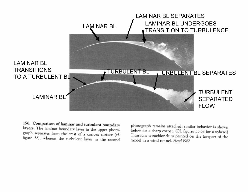
LAMINAR BL
LAMINAR BL SEPARATESLAMINAR BL UNDERGOES TRANSITION TO TURBULENCE
LAMINAR BL
LAMINAR BL TRANSITIONSTO A TURBULENT BL
TURBULENT BL TURBULENT BL SEPARATES
TURBULENTSEPARATEDFLOW
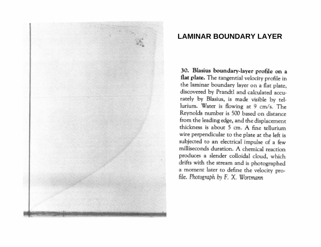
LAMINAR BOUNDARY LAYER

LAMINAR VELOCITY FLUCTUATION
TURBULENT VELOCITY FLUCTUATION
Taken from Karamcheti,
‘Principles of Ideal-Fluid Aerodynamics’
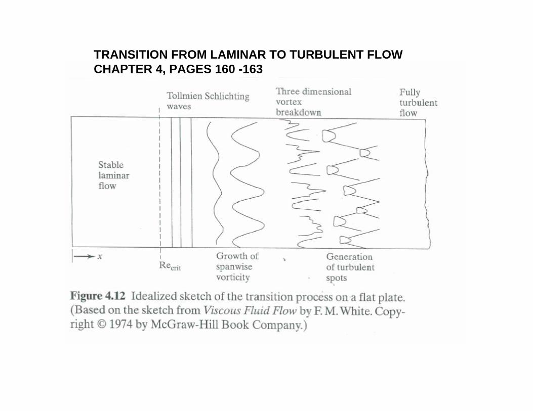
TRANSITION FROM LAMINAR TO TURBULENT FLOWCHAPTER 4, PAGES 160 -163

GROWTH OF UNSTEADY FLUCTUATIONS IN THETRANSITION FROM LAMINAR TO TURBULENT FLOW
UPSTREAM
DOWNSTREAM


What Parameters Affect Transition?
• Surface temperature– Boundary layer thickness decreases as
surface temperature decreases• Cool surface - delays transition
• Suction or blowing at the surface– Blowing – promotes transition– Suction – delays transition
• Free-stream turbulence– Promotes transition

What Parameters Affect Transition?
• Pressure gradient– Favorable - delays transition– Adverse – promotes transition
• Surface roughness– Rough surfaces promote transition
• Compressibility– Mach number
• Critical Reynolds number is usually higher for a compressible flow

SUMMARY OF BOUNDARY LAYER CONDITIONS

EFFECT OF SURFACE ROUGHNESS
(SEE PGS.223-225)
SMOOTH
ROUGH

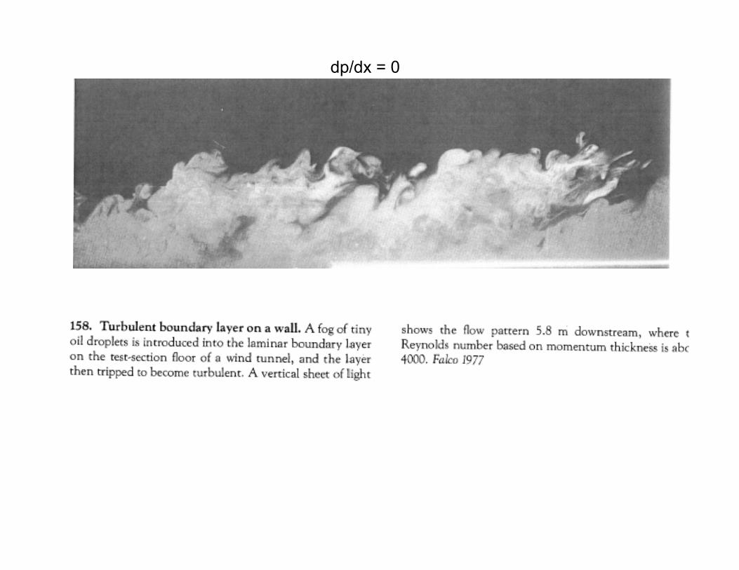
dp/dx = 0
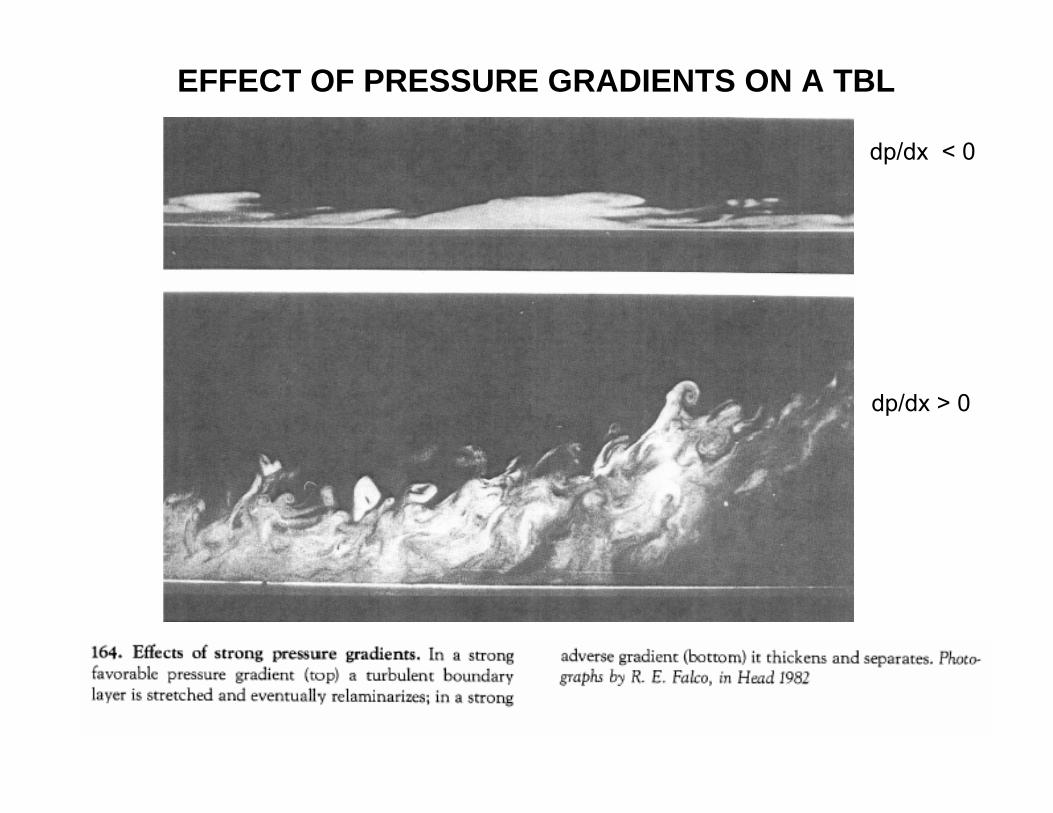
dp/dx < 0
dp/dx > 0
EFFECT OF PRESSURE GRADIENTS ON A TBL

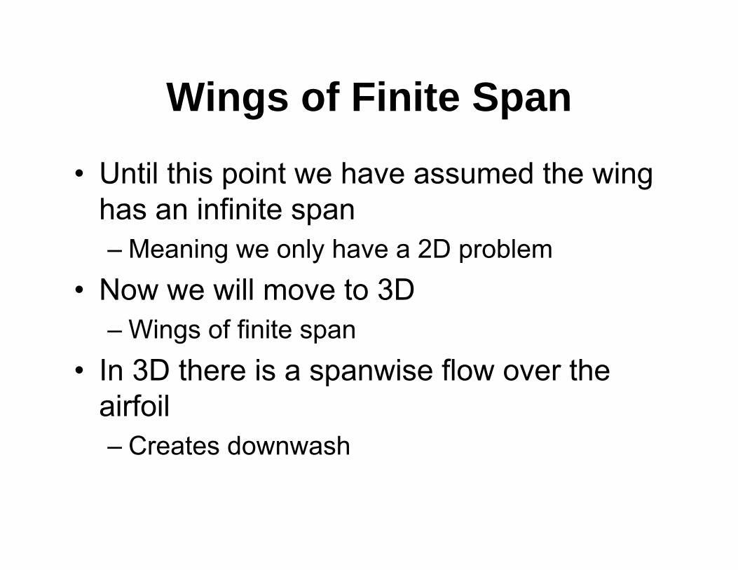
Wings of Finite Span
• Until this point we have assumed the wing has an infinite span– Meaning we only have a 2D problem
• Now we will move to 3D– Wings of finite span
• In 3D there is a spanwise flow over the airfoil– Creates downwash

SINCE THE STRENGTH OF A VORTEX TUBE IN INVISCID FLOW ISCONSTANT, THE CIRCULATION IS CONSTANT ALL ALONG THIS VORTEX
AIRPORT
TRAILING VORTEX SYSTEM
DOWNWASH DUE TOTRAILING VORTICES
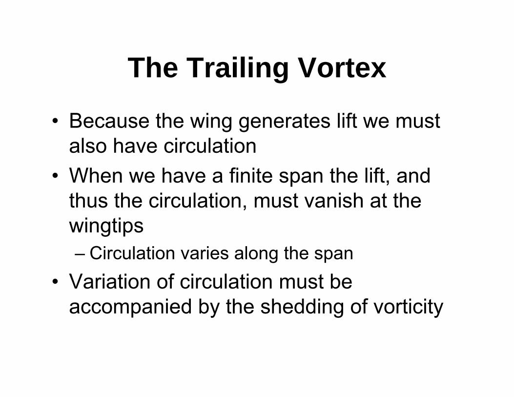
The Trailing Vortex
• Because the wing generates lift we must also have circulation
• When we have a finite span the lift, and thus the circulation, must vanish at the wingtips– Circulation varies along the span
• Variation of circulation must be accompanied by the shedding of vorticity
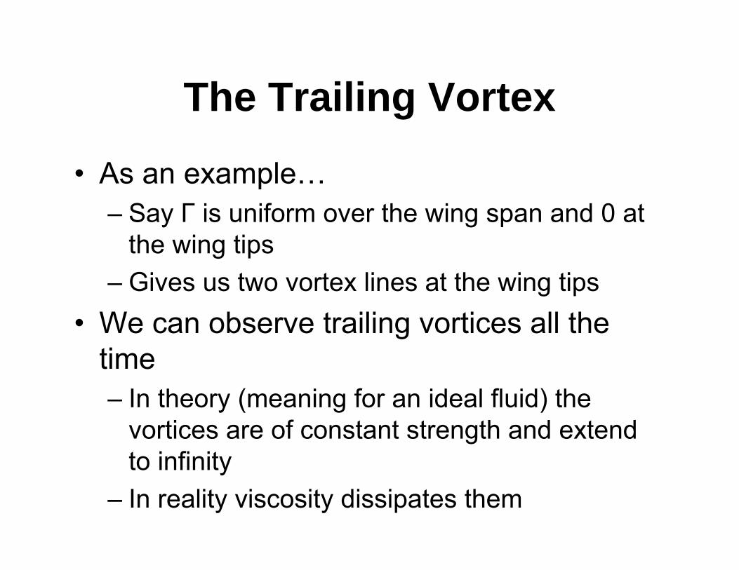
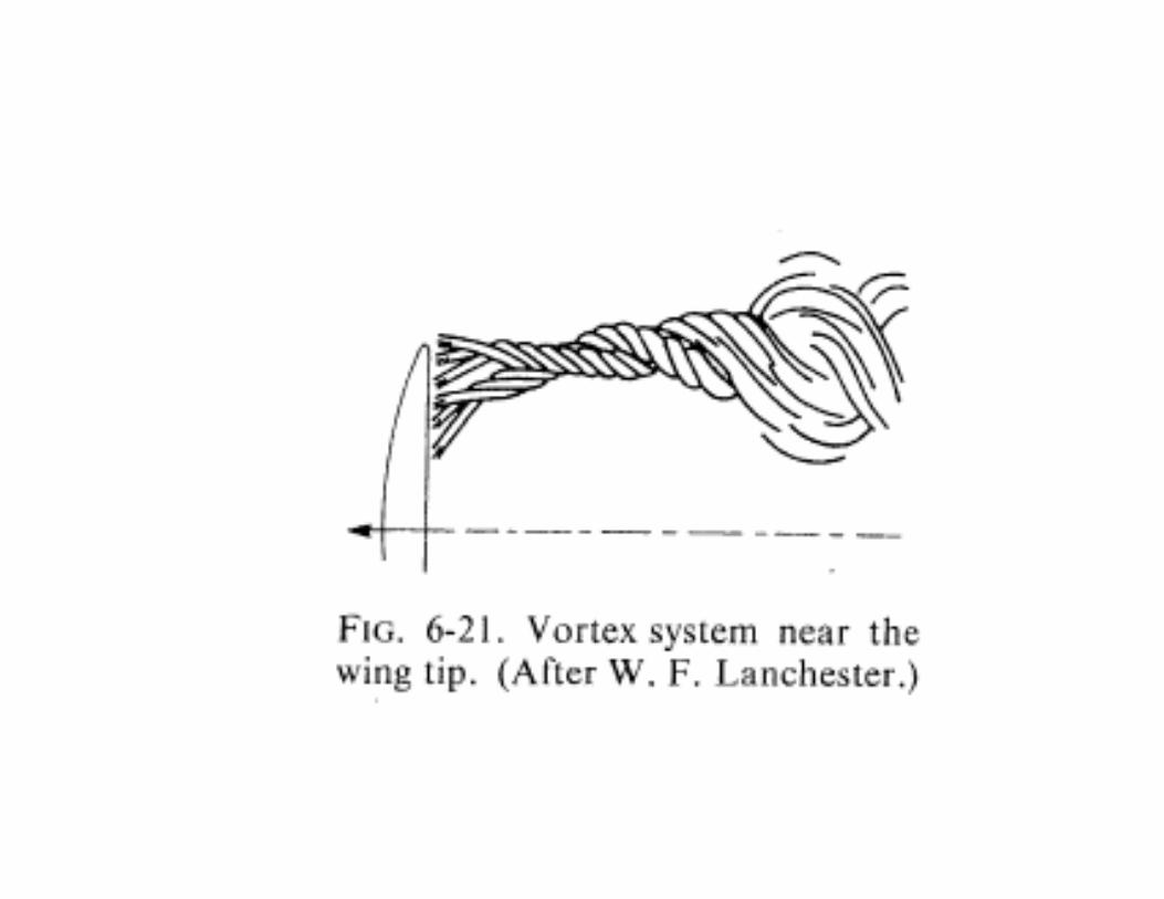
The Trailing Vortex
• As an example…– Say Γ is uniform over the wing span and 0 at
the wing tips– Gives us two vortex lines at the wing tips
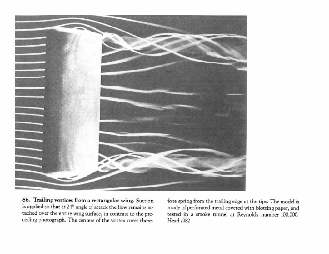
• We can observe trailing vortices all the time– In theory (meaning for an ideal fluid) the
vortices are of constant strength and extend to infinity
– In reality viscosity dissipates them
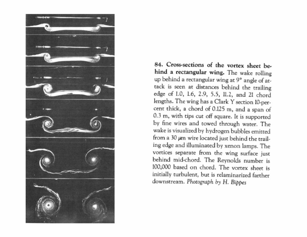


Downwash• Spanwise flow causes distribution of streamwise
vortices– Called the “trailing vortex”
• “Tilts” the fluid so that the effective angle of attack is reduced• Also creates a downwash velocity
• What does this mean?– Lift generated by a wing of finite span is less than the
lift generated by the same wing of infinite span at the same angle of attack
• Also creates vortex (or induced) drag


WINGS OF FINITE SPAN
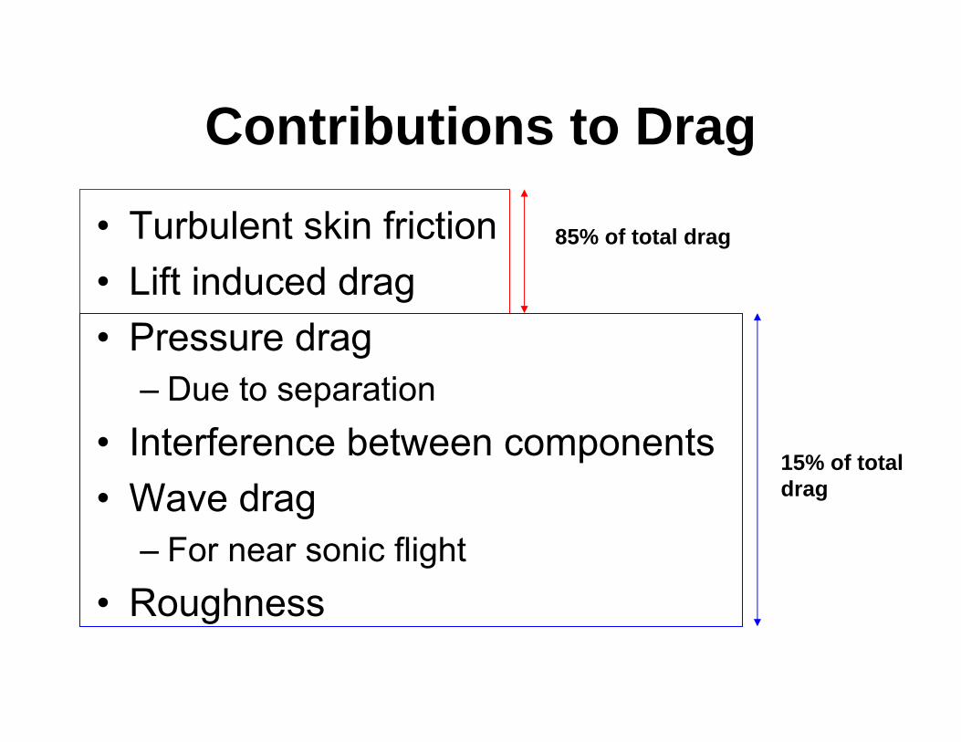
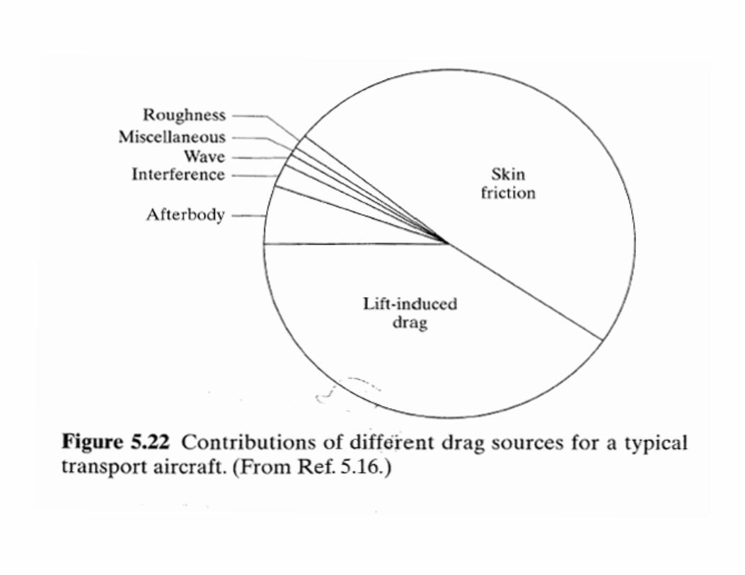
Contributions to Drag
• Turbulent skin friction• Lift induced drag• Pressure drag
– Due to separation• Interference between components• Wave drag
– For near sonic flight• Roughness
85% of total drag
15% of total drag

McCormick, B. W.,“Aerodynamics Aeronauticsand Flight Mechanics,”Wiley, 1995, 2nd Ed, page 151.
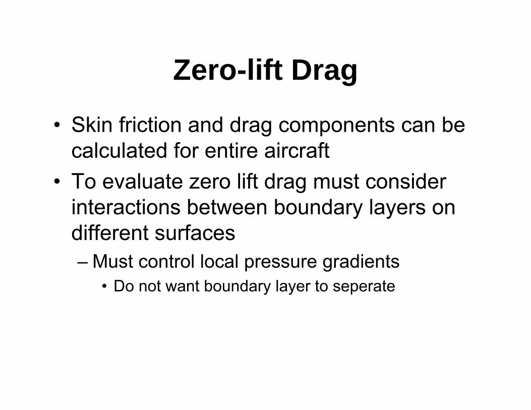
Zero-lift Drag
• Skin friction and drag components can be calculated for entire aircraft
• To evaluate zero lift drag must consider interactions between boundary layers on different surfaces– Must control local pressure gradients
• Do not want boundary layer to seperate


Drag Due to Lift
• The downwash velocity (-w) is proportional to the trailing vortex circulation Γ, which is proportional to the lift L on the airplane.
• The change in angle of attack due to downwash is:ε =(-w)/U∞
• The component of the Lift L that is induced drag is:Dv = Lε ~ L2
• For an unswept low aspect ratio wing we can estimate the drag due to lift as:
eARCkC L
L
22
Γ

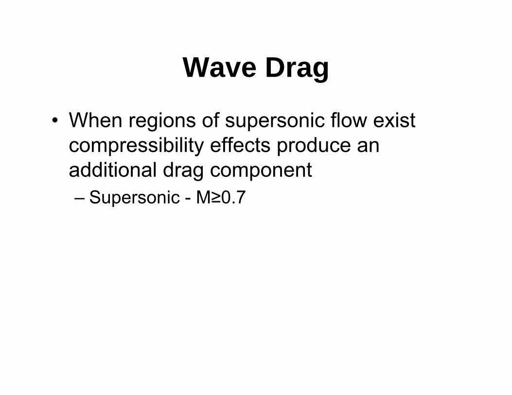
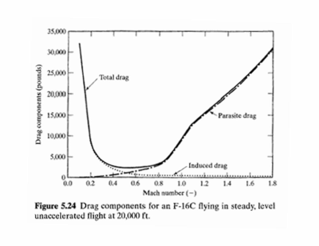
Wave Drag
• When regions of supersonic flow exist compressibility effects produce an additional drag component – Supersonic - M≥0.7

MACH NUMBER EFFECT ON FLOW
(from AOE 5104 notes)

MACH NUMBER EFFECT ON FLOW
(from AOE 5104 notes)

MACH NUMBER EFFECT ON FLOW
(from AOE 5104 notes)

Lift/Drag Ratio
• Several important performance items occur at the maximum lift/drag ratio– Max range of propeller-driven airplanes– Max climb angle for jet-powered airplanes– Max power-off glide ratio
• For both propeller and jet driven airplanes– Max endurance for jet-powered airplanes