Embed Size (px)
Citation preview

1
AntiAnti--Corrosion Steel forCorrosion Steel forPitting corrosion on COTsPitting corrosion on COTs
of crude oil carrierof crude oil carrier
The NSGP-1Nippon Steel’s Green Protect-1

2
The Studies on COT Corrosion in Japan2000 2002 2004 20061998 2000 2002 2004 20061998
Shift to Double Hull Tanker1990~
1999~2002 Panel SR242 Investigation(The Shipbuilding Research Association of Japan)
2002~
2004~NSGP-1 Field Test on actual Vessels
Anti- corrosion steelLaboratory Test
Scientific Research & understandingof the corrosion phenomena
(Over 10 VLCC s)Basis for Anti-corrosion SteelCorrosion test method
NSGP-1
3
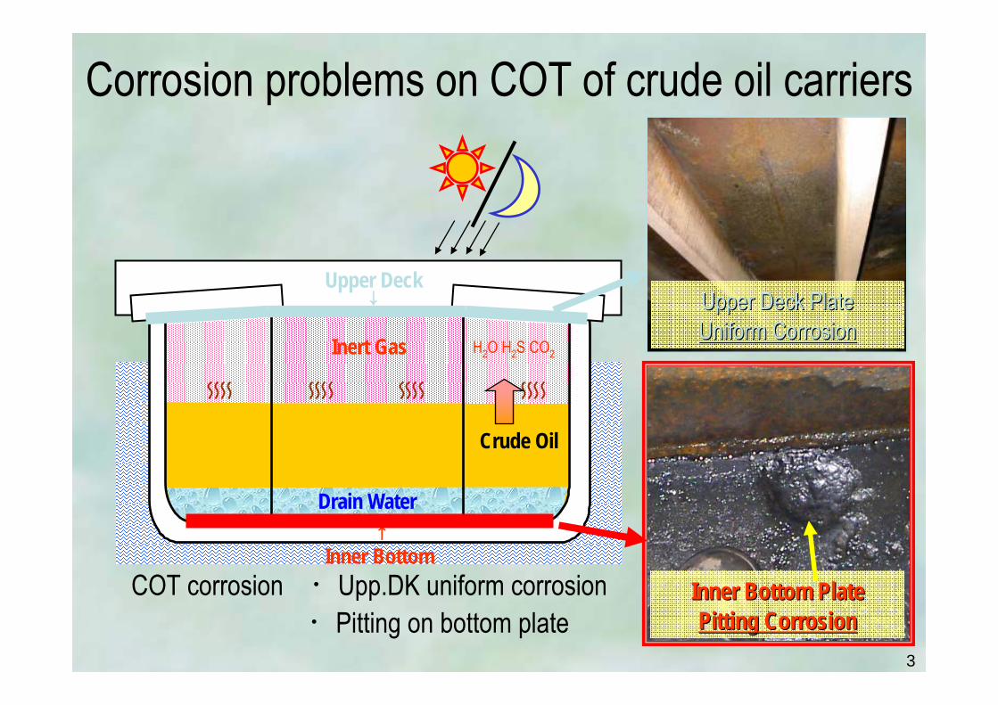
↑Inner Bottom
Inert Gas H2O H2S CO2
Crude Oil
Drain Water
Upper Deck PlateUpper Deck PlateUniform CorrosionUniform Corrosion
Inner Bottom PlateInner Bottom PlatePitting CorrosionPitting Corrosion
Upper Deck↓
Corrosion problems on COT of crude oil carriers
COT corrosion ・Upp.DK uniform corrosion・Pitting on bottom plate

4
Observed Pits on COT bottom plates
・Very Deep : Max. abt.10mm/2.5years・Periodical Repair is Essential
SRSR--242 Result242 Result
5
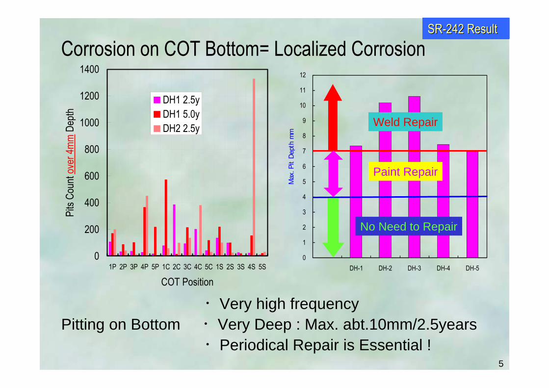
Corrosion on COT Bottom= Localized Corrosion
0
1
2
3
4
5
6
7
8
9
10
11
12
DH-1 DH-2 DH-3 DH-4 DH-5
Max
. Pit
Dept
h m
m
・Very high frequencyPitting on Bottom ・Very Deep : Max. abt.10mm/2.5years
・Periodical Repair is Essential !
0
200
400
600
800
1000
1200
1400
1P 2P 3P 4P 5P 1C 2C 3C 4C 5C 1S 2S 3S 4S 5S
COT Position
Pits
Coun
t ove
r 4mm
Dep
th
DH1 2.5yDH1 5.0yDH2 2.5y
SRSR--242 Result242 Result
No Need to Repair
Paint Repair
Weld Repair

6
How does the pitting corrosion start?

7
Observed insulating resistance of oil coating and tar epoxy painting
Oil coating exists inside of COTOil coating shows high insulating resistance equal to T/E
0
100
200
300
400
500
600
Oil Coating Tar Epoxy
Resis
tance
kΩ・c
Oil coat T/E paint
SensorSensorRSTRST®®
Measurement of resistance
SRSR--242 Result242 Result

8
Cause of oil coating defect-1 Change of oil coating resistance by wetting.
Wetting decreases insulating resistance of oil coat
0
100
200
300
400
500
600
Befor AfterWetting effect
Resis
tance
k Ω・c
m2
SensorSensor
Distilled WaterDistilled Water
SRSR--242 Result242 Result

9
COT No Na T-Fe Fe3+ Cl- SO42- Mg2+ pH H2S
DH-1 13600 2 2 42500 14 ND 7.0 NDDH-3 1S 40000 42 11 48000 1470 ND 7.2DH-3 2P 40000 2.5 1 54000 1350 ND 7.5
Chemical analysis of water sampled from actual COT bottom
Significant quantity of water exists on COT bottomHigh concentration of NaCl solutionNot seawater but Brine from Oil Well
↓Brine damages oil coating resulting pitting CorrosionBrine damages oil coating resulting pitting Corrosion(Existence of Brine : Not depends on crude oil a/o route)
Cause of oil coating defect-1 Change of oil coating resistance by wetting.
SRSR--242 Result242 Result
10
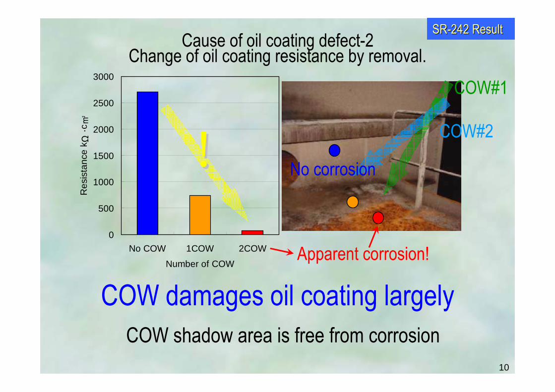
COW damages oil coating largelyCOW shadow area is free from corrosion
0
500
1000
1500
2000
2500
3000
No COW 1COW 2COW
Number of COW
Res
ista
nce
k Ω・c
!!COW#1
COW#2
Apparent corrosion!
Cause of oil coating defect-2 Change of oil coating resistance by removal.
SRSR--242 Result242 Result
No corrosion
11
Short Summary - 1
• Oil coating layer exists inside of COT
• Oil coating layer provides protective effect to corrosion
• Brine a/o COW damages oil coating protective effect
• Pitting starts at the damaged oil coating area
12
How much is the pitting corrosion rate?

13
: Pits over 4mm at 1st inspection (repaired) : Pits less than 2mmless than 2mm at 1st1st inspection (NOT repairedNOT repaired)
: Pits over 4mm at 2nd inspection (repaired)Old pits() did not grow!
New pits() were observed at different points.↓
Pitting growth terminated at the 1st Dock inspection→ Corrosion rate = Pit Depth/Dock Interval
1C
Change of pitting location in plural inspectionsSRSR--242 Result242 Result

14
1P
Change of pitting location in plural inspection-2
: Pits over 4mm at 1st inspection (repaired) : Pits less than 2mmless than 2mm at 1st1st inspection (NOT repairedNOT repaired)
: Pits over 4mm at 2nd inspection (repaired)Old pits() did not grow!
New pits() appear at different points.
SRSR--242 Result242 Result
15
f
0 xX1 X2X3X15
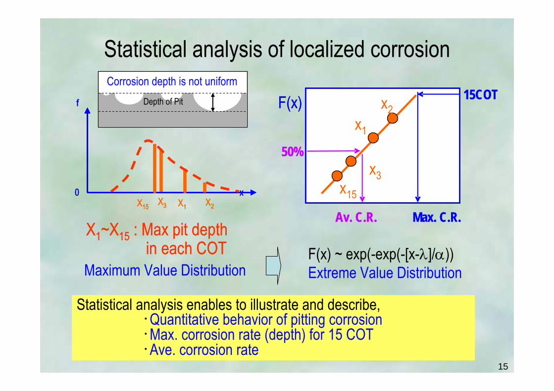
X1~X15 : Max pit depthin each COT
f
0 xX1 X2X3X15
f
0 x
f
0 xX1 X2X3X15
X1~X15 : Max pit depthin each COT
Statistical analysis of localized corrosion
Maximum Value DistributionF(x) ~ exp(-exp(-[x-λ]/α))Extreme Value Distribution
Depth of Pit
Corrosion depth is not uniform
Statistical analysis enables to illustrate and describe,・Quantitative behavior of pitting corrosion・Max. corrosion rate (depth) for 15 COT・Ave. corrosion rate
F(x) x2x1
x3x15
15COT
Max. C.R.
50%
Av. C.R.
F(x) x2x1
x3x15
15COT
Max. C.R.
50%
Av. C.R.

16
・Maximum pitting rate follows statistical distribution・Ship age based corrosion rate : Distribution varies ship by ship →Irrational・Dock Interval Corrosion rate : Same & identical distribution
→ Rational (Corrosion environment cannot differ from ship to ship largely)
1.011.051.111.251.431.6722.53.335
10
202533.350
100
0 1 2 3 4Corrosion Rate mm/year
Ret
urn
Perio
d T
VLD-12.4Years
VLS-12.5Years
VLS-22.5Years
F
99%
98%97%96%95%
90%
80%70%60%50%40%30%20%10%5%1%
0 1 2 3 4Corrosion Rate mm/year
Cum
ulat
ive
Freq
uenc
y F
VLS-17Years
VLD-12.4years
VLS-25years
C.R=Depth/Dock IntervalC.R=Depth/Ship Age
Statistical Distribution of max. pitting corrosion rate (by Statistical extreme value analysis)

17
Brine : NaCl ~10wt.%
Corrosion condition would be reset after Dock inspection→Pitting growth stops at dock cleaning
(1) Under servicing condition
(2) Dock cleaning for inspection
(3) Re-Start of service
(4) Nuclear of new pit
Sludge & Corrosion products
Oil coating
Cleaned Steel Surface = No oil coat
Oil coating ,Sludge & Corrosion productsare cleaned and dried for inspection
Cleaned and dried pits are re-coated by new crude oil
New oil coating = Resetting insulating condition
defect
New defect in oil coating =Nucleation of pitting
New defect : by COW, Brine …..
Discussion on pit growth
Brine : NaCl ~10wt.%
SRSR--242 Result242 Result

18
Pit Growth Stops at a dock(tank cleaning)
Pitting Stops
Pit D
epth
↑Dock Inspection Ship Age
New Pitting starts at new location
Important Basis for Anti-Corrosion Steel

19
Short Summary - 2
• Pitting corrosion rate follows statistical distribution
• Pitting growth duration is dock interval
• Pitting stops at a dock (COT cleaning)

20
What is the pitting environment?

21
Pitting progresses isotropically
keeping constant depth/diameter ratio
If pitting progresses by Galvanic Action…
Irrational to the fact
Shape of Pits
Depth is in linear relation with diameter
0
5
10
15
20
25
30
35
40
45
0 2 4 6 8 10 12Depth mm
Dia
met
er m
m
VLS-B
VLD
VLD-D
VLS-F
・Pitting progresses isotropically with large corrosion rate : abt. 10mm/2.5year・This process hard to think as a result of Galvanic corrosion・Corrosion Environment inside of pit is supposed to be highly aggressive
SRSR--242 Result242 Result

22
An example of observed pH inside of pitspH : Lower than 1.5 → Strong Acid environment
Actual Vessel
pH of PIT inside: <1.5
→→Unfavorable for MIC ((SRB SRB active pH : 6~9active pH : 6~9))
SRSR--242 Result242 Result

23
Max. pitting rate : Very high abt. 3mm/y in actual vessel→ can be explained under strong acid corrosion environment → meets the observed fact : pH inside of pit lower than 1.5
Pitting can be explained as corrosion in strong acid environment
0
1
2
3
4
5
6
7
024681012pH
Corro
sion R
ate m
m/ye
arOxygen consumption ← → H2 evolution
Conventional Steel
Observed pH and Max. corrosion rate

24
Corrosion growth process inside of Pit
【1st Step】Corrosion starts
pH~70.2mm/y
【2nd Step】4< pH <7
pH goes down ~40.2mm/y
【3rd Step】Main corrosion process
pH goes down lower than1.52~4mm/y
Crude Oil
Bottom Plate
Oil Coat DefectBrine (NaCl 10%)
Oil CoatFe2+
↑Fe
Crude Oil
Oil Coat
H+HH++
pH<1.5pH<1.5pH<1.5
Cl-Crude Oil
Oil CoatCl-
Fe2+ + 2H2O → 2H+ + Fe(OH)2
pH>4pH>4pH>4
0
1
2
3
4
5
6
7
024681012pH
Corro
sion R
ate m
m/ye
ar
【2nd Step】
【3rd Step】
【1st Step】
Conventional Steel
Fe2+ + 2H2O → 2H+ + Fe(OH)2
High conc. [Cl-] in Brine
↑Fe (Corrosion)
Cl- ← Balance → H+
in High conc.
Low pH inside of pit↓
25
Short Summary - 3
• Corrosion environment inside of pit is Strong Acid
• pH lower than 1.5 inside of pit

26
Development target and result
27
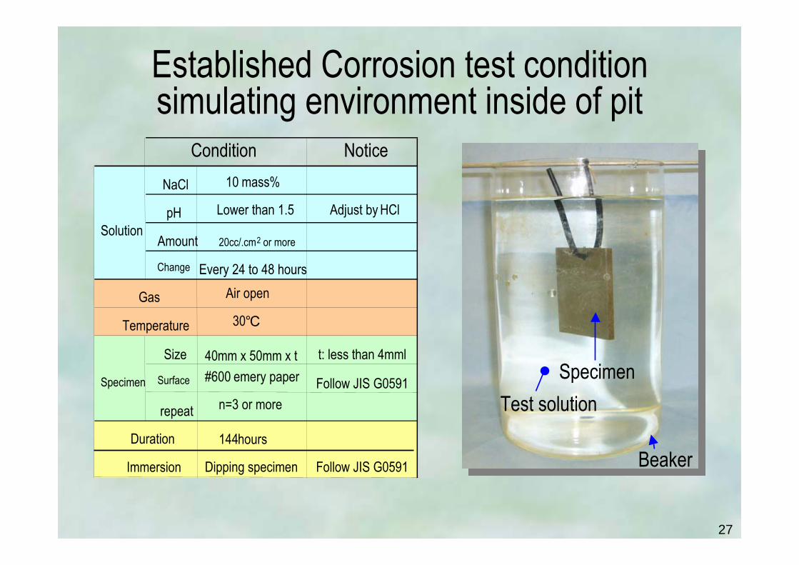
Established Corrosion test condition simulating environment inside of pit
Beaker
SpecimenTest solution
NoticeNaCl 10 mass%
pH Lower than 1.5 Adjust by HCl
Amount 20cc/.cm2 or more
Change Every 24 to 48 hoursAir open
30
Size 40mm x 50mm x t t: less than 4mml
Surface #600 emery paper Follow JIS G0591
repeat n=3 or more
144hours
Dipping specimen Follow JIS G0591Immersion
Gas
Temperature
Condition
Solution
Specimen
Duration

28
0
1
2
3
4
5
6
7
8
0.5 0.6 0.7 0.8 0.9 1 1.1 1.2 1.3 1.4 1.5pH
Corro
sion R
ate m
m/ye
ar
← Conventional Steel
NaCl 10wt.%30
Air OpenStagnant
n=3
NSGP-1 provides superior corrosion resistance (NaCl 10wt.% pH less than 1.5)
Conventional pH=1
NSGP-1 pH=1NSGP-1NSGPNSGP--11

29
Outline of the NSGP-1Newly Developed Anti-corrosion Steel for VLCC COT
A typical example of chemical analysis (mass%)
NSGP-1 established high corrosion resistancewith Least Micro-alloy Elements & ControlNegligible difference to conventional steel
↓No galvanic action with conventional steels & welds
No effect to Physical Properties
C Si Mn P S Al Ti CeqNSGP-1 0.124 0.331
AH32 0.140 0.20 1.09 0.018 0.006 0.031 0.014 0.322IACS Standard ≦ 0.18 ≦ 0.5 0.9~1.6 ≦ 0.035 ≦ 0.035 ≧ 0.02 ≦ 0.02 ≦ 0.36
meets IACS Standard (including all ally elements)
The Chemical composition meets the IACS rules
30
Short Summary - 4
• Developed corrosion test NaCl 10wt.% pH lower than 1.5
• Successful development of NSGP-1 has completed bearing high corrosion resistance with Least Micro-Alloy Elements
(Negligible difference to conventional steel)

31
Property of NSGP-1
・Corrosion Property ・Mechanical Property・Weldability

32
Welding Condition for Property Tests
1000 A, 35 V, electrode speed: 35 m/min heat input: 102.3 kJ/cmPass conditions
50˚ (25˚ each side) root gap :2 mmGrove shapeFAB-1 Metal powder PR2Backing platePF152EFluxUS36(4.8mmφ)Welding Rod

33
0
1
2
3
4
5
6
7
8
0.5 0.6 0.7 0.8 0.9 1 1.1 1.2 1.3 1.4 1.5pH
Corro
sion R
ate m
m/ye
ar
← Conventional Steel
NaCl 10wt.%30
Air OpenStagnant
n=3
NSGP-1 provides superior corrosion resistance (NaCl 10wt.% pH less than 1.5)
Conventional pH=1
NSGP-1 pH=1NSGP-1NSGPNSGP--11

34
NSGP-1 shows NO preferential corrosion around weld (pH=0.8, 336hrs)
NSGP | Weld Metal |NSGP
NSGP-1
100μm
35
0
0.2
0.4
0.6
0.8
1
1.2
1.4
1.6
1.8
2
Matrix Weld
COrro
sion R
ate m
m/ye
ar
ConventionalNSGP-1
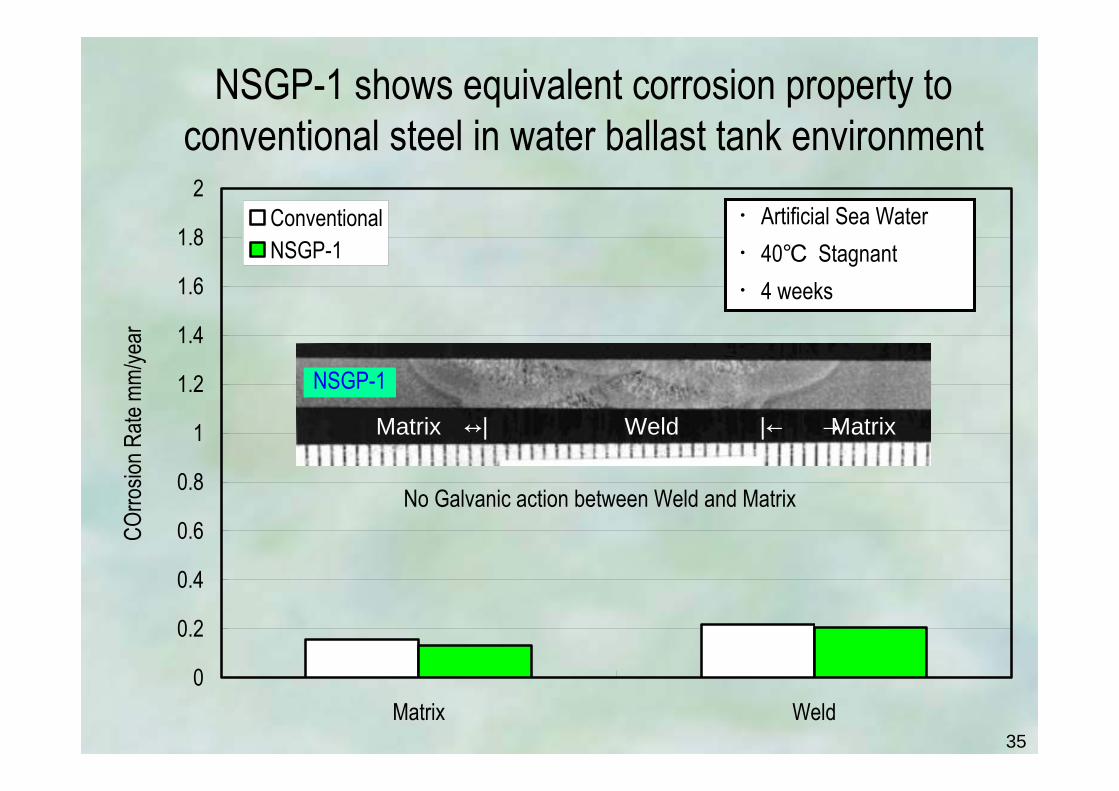
NSGP-1 shows equivalent corrosion property toconventional steel in water ballast tank environment
・Artificial Sea Water・40 Stagnant・4 weeks
← Weld →|← MatrixMatrix →|
NSGP-1
No Galvanic action between Weld and Matrix

36
NSGP-1 provides good weldabilityY-groove cracking test
0
0.1
0.2
0.3
0.4
0.5
0.6
0.7
0.8
0.9
1
0 50 100
Pre-heat Temperature
Crac
k Rat
io %
SurfaceCross sectionRoot
No Crack
0
50
100
150
200
250
300
350
0 20 40 60
Bead Length (mm)
Maxim
um H
ardn
ess(
Hv 1
0kgf
)

37
NSGP-1 provides good fatigue property
100
1000
Stre
ss R
egion
, Δσ(
N/mm
2 )
NS-GP1
YP32,36HT(5 Joints)
Butt Weld Joint (Flat Position)
100
1000
10000 100000 1000000 10000000Number of Cycles to Failure
Stre
ss R
egion
, Δσ(
N/mm
2 )
NS-GP1YP36HT(3 Joints)
Base Metal
10
100
1000
10000 100000 1000000 10000000Number of Cycles to Failure
Stre
ss R
egion
, Δσ(
N/mm
2 )NS-GP1
YP32,36HT(5 Joints)
Fillet Weld T-joint

38
NSGP-1 shows good toughness
0
50
100
150
200
250
300
WeldMetal
Fusion Line
HAZ 1mm
HAZ 3mm
HAZ 5mm
Notch Position
Abso
rbed
Ene
rgy a
t 20
vE20
(J) : Center : 1mm below surface
Standard ≧ 34J
0
50
100
150
200
250
300
WeldMetal
Fusion Line
HAZ 1mm
HAZ 3mm
HAZ 5mm
Notch Position
Abso
rbed
Ene
rgy a
t 20
vE20
(J) : Center : 1mm below surface
Standard ≧ 34J
0
50
100
150
200
250
300
WeldMetal
Fusion Line
HAZ 1mm
HAZ 3mm
HAZ 5mm
Notch Position
Abso
rbed
Ene
rgy a
t 20
vE20
(J) : Center : 1mm below surface
Standard ≧ 34J
0
50
100
150
200
250
300
WeldMetal
Fusion Line
HAZ 1mm
HAZ 3mm
HAZ 5mm
Notch Position
Abso
rbed
Ene
rgy a
t 20
vE20
(J) : Center : 1mm below surface
Standard ≧ 34J
FAB, L direction
Welding Method Shape of groove Heat Input(kJ/cm)
Flux(PFI-52E) Backing Metal(FAB-1)
Welding Material
Table Welding Condition
125Wire(US-36ƒ³6.4)FAB V
0
50
100
150
200
250
300
WeldMetal
Fusion Line
HAZ 1mm
HAZ 3mm
HAZ 5mm
Notch Position
Abso
rbed
Ene
rgy a
t 20
vE20
(J) : Center : 1mm below surface
0
50
100
150
200
250
300
WeldMetal
Fusion Line
HAZ 1mm
HAZ 3mm
HAZ 5mm
Notch Position
Abso
rbed
Ene
rgy a
t 20
vE20
(J) : Center : 1mm below surface
Standard ≧ 34J
0
50
100
150
200
250
300
WeldMetal
Fusion Line
HAZ 1mm
HAZ 3mm
HAZ 5mm
Notch Position
Abso
rbed
Ene
rgy a
t 20
vE20
(J) : Center : 1mm below surface
0
50
100
150
200
250
300
WeldMetal
Fusion Line
HAZ 1mm
HAZ 3mm
HAZ 5mm
Notch Position
Abso
rbed
Ene
rgy a
t 20
vE20
(J) : Center : 1mm below surface
Standard ≧ 34J
FAB, L direction
Welding Method Shape of groove Heat Input(kJ/cm)
Flux(PFI-52E) Backing Metal(FAB-1)
Welding Material
Table Welding Condition
125Wire(US-36ƒ³6.4)FAB V
Welding Method Shape of groove Heat Input(kJ/cm)
Flux(PFI-52E) Backing Metal(FAB-1)
Welding Material
Table Welding Condition
125Wire(US-36ƒ³6.4)FAB V

39
Applied Result of NSGP-1to actual COTs of VLCC

40
NSGP-1 has been applied to actual vessel(All COT bottom have been built with NSGP-1)
NSGPNSGP--11 has been applied to actual vessel(All COT bottom have been built with NSGP-1)
1P
1C
1S
2P
2C
2S
3P
3C
3S
4P
4C
4S
5P
5C
5S
FWD
Ship TAKAMINE (Built by Mitsubishi Heavy Industry)Construction completed with no problem
Applied to all COTs’ bottom platesFor #3 and #4 COTs applied without painting
1st Dock inspection : at 2year 3 month after launching(3P,3S: inspected onboard at 1year9month)
NSGP-1 without Painting
NSGP-1 with Tar-Epoxy painting

41
Conventional
Conventional
NSGP® -1
Conventional
Conventional
NSGP® -1NSGP® -1
NSGP® -1
NSGPNSGP--11 No pit around Drain Hole**Drain Hole : Pits are frequently observed on conventional steel
No Pit observed Frequent deep Pits

42
Weld Line : NO pit marks
NSGP® -1NSGP® -1
NSGPNSGP--11 No Pit around Weld**Weld : No pit has been observed also on conventional steel

43
0 0 0 0 0 00
200
400
600
800
1000
1200
1400
3P 3C 3S 4P 4C 4SCOT Position
Pits
Coun
t ove
r 4mm
Dep
thAt the 1st dock : 2.25 years after building
NSGPNSGP--11 No pit over 4mm depthNo Need to repair, she docked out smoothly.
NSGP® -1NSGP® -1
NSGP-1 brought about actual benefit in actual field for the 1st time

44
Detailed survey on NSGP-1
Finding shallow pits 2 to 4mm depthand
It’s analysis

45
NSGPNSGP--11 Only shallow pits less than 3mm were observed*Repair criteria above 4mm:Paint Repair Above 7mm:Weld Repair
NS-GP120mm NS-GP120mm20mm
↑Pit
←Pit
Depth: 2.8mm Depth: 6.3mm
20mm Conventional20mm20mm Conventional

46
NSGPNSGP--11 Only shallow pits with very low frequency*Repair criteria above 4mm:Paint Repair Above 7mm:Weld Repair
7 7 7 20 4 270
200
400
600
800
1000
1200
1400
3P 3C 3S 4P 4C 4SCOT Position
Pits
Coun
t ove
r 2mm
less
than
4mm
Dep
th
At the 1st Dock( 2.25years after building)
COT built by NS- GP1 without tar epxy painting
NO NEED TO REPAIR
0
2
4
6
8
10
12
3P 3C 3S 4P 4C 4SCOT Position
Obse
rved M
ax pi
t dep
thmm
/at 1s
t Doc
k
COT built by NS-GP1without tar epxy painting
No Need to Repair
At the 1st Dock( 2.25years after building)
0
2
4
6
8
10
12
3P 3C 3S 4P 4C 4SCOT Position
Obse
rved M
ax pi
t dep
thmm
/at 1s
t Doc
k
COT built by NS-GP1without tar epxy painting
No Need to Repair
At the 1st Dock( 2.25years after building)

47
1%5%
10%20%30%40%50%60%70%
80%
90%
95%96%97%98%
99% 100
50352520← 15COT10
5
32.521.61.41.21.11.051.01
0 0.5 1 1.5 2 2.5 3 3.5 4 4.5
Corrosion Rate mm/year
Cumu
lative
Fre
quen
cy F
Retu
ren
Perio
d T
No Repair Repair by Paint Repair by Weld
NSGP-1 Conventional Steels
← 4mm/2.5years
Estimation of Maximum depth
Estimated Maximum Pitting rate & Depth for 15COT : Less than 4mm/2.5y
←AlmostEqualGradient
48
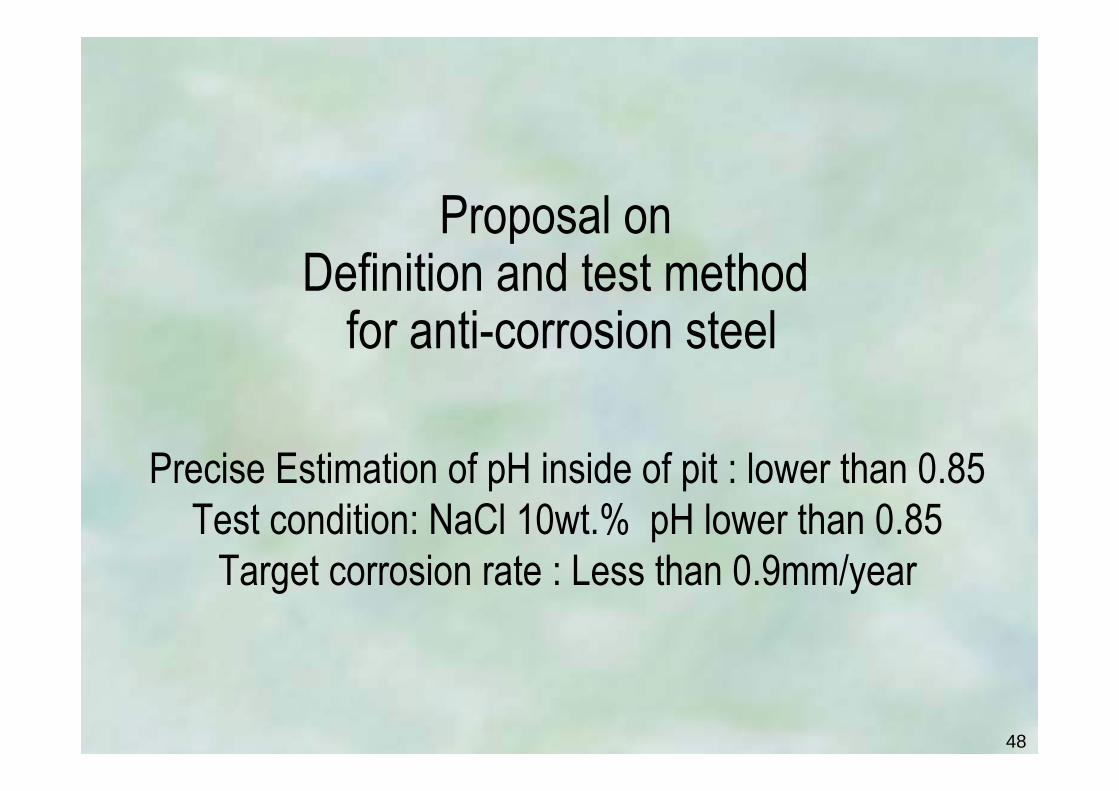
Precise Estimation of pH inside of pit : lower than 0.85Test condition: NaCl 10wt.% pH lower than 0.85
Target corrosion rate : Less than 0.9mm/year
Proposal onDefinition and test method
for anti-corrosion steel

49
Precise estimation of pH inside of PitLower than 0.85
Ship Estimated pHA 1.11B 1.16C 0.93D 0.85E 1.07F 0.94
Ship Max depthmm/2.5years
Max Corrosion Ratemm/year
A 7.50 3.00B 7.06 2.82C 9.51 3.80D 10.57 4.23E 7.90 3.16F 9.40 3.76
A B
CD
EF
0
1
2
3
4
5
6
7
8
0.5 0.6 0.7 0.8 0.9 1 1.1 1.2 1.3 1.4 1.5pH
Corro
sion R
ate m
m/ye
ar
↓ Conventional Steel
Laboratory EvaluationNaCl 10wt.%
30Air OpenStagnant
n=3

50
Established corrosion test for anti-corrosion steelReproducing environment at inside of pits
Beaker
SpecimenTest solution
Notice
NaCl 10 mass%
pH 0.85 Adjust by HCl
Amount 20cc/.cm2 or more
Change Every 24 to 48 hoursAir open
30
Size 40mm x 50mm x t t: less than 4mml
Surface #600 emery paper Follow JIS G0591
repeat n=3 or more
144hours
Dipping specimen Follow JIS G0591Immersion
Gas
Temperature
Condition
Solution
Specimen
DurationBeaker
SpecimenTest solution
Beaker
SpecimenTest solution
Notice
NaCl 10 mass%
pH 0.85 Adjust by HCl
Amount 20cc/.cm2 or more
Change Every 24 to 48 hoursAir open
30
Size 40mm x 50mm x t t: less than 4mml
Surface #600 emery paper Follow JIS G0591
repeat n=3 or more
144hours
Dipping specimen Follow JIS G0591Immersion
Gas
Temperature
Condition
Solution
Specimen
Duration

51
99%
98%
97%96%95%
90%
80%
70%60%50%40%30%20%10%5%
1% 1.01
1.051.11.21.41.6
← 2 Average λ2.53
5
10← 15 COT20253550
100
0 0.5 1 1.5 2 2.5 3Corrosion Rate mm/year
Cumu
lative
Fre
quen
cy F
Retur
n Per
iod T
NSNS--GP1GP1
0.9mm/y
Criterion forAnti-corrosion Steel
Max Corrosion rate for4mm depth for 2.5years in 15COT
Criterion of corrosion rate in Laboratory testfor Repair-Free at 2.5years dock interval
Criterion : less than 0.9mm/year in laboratory test
Need to repair
← Corresponds toLaboratorytest evaluation
← Corresponds toOnboardMax. Depth

52
0
1
2
3
4
5
6
7
8
0.5 0.6 0.7 0.8 0.9 1 1.1 1.2 1.3 1.4 1.5pH
Corro
sion R
ate m
m/ye
ar
← Conventional Steel
NaCl 10wt.%30
Air OpenStagnant
n=3
Proposal to anti-corrosion steel definitionbeing Repair-Free at 2.5years dock interval
(NaCl 10wt.% pH less than 0.85)
NSGP-1NSGPNSGP--11
↓ Less than 0.9mm/yearAcceptable
asAnti-Corrosion Steel
53
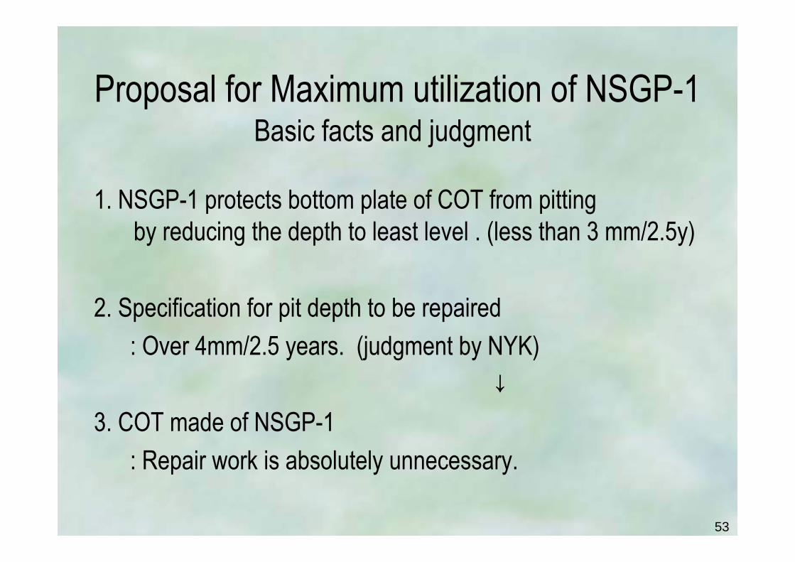
Proposal for Maximum utilization of NSGP-1Basic facts and judgment
1. NSGP-1 protects bottom plate of COT from pitting by reducing the depth to least level . (less than 3 mm/2.5y)
2. Specification for pit depth to be repaired: Over 4mm/2.5 years. (judgment by NYK)
↓3. COT made of NSGP-1
: Repair work is absolutely unnecessary.

54
Proposal for Maximum utilization of NSGP-1Adjusting Dock interval to 2.5 years enables Repair Free
0
2
4
6
8
10
12
0 5 10 15 20 25 30 35Ship Age / years
Corro
sion D
epth
/ mm
No need for maintenance during a whole ship life with NS-GP1
Observed Results
No ne
ed to
Re
pair
Pit Growth Terminatesat Dock inspection
[Found by SR242]
Observed Max. Corrosion Depthwith NS-GP1
Less than 4mm
0
2
4
6
8
10
12
0 5 10 15 20 25 30 35Ship Age / years
Corro
sion D
epth
/ mm
Repair Free during a whole ship life with NSGP-1
Related Facts
No ne
ed to
Re
pair
Pit Growth Stopsat Dock inspection
Observed Max. Corrosion Depthwith NS-GP1
Less than 3mm
NSGP-1 +2.5years dock interval = Repair-FreeDock Inspection
55
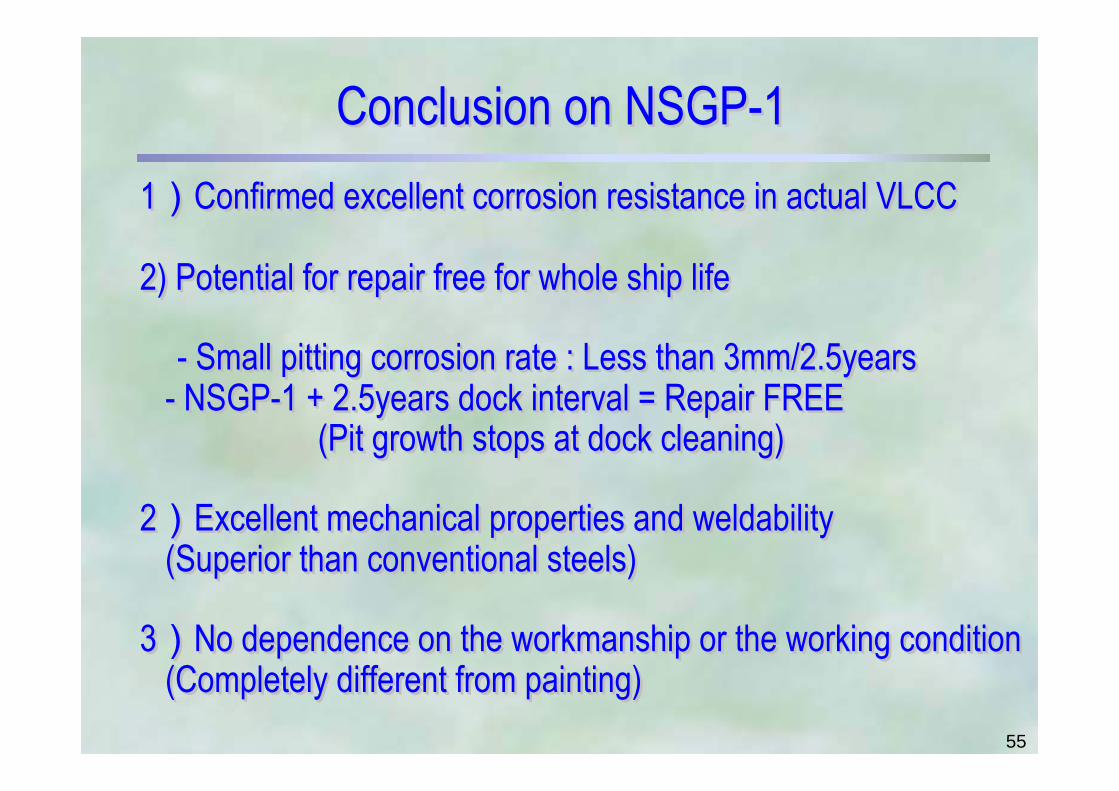
Conclusion on NSGP-1Conclusion on NSGPConclusion on NSGP--111)Confirmed excellent corrosion resistance in actual VLCC
2) Potential for repair free for whole ship life
- Small pitting corrosion rate : Less than 3mm/2.5years- NSGP-1 + 2.5years dock interval = Repair FREE
(Pit growth stops at dock cleaning)
2)Excellent mechanical properties and weldability(Superior than conventional steels)
3)No dependence on the workmanship or the working condition(Completely different from painting)
11))Confirmed excellent corrosion resistance in actual VLCCConfirmed excellent corrosion resistance in actual VLCC
2) Potential for repair free for whole ship life2) Potential for repair free for whole ship life
-- Small pitting corrosion Small pitting corrosion raterate : Less than 3mm/2.5years: Less than 3mm/2.5years-- NSGPNSGP--1 + 2.5years dock interval = Repair FREE1 + 2.5years dock interval = Repair FREE
(Pit growth stops at dock cleaning) (Pit growth stops at dock cleaning)
22))Excellent mechanical properties and Excellent mechanical properties and weldabilityweldability(Superior than conventional steels)(Superior than conventional steels)
33))No dependence on the workmanship or the working conditionNo dependence on the workmanship or the working condition(Completely different from painting)(Completely different from painting)

56
Practical Advantages of the NSGP-1 for Ship OwnerPractical Advantages of the NSGPPractical Advantages of the NSGP--1 for Ship Owner1 for Ship Owner
By using NSGP-1 for COT of crude oil carriers, • Great improvement in the safety and reliability of marine
vessels and in the protection of the global environment• Anti-corrosion coating becomes unnecessary, as do
coating agents and volatile organic compounds.• No need for paint repair and plate replacement.
↓NYK decided to use the NSGP-1 on all new tankers, including 5 VLCCs currently on order.
By using NSGPBy using NSGP--1 for COT of crude oil carriers, 1 for COT of crude oil carriers, •• Great improvement in the safety and reliability of marine Great improvement in the safety and reliability of marine
vessels and invessels and in the protection of the global environmentthe protection of the global environment•• AntiAnti--corrosion coating becomes unnecessary, as do corrosion coating becomes unnecessary, as do
coating agents and volatile organic compounds.coating agents and volatile organic compounds.•• No need for paint repair and plate replacement.No need for paint repair and plate replacement.
↓↓NYK decided to use the NSGPNYK decided to use the NSGP--1 on all new tankers, 1 on all new tankers, including 5 including 5 VLCCsVLCCs currently on order.currently on order.