Embed Size (px)
Citation preview

© 2015 ANSYS, Inc. 1
ANSYS Composite Prepost复合材料建模技术
杜伟卓

© 2015 ANSYS, Inc. 2
Overview
What’s new for Composite Modeling in R16
Renamed Objects
Enhancements in ACP
Enhancements in Mechanical
Where to find more information
Q & A
© 2015 ANSYS, Inc. 3
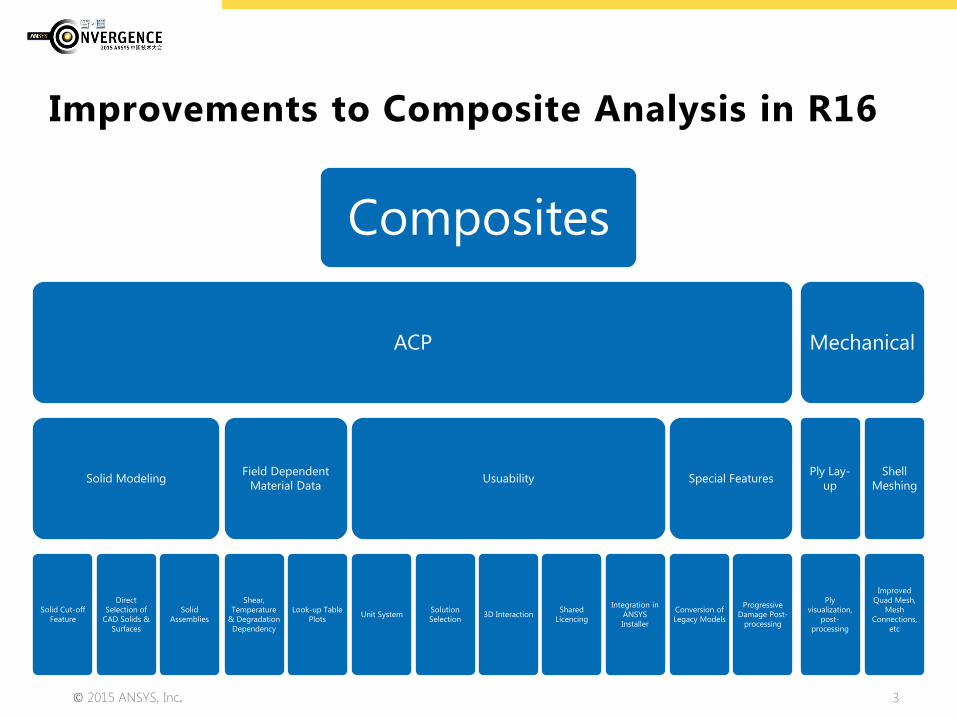
Improvements to Composite Analysis in R16
Composites
ACP
Solid Modeling
Solid Cut-off Feature
Direct Selection of
CAD Solids & Surfaces
Solid Assemblies
Field Dependent Material Data
Shear, Temperature
& Degradation Dependency
Look-up Table Plots
Usuability
Unit System Solution Selection 3D Interaction Shared
Licencing
Integration in ANSYS Installer
Special Features
Conversion of Legacy Models
Progressive Damage Post-
processing
Mechanical
Ply Lay-up
Ply visualization,
post-processing
Shell Meshing
Improved Quad Mesh,
Mesh Connections,
etc

© 2015 ANSYS, Inc. 4
• New Feature Names
• Sampling Element = Sampling Point
• Rule = Selection Rule
• Modeling Ply Group = Modeling Group
• Oriented Element Set = Oriented Selection Set
Renaming of Objects

© 2015 ANSYS, Inc. 5
Solid Modeling
Solid Cut-off Feature
Direct Selection of CAD Solids & Surfaces
Solid Assemblies
© 2015 ANSYS, Inc. 6
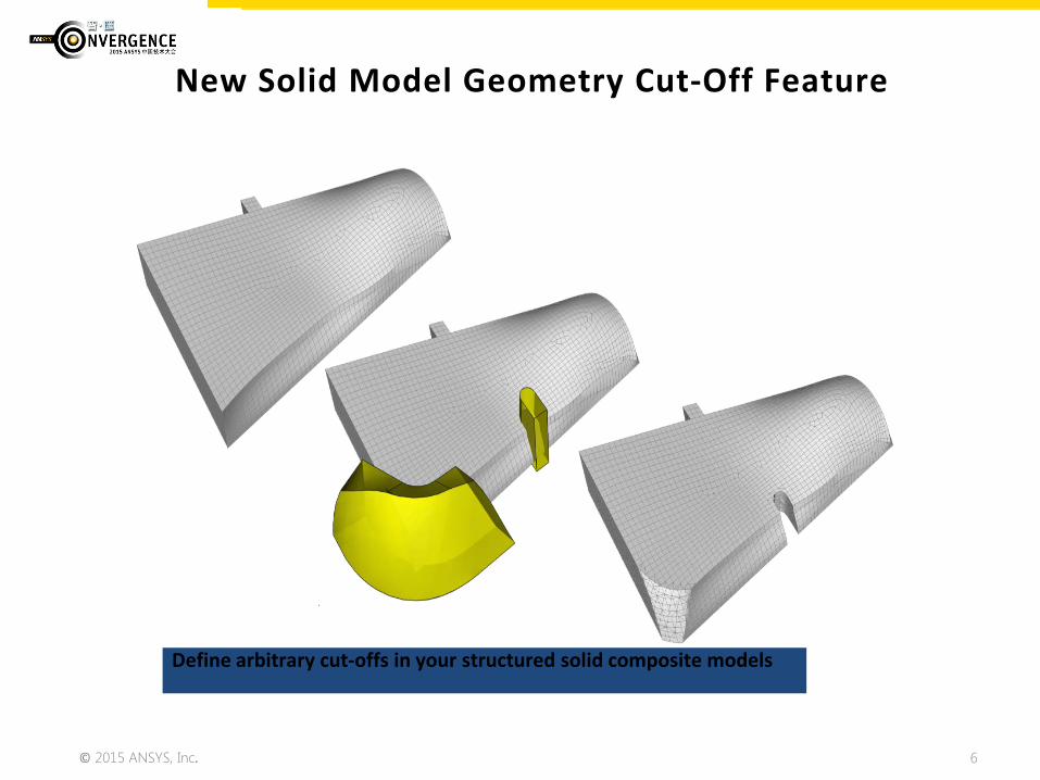
New Solid Model Geometry Cut-Off Feature
Define arbitrary cut-offs in your structured solid composite models
© 2015 ANSYS, Inc. 7
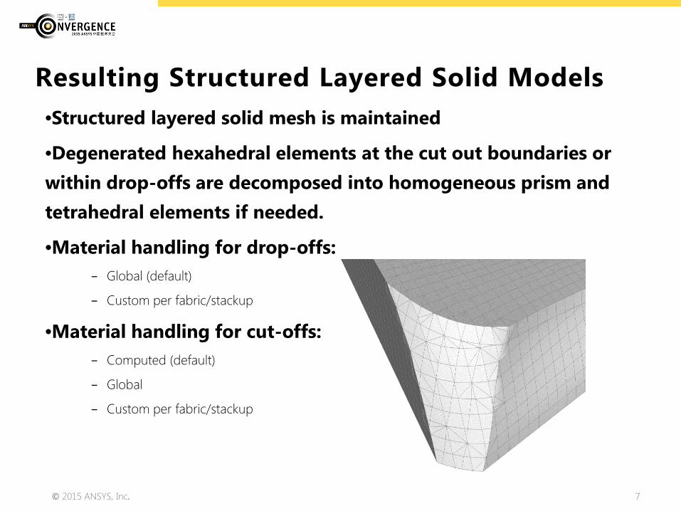
•Structured layered solid mesh is maintained
•Degenerated hexahedral elements at the cut out boundaries or within drop-offs are decomposed into homogeneous prism and tetrahedral elements if needed.
•Material handling for drop-offs: − Global (default)
− Custom per fabric/stackup
•Material handling for cut-offs: − Computed (default)
− Global
− Custom per fabric/stackup
Resulting Structured Layered Solid Models
© 2015 ANSYS, Inc. 8
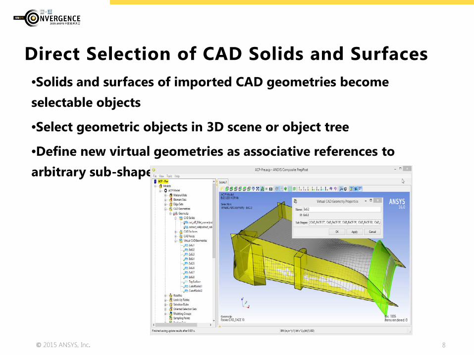
•Solids and surfaces of imported CAD geometries become selectable objects
•Select geometric objects in 3D scene or object tree
•Define new virtual geometries as associative references to arbitrary sub-shapes of the imported geometry
Direct Selection of CAD Solids and Surfaces

© 2015 ANSYS, Inc. 9
•Mechanical R16.0 takes care of renumbering entities automatically when assembling (composite) parts
•The renumbering can be disabled per composite cell
Automatic Renumbering in Mechanical Composite Assemblies
© 2015 ANSYS, Inc. 10
Field Dependent Material Data
Shear, Temperature & Degradation
Factor Dependent Material Data
Look-up Table Plots
© 2015 ANSYS, Inc. 11
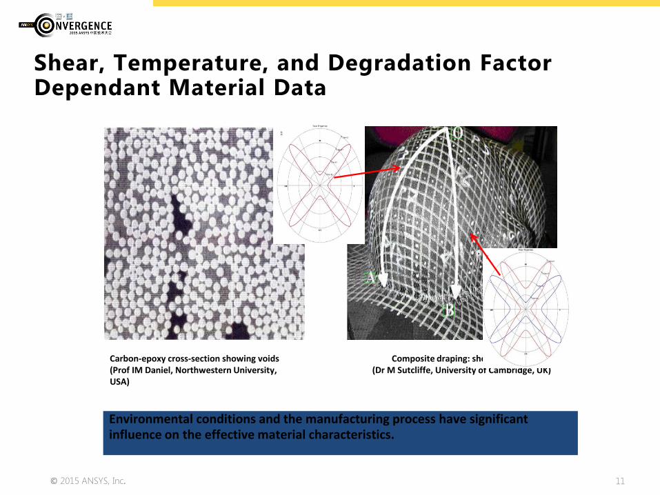
Shear, Temperature, and Degradation Factor Dependant Material Data
Environmental conditions and the manufacturing process have significant influence on the effective material characteristics.
Carbon-epoxy cross-section showing voids (Prof IM Daniel, Northwestern University, USA)
Composite draping: shear and wrinkling (Dr M Sutcliffe, University of Cambridge, UK)
© 2015 ANSYS, Inc. 12
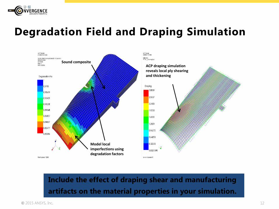
Include the effect of draping shear and manufacturing artifacts on the material properties in your simulation.
Degradation Field and Draping Simulation
Model local imperfections using degradation factors
Sound composite ACP draping simulation reveals local ply shearing and thickening
© 2015 ANSYS, Inc. 13
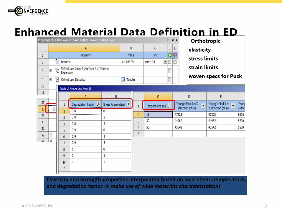
Enhanced Material Data Definition in ED
Elasticity and Strength properties interpolated based on local shear, temperature, and degradation factor → make use of wide materials characterization!
Orthotropic
elasticity
stress limits
strain limits
woven specs for Puck

© 2015 ANSYS, Inc. 14
How to Define a Degradation Field
Using 3D Look-up Tables based on CSV-files allows for full flexibility.
Degradation of 1 = sound
Degradation of 0 = fully degraded
© 2015 ANSYS, Inc. 15
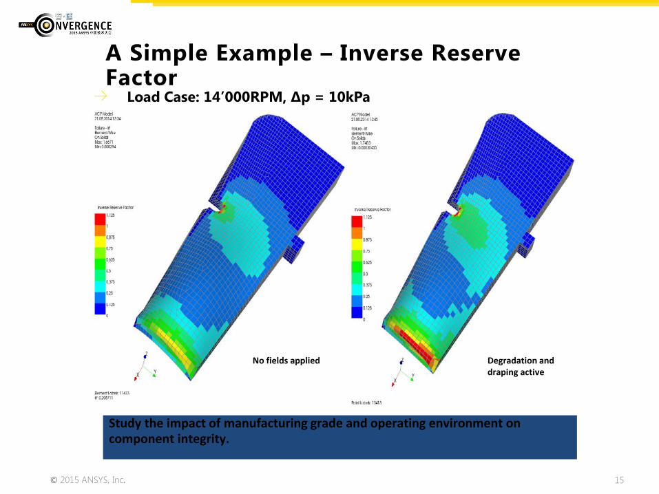
Load Case: 14’000RPM, Δp = 10kPa
A Simple Example – Inverse Reserve Factor
Study the impact of manufacturing grade and operating environment on component integrity.
No fields applied Degradation and draping active
© 2015 ANSYS, Inc. 16
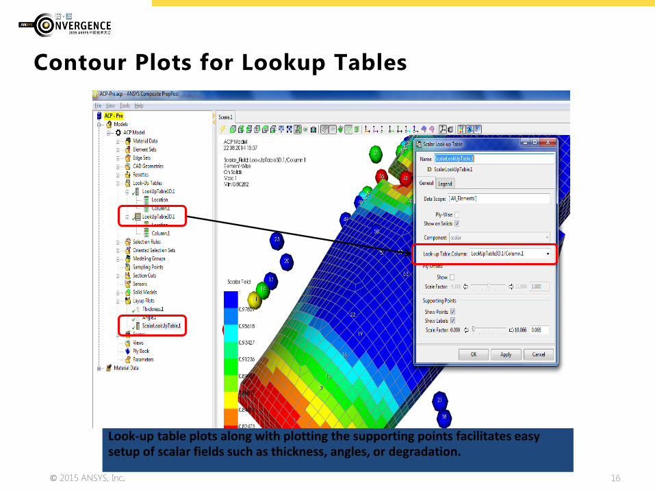
Contour Plots for Lookup Tables
Look-up table plots along with plotting the supporting points facilitates easy setup of scalar fields such as thickness, angles, or degradation.
© 2015 ANSYS, Inc. 17
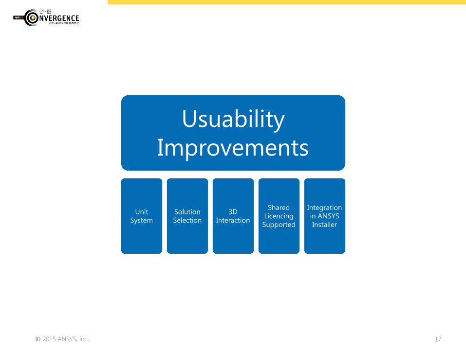
Usuability Improvements
Unit System
Solution Selection
3D Interaction
Shared Licencing Supported
Integration in ANSYS Installer

© 2015 ANSYS, Inc. 18
•User can now freely choose unit system in ACP
•ACP remembers the last unit system used (same logic as Mechanical)
Enhanced Unit System Handling for Composite WB Projects
© 2015 ANSYS, Inc. 19
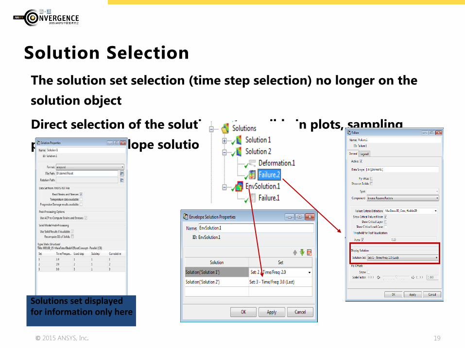
The solution set selection (time step selection) no longer on the solution object
Direct selection of the solution set possible in plots, sampling points and envelope solution.
Solution Selection
Solutions set displayed for information only here

© 2015 ANSYS, Inc. 20
Enhanced 3D Interaction
Camera rotation similar to Mechanical Red dot indicates center
Probe can be deactivated with “Probe Values on Hover” button in toolbar
Deformed Shape is now set for the scene and not for individual plots
© 2015 ANSYS, Inc. 21
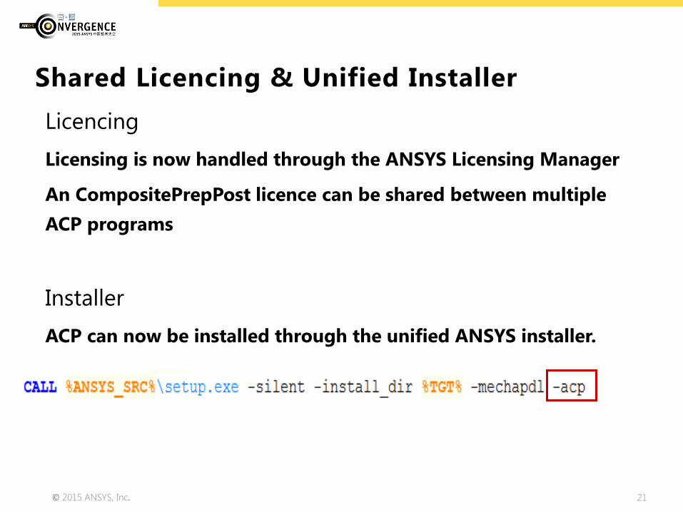
Licencing Licensing is now handled through the ANSYS Licensing Manager
An CompositePrepPost licence can be shared between multiple ACP programs
Installer ACP can now be installed through the unified ANSYS installer.
Shared Licencing & Unified Installer

© 2015 ANSYS, Inc. 22
Special Features
Conversion of Legacy Models
Progressive Damage Post-
processing

© 2015 ANSYS, Inc. 23
New Conversion of Legacy MAPDL Composite Models to WB/ACP Projects
1. Import MAPDL model into ACP as postprocessing
model
2. Set model unit system
3. Save H5 file of layup
4. Create new WB project
5. Define materials in Engineering Data. Or export
materials from ACP Post in xml and import in
Engineering Data
6. Create shell mesh by using existing mesh
(External Model) or create new mesh in
Mechanical
7. Import layup from H5 file in ACP-Pre
Limitation: Shell model only

© 2015 ANSYS, Inc. 24
New Postprocessing of Progressive Damage in ACP Post
Post-process possibilities: • Max damage per element / composite stack • Ply wise damage
© 2015 ANSYS, Inc. 25
Mechanical
Ply Lay-up Shell Meshing
© 2015 ANSYS, Inc. 26
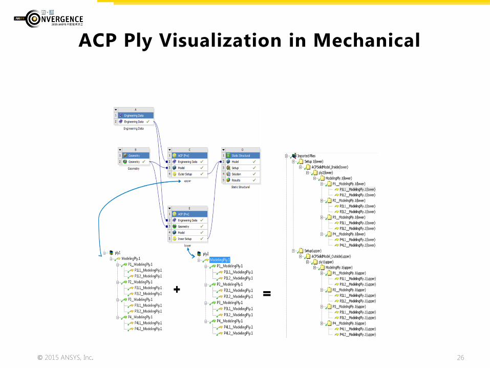
ACP Ply Visualization in Mechanical
© 2015 ANSYS, Inc. 27
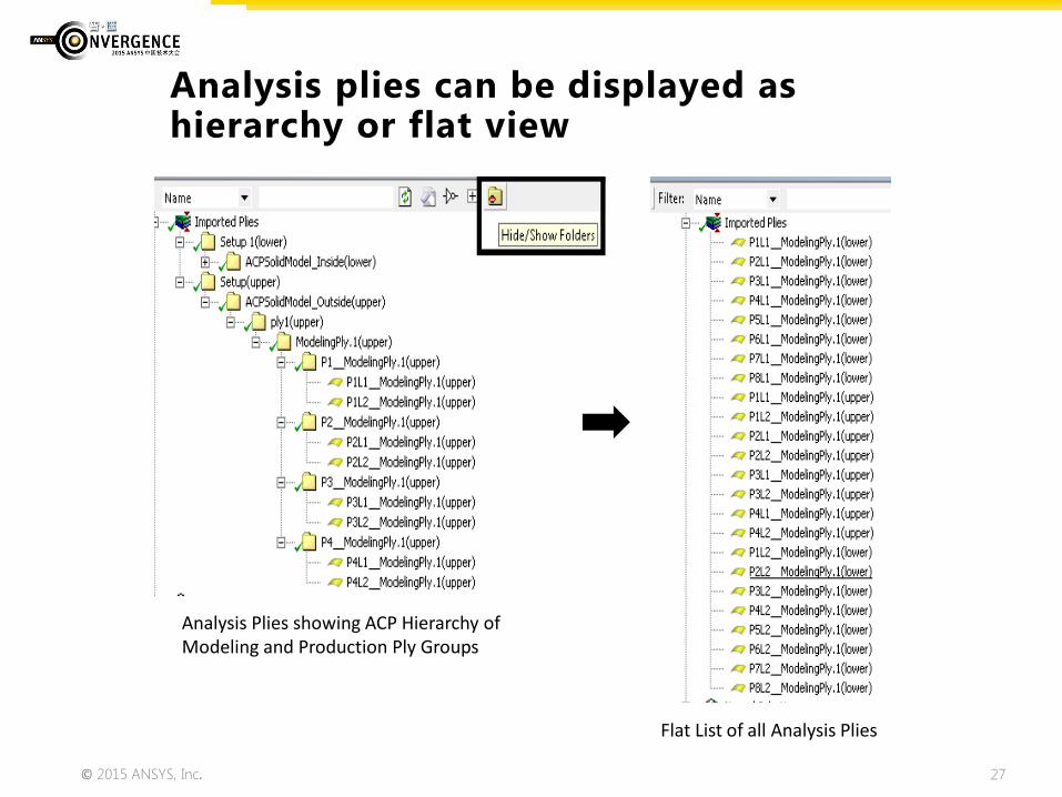
Analysis plies can be displayed as hierarchy or flat view
Analysis Plies showing ACP Hierarchy of Modeling and Production Ply Groups
Flat List of all Analysis Plies
© 2015 ANSYS, Inc. 28
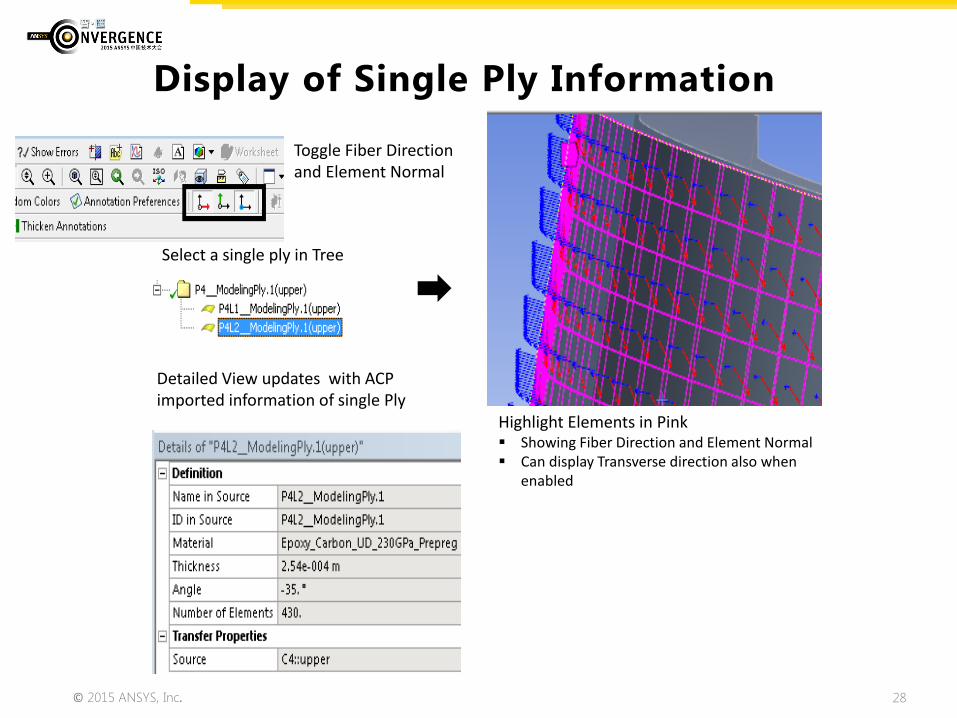
Display of Single Ply Information
Select a single ply in Tree
Highlight Elements in Pink Showing Fiber Direction and Element Normal Can display Transverse direction also when
enabled
Toggle Fiber Direction and Element Normal
Detailed View updates with ACP imported information of single Ply

© 2015 ANSYS, Inc. 29
Display of Fiber Stresses by Ply or by Layer
Ability to change Position in a Ply Pick a Ply and change CSYS
Use arrow key to navigate between ply results
© 2015 ANSYS, Inc. 30
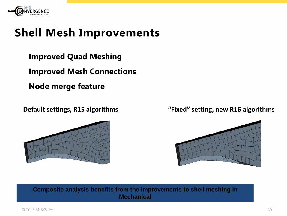
Shell Mesh Improvements
Improved Quad Meshing
Improved Mesh Connections
Node merge feature
Default settings, R15 algorithms “Fixed” setting, new R16 algorithms
Composite analysis benefits from the improvements to shell meshing in Mechanical
© 2015 ANSYS, Inc. 31
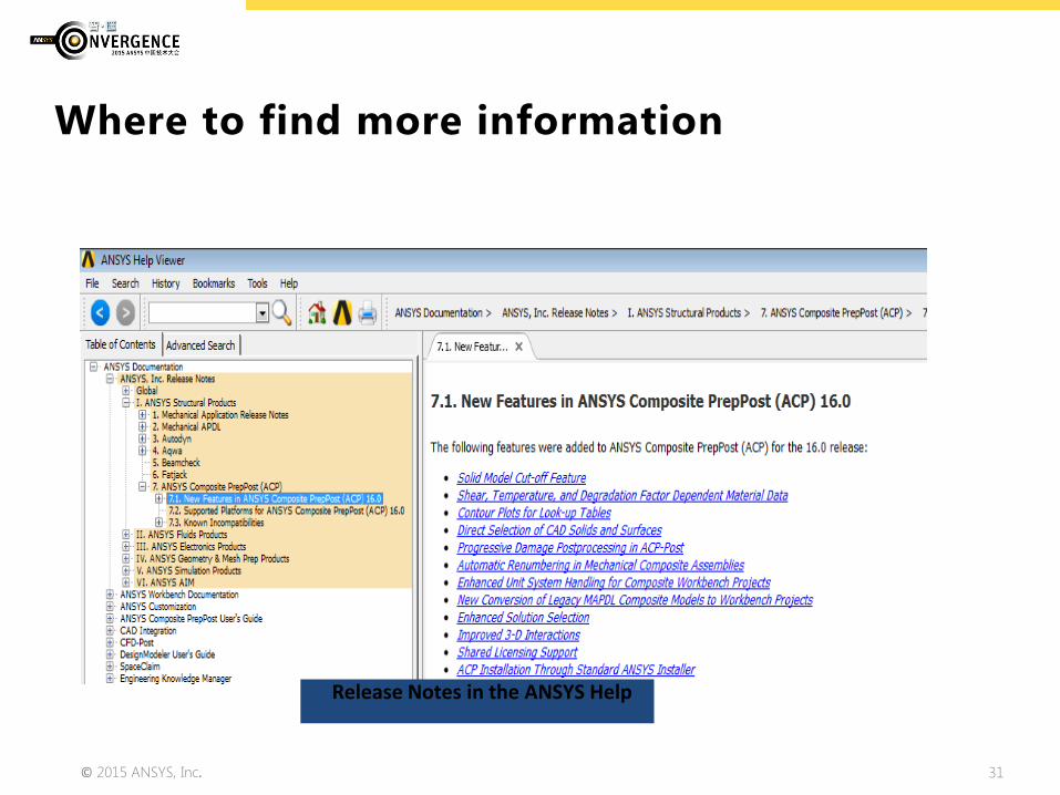
Where to find more information
Release Notes in the ANSYS Help

© 2015 ANSYS, Inc. 32
Tutorials & Training Material
Tutorials in the examples folder of the installation directory and on the customer portal.
Training material in the process of being updated but not available yet.
There will be an ACP R16.1 release, with notable performance enhancements.

© 2015 ANSYS, Inc. 33
Thank you