Embed Size (px)
Citation preview
6th BETA CAE International Conference
ANSA SCRIPTING FOR AUTOMATED PEDESTRIAN MARKING AND SIMULATION INPUT 1Yogesh Upreti 1Matthias Erzgraeber 2Thanassis Fokylidis 1Adam Opel AG, Germany, 2BETA CAE Systems S.A., Greece KEYWORDS – European Consumer Metrics pedestrian marking ANSA python scripting ANSA PedSafety module Automated transformation creation ABSTRACT – For fast project framing to production process in automotive industry, there is a huge requirement to reach from CAD design release of particular vehicle to respective simulation results as soon as possible. Reaching this goal efficiently requires converting manual work involved in this process to automated work to a large extent. Current European Consumer Metrics v8.0 pedestrian protection testing protocols requires up to five different type of load-case simulation done, on same vehicle, at each development stage. This means, for a typical small size vehicle, to prepare approximately 160 head (child and adult), 11-13 upper leg and same amount of lower leg simulation to be prepared. This paper discusses an example of how to use ANSA python scripting module for highly automating the process to go from vehicle outer surface information over to pedestrian related field marking and then to transformations for each testing location based on test type. Further on this paper present an example toolbox for pedestrian marking and transformation creation based on ANSA python programming module (especially PedSafety module).

6th BETA CAE International Conference
1. INTRODUCTION
In November 2012, when European Consumer Metrics pedestrian test protocol changed from field assessment approach to GRID assessment, deliverables for simulation assessment changed drastically from results on 24 locations to approximate 160-180 locations. With the GRID approach the strategy for overall point calculation also changed from worst case location of each field, to each location contributing to overall point score, which made simulation results on multiple locations mandatory.
The GRID approach not only requires to perform simulation in each location, but also it needs to perform proper geometry checks for vehicle marking, calculating number of GRID locations, determining locations according to protocol, dividing locations between adult and child area and last but not least determination of default green and default red locations based on vehicle geometry.
AS test areas are defined by geometries, Pedestrian Tool in ANSA provides vehicle marking facility for different protocols (European, Japan, GTR etc.). Attached to this, is PedSafety module in ANSA Python Scripting, which can be utilized to perform all functions from Pedestrian Tool, like vehicle marking, test device positioning, etc. and ANSA Scripting can be used to customized steps in between, according to required deliverables.
This paper discusses ANSA Python Scripting’s PedSafety module to provide a Toolbox similar to Pedestrian Tool, which allows small customization in procedure to improve and automatize engineer’s work of vehicle outer surface geometry assessment and testing device positioning for pedestrian simulation. Along with that this paper also discusses capabilities of ANSA Pedestrian Tool for Consumer Metrics and Regulatory marking.
All the capabilities discussed in this paper are based on, ANSA 15.2.1 as the latest release version. Not all the capabilities are available, one to one, in earlier ANSA releases, however later ANSA releases will contain discussed facilities.
2. PEDESTRIAN MARKING
Analysis of a vehicle for European Consumer Metrics pedestrian passive safety requirements,
can be divided into two different sets of information. First is to mark the vehicle with different set of lines that are used to define Head, Upper Leg and Lower Leg fields (Fig. 1) according to the
Fig. 1: Pedestrian Marking Lines
6th BETA CAE International Conference
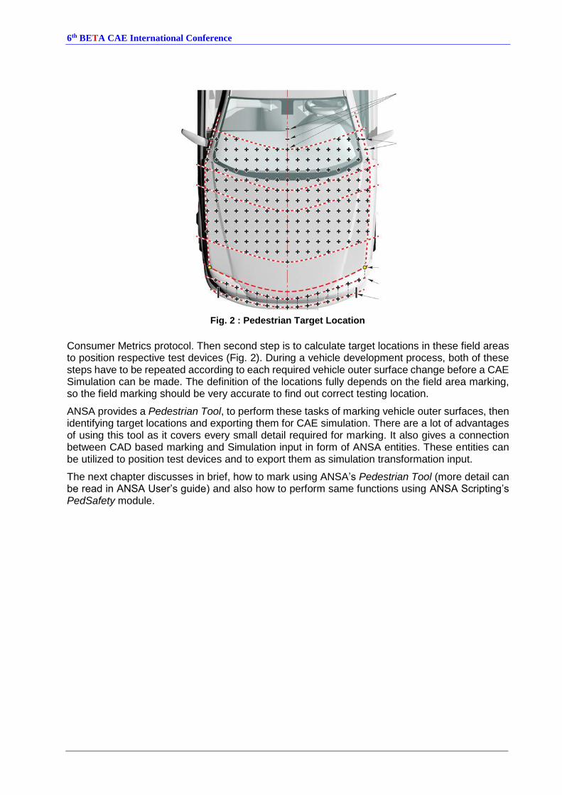
Consumer Metrics protocol. Then second step is to calculate target locations in these field areas to position respective test devices (Fig. 2). During a vehicle development process, both of these steps have to be repeated according to each required vehicle outer surface change before a CAE Simulation can be made. The definition of the locations fully depends on the field area marking, so the field marking should be very accurate to find out correct testing location.
ANSA provides a Pedestrian Tool, to perform these tasks of marking vehicle outer surfaces, then identifying target locations and exporting them for CAE simulation. There are a lot of advantages of using this tool as it covers every small detail required for marking. It also gives a connection between CAD based marking and Simulation input in form of ANSA entities. These entities can be utilized to position test devices and to export them as simulation transformation input.
The next chapter discusses in brief, how to mark using ANSA’s Pedestrian Tool (more detail can be read in ANSA User’s guide) and also how to perform same functions using ANSA Scripting’s PedSafety module.
Fig. 2 : Pedestrian Target Location

6th BETA CAE International Conference
3. VEHICLE MARKING IN ANSA
Using the procedure described in ANSA User Guide section 23.6.1, reference line generation can
be done in few steps. First the user selects which protocol and area to use, defines different areas of vehicle in form of entity sets, defines ground line (using single point coordinate or two points for an inclined ground), selects which protocol is to be followed for marking and finally vehicle marking can be done using “Mark” button (Fig. 3)
To perform same using ANSA Scripting module, as the first step, the user needs to collect the sets for different areas using:
set = ansa.base.PickEntities(ansa.constants.LSDYNA,("SET",))
Then user has to specify ground position, type of protocol, different angle information for marking lines etc. to the PedSafety module using:
pedsafety = base.PedSafety(..all ~23 parameters..1)
Finally the vehicle can be marked using
check = pedsafety.mark()
This function marks all the lines required according to the parameters defined, and marks the vehicle outer surface according to parameters specified.
1 Parameters used for PedSafety can be checked in scripting help in ANSA Scripting Help.
Fig. 3 : ANSA Pedestrian Tool marking steps

6th BETA CAE International Conference
As a result, user gets the vehicle outer surface marked as shown in Fig. 4. With the vehicle
marking, ANSA also generates impact locations for each testing type. These locations are checked according to European Consumer Metrics protocol for all tolerances and eliminations.
There are a lot of preparation and steps that ANSA does as the part of marking. The next chapter discusses the advantages of using ANSA for marking according to European Consumer Metrics protocol.
Fig. 4 : Result of PedSafety.mark() function

6th BETA CAE International Conference
4. ADVANTAGES OF MARKING IN ANSA
While marking the vehicle for European Consumer Metrics v8.0, ANSA takes care of following:
4.1. Head Impact Area
Deleting the impact location which are cut off by Side Reference Line offset (Fig. 5)
Filling up gaps between hood and windscreen with horizontal tapes (Fig. 6)
Calculating the Bonnet Rear Reference Line with a sphere (Fig. 7)
Fig. 6: Stripes to fill up area in Head (Left) and IBRL (Right)
Fig. 5: Deleted Points Head Area (50 mm from SRL)
Fig. 7: BRRL calculation using sphere

6th BETA CAE International Conference
Dividing head area in Adult and Child Head zones according to the protocol,
Using a circular template to mark BRRL and SRL transition accurately (Fig. 8)
4.2. Upper Leg Area
Filling up openings in bumper parts to project the Internal Bumper Reference Line (Fig. 6)
Providing testing parameters like angle, velocity mass and energy for generated impact locations (Fig. 9)
Fig. 9: Upper Leg Grid location with values
Fig. 8: Circular Template for Bonnet Rear Reference Line

6th BETA CAE International Conference
Identifying and eliminating corner grid points according to Corner Reference Point
4.3. Lower Leg Area
Deciding end of Lower Leg test area between most outboard of bumper beam width and corner of bumper (with 60° plane),
Identifying last Lower leg test location according to distance from the end of the test area
4.4. Other Advantages
After creating the Impact locations ANSA renames each location according to European Consumer Metrics naming convention (Fig. 10)
ANSA allows modification of angles and distances that are used for marking the vehicle, this facility can be used for checking the effect on marking due to marking tolerances.
All the above steps are in-built in ANSA Pedestrian Tool and in PedSafety module and these are done by pressing mark button, or in script using PedSafety.mark() function.
The fields are marked using geometrical curves that can be exported in iges or other CAD compatible formats. To check the validity of these points ANSA also prepares “Debug_Entities” which are collection of tracing curves that are used to create a final marking line. These are available for each marked line and stored as SETs in ANSA. In case of questionable marking, these curves can help user to find mistakes or missing information in outer surface.
The locations are marked using ANSA’s TARGET_POINT entity. This entity can be later used as an
input for positioning a test device. One of the biggest advantages of this entity is to hold a property that represents type of positioning (SUBTYPE), which defines if this location should be used as first
point of contact (CONTACT POINT) or used as location to target the impactor directly (TARGET
POINT).
The next chapter will discuss, how to use these TARGET_POINT locations for positioning the test
device and preparing a transformation for simulation.
Fig. 10 : Location naming according to EuroNCAP

6th BETA CAE International Conference
5. IMPACTOR POSITIONING AND SIMULATION PREPARATION
Section 23.6.4 of ANSA User’s Guide explains about how to use Positioning part of Pedestrian Tool. To reproduce the same in using ANSA scripting user need to go through following steps:
The first step again is preparing an instance of PedSafety class, but this time only three parameters are required:
pedsafety = ansa.base.PedSafety(
external_parts, # Part set id that describe the external surface of vehicle
device, # Part set id that describe the external surface of testing device
coord_sys ) # Coordinate System id that describe center axis of impactor
Then using above created instance user can position the device to a given x, y, z (can be taken from TARGET_POINT) coordinate using following syntax:
val = ('__id__','Name','X','Y','Z', 'IMPACT ANGLE','MOVE BACK','SUBTYPE')
cards = base.GetEntityCardValues(constants.LSDYNA,point,val)
target_xyz = (cards['X'], cards['Y'], cards['Z'])
impact_angle = cards['IMPACT ANGLE']
move_back = cards['MOVE BACK']
positioning_type = cards['SUBTYPE']
a = pedsafety.position(
target_xyz, # tuple with x, y, z value of location of target
impact_angle, # Impact angle to position the impactor device
move_back, # clearance between external surface and device for free flight
positioning_type, # treatment of target location as CONTACT or TARGET type
undo ) # setting this True will put test device back to its orginal location
Output from the position() function is an array that can be used for preparing final
transformation. Values between 0-9 give input to be used for defining transformation cards:
transform = ansa.base.TransformCreate(name)
vals = {"deck": constants.LSDYNA, "type": "translate", "a1": a[7], "a2": a[8],
"a3": a[9]}
base.TransformInsertLine(transform, vals, 0)
vals = {"deck": constants.LSDYNA, "type": "rotate", "a1": a[0], "a2": a[1], "a3":
a[2], "a4": a[3], "a5": a[4], "a6": a[5], "a7": a[6]}
base.TransformInsertLine(transform,vals,0)
In this way, ANSA programming can be used to prepare transformations from TARGET_POINT
information. There are more functions in PedSafety module which can even prepare final LS-Dyna simulation deck. More information is available in ANSA scripting help.
The next section shows a GUI tool, which combines the facilities of marking and transformation creation with some specific modification to automatize the whole process to go from vehicle outer surface to LS-Dyna transformation input.

6th BETA CAE International Conference
6. CUSTOMIZED MARKING TOOL
As seen in last sections, ANSA Pedestrian Tool and PedSafety module provides a lot of functionalities. To use these tools user needs good knowledge of ANSA.
For faster execution of the whole process, including some OEM specific requirements and to make Pedestrian Tool more efficient for “non-advance” ANSA users, a GUI based tool was developed (Fig. 11). In this tool user can get from vehicle outer surface to transformations using following 4 steps, by just knowing the very basics of ANSA:
6.1. Vehicle Surface Selection
In first step the user assigns parts to different section of vehicle. This step skips the need of pre-defining set for vehicle parts (as in ANSA Pedestrian Tool). In the background, the script automatically prepares the sets for input in PedSafety module.
parts = base.PickEntities(constants.LSDYNA,("SECTION_SHELL","SECTION_SOLID",))
set = base.CreateEntity(constants.LSDYNA, "SET", {'Name' : "SetName", })
base.AddToSet(set, parts)
6.2. Vehicle Marking
The second step requires user to input Z-coordinate of the ground height, “Field Type” and deletion strategy for unwanted point according to European Consumer Metrics v 8.0 protocol. In the end it has buttons to mark the vehicle according to different Consumer Metric and Regulatory Protocol versions.
The script specifies different parameters for reference lines depending on the selected protocol and then uses the PedSafety module to mark the vehicle.
pedsafety = base.PedSafety(..parameters according to protocol..)
check = pedsafety.mark()
6.3. Renaming and Renumbering
The third step allows to adjust the naming and numbering of target locations to potential standards at the individual OEM. This can make sure that each testing location have proper number code,
Fig. 11: Customizes Pedestrian marking tool

6th BETA CAE International Conference
which can be used to identify location’s coordinate, type and some other information. These codes can be also common between the simulation and testing department to enhance communication.
Other than above, this button also rounds off all field data in TARGET_POINT to 3 decimal digits
(e.g.: sometimes it’s easier to handle a Y=100 then to have a Y=99.99876) (Fig. 12). This step not only enables the tool to identify which point should be used for European Consumer Metrics protocol but it also saves the information regarding which testing device to be used.
One more feature that was added to the renaming tool was to align the Lower Leg testing location according to ground height. When ANSA marks these target locations it does it on Upper Bumper Reference Line, but in the end the Lower Leg test device should be targeted on a location according to vehicle ground height. So according to user given vehicle ground height, the Tool is moving the TARGET_POINTS to correct z-values.
6.4. Creating Transformation and Exporting Include
In this last step user can select, using a combo box (Fig. 13), how many TARGET_POINT should be
converted into LS-Dyna transformations. User can select either all grid target points (this skips
Fig. 12 : Rounding of digits for formatting issue
Fig. 13: Point Selection by group
Fig. 14 : Test devices in original location

6th BETA CAE International Conference
points used for marking information) or according to testing device type (child head, adult head, upper or lower leg-form) or select subset of points (Manual Selected) from the screen.
Then the script automatically imports a file with outer surface mesh for all types of test device possible, which is placed in original (0, 0, 0) location and with a coordinate system attached to them (Fig. 14Error! Reference source not found.).
Now according to the choice of points, the script identifies the test device for each point type (by name), selects the respective test device and positions it to the TARGET_POINT using
pedsafety.position() function explained in previous section.
Then with the output of position() function, script creates one *DEFINE_TRANSFORMATION for
each point and *PARAMETERS for upper leg velocity and energy and saves them in separate
include file according to test device (Fig. 16). These files can be then exported using the “Export Includes” button. One last information which is saved with these transformation cards is the location for target and first point of contact, for each point, as comments (Fig. 15). This information
can be used later for analyse (especially when a TARGET_POINT entity is defined as “CONTACT
POINT”, SUBTYPE), if the point is correctly within the test area.
Step 3 and 4 were major improvements compare to the Pedestrian Tool. At one hand users can avoid importing data for different test devices, creating sets and coordinate system etc. and on the other hand final include files have more information than just *DEFINE_TRANSFORMATION
cards for LS-DYNA. When it comes to testing a particular location, a CAE Engineer can read the location’s ID and by referring to transformation file, can provide the coordinate for testing that particular location. Summarizing it can be stated that, this GUI tool was able to accelerate and improve some shortcomings or manual work required in ANSA’s default Pedestrian Tool.
The next section discusses by-products that were created with this GUI tool. These products are some “good to have” features, which use functionalities from ANSA Scripting, but are not necessarily required for CAE simulation.
Fig. 15 : Transformation File with Target and Contact Location
Fig. 16 : Include files with Transformation

6th BETA CAE International Conference
7. BY-PRODUCTS
During the programming of marking utilities, some other features were programmed as a by-product of marking tool. Here are a few of them.
7.1. Exporting Vehicle Marking and Fields
First by product is to export all vehicle marking and identified impact locations as CAD curves and points for different development areas to utilize. In ANSA these locations can be exported in a way that in UG or Teamcenter VisMockup show the name of each of the marked lines in a tree
structure for a better handling for CAD user (Fig. 17).
7.2. Tolerance Study for Marking Lines
Another by-product was to prepare tolerance studies for vehicle outer surface marking. Using this, effect of change in ground height and angle (allowed tolerances by regulations) can be used to see robustness of outer surface marking. This study also helps to determine any unexpected changes in the target locations because of any possible variation during actual vehicle marking.
7.3. Switching between LS-DYNA and ANSA Entities
Next by-product which came out of this tool is a way to not only prepare *DEFINE_TRANSFORMATION from TARGET_POINTS but also in the other direction, to prepare
TARGET_POINT from *DEFINE_TRANSFORMATION. If the LS-DYNA include is prepared from this
tool, a small script can scan through include files and prepare the target points from entries in the *DEFINE_TRANSFORMATION. This gives CAE engineers a possibility to regenerate the
TARGET_POINT and the *DEFINE_TRANSFORMATION when outer surface of the vehicle is changed
or there is a need of manual change in some locations.
In the end, these by-products were nothing required for Pedestrian marking but to get some extra deliverables with least manual effort possible. Some of them are required for CAE simulation, but other are helpful for efficient work between different teams included in vehicle development.
Next sections concludes the paper with recommendation and future work scope.
Fig. 17 : CAD entities in Tree Structure

6th BETA CAE International Conference
8. RECOMMENDATION
When using Pedestrian tool in ANSA, users have to take care of some small practices that make the tool perform better and provide an accurate marking result. Here are a few points:
8.1. Geometry vs Mesh for Outer Surface
For marking a vehicle, using CAD geometry with lower perimeter length (very important) than the step size is recommended. This takes longer time, but marking lines are created smoother and more accurately.
When it comes to positioning of test devices and creating transformations, the outer surface data in Nastran BLK (output from UG NX or Teamcenter Vismockup) format or the meshed vehicle model should give accurate results with sufficient speed.
8.2. Definition of Outer Surface
While defining vehicle’s outer surface, one should take care that there are no multiple surfaces lying on top of each other. Also, users should take care that any under-hood components (like engine compartment parts) and wiper parts are not in the “External Parts” set.
Depending on the gap between windscreen and hood, the line determining WAD distance could be projected to wrong surfaces. As far as wiper parts are concerned, then according to the European Consumer Metrics protocol, wiper blades and arms should be removed before marking the vehicle.
8.3. Geometry or Mesh quality
Marking procedure in ANSA is very robust and most of the time it gives correct results, but these results can only be as accurate as the outer surface provided as input. One recommendation is to take care about all discontinuities in the outer surface to be filled up (either by CAD or mesh
elements). So that the points determining the markings can be placed based on correct surfaces (Fig. 18). Problems due to gaps can be verified by checking the “Debug_Entities” after marking is done.
8.4. Correct Internal Bumper Reference Line
ANSA closes gaps in bumper surface before projecting the IBRL, still a pre-closed fascia grill is recommended until latest Consumer Metric protocol is implemented in ANSA. Angle and energy values can be different for upper leg test device, depending on where the IBRL is projected to. Another potential error here is to define both bumper beam and bumper in the set for bumper parts. User needs to take care that these should be in two different part sets.
Fig. 18 : Surface discontinuities

6th BETA CAE International Conference
9. FUTURE WORK
For future work there are recommendations to enhance the Pedestrian Tool and PedSafety module:
ANSA is still missing the identification of Default Red and Default Green zone in the windscreen area. Lines for these zones should be included in marking
There is no feature in PedSafety module to create any of the marking line individually (other than WAD lines).This, in the end, results in marking the whole vehicle, when maybe only one line is needed.
Forthcoming changes in Consumer Metrics protocols should be included.
10. CONCLUSION
After focussing on the functionalities of the tool, finally, let’s have a look at its performance. For this, the whole process can be divided in two steps, first one is of vehicle marking and second one is to prepare transformations.
Marking the vehicle can take different amount of time depending on what step size is being used and if the outer surface geometry is CAD data or mesh or BLK data from vehicle outer surface. In reference to the example shown in this paper, with 5 mm step size and using BLK data for outer surface, vehicle marking took 9 minutes. When it came to transformation and include file preparation, whole GRID (Head, Upper and Lower Leg), with 180 locations, took 15.5 minutes. So within 25 minutes a CAE Engineer can go from outer surface to simulation input.
As discussed in section 4, there are a lot of inherent advantages in the Pedestrian Tool in ANSA. Utilizing these advantages, as shown with GUI tool discussed in section 6, Simulation engineers can reduce manual work and provide a high quality, automatized simulation setup. With all these functionalities, by-products discussed in section 7, are additional benefits for day-to-day work.
In conclusion, with reduced CAD effort for vehicle marking and some extra scripting functions, CAE and Studio Engineers are enabled to timely and efficiently deliver vehicle product data, as far as Pedestrian marking and simulation are concerned.

6th BETA CAE International Conference
REFERENCES
(1) BETA CAE SYSTEMS S.A. (2014). ANSA version 15.1.x User's Guide. BETA CAE SYSTEMS S.A.
(2) Euro NCAP. (2015, January). Euro NCAP Pedestrian Protection. Retrieved from www.euroncap.com: http://www.euroncap.com/en/for-engineers/protocols/pedestrian-protection/
(3) Euro NCAP. (June 2014). Euro NCAP : ASSESSMENT PROTOCOL v8.0 - PEDESTRIAN PROTECTION. EUROPEAN NEW CAR ASSESSMENT PROGRAMME.
(4) Euro NCAP. (June 2014). EuroNCAP : PEDESTRIAN TESTING PROTOCOL v8.0. EUROPEAN NEW CAR ASSESSMENT PROGRAMME.


![The Changeling Web Server...The aim of the ANSA B3 Workpackage “Scripts and Agents” [ANSA] is to promote the evolution of open mobile scripting technology for programming the Internet](https://img.dokumen.tips/doc/110x75/5e2e904b3af46104f67be699/the-changeling-web-the-aim-of-the-ansa-b3-workpackage-aoescripts-and-agentsa.jpg)