Embed Size (px)
Citation preview

Annual Seminar and Trade Show
May 9, 2017
Post –Tensioned Concrete Structures
Marriott Minneapolis West

Schedule of Events
Time Location Event
7:00 am
Waterford
(Registration in
hallway)
Registration
Start of Trade Show
American Breakfast
7:45 am Galway General Meeting
8:15 am Galway Trade Show Introductions
8:30 am Galway
Session 1
POST-TENSIONED CONCRETE Basics and
Principals
9:30 am Waterford Trade Show Break
Coffee, Fruit, and Yogurt
10:00 am Galway
Session 2
POST-TENSIONED CONCRETE
Common structural Applications
and Advantages
11:00 am Waterford Trade Show Wrap-up;
Snacks Sandwiches, Popcorn, Chips, Dessert
11:45 am Galway
Session 3
POST-TENSIONED CONCRETE Best
Practices and Tips for Constructability
12:45pm Hallway
Registration Certificates - Adjourn

MNSEA meeting agenda I. INTRODUCTIONS - please sign in
II. TREASURER’S REPORT AND ACEC UPDATE- Dave Oxley III. COMMITTEE UPDATES
I. MNSEA Steering Committee: Doug Woolf II. Young Member Group (YMG): Eric McElrath
I. New YMG Officers II. Upcoming Events
IV. LIAISON UPDATES I. National Council of Structural Engineers Associations (NCSEA):
I. Update on NCSEA Activities: Stephanie Young II. Code Advisory Committee – Wind Engineering: Doug Woolf
II. Other Updates: T.B.D. V. SORT OF OLD BUSINESS:
I. Announcement of New MNSEA Officers I. President: Mustafa Igdelioglu
II. Vice President: Andrew Agosto III. Secretary: Greg McCool
VI. NEW BUSINESS: I. MNSEA Licensure Committee Voting Results: Greg McCool
II. YEAR END ACKNOWLEDGMENTS
Presentation Sessions 1. POST-TENSIONED CONCRETE Basics and Principles
Bryan Allred, PE
Post-tensioning is an efficient and economical tool for designing floor slabs and mat foundations. While the use of post-tensioning is widespread throughout the country, many universities do not offer a basic pre- stressed concrete course. This means many engineers learn on the job, often by simply operating analysis software. The session will cover the basic principles of post-tensioned concrete and illustrate how the proper use of post-tensioning can reduce the slab thickness, beam depth and rebar in a structural floor systems and mat foundations.
2. POST-TENSIONED CONCRETE Common Structural Applications and Advantages
Bryan Allred, PE
Post-tensioned concrete is typically used in two way slabs, one way slab and beams and mat foundations. The session will provide guidelines and tips for designing efficient post-tensioned systems while also highlighting areas to look out for that may indicate your design should be re-evaluated.
3. POST-TENSIONED CONCRETE Best Practices and Tips for Constructability
Bryan Allred, PE
The performance and aesthetics of a post-tensioned floor system are highly dependent on the wall-to-slab detailing, layout of lateral system and construction accuracy. Slip or release details between the slab and walls will be discussed with photographs illustrating the results if these details are poorly engineered or constructed. The impact of the lateral system and shaft walls on building cracking will also be covered in conjunction with common construction issues that should be avoided.
Speaker Biography
Brian Allred, SE
Bryan Allred is the Vice-President of Seneca Structural Engineering and a licensed structural engineer who specializes in the design of reinforced concrete buildings utilizing post-tensioned floor systems. He is the co-author of the book “Post-Tensioned Concrete Principles and Practice” which covers the design of post-tensioned concrete structure from fundamentals to specific construction design and detailing. Bryan is a fellow of the Post-Tensioning Institute (PTI), a member of their Building Design and Education Committee and has given numerous PTI educational seminars across the country highlighting the use and benefits of post-tensioning.
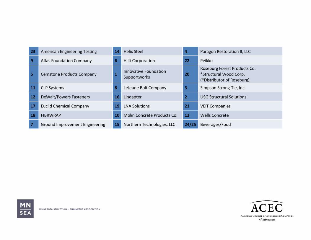
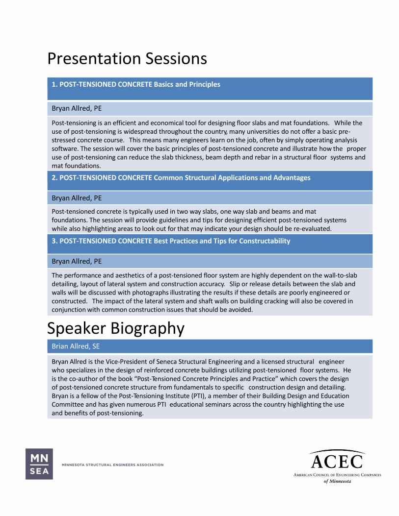
23 American Engineering Testing 14 Helix Steel 4 Paragon Restoration II, LLC
9 Atlas Foundation Company 6 Hilti Corporation 22 Peikko
5 Cemstone Products Company 1 Innovative Foundation Supportworks
20 Roseburg Forest Products Co. *Structural Wood Corp. (*Distributor of Roseburg)
11 CLP Systems 8 LeJeune Bolt Company 3 Simpson Strong-Tie, Inc.
12 DeWalt/Powers Fasteners 16 Lindapter 2 USG Structural Solutions
17 Euclid Chemical Company 19 LNA Solutions 21 VEIT Companies
18 FIBRWRAP 10 Molin Concrete Products Co. 13 Wells Concrete
7 Ground Improvement Engineering 15 Northern Technologies, LLC 24/25 Beverages/Food
1
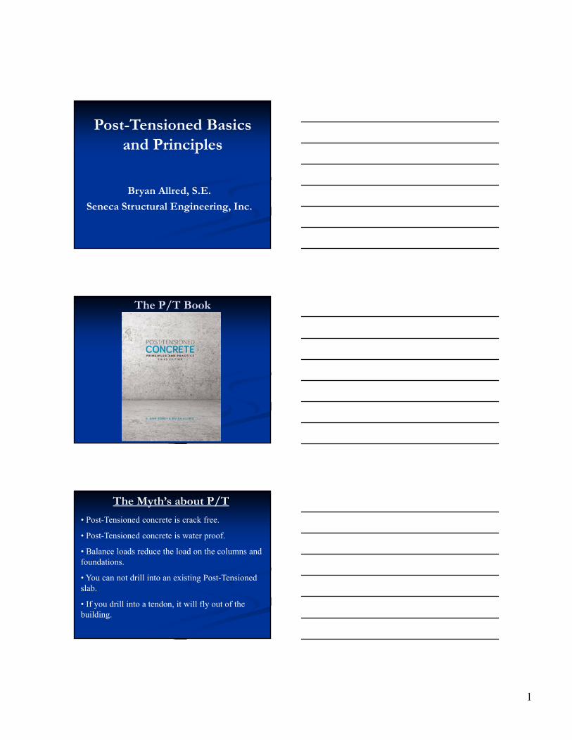
Post-Tensioned Basics and Principles
Bryan Allred, S.E.
Seneca Structural Engineering, Inc.
The P/T Book
The Myth’s about P/T
• Post-Tensioned concrete is crack free.
• Post-Tensioned concrete is water proof.
• Balance loads reduce the load on the columns and foundations.
• You can not drill into an existing Post-Tensioned slab.
• If you drill into a tendon, it will fly out of the building.
2
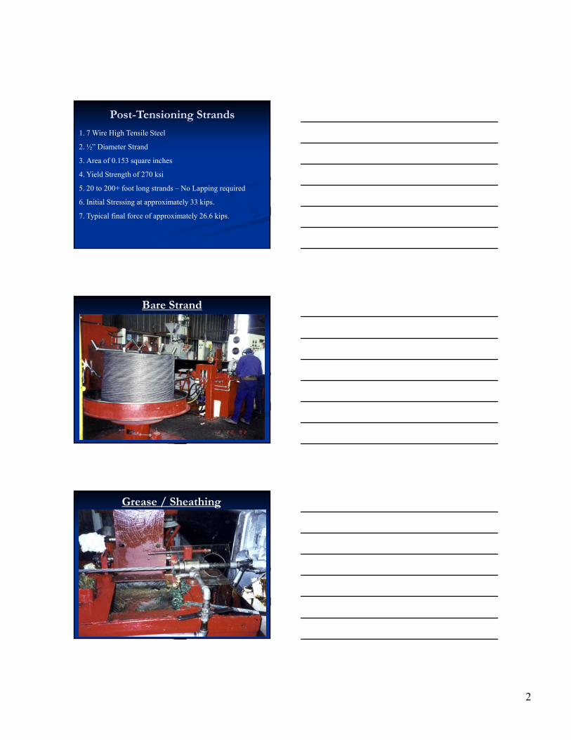
Post-Tensioning Strands
1. 7 Wire High Tensile Steel
2. ½” Diameter Strand
3. Area of 0.153 square inches
4. Yield Strength of 270 ksi
5. 20 to 200+ foot long strands – No Lapping required
6. Initial Stressing at approximately 33 kips.
7. Typical final force of approximately 26.6 kips.
Bare Strand
Grease / Sheathing
3
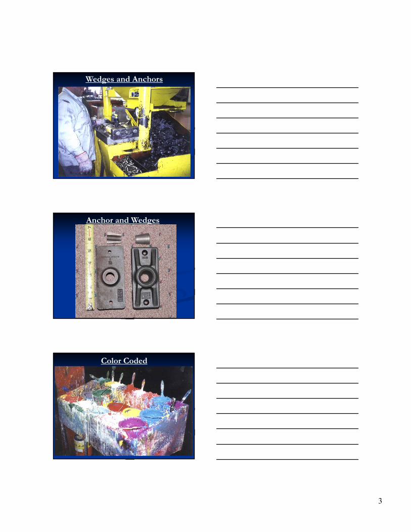
Wedges and Anchors
Anchor and Wedges
Color Coded
4
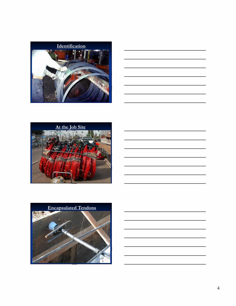
Identification
At the Job Site
Encapsulated Tendons
5
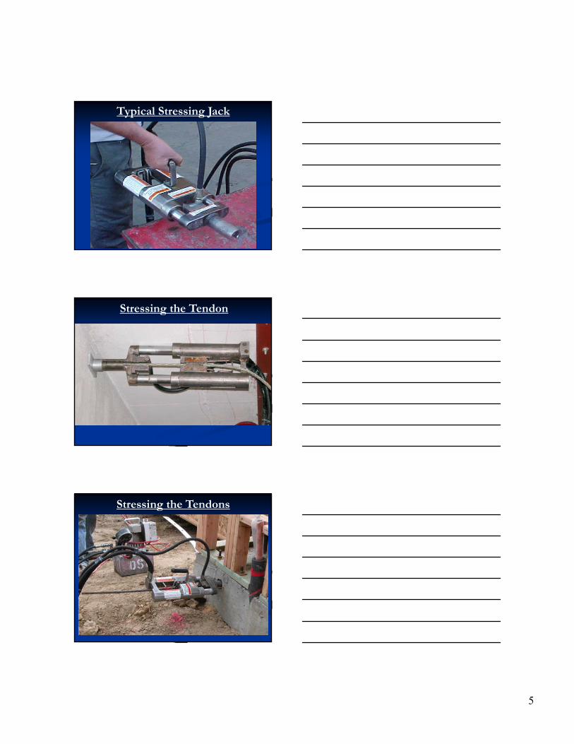
Typical Stressing Jack
Stressing the Tendon
Stressing the Tendons

6
Stressing the Tendons
General Tendon Layout
General Tendon Layout
7
©Copyright Post-Tensioning Institute. All rights reserved 19
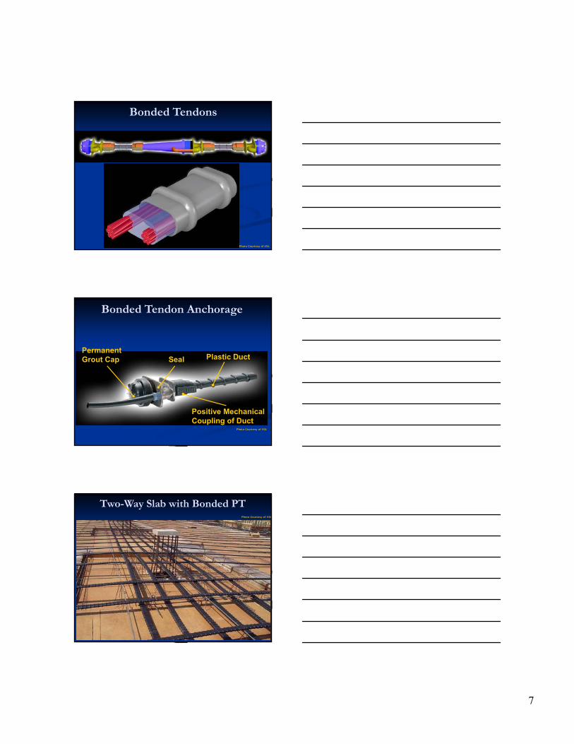
Bonded Tendons
Photo Courtesy of VSL
©Copyright Post-Tensioning Institute. All rights reserved 20
Bonded Tendon Anchorage
PermanentGrout Cap Seal
Positive MechanicalCoupling of Duct
Plastic Duct
Photo Courtesy of VSL
©Copyright Post-Tensioning Institute. All rights reserved 21
Two-Way Slab with Bonded PT Photo Courtesy of VSL
8
©Copyright Post-Tensioning Institute. All rights reserved 22
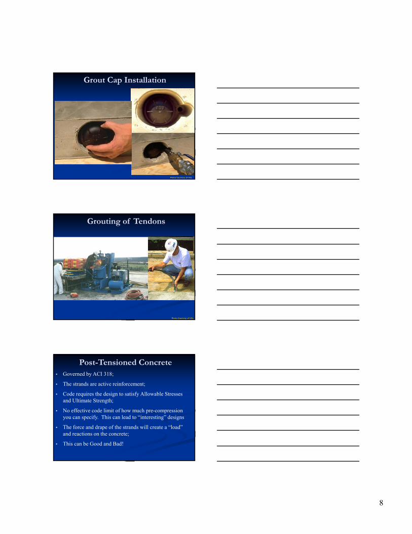
Grout Cap Installation
Photo Courtesy of VSL
©Copyright Post-Tensioning Institute. All rights reserved 23
Grouting of Tendons
Photo Courtesy of VSL
Post-Tensioned Concrete• Governed by ACI 318;
• The strands are active reinforcement;
• Code requires the design to satisfy Allowable Stresses and Ultimate Strength;
• No effective code limit of how much pre-compression you can specify. This can lead to “interesting” designs
• The force and drape of the strands will create a “load” and reactions on the concrete;
• This can be Good and Bad!
9
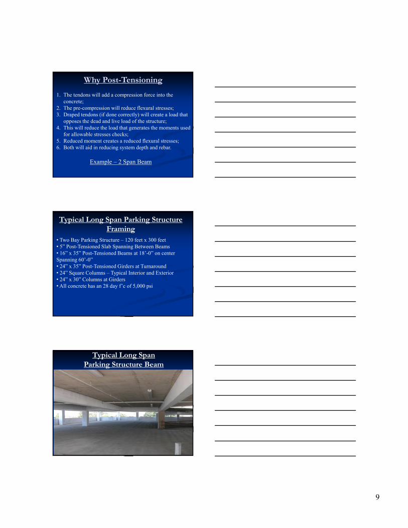
Why Post-Tensioning
1. The tendons will add a compression force into the concrete;
2. The pre-compression will reduce flexural stresses;3. Draped tendons (if done correctly) will create a load that
opposes the dead and live load of the structure;4. This will reduce the load that generates the moments used
for allowable stresses checks; 5. Reduced moment creates a reduced flexural stresses;6. Both will aid in reducing system depth and rebar.
Example – 2 Span Beam
Typical Long Span Parking Structure Framing
• Two Bay Parking Structure – 120 feet x 300 feet • 5” Post-Tensioned Slab Spanning Between Beams• 16” x 35” Post-Tensioned Beams at 18’-0” on center Spanning 60’-0”• 24” x 35” Post-Tensioned Girders at Turnaround• 24” Square Columns – Typical Interior and Exterior• 24” x 30” Columns at Girders•All concrete has an 28 day f’c of 5,000 psi
Typical Long Span Parking Structure Beam

10
Long Span Beam Detail
Loading
Dead Load:5” P/T Slab 63 PSFMech’l/Elec’l/Misc. 5 PSFP/T Beams @ 18 feet on center 28 PSF (96 PSF)P/T Girders 3 PSFSpandrels 5 PSFColumns 10 PSFShear Walls 25 PSF
Live Load:Passenger Vehicles Only 40 PSF(Unreducible for Slabs)/Beams/Girders)
Typical Two Span Beam
The beam elevation above is what is typically used in design offices to identify the number of strands and their location along the beam.
The tendon profile shown is what is typically seen in the field. The curvature of the tendons will reverse near the girders and the exterior columns. To simplify the math, a simple parabola will be assumed between the columns and the girder at grid B.

11
Simple Parabolic Profile
Dead and Live Load
WDL= 0.096 ksf * 18’ = 1.73 kips/foot
WLL= 0.040 ksf * 18’ = 0.72 kips/foot
WTL = 2.45 kips/foot
T-Section Properties – ACI 8.12.2
Beff : Width of slab effective for beam design/analysis
Lesser of: 1) L (beam span) /4 = 60’*12 / 4 = 180”
2) 16*t + bw = (16*5”)+16” = 96” (Controls)
3) One half the clear distance to the next web = (18’*12) – 16” = 200”
t = Slab thickness in inches
bw = Beam width – For simplicity we will use 16 inches for the full depth of the beam

12
T-Section Beam Section Properties
For simplicity, the beam is assumed to be a constant 16” wide
A = (96”*5”) + (30”*16”) = 960 in2
CGt = ((96”*5”*2.5”) + (30”*16”*20”)) / 960 in2
= 11.25” (from top)
I = b*h3/12 + A*d2 (Parallel Axis)= (96”*53/12) + (96”*5”*(11.25”-2.5”)2 )+ (16”*303/12) +
(30”*16”*(20”-11.25”)2) = 110,500 in4
ST = 110,500/11.25” = 9,822.2 in3
SB = 110,500/23.75” = 4,652.6 in3
Simplified Beam Model
For simplicity of analysis, the exterior columns and interior girder will be assumed to pin/roller support.
Step 1 – Determine balanced loads from the post-tensioning force and its drape.
Balanced Load
Since the tendon is draped (not flat) between the supports, once stressing begins, it will want to “straighten out” to have no curvature between grids A to B and B to C. As it “straightens” it will push upward on the beam.
For a given force, the larger the ‘a’ dimension, the more upward force is generated as it tries to straighten.
13
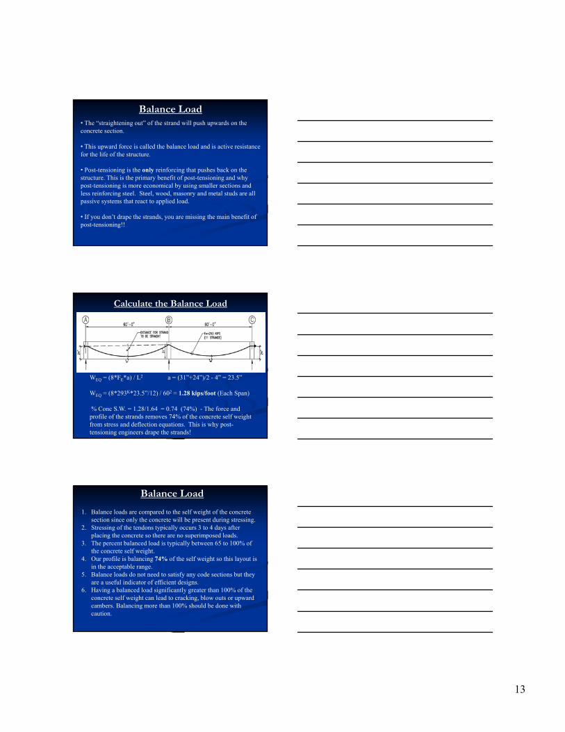
Balance Load• The “straightening out” of the strand will push upwards on the concrete section.
• This upward force is called the balance load and is active resistance for the life of the structure.
• Post-tensioning is the only reinforcing that pushes back on the structure. This is the primary benefit of post-tensioning and why post-tensioning is more economical by using smaller sections and less reinforcing steel. Steel, wood, masonry and metal studs are all passive systems that react to applied load.
• If you don’t drape the strands, you are missing the main benefit of post-tensioning!!
Calculate the Balance Load
WEQ = (8*FE*a) / L2 a = (31”+24”)/2 - 4” = 23.5”
WEQ = (8*293K*23.5”/12) / 602 = 1.28 kips/foot (Each Span)
% Conc S.W. = 1.28/1.64 = 0.74 (74%) - The force and profile of the strands removes 74% of the concrete self weight from stress and deflection equations. This is why post-tensioning engineers drape the strands!
Balance Load
1. Balance loads are compared to the self weight of the concrete section since only the concrete will be present during stressing.
2. Stressing of the tendons typically occurs 3 to 4 days after placing the concrete so there are no superimposed loads.
3. The percent balanced load is typically between 65 to 100% of the concrete self weight.
4. Our profile is balancing 74% of the self weight so this layout is in the acceptable range.
5. Balance loads do not need to satisfy any code sections but they are a useful indicator of efficient designs.
6. Having a balanced load significantly greater than 100% of the concrete self weight can lead to cracking, blow outs or upward cambers. Balancing more than 100% should be done with caution.

14
Beam Model w/ Equivalent Loads
The beam model shows all loads on the beam. The tendons have been replaced with the load they impart on the beam which is the axial force of the strands and the balance load.
Note: If the balance loads are not opposite of the dead and live load, your drape is wrong and you are not resisting load!
Beam Model w/ Net Loads
• The net load is generated by subtracting the balance load from the dead and live load.
• The direct force from the anchors is applied at the center of gravity of the section to eliminate any end moments.
Beam Model w/ Net Loads
• The net loading will be used to determine the flexural stresses at the critical locations along the span of the beam.
• The net loading is NOT used in ultimate strength design. Balance loads are only used to satisfy the allowable stress requirements of the building code.
• The net loading is NOT used in determining column or footing loads. Post-Tensioning does not reduce the total weight of the structure.
15
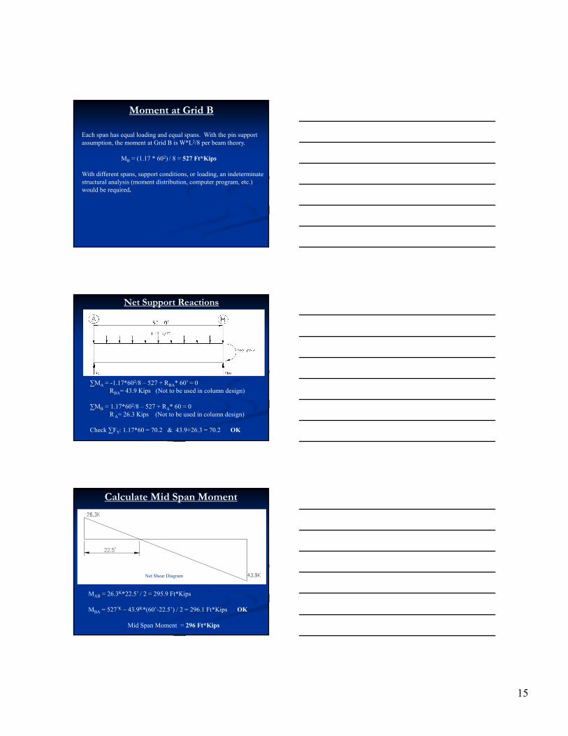
Moment at Grid B
Each span has equal loading and equal spans. With the pin support assumption, the moment at Grid B is W*L2/8 per beam theory.
MB = (1.17 * 602) / 8 = 527 Ft*Kips
With different spans, support conditions, or loading, an indeterminate structural analysis (moment distribution, computer program, etc.) would be required.
Net Support Reactions
∑MA = -1.17*602/8 – 527 + RBA* 60’ = 0 RBA= 43.9 Kips (Not to be used in column design)
∑MB = 1.17*602/8 – 527 + RA* 60 = 0 R A= 26.3 Kips (Not to be used in column design)
Check ∑FY: 1.17*60 = 70.2 & 43.9+26.3 = 70.2 OK
Calculate Mid Span Moment
MAB = 26.3K*22.5’ / 2 = 295.9 Ft*Kips
MBA = 527’K – 43.9K*(60’-22.5’) / 2 = 296.1 Ft*Kips OK
Mid Span Moment = 296 Ft*Kips
Net Shear Diagram

16
Net Service Moment Diagram
•Always draw moment diagrams to the tensile face of the concrete section. The tensile face indicates what portion of the beam requires reinforcing for strength.
• Note the diagram matches the general drape of the tendons. The tendons change their vertical location in the beam to follow the tensile moment diagram. Strands are at the top of the beam over the support and near the bottom at mid span.
Flexural Stresses
Grid B: σB = P/A +/- M/S
σB top = (293 / 960) – (527*12) / 9822.2 = -0.339 ksi (Tension)
σB bot = (293 / 960) + (527*12) / 4652.6 = 1.66 ksi (Comp)
Mid Span: σAB = P/A +/- M/S
σAB bot = (293 / 960) – (296*12) / 4652.6 = -0.459 ksi (Tension)
σAB top = (293 / 960) + (296*12) / 9822.2 = 0.667 ksi (Comp)
What if we didn’t drape the tendons??
• Without draping the strands, there would be no balance load to offset the dead and live load.
• Only the axial compression would be available to reduce the tensile stresses.
• Placing the strands at the center of gravity of the section would require additional rebar at the locations of high flexural demands.

17
What if we didn’t drape the tendons??
With no balance load, the total load is the total dead and live load which is 2.45 kips per foot. With the pin support assumption, the moment at Grid B is W*L2/8 per beam theory.
MB = (2.45 * 602) / 8 = 1,102.50 Ft*Kips
• Note this would be the same moment if you were designing wood, steel, rebar only concrete, etc.
What if we didn’t drape the tendons??
• Grid B: σB = P/A +/- M/S
• σB top = (293 / 960) – (1,103*12) / 9822.2 = -1.042 ksi (Tension)
• σB bot = (293 / 960) + (1,103*12) / 4652.6 = 3.15 ksi (Comp)
• For no increase in cost, draping the strands reduced the flexural stresses from 1.042 ksi to 0.339 ksi which is a reduction of (1.042/.339) 3.07 times.
This is why we drape the tendons!!!
50
What if we didn’t use P/T
MB = (2.45 * 602) / 8 = 1,102.50 Ft*Kips
• Note this would be the same moment if you were designing wood, steel, rebar only concrete, etc.
•Grid B: σB = M/S
•σB top = (1,103*12) / 9822.2 = 1.348 ksi (Tension)
• 1.348/0.339 = 3.98
Basically a factor of 4 Increase!

18
Questions
1
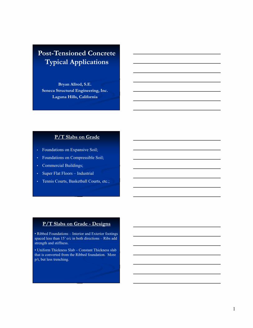
Post-Tensioned Concrete Typical Applications
Bryan Allred, S.E.
Seneca Structural Engineering, Inc.
Laguna Hills, California
P/T Slabs on Grade
• Foundations on Expansive Soil;
• Foundations on Compressible Soil;
• Commercial Buildings;
• Super Flat Floors – Industrial
• Tennis Courts, Basketball Courts, etc.;
P/T Slabs on Grade - Designs
• Ribbed Foundations – Interior and Exterior footings spaced less than 15’ o/c in both directions – Ribs add strength and stiffness.
• Uniform Thickness Slab – Constant Thickness slab that is converted from the Ribbed foundation. More p/t, but less trenching.

2
Creating the Ribs
Sand and Vapor Retarder
Ribbed Slab on Grade
3
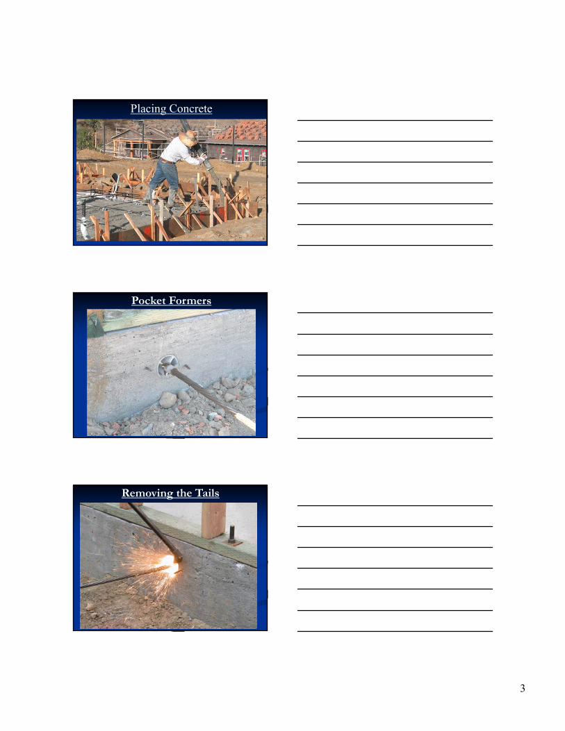
Placing Concrete
Pocket Formers
Removing the Tails
4
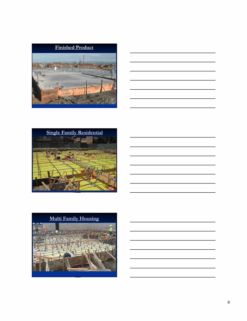
Finished Product
Single Family Residential
Multi Family Housing
5
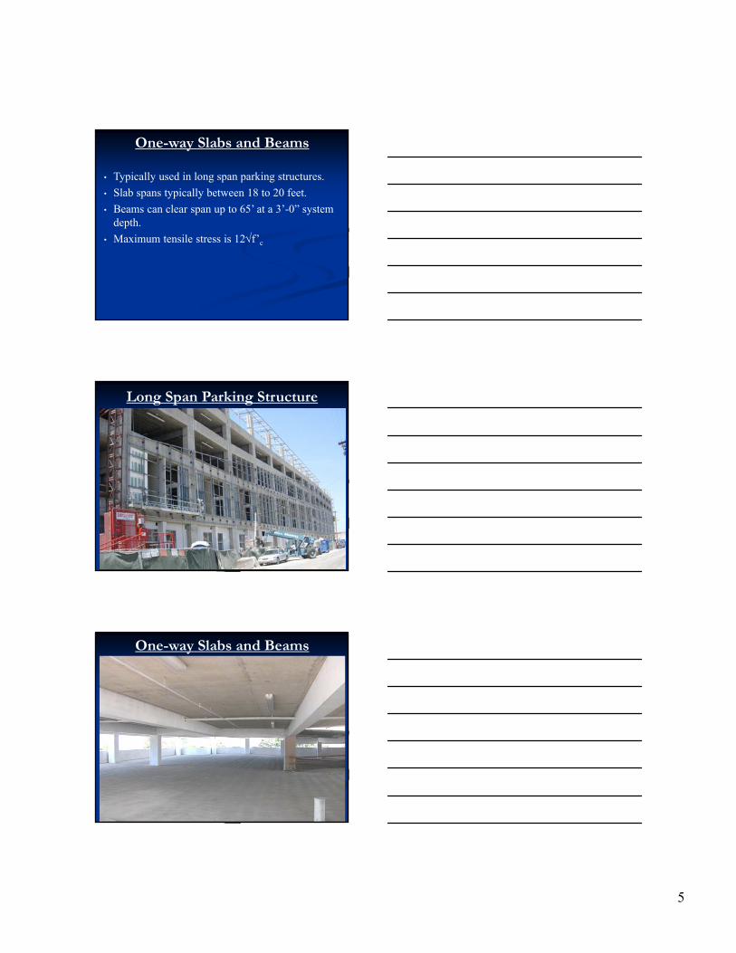
One-way Slabs and Beams
• Typically used in long span parking structures.
• Slab spans typically between 18 to 20 feet.
• Beams can clear span up to 65’ at a 3’-0” system depth.
• Maximum tensile stress is 12f’c
Long Span Parking Structure
One-way Slabs and Beams

6
One-way Slabs and Beams
Long Span Parking Structures
Long Span Parking Structures
7
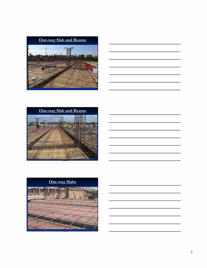
One-way Slab and Beams
One-way Slab and Beams
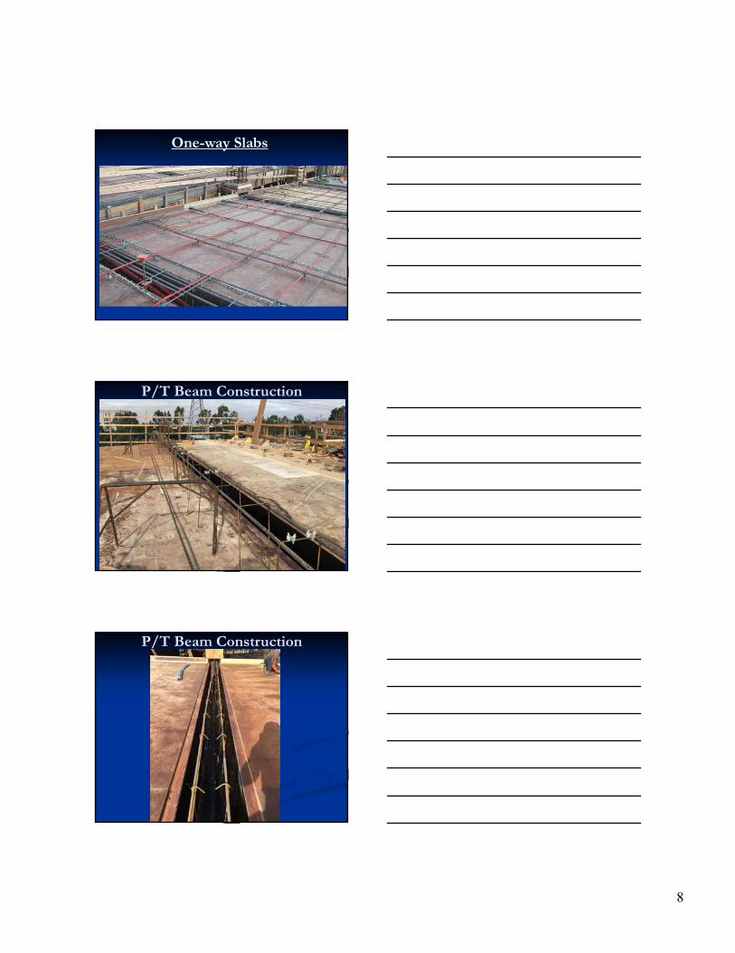
One-way Slabs
8
One-way Slabs
P/T Beam Construction
P/T Beam Construction

9
P/T Beam Construction
P/T Beam Construction
P/T Beam Construction
10
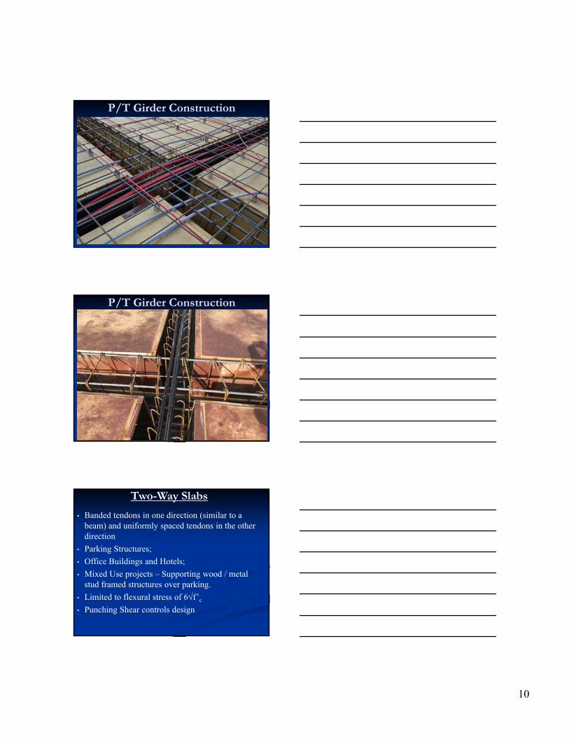
P/T Girder Construction
P/T Girder Construction
Two-Way Slabs
• Banded tendons in one direction (similar to a beam) and uniformly spaced tendons in the other direction
• Parking Structures;
• Office Buildings and Hotels;
• Mixed Use projects – Supporting wood / metal stud framed structures over parking.
• Limited to flexural stress of 6f’c
• Punching Shear controls design

11
Two-way Slabs
Two Way Slab Building
Two Way Slab Building

12
Two Way Slab Plan
Band & Uniform Direction
Band & Uniform Direction
13
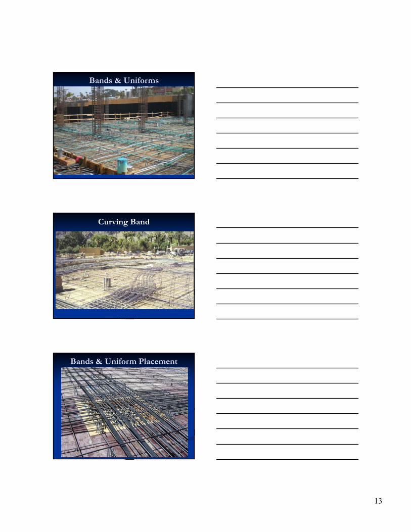
Bands & Uniforms
Curving Band
Bands & Uniform Placement

14
Tendon Placement
Tendon Placement
Shear Studs
15
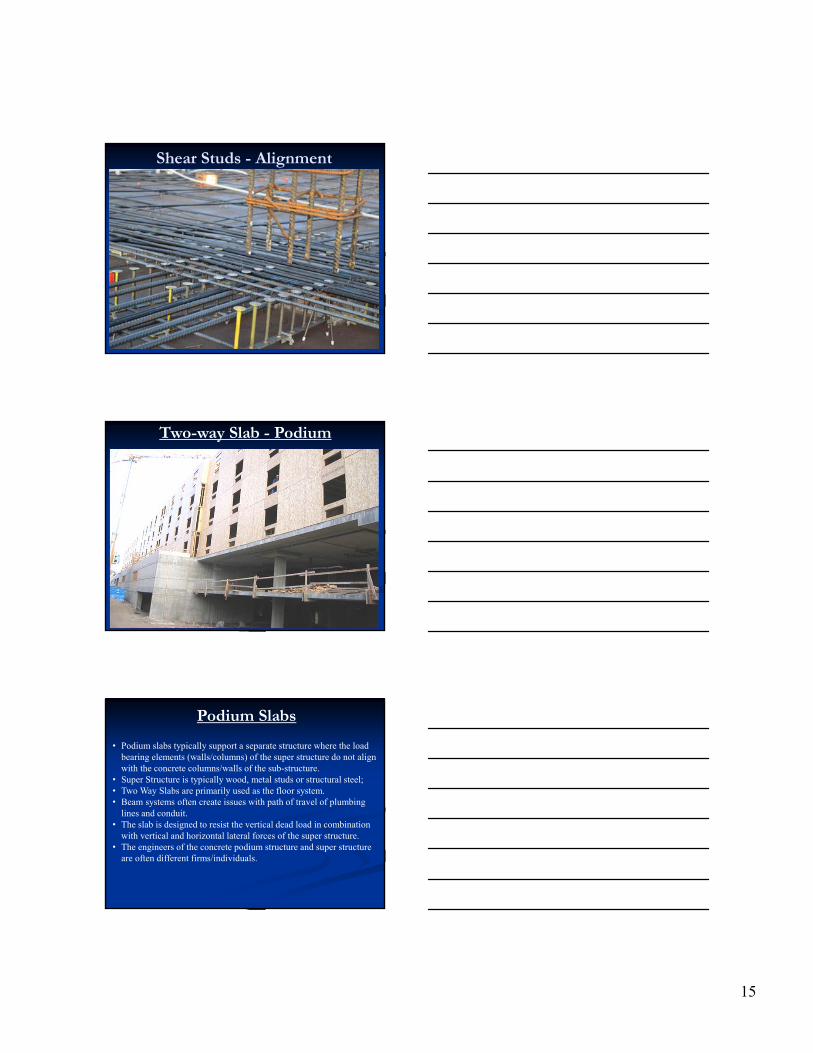
Shear Studs - Alignment
Two-way Slab - Podium
Podium Slabs
• Podium slabs typically support a separate structure where the load bearing elements (walls/columns) of the super structure do not align with the concrete columns/walls of the sub-structure.
• Super Structure is typically wood, metal studs or structural steel;• Two Way Slabs are primarily used as the floor system.• Beam systems often create issues with path of travel of plumbing
lines and conduit. • The slab is designed to resist the vertical dead load in combination
with vertical and horizontal lateral forces of the super structure. • The engineers of the concrete podium structure and super structure
are often different firms/individuals.
16
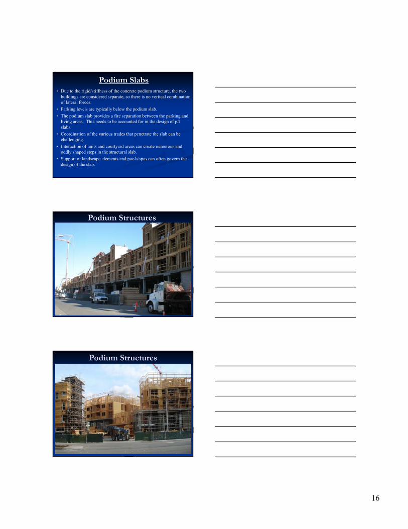
Podium Slabs• Due to the rigid/stiffness of the concrete podium structure, the two
buildings are considered separate, so there is no vertical combination of lateral forces.
• Parking levels are typically below the podium slab.
• The podium slab provides a fire separation between the parking and living areas. This needs to be accounted for in the design of p/t slabs.
• Coordination of the various trades that penetrate the slab can be challenging.
• Interaction of units and courtyard areas can create numerous and oddly shaped steps in the structural slab.
• Support of landscape elements and pools/spas can often govern the design of the slab.
Podium Structures
Podium Structures

17
Typical Podium Cross Section
Podium Slabs
Podium Slabs
18
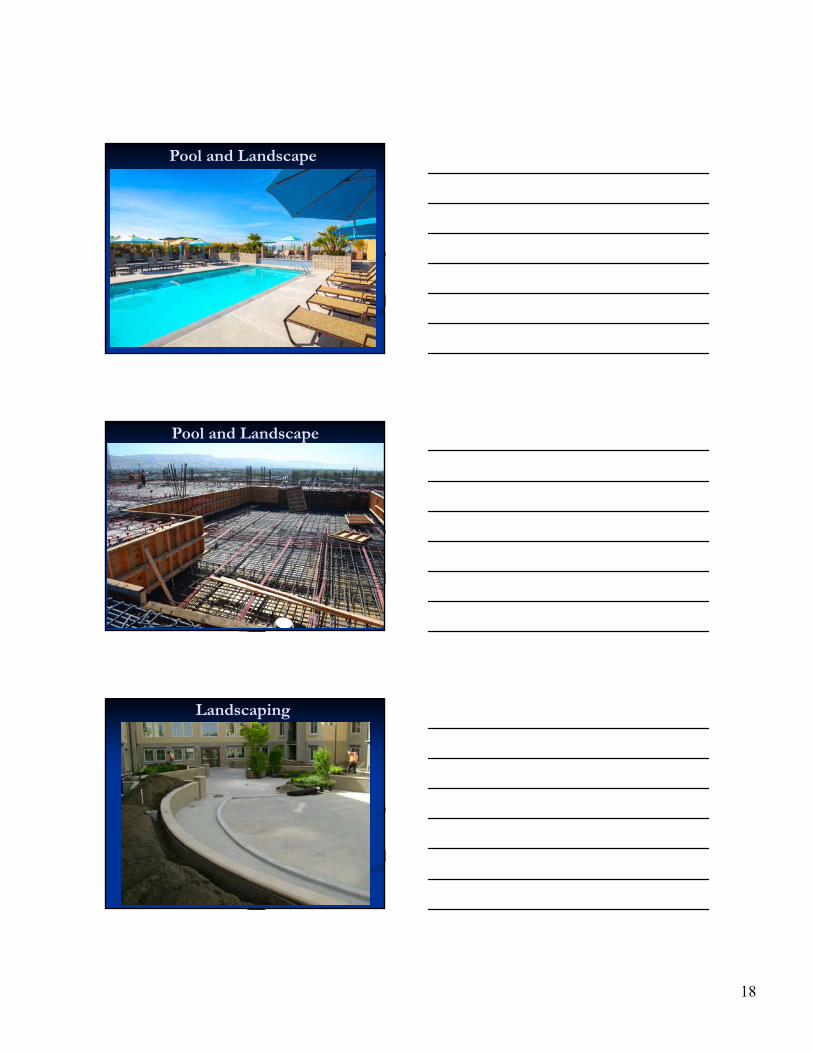
Pool and Landscape
Pool and Landscape
Landscaping

19
Steel Frames on the Podium
Reasons to Consider P/T Decks
• A post-tensioned deck is typically at least 2” thinner than a well designed rebar only deck.
• Reduction in seismic mass, column and foundation loads.
• Substantially reduction in rebar
• All leading to Financial Savings
Reasons to Consider P/T Decks
• Long-term Creep Problems Virtually Eliminated by Load Balancing (125% +/- of Concrete Weight)
• Deck Moment of Inertia Approaches I (gross) As Opposed to I (effective)
• Both lead to smaller deflections – This is critical to podium or other slabs that support fragile facades
20
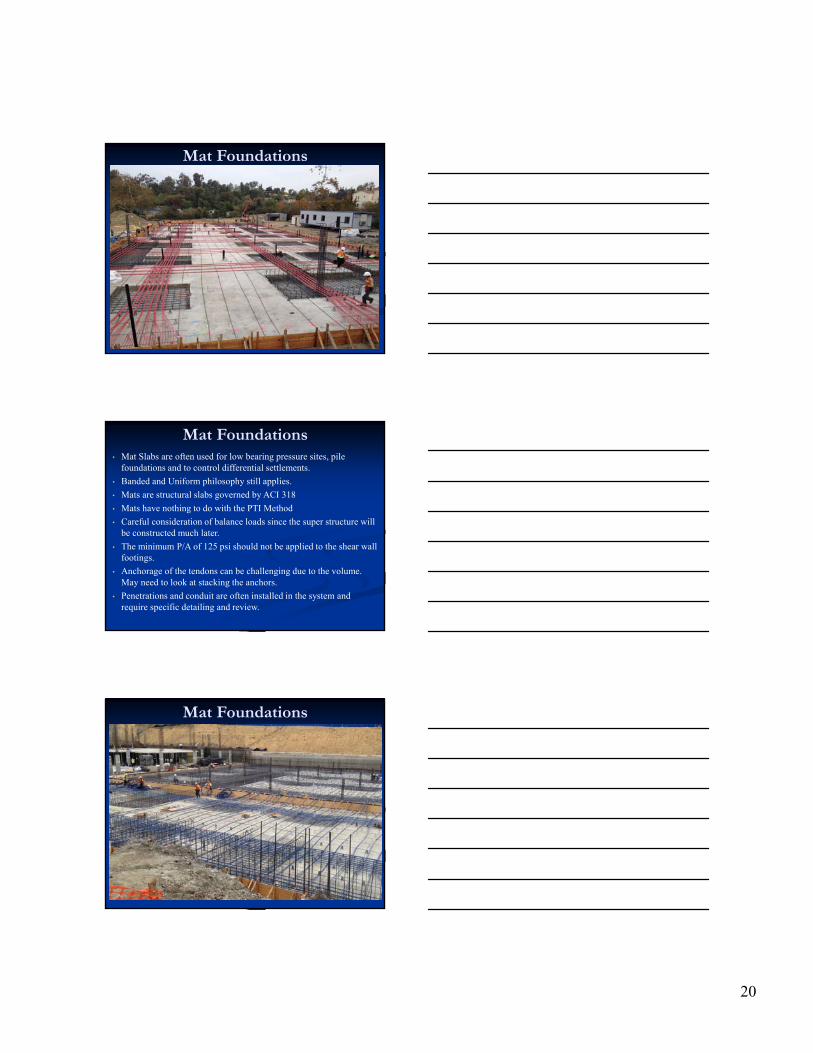
Mat Foundations
Mat Foundations• Mat Slabs are often used for low bearing pressure sites, pile
foundations and to control differential settlements.
• Banded and Uniform philosophy still applies.
• Mats are structural slabs governed by ACI 318
• Mats have nothing to do with the PTI Method
• Careful consideration of balance loads since the super structure will be constructed much later.
• The minimum P/A of 125 psi should not be applied to the shear wall footings.
• Anchorage of the tendons can be challenging due to the volume. May need to look at stacking the anchors.
• Penetrations and conduit are often installed in the system and require specific detailing and review.
Mat Foundations

21
Mat Foundations
Mat Foundations
Mat Foundations
22
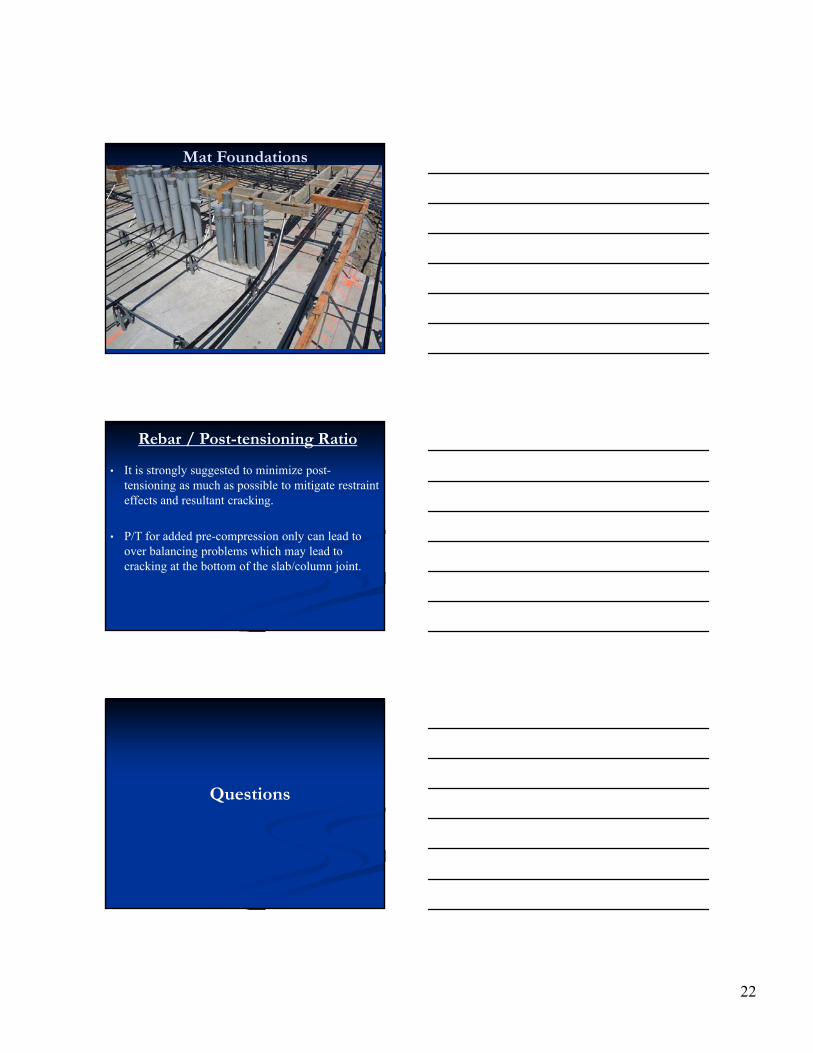
Mat Foundations
Rebar / Post-tensioning Ratio
• It is strongly suggested to minimize post-tensioning as much as possible to mitigate restraint effects and resultant cracking.
• P/T for added pre-compression only can lead to over balancing problems which may lead to cracking at the bottom of the slab/column joint.
Questions
1
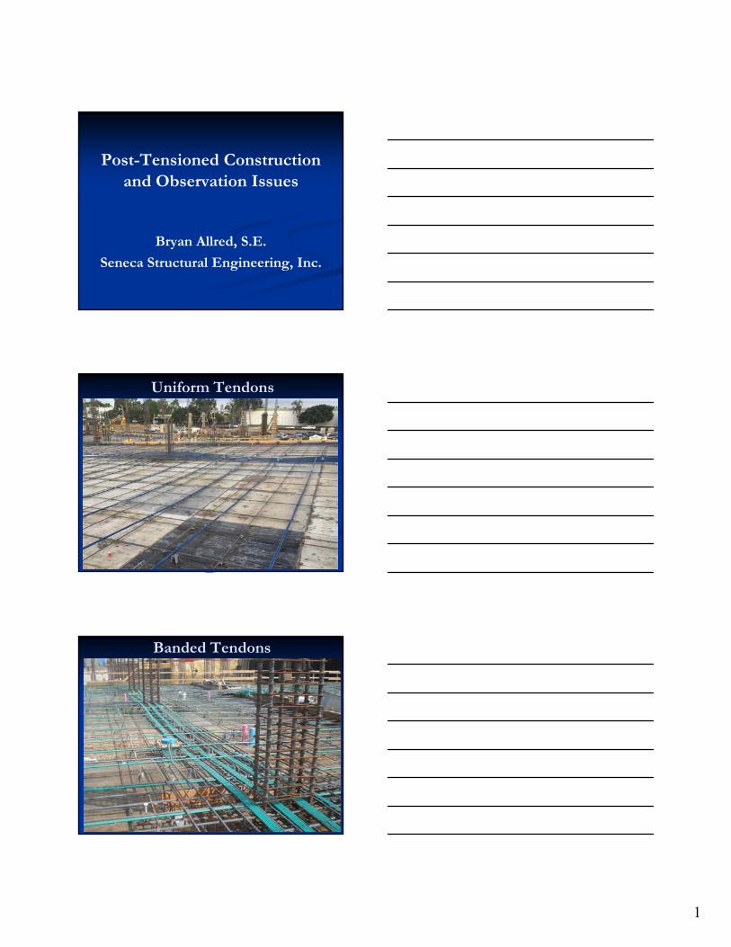
Post-Tensioned Construction and Observation Issues
Bryan Allred, S.E.
Seneca Structural Engineering, Inc.
Uniform Tendons
Banded Tendons

2
Bands & Uniforms
One Way Slabs
Balance Loads
1. Balance loads are compared only to the self weight of the concrete section since only the concrete will be present during stressing.
2. Stressing of the tendons typically occurs 3 to 4 days after placing the concrete so there are no superimposed loads.
3. The percent balanced load is typically between 65 to 100% of the concrete self weight for most structures.
4. Balance loads do not need to satisfy any code sections but they are a useful indicator of efficient designs.
5. Having a balanced load significantly greater than 100% of the concrete self weight can lead to cracking, blow outs or upward cambers. Balancing more than 100% should be done with caution.

3
Over Balancing
Over Balancing
Over Balancing

4
Structural Drawings
Structural Drawings
Structural Drawings
6.75
1.25
6.75
34
6.75
1.25
6.75
34
26.75
1.25
6.75
34
44
1.25
6.75
34
44
1.25
6.75
34
41.25
6.25
44
4 44
1.25
6.75
44
44
6.75
4
1.25
6.25
6.75
1.25
6.75
44
6.75
1.25
6.75
44
6.75
1.25
6.75
44
1.25
6.75
6.75
44
6.25
6.25
44
1.25
6.75
1.25
6.75
44
1. 25
6. 75
6.75
44
6.75
1.25
6.75
44
6.75
1.25
6.25
44
6.25
1.25
6.75
44
6.75
1.25
6.75
44
6.75
1.25
6.75
44
6.75
1.75
6.75
44
6.75
1.75
6.75
44
25
6.75
1.75
6.75
44
1.8S
1.8S
1.8S
1.8S
1.8S
1.8S
1.8S
1.8S
1.8S
1.8S
1.8S
1.8S
1.8S
1.8S
1.8S
1.8S
1.8S
1.8S
1.8S
1.8S
1.8S
1.8S
1.8S
1.8S
1.8S
1.8S
1.8S
1.8S
1.8S
1.8S
1.8S
1.8S
1.8S
1.8S
1.8S
1.8S
1.8S
1.8S
1.8S
1.8S
1.8S
1.8S
1.8S
1.8S
1.8S
1.8S
.8S
1.8S
1.8S
1.8S
1.8S
1.8S
1.8S
1.8S
1.8S
1.8S
1.8S
1.8S
1. 8S
1.8S
1.8S
1.8S
1.8S
1.8S
1.8S
1.8S
1.8S
1.8S
1.8S
1.8S
1.8S
1.8S
1.8S
1.8S
1.8S
1.8S
1.8S
1.8S
1.8S
1.8S
1.8S
1.8S
1.8S
1.8S
1.8S
1.8S
1.8S
1.8S
1.8S
1.8S
1.8S
1.8S
1.8S
1.8S
1.8S
1.8S
1.8S
1.8S
1.8S
1.8S
1.8S
1.8S
1.8S
5
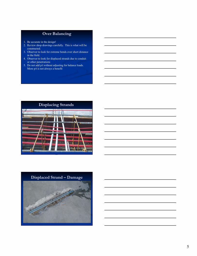
Over Balancing
1. Be accurate in the design!2. Review shop drawings carefully. This is what will be
constructed. 3. Observer to look for extreme bends over short distance
in the field. 4. Observer to look for displaced strands due to conduit
or other penetrations5. Do not add p/t without adjusting for balance loads.
More p/t is not always a benefit
Displacing Strands
Displaced Strand – Damage

6
Reverse Curvature
Displaced Strand – Damage
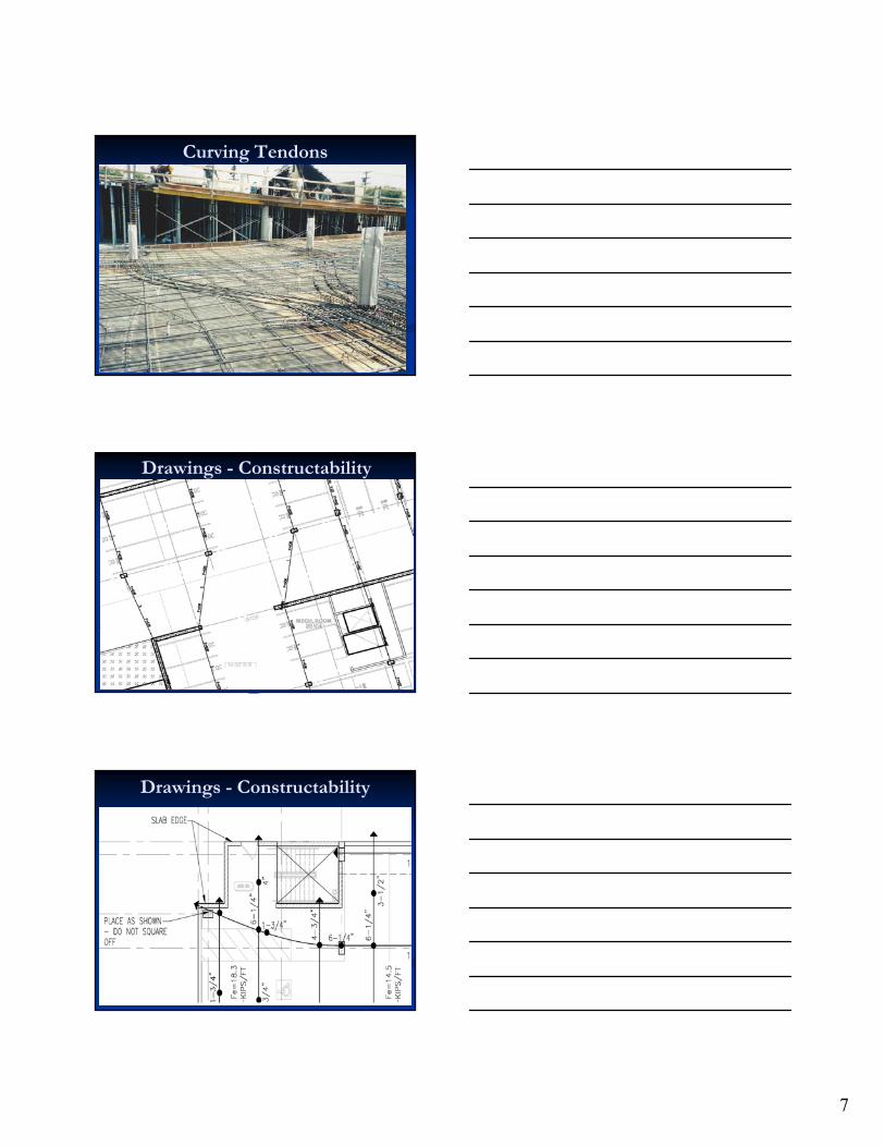
Curving Tendons
7
Curving Tendons
Drawings - Constructability
Drawings - Constructability

8
Shop Drawing Review
Curving Tendons
Curving Tendons
9
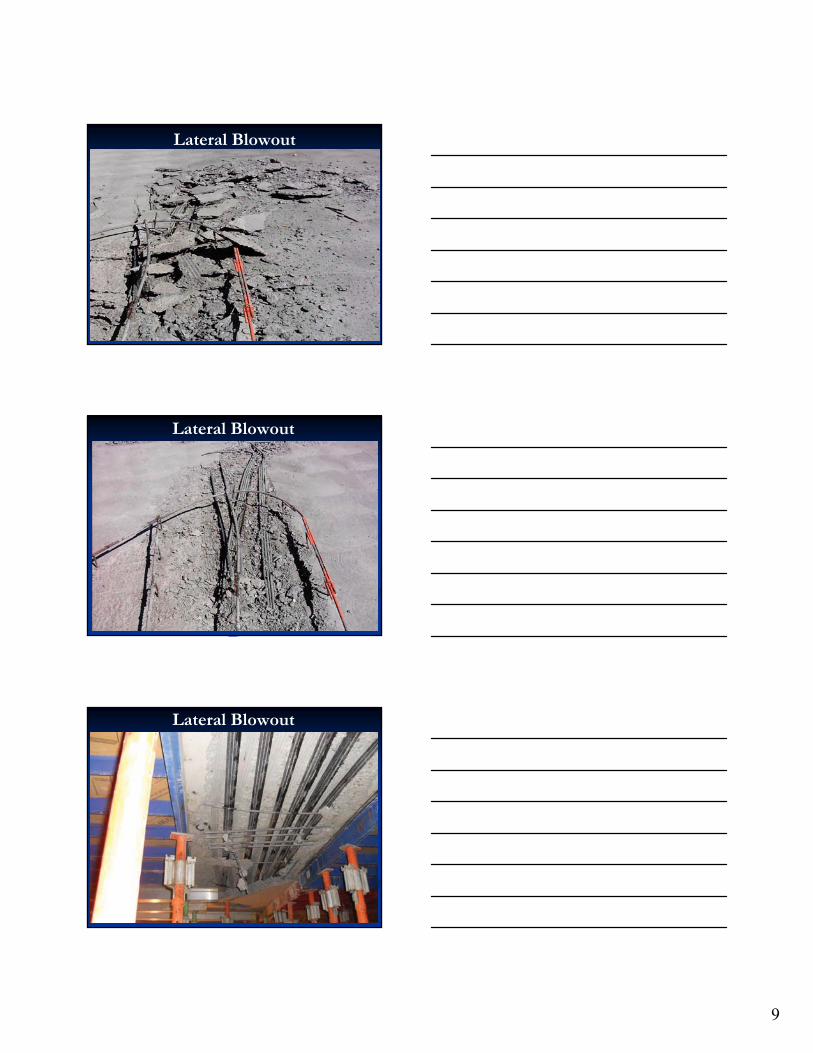
Lateral Blowout
Lateral Blowout
Lateral Blowout

10
Lateral Blowout
Curving Tendons
1. Use Common Sense!2. If a curve is required, curve the strands in the middle
portion of the slab. 3. Avoid curving tendons at the top or bottom of slab since
rebar cannot be installed due to cover. 4. Review shop drawings carefully. This is what will be
constructed. 5. Observer to look for extreme curves in the field. 6. Observer to look for localized curves to avoid conduit or
other penetrations.
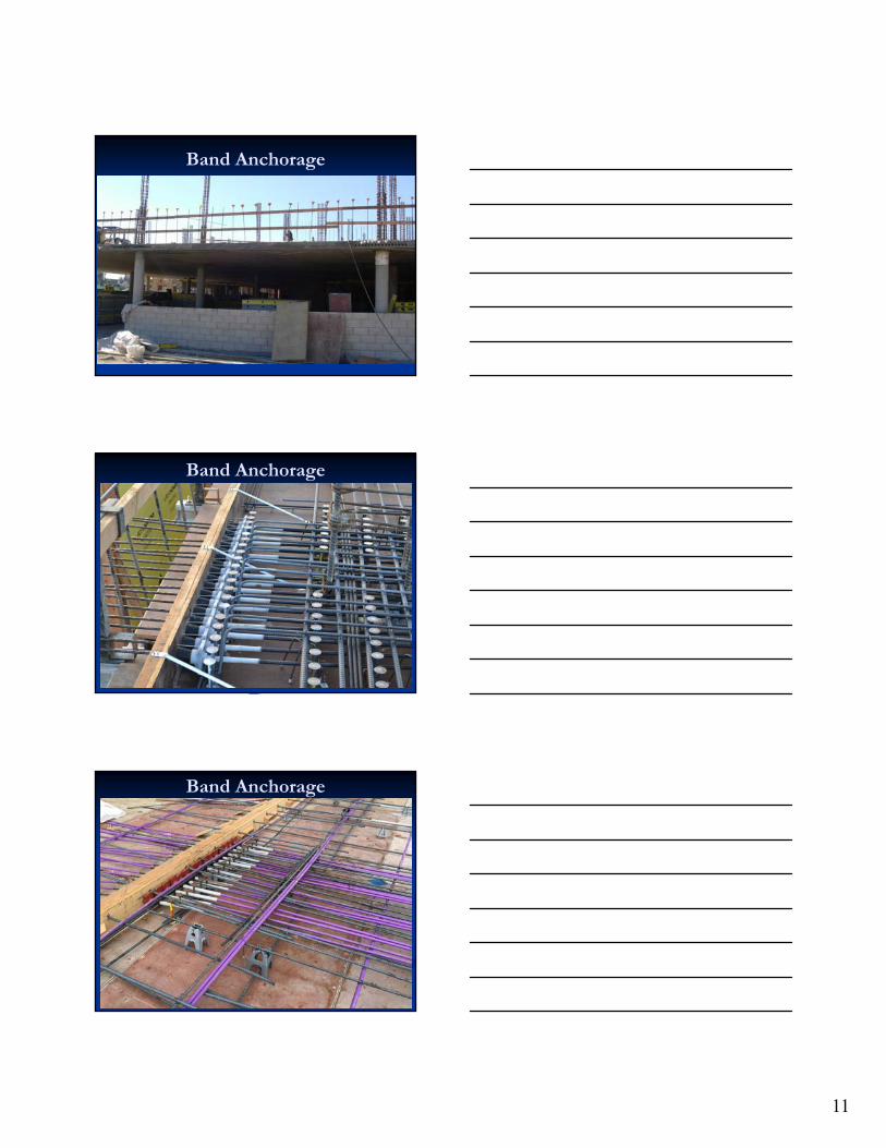
Band Anchorage
• In Two Way Slabs the P/A is based upon the full tributary width
• The banded tendons are anchored in an area much smaller than their tributary width
• A large force is applied to a relatively small area. A 30 foot wide section may be anchored in 5 feet – P/A goes up 6x!
• Very Large compression forces in this concrete. • Important to get solid, well consolidated concrete behind
the anchors.
11
Band Anchorage
Band Anchorage
Band Anchorage

12
Uniform Tendon Anchors
Band Anchorage
Penetrations at Anchorage

13
Overlapping Anchors
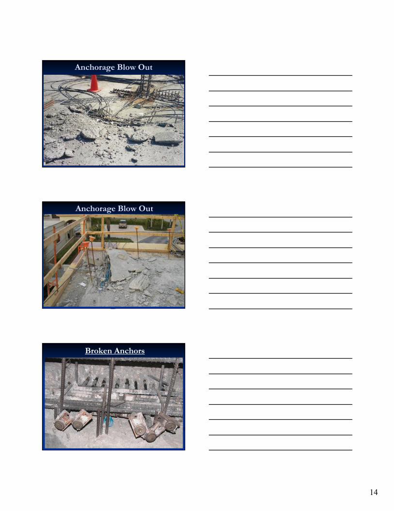
Anchorage Blow Outs
Anchorage Blow Outs
14
Anchorage Blow Out
Anchorage Blow Out
Broken Anchors

15
Consolidation at Anchors
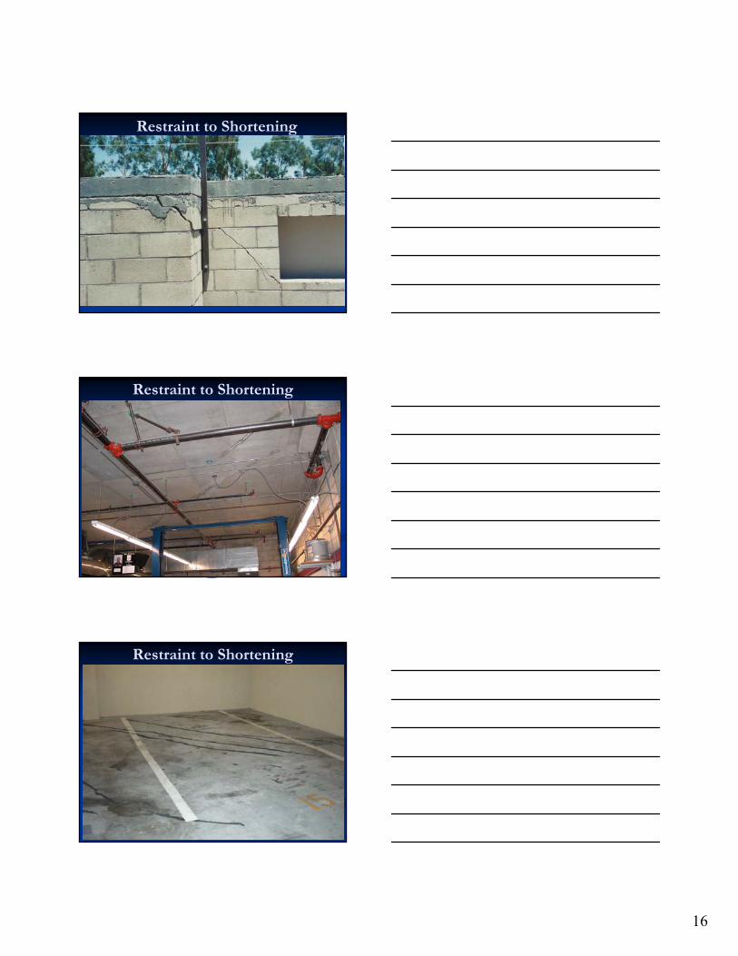
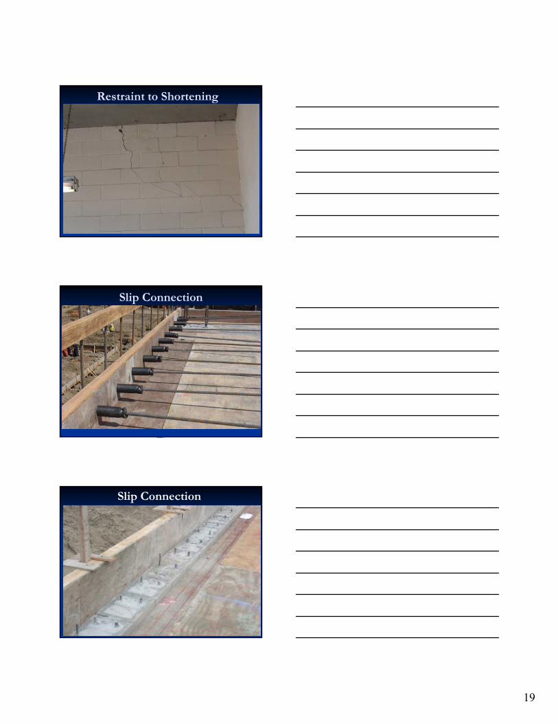
Restraint to Shortening
Restraint to Shortening
16
Restraint to Shortening
Restraint to Shortening
Restraint to Shortening

17
Restraint to Shortening
Restraint to Shortening
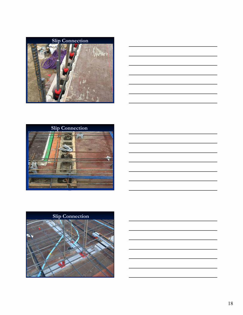
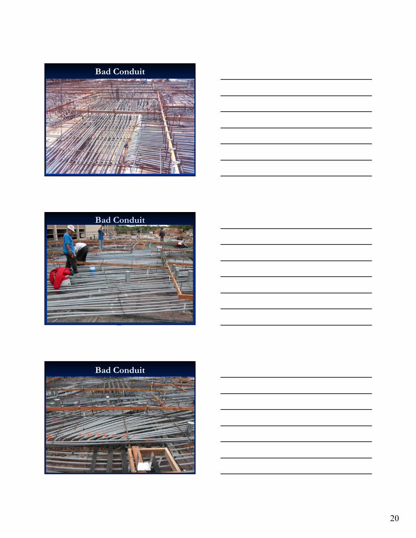
Slip Connection
18
Slip Connection
Slip Connection
Slip Connection
19
Restraint to Shortening
Slip Connection
Slip Connection
20
Bad Conduit
Bad Conduit
Bad Conduit

21
Bad Conduit
Conduit Plans
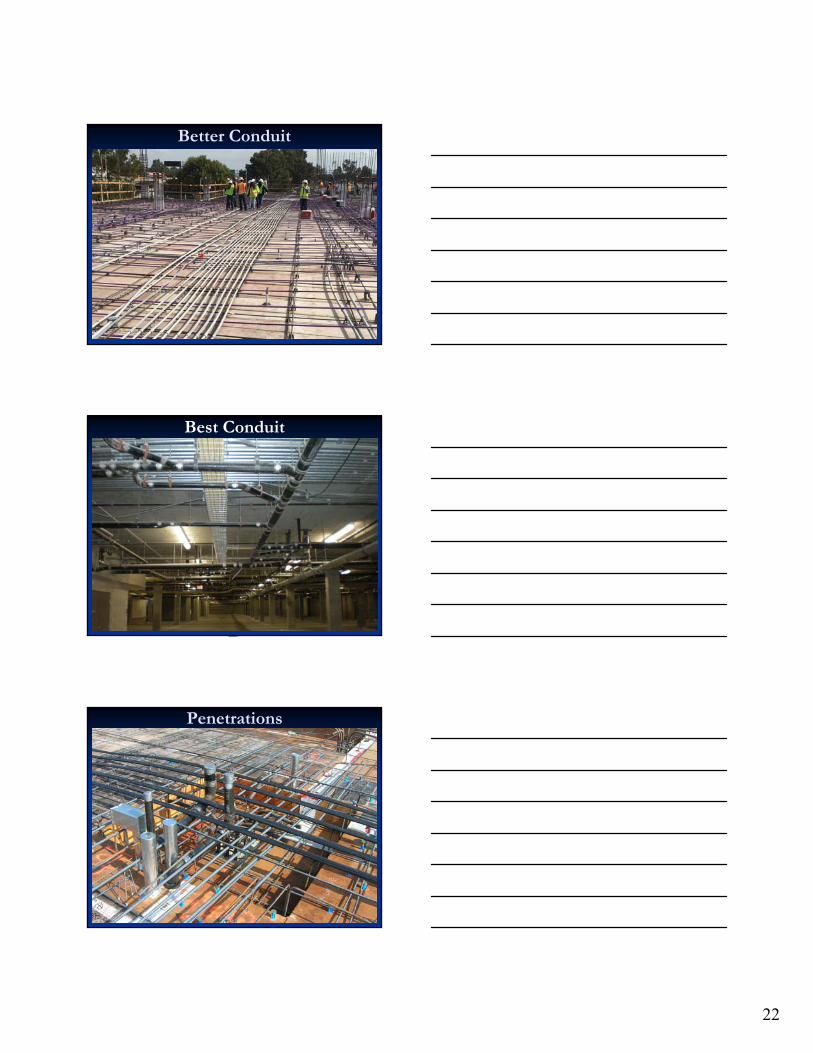
Better Conduit
22
Better Conduit
Best Conduit
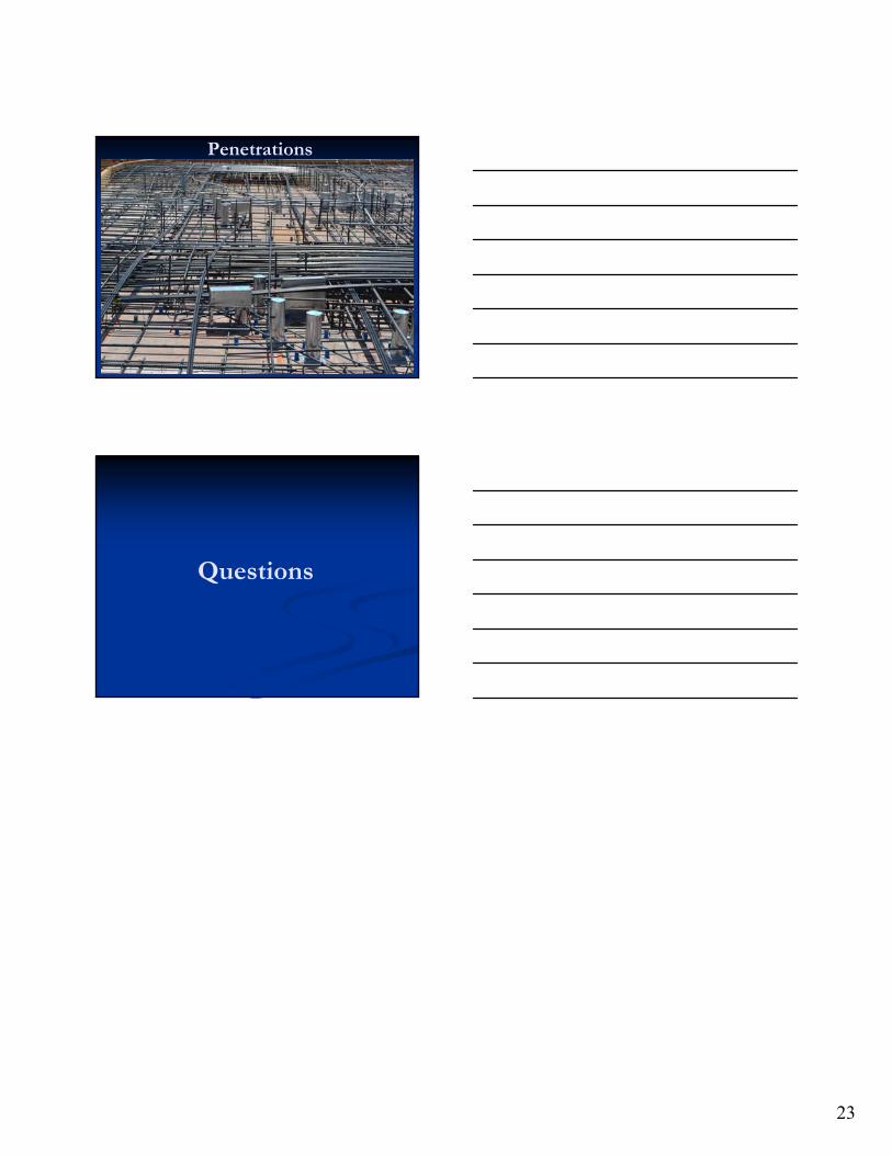
Penetrations
23
Penetrations
Questions


10201 Wayzata Blvd., Suite 240 Minnetonka, MN 55305
P: 952-593-5533 F: 952-593-5552 www.acecmn.org
Certificate of Attendance
For The Following ACEC/MN Educational Program:
Post - Tensioned Concrete Structures
(MNSEA Annual Seminar & Trade Show)
Presenter(s):
Bryan Allred, SE
Presented: 5/9/17 3.0 Professional Development Hours (PDH) Location: Marriott Minneapolis West, Minnetonka 0.3 Continuing Education Units (CEU) [ ] - I attended the entire 3 hour seminar. [ ] - I attended _________ hours of this seminar.
To the best of our knowledge, this educational program meets the requirements of the Board of AELSLAGID for continuing education. ACEC/MN makes no warranty, directly or indirectly, that this
program meets the standard established by the Board of AELSLAGID for continuing education.
Note: This certificate was distributed at the end of the educational program and only to those who were in attendance for the entire program. If there are any questions regarding this certificate, or if confirmation is
needed to verify the authenticity of this document, please contact the ACEC/MN office.
MINNESOTA STRUCTURAL ENGINEERS ASSOCIATION