Embed Size (px)
Citation preview

Journal ofElectron Spectroscopy and Related Phenomenu, 24 (1981) 189-204 Elsevler Sclentlflc Pubhshmg Company, Amsterdam - Prmted m The Netherlands
ANGLE-RESOLVING PHOTOELECTRON ENERGY ANALYZER DESIGNED FOR SYNCHROTRON RADIATION SPECTROSCOPY
G K OVREBO* and J L ERSKINE
Department ofPhysrcs, Unaversrty of Texas, Austrn, Texas 78712 (US A )
(First received 1 April 1981, m final form 16 June 1981)
ABSTRACT
This paper describes design conslderatlons, mput lens analysis, ray-tracmg stu&es, con- struction details and mitral tests of a Kuyatt-Simpson-type photoelectron energy analyzer The analyzer has been designed speclflcally for angle-resolved photoemlsslon studies usmg synchrotron radlatlon Design features include input and output lens systems which establish vu-tual slits and apertures which defme the mput sohd angle and source region Constant angular resolution, constant energy-resolution and constant trans- mlsrlon are achieved by the analyzer The performance of the analyzer has been checked analytically using computer ray-tracing techmques and experimentally In&la1 tests have velnfled the ray-tracing results and have shown that ail the analyzer design speclficatlons have been realized
INTRODUCTION
Electron spectroscopy has emerged as one of the most useful probes of bulk and surface electronic structure The present capablllty and broad range of current apphcatlons utllrzmg electron spectroscopy m the fields of con- densed-matter physics, surface chemistry and material science are well estab- hshed m the sclentlflc literature and have been recently summarized m several review articles [l-4] Parallel development of synchrotron facllltles [ 5-61 provldmg a high-mtenslty source of polarized radlatlon extending from vlslble through X-ray wavelengths has stunulated the development of a new generation of monochromators and has also opened up new apphcatlons of photoelectron spectroscopy. These new apphcatlons of photoelectron spectroscopy have re-emphasized the need for versatile electron energy analyzers which achieve high angular and energy resolution and also have well-defmed operating characterlstlcs
* Submitted m partial fulfilment of requirements for the degree of Master of Arts m Physics, Unlverslty of Texas
0368-2048/81/0000-0000/$02 50 0 1981 Elsevler Sclentlflc Pubhshmg Company

190
In spite of the need for such mstruments, there are currently no com- merclally avtiable energy analyzers which have been designed specifically for synchrotron radiation apphcatlons Of the analyzers available”, only a few are sulted for angle-resolved spectroscopy and none offers all the features needed to take full advantage of the new storage-ring sources and monochromators.
These factors stunulated our present proJect to design, construct and thoroughly charactenze an angle-resolvmg photoelectron spectrometer to be used speclflcally for synchrotron radiation work. This paper describes m det& basic design conslderatlons, analysis of the electron optics, computer optnnlzatlon, ray-tracmg studies of the lens systems and construction details of our analyzer The results of prehmmary tests of the analyzer are mcluded These results mdlcate that our design obJectives have been achieved and cor- roborate the optlmlzatlon and ray-tracmg results. The tests also mclude a performance compmson between our analyzer and a commercial instrument
DESIGN CONSIDERATIONS
Prnnary design conslderatlons for the energy analyzer were based on its antlclpated use, with the maJor emphasis bemg placed on angle-resolved photoelectron work m the energy range from 20 to 200eV This range covers the valence and conduction bands of solids and the molecular levels of adsorbates, and also mcludes ener@es for which the de Broghe wavelength of electrons corresponds to typical atomic and molecular distances In this range, geometrical properties of adsorbates can be probed usmg photo- electron dlffractlon techruques [ 71. Use of the analyzer for detecting X-ray- or electron-excited Auger electrons and for measurmg core-level bmdmg enerses has also been anticipated. Therefore, operation m the kmetlc energy range around 1 keV has been considered m our design.
Angular resolution requvements for mappmg bulk and surface band struc- ture and studymg surface states and molecular adsorbates are well estabhshed. If it 1s desaed to probe a reasonably small region of k-space (representmg a small fraction of a surface or bulk Bmlloum-zone dunenaon) at electron kmetlc enerses around 50eV, an angular resolution of -lo 1s required. Photoelectron dtitiactlon studies also require accurate angular resolution and posltlonmg, however, the energy and angular resolution requirements for this type of work do not appear to be as strmgent as those for electronic struc- ture work. Based on ourexpenence and the expenence of other mvestlgators,
* Commercial angle-resolvmg analyzers mclude a twm-pass cylmdrxal nwror analyzer (Physical Electromcs Model 15-255GAF$), a 150° spherical--capacitor analyzer (Vacuum Generators Model ADES-400), and 180° spherxal-capac&or analyzers (Leybold-Heraeus Models LHS-10 and GEA-21)

191
we have chosen a nominal angular resolution of + 1.5* as a design parameter We also require the design to permit increasing this angle to - f. 5*, If desued, by using different apertures
High energy-resolution 1s particularly unportant for studymg mtrmslc SLID face states [8], lateral couphng of electronic states of adsorbed molecules [9], and exchange sphttmg of bands m ferromagnetic materials IlO] Photo- emlsslon peaks associated with surface states near the Fermi level have been observed with mtrmslc widths less than 100 meV Excited-state hfetn-ne effects broaden peaks resulting from conduction bands with bmdmg enerses of more than one or two eV. Peaks associated with molecular orbltals of adsorbed molecules tend to have widths of several hundred meV, agam due prnnarlly to screenmg of the loon by conduction electrons However, peak shifts and posltlons can be accurately determmed usmg curve-flttmg tech- niques Therefore it 1s nnportant that peak shapes and widths are not influenced by the analyzer We have chosen a resolution design goal of 50 meV over a kmetlc energy range extending up to 50 eV, and also require con- stant transmlsslon (unity analyzer function) over all kmetlc ener@es up to 200 eV This requirement ensures that peak shapes and mtensltles are mean- mgful It 1s nnportant that signal mtenslty can be mcreased by reducmg the resolutron when high resolution 1s not required. This 1s necessary to optunlze data acqulsltlon under a variety of circumstances The variable-resolution feature was also adopted as a design requirement
Spectrometer requirements for Auger analysis and core-level bmdmg energy studies are also well estabhshed, although very little work of this type has been conducted with vmable photon energies or utlllzmg movable angle- resolvmg detectors Core levels, of course, do not exhibit band-hke dlsper- slon, and probmg conduction bands at higher photon ener@es requires coolmg of samples m order to mamtam irz-conservmg transitions [ll] . Although angular resolution may be of lunlted use at keV energres, energy resolution 1s very Important Intimslc core-level lmewldths are farrly narrow (less than 1 eV) and unportant chemical mformatlon 1s available from shifts m core-level bmdmg energies New synchrotron sources and monochromators now provide good mtenslty mto the 1 keV energy range at energy resolutions of -200 meV This should open up a broad range of new apphcatlons of Auger and ESCA techniques
A final nnportant design conslderatlon 1s the source size and mono- chromator focal distance. Most monochromators mstalled at synchrotron radlatlon facihtles provide exit sht optics which nnage the beam -50 cm from the slit, The correspondmg magnlflcatlon produces a typical slit mmge 1 mm x 2 mm m cross-section, dependmg on the specific monochromator and Its slit setting Usually, chambers of 14-18” diameter can be accommo- dated We have decided to lnnlt our chamber to 18” diameter
The factors summarized m this Section along with figure-of-ment mfor- matIon [12] for various types of energy analyzers led us to adopt a design

192
concept based on hemispherical energy-dlspersmg elements* coupled with input and output lens systems whrch define vtiual shts S1mtia.r mstruments have been designed, tested and successfully used for electron spectroscopy 114,151
KUYATT-SIMPSON ANALYZER
A cross-sectlonal view of the energy analyzer adopted 1s shown m Fig 1 It consists of a nose cone, mput and output lenses, Herzog elements (field termmators) and a pan of hemispheres The source area and the mput sohd angle of electrons admitted mto the analyzer are determined by the (real) apertures AI and A2 of the nose cone The lenses L1 and L2 usage the source electrons at the entrance to the dispersing part of the analyzer, which consists of two concentrIc hemispheres and Herzog elements The output lenses L3 and L4 focus the analyzed electrons emergmg from the spheres at the (real) aperture A3 which admits electrons to the channeltion detector
Target Distance = 2 0 cm
Target Spot Size = 0 14 cm Enfrance SolId Angle = 0 0017
DIO of A, = 0 14 cm DIO of A,=043cm
Dta of A,=O132cm
R,-25cm R,-35cm Lens Die /Spoclng Rotlo IO
/ Cross-Seci~on View -4
End View
KEY t?Zl MO - Stornless Steel cu l Sapphve
Fig 1 Cross-sectional view of electron energy analyzer
* Properties of spherrcal deflectlonmmlyzers have been covered by several authors Suggested references are hsted as ref 13 here

193
Spherrcal capacztor The heart of the analyzer 1s a capacitor conslstmg of charged hemispheres
with inner radius RI and outer radms Rz [ 131 An electron which 1s acceler- ated from rest to a km&c energy eV, and enters the capacitor at Its mean radius R,, = (RI + R2)/2 wrll be deflected through 180” as it travels along the arc defined by R. provided the path 1s an equlpotentlal V, This requires that the mner sphere be held at the potential V, [ ( 2R0 /R1 ) - l] and the outer sphere be held at the potential V,, [ ( 2Ro /R2 ) - 11 An electron havmg mltlal kmetlc energy E must be retarded by a potential
v = -E (1)
m order to pass through the analyzer along R,-, The correspondmg potentials of the inner and outer hemispheres are
V inner = WWWRd--11 --
V outer = V,,[(2R,/R,) - l] -E (2)
If the kmetlc energy of electrons deflected through 180” along R. 1s eV,, electronvolts (pass energy of the analyzer), the potential difference between the spheres IS
AV = V,, (2 - $) (3)
An electron with energy E N E0 entermg the hemispheres at a distance X1 from R. and at an angle CC, wrth respect to the axis perpendicular to the mldplane of the hemispheres will be deflected through 180° and leave the hemispheres at the conJugate pomt at a distance X2 from Ro, gwen by
x, - - x1 + 2&E - +2&j
Ro - Ro Eo (4)
where 6E = E - E. The displacement X2, therefore, depends on ~1~ only to second order, 1 e , the sphmcal capacitor exhlblts first-order focusmg.
The traJectory of electrons travelmg between the spheres can be expressed m terms of an angular displacement X(4) from the central radius R. For an electron entermg the spheres with energy E,, (the pass energy) at a distance X1 from R. and at an angle (x0 as defined previously, the displacement 1s
v31
WWR, = I@,, an @ + (X, l-h ) cos $1 + [a, SU-I Q + WI /Ro ) ~0s $1 2 + a; (cos @ - 1) - (X, /Ro)2 (5)
An electron which enters parallel to the central traJectory (0~~ = 0, @ = 0) at a distance X1 from it follows a path which crosses the central traJectory at $ = K/Z and emerges (lgnormg second-order terms) at X2 = - X1

194
The energy resolutlon AE 1,2/E, 1s obtamed by calculatmg the trans- mlsslon of electrons as a function of energy, takmg mto account the dlstn- butlon of the mcldent electrons over space and angle Assuming equal entrance and exit slit widths W0 and a umform mtenslty dlstnbutlon over the slit area, a tnangular energy dlstrlbutlon function IS obtamed with full width at half-maxlmum given by
AE 112 PO = (W,/2Ro) + (terms mcxz) (6)
The angular contrlbutlon to the energy half-width 1s neghglble (less than 10%) as long as cxg 4 Wo/2Ro A conservative choice 1s
a; < Wo/~, (7)
An nnportant parameter for the spherical capacitor 1s related to the “fillmg factor” of the spheres To avoid overflllmg the gap between the hemispheres, the deviation of electrons from the central path (eqn (5)) must be considered m relation to the energy resolutron and capacitor geometry The maxmmm devlatlon X, can be written [17]
In practical cases, 6E/Eo < 1, W/2Ro < 1 and [(W/WE*) + (SE/E,)] 2 ICY;, so that eqn (8) becomes
X, lRo = (SEIEo I+ ao (9)
This equation nnplles that the maxnnum beam width dwlded by the mean radms IS approxnnately equal to GE/E0 plus an angular term These two terms, of course, are related to the beam profile at the capacitor entrance. By choosmg suitable margms for these parameters an equation may be obtamed which yields a maxnnum value for AE1,2 m terms of E. and geo- metrical parameters Reasonable choices are 20% margm for X, /R, (0 8X, / R,), a 20% margm for the beam entermg the analyzer (1.25 AE1,2 /Eo), and a 0% margm for conservatively chosen cyo , a& ax = W. /4R, = 3 (AE1,2 /E. )
Usmg these restnctlons and the analyzer parameters R1 = 2.5 cm and R2 = 3 5 cm, eqn (9) yields the condltlon
0 133 = 1.25 A.&/2 /E, + & AE1,2/Eo
Solvmg this equation for AE 1,2/Eo yields the constramt AE,,2 /E, < 0 0218, or
E. > 45b?&, (10)
Input lens system The spherical capacitor can be operated m two dlstmct modes to measure
electron kmetlc energy In one mode, the difference voltage AV applied to

195
the spheres 1s changed and the kmetlc energy E of the transmitted electrons 1s gwen by eqns (2) and (3) Equation (6) gives the energy resolution AE1,2 / E which depends on E By slowmg the mcommg electrons from kinetic energy E to a fixed pass energy E. < E, the resolution 1s mcreased to A.E,,2 / E. and 1s mdependent of E as long as the slit width W,, 1s marntamed con- stant The analyzer slits may be real (mechamcal slits) or vtiual (produced by an mput lens system) One advantage of a virtual slit system 1s that the resolution, which IS determined by the slit width and pass energy, can be adJusted electronically
The analyzer chosen here employs vtiual slits. Before entering the spherical capacitor, the electrons pass through a system of apertures and cylmdncal electrostatrc lenses The behavior of an electron beam passing through a lens system 1s described by the Helmholtz-Lagrange law [16] If A IS the area of the beam at some cross-sectlon, a its solid-angular diver- gence, and E its energy, then at any two pomts along the beam,
A&G% = AS2E (twodlmenslonal form)
or
W0o!06 = W cry% (one-dlmenslonal form)
The beam magnlflcatlon between the sample and the virtual slit can be defined by
M = Wo lw = dm (a/a, ) (12)
where the subscnpt 0 denotes parameters at the virtual sht. The Helmholtz-Lagrange law places constramts on how electrons entermg
the nose cone from source area A with energy E and angle a can be Imaged at the sphencal-capacitor entrance after bemg decelerated to Eo, the analyzer pass energy To mamtam a given resolution AE1,2 /E,, the vu-tual sht width W. IS constramed by eqn (6) and the entrance angle (x0 by eqn (7) Equa- tions (6) and (11) yield
M G (2Ro /WA&,, lEo 1 (13)
Equations (7) and (11) yield
M ~&WW/Z) a (14)
Equations (13) and (14) restrict M An addltlonal restnctlon resultmg from the condltlon that the spheres not be overfilled 1s gwen by eqn (10)
Equations (lo), (13), and (14) along with the sphere radn and mput lens apertures determme the analyzer performance for a given sht width Wo and pass energy E. Constant solid angle and source area result from the nose cone apertures Constant energy-resolution 1s realized provided that the input optics achieve a fixed vxtual sht width as the sphere potentials gwen by eqn (2) are ramped to sweep kmetlc energy. Constant transmlsslon

196
(umty mstrument function) 1s achieved as long as the lenses and spheres are not overfilled and the final aperture A3 admits only electrons which are deflected through 180” and come from the output vn-tual slit of the capacitor
The present nose cone geometry given m Fig 1 yields W = 0.15 cm and cv = 135” From eqn (10) we can choose E, = 45AE,,2 Equation (13) then yields M < 0 88 If we choose M = 0.88, eqn (14) can be used to determme the maxmum kmetlc energy (maxnnum retardation) permitted for a fixed pass energy (resolution) Table 1 has been generated for M = 0.88 and the geometrical parameters of the present analyzer
Correspondmg tables can be generated for other nose cone geometnes (different source area and angular resolution) using the procedure gust out- lined For electron-excited Auger work, the electron spot size will typically be less than 0 15 cm, and this will result m a smaller vvtual slit nnage This ~111 yield resolution better than that given m the table
COMPUTER ANALYSIS
Input lens voltage optzmzzutwn A fixed slit width W0 1s required to mamtam a prescribed energy resol-
ution when the spherical analyzer 1s operated m a fixed-pass-energy mode In the previous Section It was shown that although the Helmholtz-Lagrange equation places restrlctlons on the deceleration and focusmg of electrons from the source to the analyzer entrance slit, the resolution formulas for the spherical analyzer permit a reasonable varlatlon of the mput angle Table 1 shows the approximate maxnnum kinetic energy accessible without vlolatmg the resolution condltlons or the Helmholtz-Lagrange law for E, /AE,,, = 45 and the present analyzer geometry For the parameters gwen m Table 1, the
TABLE 1
OPERATING CHARACTERISTICS FOR ANALYZER WITH M = 0 88 (see eqn (12))
Analyzer pass energy, Eo (eV)
Approximate Approximate resolution, maximum KE, AE(meV) E(eV)
1 25 20 2 50 40 4 100 80 8 200 160
16 400 320 32 800 640 64 1600 1280

197
analyzer should achieve constant resolution and unity transmlsslon function for the prescribed entrance sohd angle and source area The mam problem 1s to solve for the mput lens voltages required to Image properly the electrons admitted to the analyzer at the capacitor entrance as the potentials of the hemispheres and Herzog elements are swept according to eqns (l)-( 3)
Computer optlmlzatzon was used to obtain operatmg voltages for the input lens system The optlmlzmg program, COMOPT, was developed at the National Bureau of Standards (NBS) by C E Kuyatt, for the design of cylmdncal-geometry electron optics m electron analyzers and mono- chromators [17] The program incorporates a least-squares algorithm with matnx-optlcs subroutmes The user must define the length of the system (target to hemisphere-plane), the number of lenses desired, and the posltlons and diameters of beam-defmmg apertures From this mformatlon the pro- gram can determine the combmatlon of lens posltlons, diameters, and voltages to achieve prescribed vtiual slxt condltlons which determme the analyzer resolution The modular nature of the program permits flexlbtilty m operation For example, an exlstrng lens geometry can be mput and the program used to optunlze the lens voltages to achieve a prescribed analyzer resolution
A very brief overview of the NBS computer code as Implemented on our computer 1s given m Append= I of this paper Additional documentation 1s available m unpublished reports [ 181, and from NBS [ 171 Detailed descnp- tlons are beyond the scope of this paper
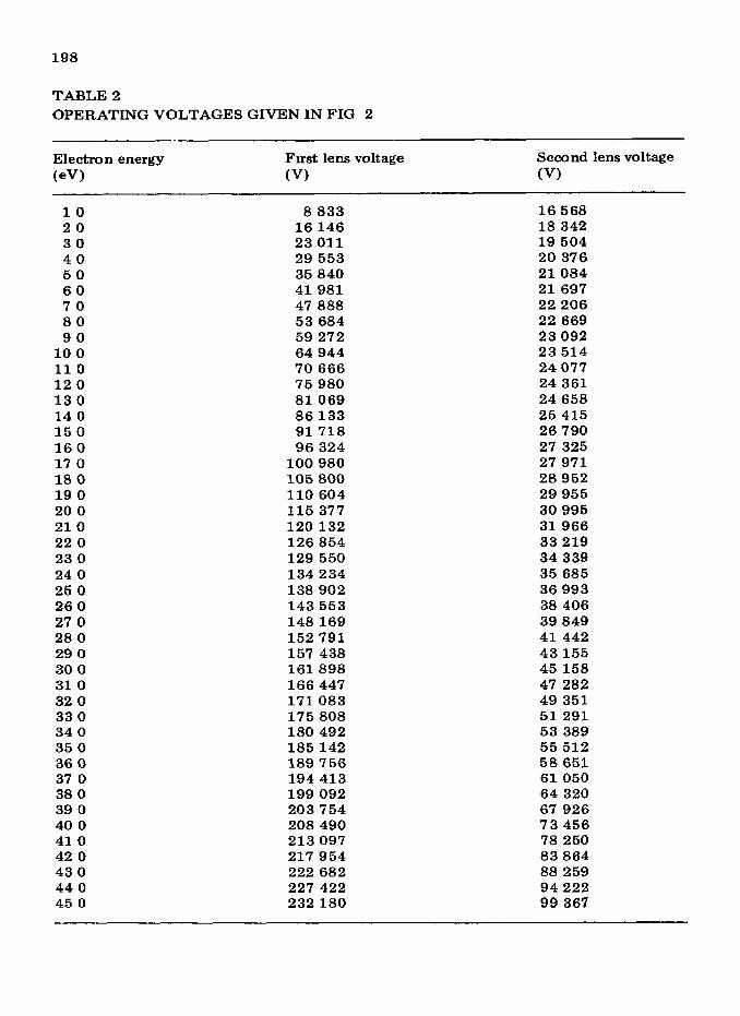
A set of lens voltages which produce a prescribed analyzer resolution as a function of transmitted electron kinetic energy represents an operatmg mode of the analyzer One such operating mode which has been tested (both analytically and experimentally, as described below) 1s given m Table 2 and Fig 2 This mode corresponds to a fixed energy-resolution of -50 meV for mitral kmetlc energies up to 40 eV Correspondmg voltages for the Herzog elements and hemispheres are given by eqns (l)-(3) The output lens voltages (determined using ray-tracing techniques described below) were held fixed at 10 V and 750 V
In the early stages of the lens optunlzatlon process, we calculated the unage properties of the lens system for a fixed kmetlc energy over a wide range of input lens voltages A contour plot of the correspondmg analyzer resolution as a function of the two lens voltages was then made This plot was used to investigate possible solutions to the optlmlzatlon problem and to choose a likely starting pomt for the iterative optunlzatlon process These plots also gave mslght mto the effect of vanatlon of lens voltages on analyzer performance
Ray-tracmg studies of operatmg modes After we had obtamed a set of lens voltages, we wlshed to corroborate the
results of the optlmlzatlon process We wanted to know whether the beam
198
TABLE2
OPERATINGVOLTAGESGIVENINFIG 2
Electron energy Fmst lens voltage (eV) (V)
Secondlensvoltage
(V)
10 8833 16568 20 16146 18 342 30 23011 19504 40 29553 20 376 50 35 840 21084 60 41981 21697 70 47 888 22206 80 53684 22 669 90 59272 23092
100 64944 23514 110 70666 24077 120 75980 24361 130 81069 24658 14 0 86133 25415 150 91718 26790 160 96324 27 325 17 0 100980 27971 180 105800 28952 190 110 604 29955 200 115377 30995 210 120132 31966 220 126854 33219 230 129 550 34339 240 134234 35685 25 0 138902 36993 260 143553 38 406 27 0 148169 39849 280 152791 41442 29 0 157 438 43155 30 0 161898 45158 310 166447 47 282 32 0 171083 49 351 330 175808 51291 340 180 492 53 389 35 0 185142 55512 360 189756 58651 37 0 194413 61050 38 0 199092 64 320 39 0 203754 67 926 400 208 490 73456 410 213097 78 250 42 0 217 954 83864 430 222 682 88 259 440 227 422 94222 450 232180 99 367

199
Fig 2 Plot of mput lens voltages producing a prescribed analyzer resolution, as a func- tlon of transmltted electron kmetw energy, operatmg mode generated by computer pro- gram COMOPT 1171 for fIxed energy-resolution A73 z 50 meV and M = 0 88
would overfill the lens system and whether the beam would have the desn-ed width at the analyzer entrance To answer these questloons, we used an electron trajectory program, SLERT, written by W B Herrmannsfeldt at the Stanford Linear Accelerator Center [19] The program divides an axial plane of the cylmdncal lens system mto a square mesh and fmds the potent& at each of the mesh pomts The program then plots equlpotentlal lmes and traces several rays through the system
Some typical results are shown m Fig. 3. This plot shows traJectones for ZO-eV electrons m an axial plane of the system from the second aperture to the analyzer entrance Beam plots for other enerses differ m (x0 and m the posltlon of the crossover point, which moves nearer the entrance to the capacitor as the electrons’ mltlal kmetlc energy mcreases In all plots the electron beam stayed wlthm the lens boundanes, was focused to the proper diameter at the analyzer entrance, and satisfied eqn (7)
Ray-tracmg analyws of output lens system Electron tralectory plots were also used to determme operatmg voltages for
the electron optics between the Herzog element at the spherical--capacitor exit and the final aperture m front of the channeltron. The final aperture A3 helps to mask the channeltron from electrons emergmg from the capacitor at

200
-I L I 1
0 I 2 3 4 5
DISTANCE (cm]
Fig 3 Results of ray-tracing study for 20eV electrons m an axial plane of the system from the second aperture to the analyzer entrance, traJectorles generated by computer program SLERT [ 19 J for operating mode described m Fig 2
the wrong kinetic energy, or from outslde the output virtual sht The output lens system functions to focus the virtual exit slit at A3 Clearly, some unwanted electrons which scatter mslde the spheres wrll appear at the exit slit image and will contribute an unavoidable background, but the output lens system and aperture A3 mmunlze this effect Trial and error led to the final values of 10 V for the first lens and 750 V for the second
Constructwn detah and geometrrcai parameters The spherical analyzer described m this paper 1s constructed of moly-
bdenum, a metal which IS mechanically stable, non-magnetic, and has a umform contact potential* The analyzer’s spheres are 2 5 and 3 5 cm m radius The mput optics system has a diameter of 1 0 cm and 1s 12.155 cm long The diameter-to-spacmg ratio of all lenses IS IO The first 7.155 cm of the nose cone 1s a field-free drift tube with an aperture at each end The first aperture 1s 0 14 and the second aperture 0 43 cm m diameter When the sample 1s placed 2 0 cm from the analyzer tip, the apertures defme an accep tance half-angle of 1 3 5O (solid angle of 0 0017 steradrans) The analyzer admits electrons from a sample area 0 14 cm m diameter The shape of the nose cone allows it to be posltloned wlthm 8” of an incident photon beam Both the nose cone tip and the second aperture are removable, allowing changes m angular resolution and sample spot size
Test of analyzer performance We tested the analyzer’s performance by recording a UPS spectrum of a
* It has been pointed out to the authors that 5-9 meV resolution can be achreved using 2024 Al and other materials Apparently “patch effects” in contact potentials are not as serious a problem m high-resolution analyzers
201
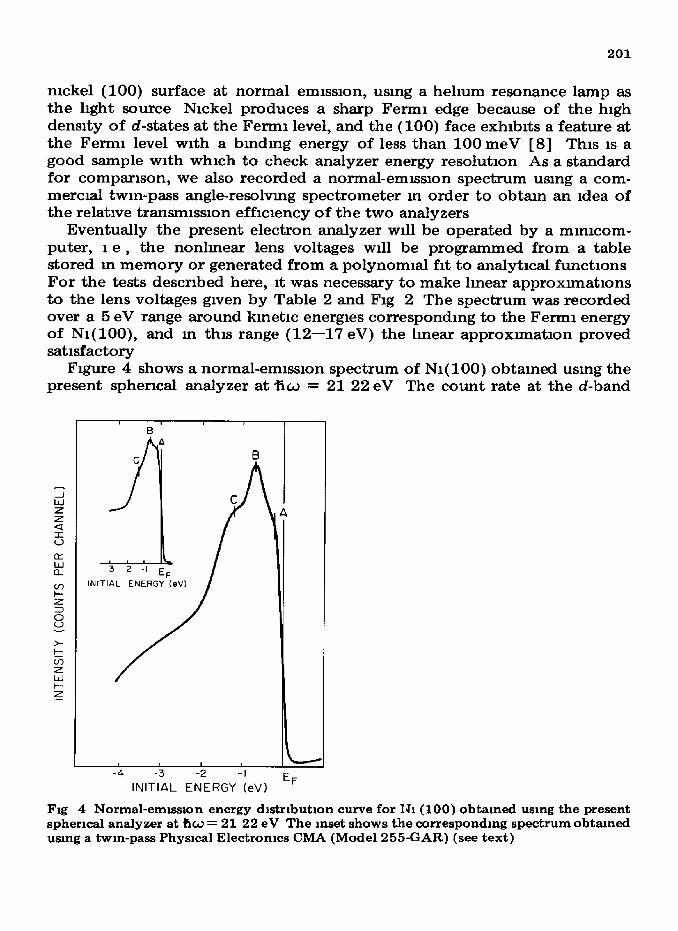
nickel (100) surface at normal emlsslon, using a hehum resonance lamp as the light source Nickel produces a sharp Fermi edge because of the high den&y of d-states at the Fermi level, and the (100) face exhibits a feature at the Fermi level with a bmdmg energy of less than 100 meV [ 81 This 1s a good sample with which to check analyzer energy resolution As a standard for companson, we also recorded a normal-emission spectrum using a com- mercti twin-pass angle-resolving spectrometer m order to obtain an idea of the relative transmlsslon efflclency of the two analyzers
Eventually the present electron analyzer will be operated by a mmlcom- puter, 1 e , the nonlmear lens voltages ~11 be programmed from a table stored m memory or generated from a polynomial fit to analytical functions For the tests described here, it was necessary to make lmear approxunatlons to the lens voltages given by Table 2 and Fig 2 The spectrum was recorded over a 5 eV range around kinetic energies correspondmg to the Fermi energy of Nl(lOO), and m this range (12-17 eV) the linear approxunatlon proved satisfactory
Figure 4 shows a normal-emlsslon spectrum of Nl( 100) obtained using the present spherical analyzer at %J = 21 22 eV The &ount rate at the d-band
--c-e? EF
INITIAL ENERGY (eV)
Fig 4 Normal-emlsslon energy dlstrlbutlon curve for IJ1 (100) obtained using the present spherical analyzer at fic~ = 21 22 eV The inset shows the corresponding spectrum obtained using a twin-pass Physical Electronics CMA (Model 255-GAR) (see text)

202
peak was -2000 counts s-l The angular resolution for this spectrum was +1 3O, the source area was - 1 4 mm m diameter, and the energy resolution was -1OOmeV
For companson, a spectrum obtained using a twin-pass Physical Electronics cyhndncal mm-or analyzer (CMA) (Model 255-GAR) is shown as an inset to Fig 4 The only difference m geometry 1s the incidence angle of the radl- atlon, which 1s dlscussed below For this spectrum the CMA was operated with an angular resolution Aa = 4O and a pass energy of IO V, which ylelded a resolution of -100 meV The count rate for the CMA spectrum was -2500 counts s- 1 Thus the count rate of the spherical analyzer compares quite favorably with that of the CMA, especially when differences of target geometry are considered, 1 e the entrance soled angles and source sizes for the two analyzers The background count rates for both analyzers were -1 count s- 1 , this 1s a typical “dark count” rate for channeltron detectors
The different geometries of the CMA and the spherical analyzer require different target alignments When the CMA was used, the chamber geometry required a 33” angle between the fured light source and the surface normal, the beam of diameter 2 mm proJects onto the sample an oval 3 75mm* m area When the spherical analyzer was used, a 60” angle was necessary be- tween the light and the surface normal, and the light was proJected onto an area of 6 28 mm2 The mtenslty of the light 1s thus much dlmmlshed m the case of the spherical analyzer The CMA has internal apertures 4 mm m diameter, which allows it to sample the entire source regron The spherical analyzer, on the other hand, samples 1 54mm* of the surface, Just one- fourth of the lllummated surface The CMA has an entrance half-angle of 2O, whereas the spherical analyzer’s entrance half-angle 1s 1 34” Thrs means that the spherical analyzer has an entrance solid angle Just 45% of that of the CMA When this 1s combmed with the fraction of the target sampled, It 1s found that the CMA admits nme times as many electrons as does the spherical analyzer, yet the CMA records only 25% more counts per second than the spherical analyzer. (The loss of mtenslty 1s due prlmanly to the presence of s1x grids m the CMA )
The spherical-analyzer spectrum shown m Fig 4 has the same features (labeled A, B, and C) which appear m the CMA spectrum and m spectra reported m the literature [8,20,21] Fairly large varlatlons m mput and out- put lens voltages could be made wlthout producmg changes m the count rate at fured kinetic energy This result suggests that all the voltages are nearly optnnlzed and that the fill factors for the lenses and hemispheres are con- servative It was also found that the second output lens voltage could be decreased from 750 V to 500 V mthout affecting the count rate

203
STJMMARY
We have presented design consrderations, analysis, construction details and tests of an electron energy analyzer developed for use wrth synchrotron radi- ation Source parameters were chosen based on typical output optics charac- tenstic of existing synchrotron facllrty monochromators Initial tests mdi- cate that design goals (small size, high angular and energy resolution, and constant transmission) have been achieved. We plan to report additional operating voltages, ray-tracmg results, and subsequent tests of this analyzer when other operating modes have been analyzed and tested
ACKNOWLEDGMENTS
It 1s a pleasure to acknowledge the help of Dr C E Kuyatt and Mrs. Annija Gale&s of the electron optics group at the National Bureau of Stan- dards for providing the computer code used to obtam input lens operatmg voltages for the analyzer Comments from Dr John D Allen, Jr were help- ful m clanfymg several pomts m our discussion. The skills and efforts of Mr Les Deavers and Mr Bill Killgore, who constructed the analyzer, are also acknowledged This work was sponsored by the National Science Foundation under Grant No DMR-79-23629
APPENDIX I BRIEF DESCRIPTION OF COMPUTER CODE COMOPT
The optlmrzatlon of the present analyzer mput lens system consists of fmdmg a combmatlon of lens positions, diameters, and voltages which properly image the electron beam at the hemisphere midplane The program COMOPT uses a least-squares mmrmization routme to adJust selected lens parameters to produce an image (representing a virtual slit) which yields a prescribed analyzer resolution
Electron lenses, smnlarly to then optical analogs, can be described by two- by-two matrices The subroutme LENS calculates the matrix elements by mterpolatmg from a table on file MATRIX The lens matrices are used to trace several rays from the entrance apertures through the lens system to the analyzer entiance. The beam’s maximum angle of mclmatron and displace ment from the axis are used to characterize the virtual slit and to calculate the correspondmg analyzer energy resolution This calculated resolution IS subtracted from the desired resolutron 111 subroutme FCODE yielding a para- meter called the residual The square of the residual is the function mini- mized by the least-squares routine NLlN4. Every time NLlN4 adJUStS the lens parameters, it calls LENS and FCODE to compare the new residual with that from the prevrous iteratron. This process continues until the residual IS

204
mmmnzed and the lens parameters converge The program then prmts out the results of each iteration wth the focal lengths and other optlcal charac- tenstlcs of the optnnlzed lens system
Inquules about COMOPT and its operation may be directed to the authors of this paper
REFERENCES
1
2 3
4 5
6 7
8
9 10
11 12 13
14 15 16
17
18 19
20 T T Anh Nguyen and R C Cmti, Surf Scl , 68 (1977) 566 21 P Hennann and H Neddermeyer, J Phys F, 6 (1976) L257
B Feuerbacher, B Fltten and R F Wlllls (Eds ), Photoemlsslon and the Electromc PropertIes of Surfaces, Wdey, New York, 1975, Chs l-7 B Feuerbacher and R F Wllhs, J Phys C, 8 (1976) 169 H D Hagstrum, J E Rowe and J C Tracy, Experbmental Methods In Catalytic Research, Vol III, Academic Press, New York, 1976, Ch 2 R H Wllhams, Contemp Phys , 19 (1978) 389 R E Watson and M L Perlman, Science, 199 (1978) 1295, E E Koch, C Kunz and B Sonntag, Phys Rep (Lett Phys. Sect C), 29 (1977) 153 P Planetta and I Lmdau, J Electron Spectrosc Relat Phenom , 11 (1978) 13 D P Woodruff, D Norman, B W Holland, N V Smith, H H Fenell and M M Traum, Phys Rev Lett , 41 (1978) 1130, C H LI and S Y Tong, Phys Rev B, 19 (1979) 1769, G Margarltondo, A D Katnam, N G Stoffel and F Levy, Phys Rev B, 22 (1980) 2777 J L Erskme, Phys Rev Lett , 45 (1980) 1446, E W Plummer and W Eberhardt, Phys Rev B, 20 (1979) 1444 K Horn, M Scheffler and A M Bradshaw, Phys. Rev Lett ,4X(1978) 822 D E Eastman, F J Hlmpsel and J A Knapp, Phys Rev Lett ,40 (1978) 1514, E Dletz, V Gerhardt and C J Maetz, Phys Rev Lett , 40 (1978) 892 N J Shevchlk, Phys Rev B, 16 (1977) 3428 D W 0 Heddle, J Phys E, 4 (1971) 589 E M Purcell, Phys Rev, 54 (1938) 818, K Jost, J Phys E, 12 (1979) 1001, C E Kuyatt and J A Simpson, Rev Scl Instrum., 38 (1967) 103 C L Allyn, T Gustafsson and E W Plummer, Rev Scl Instrum, 49 (1978) 119‘7 G E Thomas and W H Weinberg, Rev Scl Instrum, 50 (1979) 497 P A Sturrack, Static and Dynamic Electron Optics, Cambridge University Press, Cambmdge, 1955 C. E Kuyatt, Electron Optics Lectures, 1967 (unpubhshed notes) Natlonal Bureau of Standards, Washington, DC, see also ref 14 G K Ovrebo, M A Thesis, TJnlverslty of Texas, 1981 W B Herrmannsfeldt, Stanford Linear Accelerator Center, Stanford, CA, 1979, Rep No 226