Embed Size (px)
Citation preview

Protectionand control
Sepam rangeSepam 2000S25, S26 and S35, S36InstallationUseCommissioningGeneral characteristics

1Installation - Use - General characteristics - Testing
Contents
installation 1/1
use - commissioning 2/1
general characteristics 3/1
testing - setting record sheets 4/1
chapter / page

2 Installation - Use - General characteristics - Testing

1/1Installation - Use - General characteristics - Testing
InstallationContents
chapter / page
installation 1/2
use conditions 1/2installation of Sepam 2000 1/2handling, transport and storage 1/2environment of the installed Sepam 2000 1/2
equipment identification 1/3identification of Sepam 2000 1/3accessories supplied with Sepam 2000 1/4optional accessories 1/5
assembly and wiring 1/6dimensions and drilling 1/6assembly 1/6Sepam 2000 components 1/7connections principle 1/7
use and connection of current inputs to CTs 1/8connection of 1 A or 5 A CTs 1/8selection of operating modes 1/8CCA 660 or CCA 650 connector 1/9
use and connection of current inputs to CSPs 1/10CSP current sensors 1/10connection of CSPs 1/10accessories for CSP current sensors 1/11selection of operating modes (microswitches) 1/14
use and connection of split core balance CTs 1/15PO, GO split core balance CTs 1/15assembly of core balance CTs 1/15connection of split core balance CTs 1/15selection of operating mode (microswitches) 1/15
use and connection of CSH 120 and CSH 200 core balance CTs 1/16CSH 120 and CSH 200 core balance CTs 1/16selection of operating mode (microswitches) 1/16connection of CSH 120 and CSH 200 core balance CTs 1/17assembly 1/17wiring 1/17parallel cables 1/17
use and connection of CSH 30 interposing ring CT 1/18CSH 30 interposing ring CT 1/18assembly 1/18wiring 1/18connection to CT with 1 A secondary 1/19connection to CT with 5 A secondary 1/19connection to neutral of 3 CTs 1/19selection of operating mode (microswitches) 1/19
use and connection of ACE 990 interface 1/20connection 1/20characteristics 1/21dimensions 1/21selection of operating mode (microswitches) 1/21assembly 1/21wiring 1/21
connection of voltage inputs 1/22connection of 3 VTs 1/22connection of 3 VTs (residual voltage measurement) 1/22connection of 2 VTs 1/23connection of 1 VT 1/23connection of residual voltage input 1/23connection of 2 phase-to-phase voltages (synchro-check function) 1/24connection of 2 phase-to-neutral voltages (synchro-check function) 1/24connection of 3 VTs or 2 VTs in V arrangement (synchro-check function) 1/24
connection of Pt100 temperature sensors 1/25connection of sensors in 3-wire mode 1/25connection of sensors in 2-wire mode 1/25wiring 1/25

1/2 Installation - Use - General characteristics - Testing
InstallationUse conditions
Installation of Sepam 2000Each Sepam 2000 comes in a single packagewhich contains:c Sepam 2000,c mounting accessories,c connection accessories (connectors).
The other optional accessories come in a separatepackage.
We recommend that you follow the instructions givenin this document for quick, correct installation of yourSepam 2000:c equipment identification,c assembly,c connection of current and voltage inputs, probes,c microswitch setting,c connection of power supply and earth,c checking prior to commissioning.
Handling,transport and storage
Sepam 2000 in its original packaging
Transport:Sepam 2000 may be shipped to any destinationwithout taking any additional precautions by all usualmeans of transport.
Handling:Sepam 2000 may be handled without any particularcare and can even withstand being dropped by aperson handling it (person standing on floor).
Storage:Sepam 2000 may be stored in closed premisesfor several years. Periodic, yearly checkingof the environment and the packaging conditionis recommended.
Sepam 2000 installed in a cubicle
Transport:Sepam 2000 may be transported by all usual meansof transport in the customary conditions used forcubicles. Storage conditions should be taken intoconsideration for a long period of transport.
Handling:Should the Sepam 2000 fall out of a cubicle, check itscondition by visual inspection and energizing. If thereis any doubt, return the Sepam 2000 for checking inthe factory.
Storage:Keep the cubicle protection packing for as long aspossible. Sepam 2000, like all electronic units, shouldnot be stored in a damp environment for more than amonth. Sepam 2000 should be energized as quicklyas possible. If this is not possible, the cubiclereheating system should be activated.
Environment of the installed Sepam 2000
Operation in a damp environmentThe temperature/relative humidity factors must compatible with the unit’senvironmental withstand characteristics.
If the use conditions are outside the normal zone, commissioning arrangementsshould be made, such as air conditioning of the premises.
Operation in a polluted atmosphereSepam 2000 is designed to be used in a clean industrial environment as definedby IEC 60654-4 class 1. A contaminated industrial atmosphere components(such as the presence of chlorine, hydrofluoric acid, sulfur, solvents…)may cause corrosion of the electronic components, in which case environmentalcontrol arrangements should be made (such as closed, pressurized premiseswith filtered air,…) for commissioning.
T (°C)
55
40
35 65 93 95humidity (%)
normal use zone

1/3Installation - Use - General characteristics - Testing
Example of Sepam references:
S36 Sepam 2036
XR type
S substation
03 03
X no communication
(1) Example of labels on the right side panel.
(4) label on the right side of the cartridge.
Date VersionSepam réf. :
Proj réf. :
Drwg n° :
Cubicle ID :
Identificationof a non-standardprogram logicscheme
InstallationEquipment identification
series model type variant communication number operating current auxiliary operatingof ESTOR language sensor supply temperatureboards
S26 LX B = Busbars 1 to 99 X = none 0 = 0 F = French C = CS A = 24/30Vdc N = -5/55°C
S36 LT C = Capacitor J = Jbus 1 = 1 A = English T = CT B = 48/125Vdc
LS G = Generator F = FIP ISIS 2 = 2 I = Italian C = 220/250Vdc
XT M = Motor O = FIP I/O 3 = 3 E = Spanish
KR S = Substation
KZ T = Transformer
ZR R = RTU
YR
XR
LR
SR
SS
TS
TR
CR
CC
Each Sepam is identified by a 14-character reference which describes its hardwareand functional composition in accordance with the chart below.
Identification of Sepam 2000
There are five labels for identifying Sepam 2000:c two labels on the right side panel which givethe product’s hardware features (1),c a label on the front of the cartridge which givesthe functional features (2),c a label on the left side of the cartridge whichincludes its references (3),c a label on the right side of the cartridgewhich may be used to note the referencesof a non-standard program logic scheme (4).
serial n°
model
equipment reference(Sepam, model andapplication)
9641087
MERLIN GERIN
S36 XR *** X2* TAN
origin : FRANCE
SEPAM 2036
(3) example of a label on the left side of the cartridge.
03143764FA-B0-01-9740208
(2) example of a label on the front side of the cartridge.
Sepam model
type of application
program logic diagramreference
S36 : standard SepamXR : modelS03 : type
6 : Sepam S36XR : modelS03 : typeA : EnglishA : rev. level
S36 XR S03
6 XR S03 AA161 SF B
2 2 ESTOR boards
A English
T TC
A 24V
N -5/+55°C
MERLIN GERIN
S36 XR S03 X 2 A TAN 9641087
equipment upgradinglabel
servicing datesboard name
spaces reserved forafter-sales servicingoperationse.g. replacementof an ECM board
spaces reserved forequipment changese.g. addition of anESTOR board

1/4 Installation - Use - General characteristics - Testing
InstallationEquipment identification (cont’d)
Accessories suppliedwith Sepam 2000Each Sepam 2000 comes with the followingaccessories.
CCA 604 connector4-pin connector.Connection of power supply:c screw terminals,c 0.6 to 2.5 mm2 cable(awg 20 to awg 14).
CCA 608 connector (according to type of Sepam)8-pin connector.Connection of VTs:c screw terminals,c 0.6 to 2.5 mm2 cable(awg 20 to awg 14).
CCA 660 or CCA 650 connector for connectionof 1 A or 5 A CTs:c for 4 mm eye lugs,c for max. 6 mm2 cable (awg 10),or CCA 601 BNC/BNC cable,length 5.5 m for connection to the CSP sensors.
CCA 606 connector6-pin connector.Connection of a core balance CT:c screw terminals,c 0.6 to 2.5 mm2 cable(awg 20 to awg 14).
2 Sepam mounting lugs
CCA 621 connector21-pin connector.Connection of logic inputs/outputs,and RTDs:c screw terminals,c 0.6 to 2.5 mm2 cable(awg 20 to awg 14).
CCA 602 cable3 m long cable with connectors supplied withSepam2000 equiped with the Jbus communicationfunctions.

1/5Installation - Use - General characteristics - Testing
Optional accessories
TSM 2001 pocket terminalUsed to make Sepam 2000 settings. It does not havea battery since it is supplied with power bythe Sepam 2000.
AMT 819 plateUsed to mount Sepam 2000 on a 19" rack.
SFT 2801 / SFT 2821 kitThe SFT 2801 software tool installed on a PCmicrocomputer may be used instead of the TSM 2001pocket terminal.c The SFT 2821 software tool installed on a PC maybe used to:v prepare a protection setting file and transfer it toSepam 2000 via the pocket terminal connection,v transfer to a PC, via the pocket terminal connection,all the Sepam 2000 protection settings and storethem in a file.
These software tools are delivered together.
They comprise:c three 3"1/2 diskettes,c an instruction manual,c a connection kit (ACE 900 interface + cord).
In the rest of the document, the term «pocketterminal» refers to both the TSM 2001 pocket terminaland the SFT 2801 kit.
ACE 900 adapter to be connected to the pocket terminal inlet.
AMT 820 shieldUsed to block off the space between Sepam 2000and the edge of the AMT 819 plate.
87
Communication accessoriesRefer to the “RS485 communication networkconnection guide”.
190,5
459
202
11,5
429
482
26,5
37,5 31,5
265,5

1/6 Installation - Use - General characteristics - Testing
B
202201
20 300
222
mounting lugs (x 2)
C A
InstallationAssembly and wiring
Assemblyc Insert Sepam 2000 through the front of the cut-out.Slide it into the cut-out until the front of Sepam 2000is in contact with the mounting plate.
The 2 notches (1) at the base of the Sepam 2000case allow it to hold by its own weight.c Position the 2 lugs (2) in the holes on the topof Sepam. Tighten the threaded studs of the lug.c Make sure not to block the ventilation openings onthe top and bottom of Sepam 2000. Leave a space ofat least 5 cm above and below Sepam 2000.
Drilling diagram
(2)(2)
(1)
Dimensions and drillingSepam 2000 is flush-mounted in a rectangular cut-out.Maximum thickness of mounting plate: 3 mm.
Sepam A (mm) B (mm) C (mm)
S26 * 244 250 264
S36 * 332 338 352
* S25, S35 for earlier versions.

1/7Installation - Use - General characteristics - Testing
Sepam 2000 componentsslot 6 5 4 3 2 1
ESTOR2 (1) ESTOR1 ESB ECM(2) CE40
S26 model*
XT ESTOR ESTOR ESB 3U/Vo _ CE40
LX ESTOR (4) ESTOR (4) ESB _ ECM CE40
LT ESTOR (4) ESTOR (4) ESB 3U/Vo ECM CE40
LS ESTOR ESTOR ESB SONDE ECM CE40
slot 8 7 6 5 4 3 2 1ESTOR2 (1) (3) ESTOR1 ESB 3U/Vo ECM (2) CE40
S36 model*
XR ESTOR ESTOR ESTOR ESB 3U/Vo _ ECM CE40
LR ESTOR ESTOR ESTOR ESB 3U/Vo ECM ECM CE40
LS SONDE ESTOR ESTOR ESB 3U/Vo ECM ECM CE40
SS SONDE ESTOR ESTOR ESB 3U/Vo SONDE ECM CE40
SR ESTOR ESTOR ESTOR ESB 3U/Vo SONDE ECM CE40
KR ESTOR ESTOR ESTOR ESB _ ECM ECM CE40
KZ SONDE ESTOR ESTOR ESB _ ECM ECM CE40
YR ESTOR ESTOR ESTOR ESB _ _ ECM CE40
ZR ESTOR ESTOR ESTOR ESB _ SONDE ECM CE40
TR ESTOR ESTOR ESTOR ESB 3U/Vo 3U/Vo ECM CE40
TS SONDE ESTOR ESTOR ESB 3U/Vo 3U/Vo ECM CE40
CR ESTOR (5) ESTOR (5) ESTOR ESB _ ECMD ECMD CE40
CC ESTOR ESTOR ESTOR ESB ECMD ECMD ECMD CE40(1) the ESTOR board may be installed, depending on the application,(2) or ECA for CSP sensors(3) option for ESTOR board(4) for SX1 and SX2 applications ESTOR boards are not installed.(5) except for S35 CR.
* S25, S35 for earlier versions.
The Sepam 2000 connections are made on the removable connectors locatedon the rear of the device. All the connectors are screw-lockable.
Wiring of screw connectors:c recommended wire fitting:v Telemecanique DZ5CE0155 for 1.5 mm2,v DZ5CE0253 for 2.5 mm2.Stripped length with fitting: 17 mm.Without fitting:c stripped length: 10 to 12 mm,c maximum 2 wires per terminal.The 21-pin connectors must be connected correctly by hand before being lockedby the 2 screws (top/bottom).
Connection principle
SONDE ESTOR ESTOR ESB SONDE3U/V0
SW1
A
B
B
ECM CE40
123456
+
B
(communicationoption)
1
POWER SUPPLY
2
CURRENTINPUT
3
PROBES
4
VOLTAGEINPUT
AAAAAAA
5
INPUTS ANDOUTPUTS
6
INPUTS ANDOUTPUTS
7
INPUTS ANDOUTPUTS
8
PROBES
123456789101112131415161718192021
123456789101112131415161718192021
123456789101112131415161718192021
123456789101112131415161718192021
12345678
123456789101112131415161718192021
1234
V-D
C24
-30
48-1
2522
0-25
0
V-D
C24
-30
48-1
2522
0-25
0
V-D
C24
-30
48-1
2522
0-25
0
V-D
C24
-30
48-1
2522
0-25
0
SW1
SW2
All the Sepam 2000 connection terminals are located on the rear of the device.
The Sepam 2000 boards are fitted into numbered slots on the back;Sepam S26*: 1 to 6,Sepam S36*: 1 to 8.The connections are identified by adding different markings:c slots 1 to 8,c connectors A or B,c terminals 1 to 21.Example: 5 A16slot n° 5, connector A, terminal 16.
Each connector is used for a specific functionalunit identified in the top right-hand corner according to the function:c CE40: auxiliary supply and communication option,c ECM: current sensor (CT) interface,c ECA: current sensor (CSP) interface,c 3U/Vo: voltage sensor interface,c ESB: circuit breaker control interface,c ESTOR: auxiliary control circuit interface,c SONDE: Pt100 temperature sensor interface.The relative position of the units depends on the Sepam 2000 model.

1/8 Installation - Use - General characteristics - Testing
SONDE ESTOR ESTOR ESB SONDE3U/V0
SW1
A
B
B
ECM CE40
123456
+
B
(communicationoption)
1
POWER SUPPLY
2
CURRENTINPUT
3
PROBES
4
VOLTAGEINPUT
AAAAAAA
5
INPUTS ANDOUTPUTS
6
INPUTS ANDOUTPUTS
7
INPUTS ANDOUTPUTS
8
PROBES
123456789101112131415161718192021
123456789101112131415161718192021
123456789101112131415161718192021
123456789101112131415161718192021
12345678
123456789101112131415161718192021
1234
V-D
C24
-30
48-1
2522
0-25
0
V-D
C24
-30
48-1
2522
0-25
0
V-D
C24
-30
48-1
2522
0-25
0
V-D
C24
-30
48-1
2522
0-25
0
SW1
SW2
Selection of operating modes(microswitches)Sepam 2000 has several possible operating modes.The operating mode is selected via microswitcheson the rear of the device. They must be set beforeSepam 2000 is put into service.
The microswitches must be switched while theSepam 2000 is de-energized.The microswitches are hidden by the CCA 660or CCA 650(1) connector once it has been installed.
N.B. Sepam S36 and S35 models LR, LS, KR, KZ,CR and CC have 2 or 3 inputs for connecting CTs.Remember to set the microswitches for the 2 or 3inputs.
for use on the 5 Asecondary circuit.
for measuring residualcurrent by the sum of thecurrents.
SW1
SW2
SW2
SW1
for use on the 1 Asecondary circuit.
SW2
SW1
SW2
SW1
InstallationUse and connection of current inputs to CTs
Connection of 1 A or 5 A CTsThe current transformer (1 A or 5 A) secondarycircuits are connected to the CCA 660 or CCA 650(1)
connector ECM module.This connector contains 3 core balance CTprimary-through adapters to ensure impedancematching and isolation between the 1 A or 5 A circuitsand the Sepam 2000.This connector may be disconnected with the poweron since disconnection does not open the CTsecondary circuits.
L1
Sepam current inputs
L2
L3
P1
P2
B4B1
B5B2
B6B3
DPC
CCA 660or CCA 650
ECM
1 2 3
(1) do not use for S26, S36 or S35 CR.
Microswitch setting
for measuring residual current:c by a CSH core balance CT,c by CT + CSH 30,c by core balance CT + ACE 990,c by CSH 30 via phase CT return
1/9Installation - Use - General characteristics - Testing
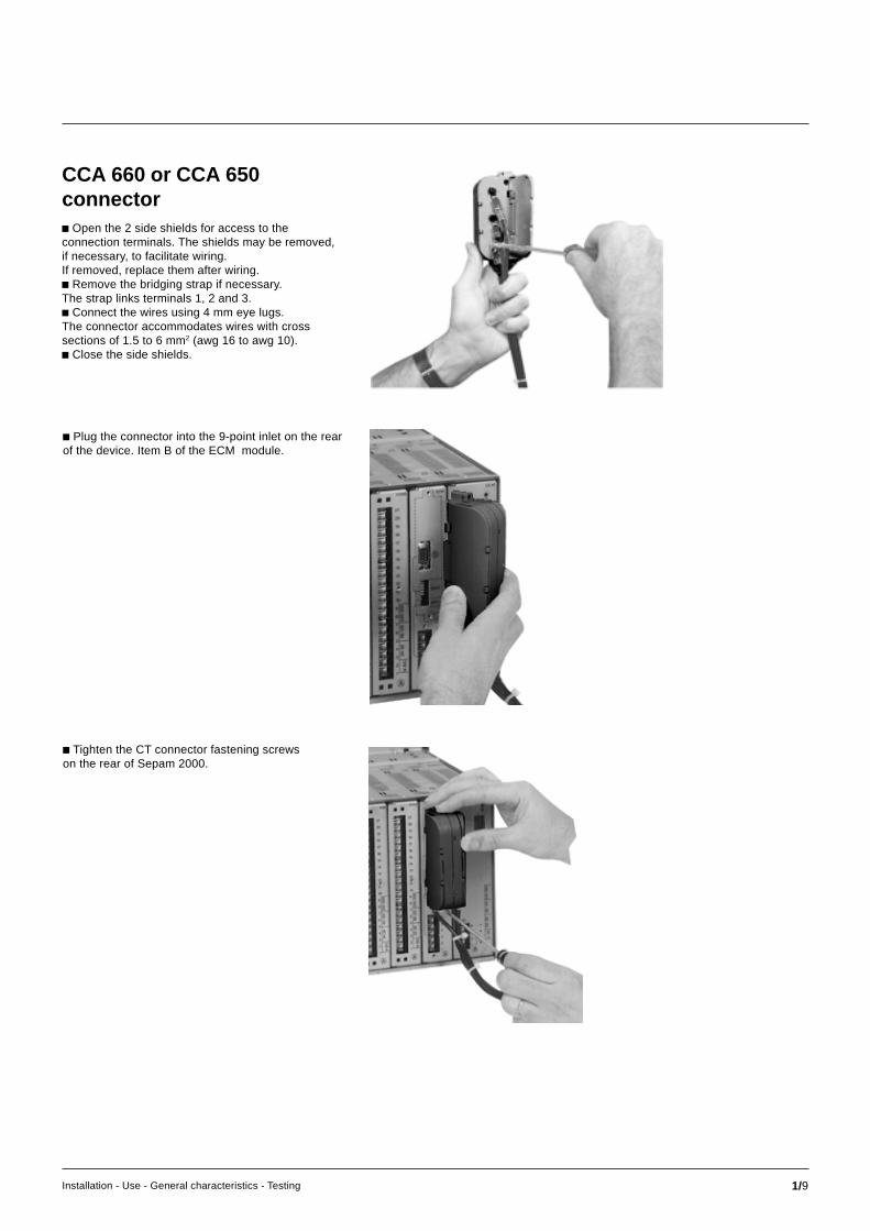
c Plug the connector into the 9-point inlet on the rearof the device. Item B of the ECM module.
c Tighten the CT connector fastening screwson the rear of Sepam 2000.
CCA 660 or CCA 650connectorc Open the 2 side shields for access to theconnection terminals. The shields may be removed,if necessary, to facilitate wiring.If removed, replace them after wiring.c Remove the bridging strap if necessary.The strap links terminals 1, 2 and 3.c Connect the wires using 4 mm eye lugs.The connector accommodates wires with crosssections of 1.5 to 6 mm2 (awg 16 to awg 10).c Close the side shields.

1/10 Installation - Use - General characteristics - Testing
InstallationUse and connection of current inputs to CSPs
Connection of CSPsThe CSP sensors are connected by prefabricatedcoaxial cables, part no. CCA 601, supplied withSepam 2000.
The cables are plugged into:c Sepam 2000, in the BNC inlets on the rear of thedevice, identified L1, L2 and L3 of the ECA modules,c the CSP sensors, in the BNC outlet on each sensor,c the 3 BNC outlets are not equipped with theplugged detector detection system.
The CCA 601 cable shielding is earthed naturallyby the connection to Sepam 2000's BNC inlets.Do not earth by another means.The CSP sensors should be earthed via the earthingscrew on the side of the device.
L1 P1
P2
CCA 601 cable
L2
L3
ECA
1 2 3
CSP current sensorsCSP type current sensors operate according to theRogowski coil principle. They deliver to the secondarycircuit a voltage that is proportional to the derivativeof the primary current.
The CSP sensor – Sepam 2000 assembly forms aconsistent protection and metering system.
The CSP’s special coiling principle and the absenceof a magnetic core gives the sensors the followingproperties:- no saturation: linearity of the curve,- no hysteresis or remanence: transient phenomenaare accurately restituted, without undergoing anydeformation.
This simplifies current sensor specificationand provides a wide dynamic operating range.
L1 P1
P2
ECA
CCA 601 cable CSP sensor
Detailed view ofa connection

1/11Installation - Use - General characteristics - Testing
Accessories for CSPcurrent sensorsThe use of specific CSP sensors requires the useof suitable accessories for injecting currentand recording the current signals from the sensorsecondary circuits.
Accessory connection principle
1 – CSP phase sensor connected to Sepam by 5.5 m cable (CCA 601), the ends of whichare fitted with BNC type connectors (supplied with Sepam).
2 – Sepam phase current input with BNC type connection with a T-shaped connector(delivered with CCA 603 box).
3 – optional CCA 603 connection box installed on front of cubicle and connected to Sepamby 5.5 m cable A (supplied with CCA 603 box).
4 – ACE 907 injection interface connected to CCA 603 box by 1 m cable B(supplied with ACE 907 interface).
5 – ACE 908 recording interface connected to CCA 603 box by cable D and to a recorder 6by 1 m cable E with BNC end (cables supplied with ACE 908 interface).
7 – standard injection box delivering a 1 A current connected to ACE 907 interface by wireswith ø 4 mm fittings not supplied.
N.B. Do not use the ACE 907 interface with 100 A RCAF 1B sensors.
ACE 907
4 7InputOutput C
ACE 908
5
recorder
6Output
Input
E
B
D
ou
SEPAM
A
2
CCA 603
CC
A 6
01
1 CSP
phase
31 Ampinjection box
CCA 603 connection box (3-phase)Box delivered with: three BNC T-connectors, three 1.5 m BNC cables,weight: 200 g
6967.5 6967.567.5
42.523.6
44 46
mounting lug

1/12 Installation - Use - General characteristics - Testing
InstallationUse and connection of current inputs to CSPs (cont’d)
Common characteristicsof ACE 907 and ACE 908 interfaces
Current inputsc Rated current: 1 A.c Impedance i 1 Ω.c Thermal withstand: 80 A 1 s.
Voltage outputsc Impedance i 1 Ω.c Load impedance u 30 kΩ.c Short-circuits tolerated.
Connection
Connection
ACE 907 interface (3-phase)Interface delivered in a case containing:c ACE 907 interface,c one 2 m mains supply cable,c three 1 m BNC cables.
Voltage inputc Rated voltage: 40 mV.c Input impedance u 100 kΩ.c Response in 47 to 63 Hz frequency band(25 to 100 Hz for ACE 908).c Phase shift between input and output +90° ±1%for ACE 907 (-90° +1% for ACE 908).c Module between input and output +6 dB/octave±2% for ACE 907 (- 6 dB/octave ±2% for ACE 908).c Supply voltage: 127 or 230 volts ±15%(250 mA time-delayed fuse).c Operating frequency: 47 to 63 Hz.c Operation: -10°C to + 55 °C.c Storage: -25°C to +70 °C.c No-load consumption: 2 watts.c Weight: 1.5 kg.c Dimensions :v height 70 mm,v width 170 mm,v depth 260 mm.
170
70
260
L2
L1
L3
currentinjection
115/230 VAC
input
L1
L2
L3
654
32
1
789
1011
output
L2
L1
L3
115/230 VAC
input
L1
L2
L3
654
32
1
789
1011
output
ACE 908 interface (3-phase)Interface delivered in a case containing:c ACE 908 interface,c one 2 m mains supply cable,c six 1 m BNC cables.

1/13Installation - Use - General characteristics - Testing
Correspondence between sensor rating, Sepam 2000 SW2 microswitch settingand the position of the “current sensor” selector switch.
CSP network rated current In (in Amps)sensorcurrent range
30-300 A 30 36 45 60 75 90 120 150 180 225 300
160-1600 A 160 192 240 320 400 480 640 800 960 1200 1600
500-2500 A 500 600 750 1000 1250 1500 2000 2500
SW2setting
selector 1 2 3 4 5 6 7 8 5 10 11switch setting
0 10 10 10 10 10 10 10 10 10 10 1
Use of ACE 907 and AC 908c Connect the interface as indicated in the connectiondiagram.c Set the “current sensor” selector switch to theposition that corresponds to the CSP sensor rating.
Examplec CSP 3110 sensor, 30-300 A rating.c Rated current 90 A.
Set the selector switch to position 6.
ACE 907 or ACE 908 interface conversion characteristics
“current sensor” selector switch position
1 2 3 4 5 6 7 8 9 10 11
ACE 907
current input (A)
1 1 1 1 1 1 1 1 1 1 1
maximum permissible current (A)
24 24 24 24 24 24 24 24 24 22 16
output voltage (mV)
40 48 60 80 100 120 160 200 240 300 400
ACE 908
input voltage (mV)
40 48 60 80 100 120 160 200 240 300 400
maximum permissible voltage (V)
3,6 4,3 5,4 7,2 9 10,8 14,4 18 21,6 27 36
output voltage (mV)
100 100 100 100 100 100 100 100 100 100 100
Example (“current sensor” = 6)A 1 A current injected into the ACE 907 interface will be interpreted by Sepamas a 90 A primary current.
For a 90 A primary current, the ACE 908 interface will deliver a 120 mV voltagesignal to the recorder.
PrecautionTo eliminate possible measurement errors, due to ground currents(interface or analyzer supply network ground different from Sepam ground),it may be necessary to supply the ACE 908 interface and the measuring instrumentvia an isolating transformer.

1/14 Installation - Use - General characteristics - Testing
Microswitch setting chartCorrespondence between sensor rating and SW1 and SW2 microswitch settings
Selection of operating modes(microswitches)The operating mode is selected by settingmicroswitches on the rear of the device. They mustbe set prior before Sepam 2000 is switched on, whileit is de-energized.
Set microswitches SW1 and SW2 in accordance withthe chart opposite. They are to be set according to:c the CSP model used (30 A-300 A, 160 A-1600 A,500 A-2500 A),c the rated current of the protected installation,c the earth fault current measurement method(sum or core balance CT).
N.B.: when the rated current of the electricalinstallation to be protected does not appear inthe chart, choose the column that corresponds tothe current rating immediately above.
Example of microswitch settingThis example indicates the microswitch settingin the following case:c network rated current: 160 A.c CSP sensor used: model 160-1600 A.c residual current measured by the sum ofthe 3 phase currents.
0 1
SW2
SW1
1
6
7
12
13
18
12
phase 3
phase 2
phase 1
InstallationUse and connection of current inputs to CSPs (cont’d)
SOM 1 and SOM 2 are parameters to be set in the pocket terminal status menu.In is a parameter to be in the pocket terminal status menu.
SOM1 SOM2
0 10 10 10 10 10 10 10 10 10 10 1
0 1 0 1 0 1 0 1 0 1 0 1
0 1 0 1 0 1 0 1 0 1 0 1 0 1 0 1 0 1 0 1 0 1
CSP network rated current In (in Amps)sensorcurrent range
30-300 A 30 36 45 60 75 90 120 150 180 225 300
160-1600 A 160 192 240 320 400 480 640 800 960 1200 1600
500-2500 A 500 600 750 1000 1250 1500 2000 2500
SW2: phase current
SW1: residual current measured by the sum of the 3 phase currents
SW1: residual current measured by core balance CT
0 1 0 1 0 1 0 1 0 1

1/15Installation - Use - General characteristics - Testing
InstallationUse and connection of split core balance CTs
PO, GO split core balance CTsThese core balance CTs are used when it isimpossible to dismantle the cables.
They are connected to the Sepam 2 A or 30 A ratinginput.
c Transformation ratio 1/470.
dimensions (mm) weight (kg)Ø H L BPO46 72 148 57 1.3GO110 78 224 76 3.2
L(a) (b)
H
ø 5
BL
Ø
Dimensions
Assembly of core balance CTsc Install the core balance CT with the cables groupedin the middle.
c If unwanted tripping occurs due to occasionalcurrent surges or motor starts:a) core balance CT ø = 2 x cable øb) magnetic sleeve - L = core balance CT ø.
Selection of operating mode(microswitches)c Set the corresponding Sepam 2000 switches SW1.The switches concerned are found on the inputmodule.They must be set while Sepam 2000 is de-energized.The microswitches may be hidden by the CCA660or CCA650 connector when it is installed.
SW1
SW2
Connection of splitcore balance CTsTo measure residual current up to 20A,connect the core balance CT to the “2A rating” input.To measure residual current up to 300 A, connectthe core balance CT to the “30 A rating” input.
Cable shield earthing.
A
A5A6
A4A3A2A1
ECA/ECM
30 A rating
DPC
2 A ratingcore bal. CT
S2
S1
P1
P2
1 2 3
REFS2
S1
P1
P2
earthed metalliccable shielding
1 2 3
core balance CT
for measuring residual currentby split core balance CTs

1/16 Installation - Use - General characteristics - Testing
InstallationUse and connection of CSH 120 and CSH 200 core balance CTs
Selection of operating mode(microswitches)c Set the SW1 microswitches on the Sepam 2000.
The microswitches concerned are found on the inputmodule. They should be switched while the Sepam2000 is de-energized.
The microswitches are hidden by the CCA 660 orCCA 650 connector once it has been installed.
CSH 120 and CSH 200core balance CTsThe specific CSH 120 and CSH 200 core balanceCTs are used for direct measurement of earth faultcurrent. The only difference between them is theirinner diameter and they operate with 2 input ratings:c 2 A input rating:settings from 0.1 A to 20 A,c 30 A input rating:settings from 1.5 to 300 A.
Due to the CSHs’ low voltage isolation,they may only be used on cables.
Characteristics:c inner diameter:v CSH 120 : ø 120 mm,v CSH 200 : ø 200 mm.c accuracy: ±5%,c transformer ratio: 1/470,c maximum permissible current: 20kA-1 second,c operating temperature: - 25 °C to +70 °C,c storage temperature: - 40 °C to +85 °C,c maximum metering current Imm .
This is a current value beyond which the SepamCSH core balance assembly saturates.
The user must therefore be careful not to set thetripping threshold higher than Imm.
The maximum metering current depends on:v chosen rating (2 A or 30 A core balance CT),v core balance CT used (CSH 120 or CSH 200),v wiring resistance Rw back and forth between thecore balance CT and Sepam 2000.
0.1 Ω 1 Ω
20 A
80 A
RW
Imm
2 Ω 10 Ω
100 A
300 A
30 A corebalanceCT rating
CSH 200
CSH 120
CSH 120CSH 200
50 A
2 A corebalanceCT rating
The graph above gives the value of Imm
for Rw < 10 Ω.
This graph is used to choose the required core balance CT and wiring.
Example: the high setting of the earth fault protection is 80 A.
Therefore, the 30 A rating of Sepam 2000 is chosen (wiring to terminals 3 and 4of the earth fault connector).
From the graph, it may be deduced that the CSH 120 and CSH 200 are suitableregardless of the wiring resistance, within the limit of 10 Ω.
dimensions (mm) weight (kg)
A B C D E F G H J K L
CSH 120
120 164 26,5 44 190 76 52 40 166 62 35 0.6
CSH 200
200 256 28 46 274 120 90 60 257 104 37 1.4
SW1 for measuring residual currentby a CSH core balance CT.
SW2
C
D
KB
L
ø 5 mounting
ø AF H
J
E
G

1/17Installation - Use - General characteristics - Testing
AssemblyIt is essential to mount the core balance C in the rightdirection in order for the protections to operatecorrectly. The assembly direction should be such thatthe silk-screen printed side of the core balance CT(P2 side) is at the cable end and the unmarked side(P1 side) at the busbar end.
The core balance CT S2 terminal is always connectedto the A4 terminal of the 6-pin connector.
WiringThe CSH 120 or CSH 200 core balance CT isconnected to the CCA 606 6-point connector(item B) of the current input module.
Recommended cable:c sheathed, shielded cable,c min.cable cross-section 0.93 mm2 (awg 18),c resistance per unit length < 100 milli ohms/m,c min. dielectric strenght: 1000 V.Connect the connection cable shielding in theshortest manner possible to the Sepam2000 6-pointconnector.Flatten the connection cable shielding againstthe metal frames of the cubicle.The cable shielding is grounded in Sepam 2000.Do not ground the cable by any other means.
In both cases, group the cables in the middle of thecore balance CT.
Non-conductive binding to hold the cable.
Remember to insert the 3 medium voltagecable-shielding earthing cable through the corebalance CT.
Connection of CSH 120 andCSH 200 core balance CTsTo measure residual current up to 20 A, connect thecore balance CT to the “2 A rating” input.
To measure residual current up to 300 A, connect thecore balance CT to the “30 A rating” input.
Cable shielding earthing.
A
A5A6
A4A3A2A1
ECA/ECM
30 A rating
DPC
2 A ratingcore bal. CT
S2
S1
P1
P2
1 2 3
REF
S2
S1
P1
P2
earthed metalliccable shielding
1 2 3
core bal.
Mounting directly on cable. Mounting on plate or rail.
Parallel cablesIf it is impossible to insert the cables into a CSH 200core balance CT, they may be connected in parallel.c Install one core balance CT per set of cables(max. 5).c Comply with the energy flow direction.c Loss of accuracy:2 core balance CTs = - 10%5 core balance CTs = - 25%.
Ph1Ph2
Ph3
Ph1Ph2
Ph3

1/18 Installation - Use - General characteristics - Testing
InstallationUse and connection of CSH 30 interposing ring CT
CSH interposing ring CTThe CSH 30 interposing ring CT is used as adaptorwhen residual current is measured by a currenttransformer with a secondary circuit (1 A or 5 A).
It acts as an adaptor between the CT and theSepam 2000 residual current input.
It should be connected to the CT input of the Sepam2000 and installed near the corresponding Sepaminput (max. 2 m).
Characteristicsc inner diameter: 30 mm,c accuracy: ± 5%,c transformer ratio: 1/470,c maximum permissible current: 20 kA-1 second,c operating temperature: - 25°C to + 70°C,c storage temperature: - 40°C to + 85°C,c maximum metering current: 10 Ino.
AssemblyThe CSH 30 interposing ring CT is mountedon a symmetrical DIN rail. It may also be mountedon a plate through the mounting holes provided onits base.
Horizontal mounting on DIN rail.
Vertical mounting on DIN rail.
dimensions (mm) weight (kg)A B C D E F30 31 60 53 82 50 0.12
2 ø 4.5
E
D
C
B8
F
5
ø A
2 ø 4.5
21
29
4
16
WiringThe cable must be inserted into the CSH 30interposing ring CT in the right direction in orderfor the directional earth fault protection to operatecorrectly: the cable coming from S2 of the CT must beinserted through the P2 side of the CSH 30 corebalance CT.
The secondary winding of the CSH 30 is connectedto the CCA 606 6-pin connector.Cable to be used:c sheathed, shielded cable,c min. cable cross-section 0.93 mm2 (awg 18)(max. 2.5 mm2),c resistance per unit length < 100 mΩ/m,c min. dielectric strength: 1000 V.Connect the CSH 30 interposing ring CT connectioncable shield in the shortest manner possible(2 m maximum) to the Sepam 2000 6-pin connector.Flatten the cable against the metal frames of thecubicle. The connection cable shielding is groundedin Sepam 2000. Do not ground the cable by anyother means.

1/19Installation - Use - General characteristics - Testing
Connectionto CT with 1 A secondaryc plug into the CCA 606 connector,c wind the transformer secondary wire aroundthe CSH 30 interposing ring CT 5 times.
Selection of operating mode(microswitches)c Set the SW1 microswitches on the Sepam 2000.
The microswitches concerned are found on the inputmodule. They should be switched while the Sepam2000 is de-energized.
The microswitches are hidden by the CCA 660 orCCA 650 connector once it has been installed.
SW1 for measuring residual currentby a CSH core balance CT.
SW2
L1
Sepamcurrent inputs
L2
L3
P1
P2
B4B1
B5B2
B6B3
DPC
CCA 660or CCA 650
1 2 3
ECA/ECM
30 A rating
DPC
2 A ratingcore bal. CT
REF
S2 S1CSH 30core bal. CT
A5A6
A4A3A2A1
1 or 5turns
Connection to neutralof 3 CTsc plug into the CCA 606 connector.c wind the current transformer secondary neutral wirearound the CSH 30 interposing ring CT once(CT with 5 A secondary) or 5 times(CT with 1 A secondary).
Connectionto CT with 5 A secondaryc plug into the CCA 606 connector,c wind the transformer secondary wire aroundthe CSH 30 interposing ring CT once.
P1
P2
DPC P1
P2
S2
S1
S1
S2
5 turns
CSH 30core balance CT
A5A6
A4A3A2A1
ECA/ECM
30 A rating
DPC
2 A ratingcore bal. CT
REF
1 A TC
1 2 3
P1
P2
P1
P2
S2
S1
1 turn
CSH 30core balance CT
S1
S2
A5A6
A4A3A2A1
ECA/ECM
30 A rating
DPC
2 A ratingcore bal. CT
1 2 3
REF
5 A TC

1/20 Installation - Use - General characteristics - Testing
InstallationUse and connection of ACE 990 interface
The ACE 990 is used to match the measurement of aMV core balance CT with ratio 1/n (50 ≤ n ≤ 1500),with that of the residual current input of Sepam 2000.
So as not to downgrade measurement accuracy, theMV core balance CT must be able to supply sufficientpower. The value is given in the chart opposite.
ConnectionTo wire the ACE 990 interface correctly, the followingmust be known:c ratio of the core balance CT (1/n)c core balance CT power,c close approximation of Ino (1) rating, essential forSepam 2000 protection setting.The chart opposite may be used to determine thepossible choices for the connection of the ACE 990interface primary circuit to the Sepam 2000 earthcurrent input, as well as the Ino(1) setting.
The exact value of the rated Ino (1) to be set is givenby the following formula:
Ino = k x number of core balance turns
where k is the factor defined in the chart opposite.
Example:
The core balance CT used has a ratio of 1/400 andpower rating of 2 VA.If the earth fault protection settings are between 0.5 Aand 85 A, the rated Ino(1) used may be 10 A.
This value makes it possible to accurately measurefrom 0.5 A to 100 A.
c Calculate the following ratio:
i.e. 10/400 = 0.025
c In the chart opposite, find the closest value of k.
A close value is k=0.02632.It corresponds to core balance CTs that are supposedto deliver at least 0.1 VA of power.
c In the chart opposite, find the wiring thatcorresponds to the value of k.
The secondary circuit of the MV core balance CTis wired to terminals E2 and E3 of the ACE 990.
The terminals S1 an S2 of the ACE990 should bewired to terminals A2 and A4 of Sepam 2000respectively.
c Calculate the value of Ino to be set:Ino = 0.02632 x 400 = 10.5 A
This value of Ino may be used to monitor a currentbetween 0.5 A and 105 A.
(1) : this is the current value for which the earth faultprotection setting rage extends to between 5% and 1000%of this value, at the most.
E5
E4
E3
E2
E1
S2
S1
ACE 990
A6
A5
A4
A3
ECA/ECM
A2
A1
REF
Example of wiring.
value of k ACE 990 Sepam 2000 Min. power deliveredinput input by MV core balance CT
0.00578 E1 – E5 A2 - A4 0.1 VA
0.00676 E2 – E5 A2 - A4 0.1 VA
0.00885 E1 – E4 A2 - A4 0.1 VA
0.00909 E3 – E5 A2 - A4 0.1 VA
0.01136 E2 – E4 A2 - A4 0.1 VA
0.01445 E1 – E5 A1 - A4 0.4 VA
0.01587 E1 – E3 A2 - A4 0.1 VA
0.01667 E4 – E5 A2 - A4 0.1 VA
0.01689 E2 – E5 A1 - A4 0.4 VA
0.02000 E3 – E4 A2 - A4 0.1 VA
0.02212 E1 – E4 A1 - A4 0.4 VA
0.02273 E3 – E5 A1 - A4 0.4 VA
0.02632 E2 – E3 A2 - A4 0.1 VA
0.02841 E2 – E4 A1 - A4 0.4 VA
0.03968 E1 – E3 A1 - A4 0.4 VA
0.04000 E1 – E2 A2 - A4 0.1 VA
0.04167 E4 – E5 A1 - A4 0.4 VA
0.05000 E3 – E4 A1 - A4 0.4 VA
0.06579 E2 – E3 A1 - A4 0.4 VA
0.08671 E1 – E5 A3 - A4 2 VA
0.10000 E1 – E2 A1 - A4 0.4 VA
0.10135 E2 – E5 A3 - A4 2 VA
0.13274 E1 – E4 A3 - A4 2 VA
0.13636 E3 – E5 A3 - A4 2 VA
0.17045 E2 – E4 A3 - A4 3 VA
0.23810 E1 – E3 A3 - A4 4 VA
0.25000 E4 – E5 A3 - A4 4 VA
0.30000 E3 – E4 A3 - A4 4 VA
0.39474 E2 – E3 A3 - A4 6 VA
0.60000 E1 – E2 A3 - A4 10 VA
close approximation of Inonumber of turns

1/21Installation - Use - General characteristics - Testing
Selection of operating mode (microswitches)c Set the SW1 microswitches on the Sepam 2000.The microswitches concerned are found on the input module. They should beswitched while the Sepam 2000 is de-energized.
The microswitches are hidden by the CCA 660 or CCA 650 connector once it hasbeen installed.
SW1for measuring residual current with core balance CTconnected to ACE 990 interface.
SW2
AssemblyThe ACE 990 interface is mounted on a symmetrical DIN rail.
WiringOnly one core balance CT may be connected to the ACE 990 interface.
The secondary of the MV core balance CT is connected to 2 of the 5 inputsof the ACE 990 interface.
The output terminals of the ACE 990 are connected to the 6-pin connector,CCA 606.
The core balance must be connected to the interface in the right direction in orderfor the directional earth fault and restricted earth fault protections to operatecorrectly.
The cable coming from the core balance terminal marked S1 should be connectedto the terminal with the lowest index.
Cables to be used:Cables to be used:
c cable between core balance CT and ACE 990:v wiring resistance less than 200mΩ/m,v cross-section between 1.5 mm2 (awg 15) and 2.5 mm2 (awg 13)c cable between ACE 990 and Sepam 2000:v shielded and encased (max. length = 2 meters),v cable cross-section between 0.93 mm2 (awg 18) and 2.5 mm2 (awg 13),v resistance per unit of length less than 100 mΩ / m,v minimum dielectric strength: 100 V.Connect the ACE 990 connection cable shielding in the shortest manner possible(max. 2 cm) to the 6-pin connector on the Sepam 2000.Flatten the cable against the metallic frames of the cubicle.The connection cable earthing is grounded in Sepam 2000.Do not ground the cable by any other means.
Dimensions
Weight: 640 gr
ACE 990
7720
S1 S2
E1 E2E3E4E5
50
11
72
25
46 99
11
MERLIN GERIN
c In the E/F sensor headings of the Status menu:v Set the E/F sensor to “Core bal. CT+ACE990”.v Set the Ino parameter as a multiple of 0.1 A according to the calculationrule described earlier.
Characteristicsc Accuracy:v amplitude: ± 1 %,v phase: < 2°.c Maximum permissible current: 20 kA, 1 s(on primary of MV core balance CT with ratio 1/50which does not saturate).c Operating temperature: - 5 °C to + 55 °C.c Storage temperature: - 25 °C to + 70 °C.

1/22 Installation - Use - General characteristics - Testing
SONDE ESTOR ESTOR ESB SONDE3U/V0
SW1
A
B
B
ECM CE40
123456
+
B
(communicationoption)
1
POWER SUPPLY
2
CURRENTINPUT
3
PROBES
4
VOLTAGEINPUT
AAAAAAA
5
INPUTS ANDOUTPUTS
6
INPUTS ANDOUTPUTS
7
INPUTS ANDOUTPUTS
8
PROBES
123456789101112131415161718192021
123456789101112131415161718192021
123456789101112131415161718192021
123456789101112131415161718192021
12345678
123456789101112131415161718192021
1234
V-D
C24
-30
48-1
2522
0-25
0
V-D
C24
-30
48-1
2522
0-25
0
V-D
C24
-30
48-1
2522
0-25
0
V-D
C24
-30
48-1
2522
0-25
0
SW1
SW2
InstallationConnection of voltage inputs
Connection of 3 VTsThis arrangement does not allow residual voltageto be measured by the sum of the 3 phase voltages.
Use the pocket terminal to set the Number parameterof the phase VT ratio heading in the Status menuto 3U.
Connection of 3 VTs (residualvoltage measurement)This arrangement enables Sepam 2000 to measuresystem voltages and calculate the residual voltagebased on the VT secondary voltages.It requires the use of 3 VTs with the primary betweenphase and earth. Terminals 1 and 6 must be strappedin order for Sepam to calculate the residual voltage.
Use the pocket terminal to set the Number parameterto 3U and the Vnso parameter of the phase VT ratioheading in the Status men to 3V.
* S25, S35 for earlier versions.
This concerns the types of Sepam 2000s that havevoltage inputs.Type S26* LT, XT.
S36* XR, LR, LS, SS, SR, TR, TS.The phase and residual voltage transformers (VTs)are connected to the CCA 608 8-pin connectoron the 3U/Vo module. Sepam 2000 can functionwith 1, 2 or 3 VTs.The residual voltage can be measured by twomethods:c calculated by Sepam 2000 based on the phasevoltages,c wired directly to Sepam 2000 from a transformerwith broken delta-star windings.SW1 microswitch setting:The microswitches must be set beforethe Sepam 2000 is energized, accordingto the chosen connection diagram.N.B. Sepam 2000 S36 ou S35 TR and TS modelshave two VT connection inputs. Remember to setthe microswitches for both inputs.
or
A5A6
A4A3A2A1
1
2
3
P2P1
S1 S2
A7A8
DPC
U21U32U13
V2
voltage inputs
SW1 microswitch setting
3U/V0
A5A6
A4A3A2A1
1
2
3
P2P1
S1 S2
A7A8
DPC
U21U32U13
V2
SW1 microswitch setting
voltage inputs
3U/V0

1/23Installation - Use - General characteristics - Testing
Connection of 2 VTsThis arrangement does not allow residual voltageto be measured by the sum method.
Use the pocket terminal to set the Number parameterof the phase VT ratio heading in the Status menuto 3U.
Connection of 1 VTThis arrangement does not allow residual voltageto be measured by the sum method.
Use the pocket terminal to set the Number parameterof the phase VT ratio heading in the Status menu tothe value indicated in the diagram opposite.
Connection of residualvoltage inputThis arrangement is used to connect the residualvoltage measured outside Sepam 2000 viaa transformer with broken delta-star windings.The connection is made on terminals A1 and A2of the 8-pin connector.
Use the pocket terminal to set the Vnso parameterto Uns/e or Uns/3 according to the type of VT used.
A5A6
A4A3A2A1
1
2
3
P2P1
S1 S2
A7A8
DPC
U21U32U13
V2
voltage inputs
SW1 microswitch setting
3U/V0
o
A5A6
A4A3A2A1
1
2
3
P2P1
S1 S2
A7A8
DPC
U21U32U13
Vo
voltage inputsNumber = 1U
SW1 microswitch setting
3U/Vo
o
A5A6
A4A3A2A1
1
2
3
P2P1
S1 S2
A7A8
DPC
U21U32U13
Vo
voltage inputsNumber = V
SW1 microswitch setting
3U/Vo
or
A5A6
A4A3A2A1
1
2
3
P2P1
S1 S2
A7A8
DPC
U21U32U13
V2
voltage inputsNumber = 3U
SW1 microswitch setting
3U/V0

1/24 Installation - Use - General characteristics - Testing
Connectionof 2 phase-to-phase voltages(synchro-check function)The connections are made so that the voltagesapplied to inputs 5 and 4 (U sync 1) and 2 and1 (U sync 2) correspond to the same phases.
example : U21
U21’
This arrangement allows Sepam 2000 to measurevoltage and power.
Use the pocket terminal to set the Number parameterto 1U.
Connectionof 2 phase-to-neutralvoltages(synchro-check function)The connections are made so that the voltagesapplied to inputs 5 and 4 (U sync 1) and 2 and1 (U sync 2) correspond to the same phases.example : V1
V1’
Use the pocket terminal to set the Number parameterto V.
Connection of 3 VTs or 2 VTsin V arrangement(synchro-check function)The connections are made so that the voltagesapplied to inputs 5 and 4 (U sync 1) and 2 and1 (U sync 2) correspond to the same phases.
V1, V2, V3 or U21, U13 and U21.
This arrangement allows Sepam 2000 to measurevoltage and power.
Use the pocket terminal to set the Number parameterto 3U.
InstallationConnection of voltage inputs (cont’d)
A5A6
A4A3A2A1
1
2
3
A7A8
DPC
U21U32U13
U sync 2
voltage inputs
SW1 microswitch setting
3U/V0
U sync 2
A5A6
A4A3A2A1
A7A8
DPC
U21U32U13
SW1
3U/V0
voltage inputs
microswitch setting
U sync 2
A5A6
A4A3A2A1
1
2
3
A7A8
DPC
U21U32U13
SW1
3U/V0
voltage inputs
microswitch setting

1/25Installation - Use - General characteristics - Testing
SONDE ESTOR ESTOR ESB SONDE3U/V0
SW1
A
B
B
ECM CE40
123456
+
B
(communicationoption)
1
POWER SUPPLY
2
CURRENTINPUT
3
PROBES
4
VOLTAGEINPUT
AAAAAAA
5
INPUTS ANDOUTPUTS
6
INPUTS ANDOUTPUTS
7
INPUTS ANDOUTPUTS
8
PROBES
123456789101112131415161718192021
123456789101112131415161718192021
123456789101112131415161718192021
123456789101112131415161718192021
12345678
123456789101112131415161718192021
1234
V-D
C24
-30
48-1
2522
0-25
0
V-D
C24
-30
48-1
2522
0-25
0
V-D
C24
-30
48-1
2522
0-25
0
V-D
C24
-30
48-1
2522
0-25
0
SW1
SW2
Connection of sensorsin 3-wire modeThe following wiring should be done when one of themeasurement channels is not being used.
InstallationConnection of Pt100 termperature sensors
e.g. channel 6 not used.
DPC
Pt100n°5
A21A20A19
A17A16
A13A12A11
A5
A10
A14A15
A18
A7A6
A4
A2
A9A8
A3
A1
Pt100n°4
Pt100n°3
Pt100n°2
Pt100n°1
sensors
A17
A16
A18
This concerns the types of Sepam 2000 that haveinputs for Pt100 type temperature sensors.
The Pt100 sensors are connected to the CCA 62121-pin connector on the SONDE module.
Connection of sensors in 2-wire modeThis connection mode should only be used when it is impossible to use the 3-wiremode (e.g. existing cable) since it introduces a substantial measurement error.
The following wiring should be done when one of the measurement channels is notbeing used.Example: channel 6 not used.
A17
A16
A18
WiringIt is preferable to use shielded cables. The useof unshielded cables may cause measurement errors, the size of which dependson the degree of electrical and magnetic disturbance in the cable surroundings.Only connect the shielding at the Sepam 2000 end: connect the connection cableshielding in the shortest manner possible to the corresponding terminals of the 21-pin connector.Do not connect the shielding at the temperature sensor end.Recommended cross-sections according to distance :c up to 100 m > 1 mm2, awg 16,c up to 300 m > 1.5 mm2, awg 14,c up to 1 km > 2.5 mm2, awg 12.
DPC
Pt100n°5
A21A20A19
A17A16
A13A12A11
A5
A10
A14A15
A18
A7A6
A4
A2
A9A8
A3
A1
Pt100n°4
Pt100n°3
Pt100n°2
Pt100n°1
sensors
1/26 Installation - Use - General characteristics - Testing
SONDE ESTOR ESTOR ESB SONDE3U/V0
SW1
A
B
B
ECM CE40
123456
+
B
(communicationoption)
1
POWER SUPPLY
2
CURRENTINPUTS
3
PROBES
4
VOLTAGEINPUTS
AAAAAAA
5
INPUTS ANDOUTPUTS
6
INPUTS ANDOUTPUTS
7
INPUTS ANDOUTPUTS
8
PROBES
123456789101112131415161718192021
123456789101112131415161718192021
123456789101112131415161718192021
123456789101112131415161718192021
12345678
123456789101112131415161718192021
1234
V-D
C24
-30
48-1
2522
0-25
0
V-D
C24
-30
48-1
2522
0-25
0
V-D
C24
-30
48-1
2522
0-25
0
V-D
C24
-30
48-1
2522
0-25
0
SW1
SW2
ESB
DPCA21
A20
A19
A17
A16
A13
A12
A11
A5
O2
A10
A14
A15
A18
O1
A9
A8
A7
A6
A4
A3
A2
A1
l2
l1
CDG
A
InstallationConnection of power supply and logic inputs and outputs
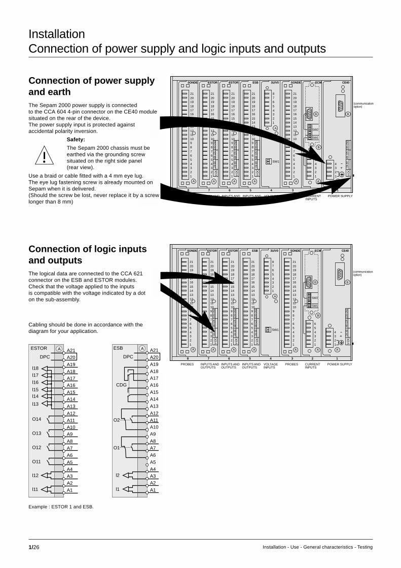
Example : ESTOR 1 and ESB.
ESTOR
DPCA21
A20
O11
A7
A4
A3
A2
A1
l12
l11
A8
A5
A6
A10
A9
A12
A11
O12
O13
O14
A13
A19
A17
A16
A18
A14
A15
l13
l14l15
l16
l17
l18
A
Connection of power supplyand earthThe Sepam 2000 power supply is connectedto the CCA 604 4-pin connector on the CE40 modulesituated on the rear of the device.The power supply input is protected againstaccidental polarity inversion.
Safety:
The Sepam 2000 chassis must beearthed via the grounding screwsituated on the right side panel(rear view).
Use a braid or cable fitted with a 4 mm eye lug.The eye lug fastening screw is already mounted onSepam when it is delivered.(Should the screw be lost, never replace it by a screwlonger than 8 mm)
Connection of logic inputsand outputsThe logical data are connected to the CCA 621connector on the ESB and ESTOR modules.Check that the voltage applied to the inputsis compatible with the voltage indicated by a doton the sub-assembly.
Cabling should be done in accordance with thediagram for your application.

1/27Installation - Use - General characteristics - Testing
SONDE ESTOR ESTOR ESB SONDE3U/V0
SW1
A
B
B
ECM CE40
123456
+
B
(communicationoption)
1
POWER SUPPLY
2
CURRENTINPUTS
3
PROBES
4
VOLTAGEINPUTS
AAAAAAA
5
INPUTS ANDOUTPUTS
6
INPUTS ANDOUTPUTS
7
INPUTS ANDOUTPUTS
8
PROBES
123456789101112131415161718192021
123456789101112131415161718192021
123456789101112131415161718192021
123456789101112131415161718192021
12345678
123456789101112131415161718192021
1234
V-D
C24
-30
48-1
2522
0-25
0
V-D
C24
-30
48-1
2522
0-25
0
V-D
C24
-30
48-1
2522
0-25
0
V-D
C24
-30
48-1
2522
0-25
0
SW1
SW2
InstallationConnection of the Jbus/Modbus communication coupler
Sepam 2000 can be equiped, as an option, with acommunication coupler situated on the CE40 module.Please refer to the “RS 485 network connectionguide” and “Sepam 2000, Jbus/Modbuscommunication” documents for commissioninginstructions and the choice of accessories.

2/1Installation - Use - General characteristics - Testing
Use - commissioningContents
use - commissioning 2/1
description / use 2/2front face 2/2TSM 2001 pocket terminal 2/4
use (current operation) 2/6energizing 2/6operation via the front face or the TSM 2001 pocket terminal 2/6operation via the TSM 2001 pocket terminal alone 2/7clearing measurements 2/8annunciation 2/8list of messages 2/8
commissioning 2/10checking prior to commissioning 2/10commissioning using the pocket terminal 2/10parameter and setting errors 2/11status menu parameters chart 2/11microswitch SW1 and SW2 settings 2/12protection 2/12protection function setting ranges 2/14program logic and annunciation 2/18resource and program logic chart 2/18connection of logic inputs 2/18connection of logic outputs 2/18time delay settings 2/22disturbance recording 2/40
maintenance 2/41list of Sepam 2000 self-tests 2/41indicators lamps and display messages 2/42communication indicator lamps 2/43unwanted tripping, no tripping 2/43tests 2/43Sepam replacement 2/43
Sepam 2000 identification 2/44Sepam identification using the pocket terminal 2/44compatibility of types and models 2/45
Sepam 2000 documentation 2/47
password 2/48
use of the password 2/48
modification of the password 2/48
loss of the password 2/48
chapter / page

2/2 Installation - Use - General characteristics - Testing
Status indicators 1 :c green on indicator lamp shows that Sepam 2000 is energized,c red trip indicator lamp: Sepam has tripped the circuit breaker after detecting afault. A related alarm message indicates the cause of tripping,c red indicator lamp shows internal Sepam faults. All the output relays aredropped out (fail-safe position). (Refer to the chapter on maintenance),c yellow I on indicator lamp and green O off indicator lamp show the positionof the circuit breaker:v I = circuit breaker closed,v O = circuit breaker open.
Use - commissioningDescription/use
Standard model: Sepam 2000 S36 or S35 (for all types).
Compact model: Sepam 2000 S26 or S25 (for certain types).
Your Sepam 2000 is a multifunction,microprocessor-based device which includesin the same case:c control and monitoring of the associated circuitbreaker or contactor,c measurement of electrical variables,c display of operating messages,c protection of the network and the drives it supplies.Sepam 2000 may be equiped (as an option)with a communication link with the remote monitoringstation. There are two models of Sepam.
Front face
1 status indicators2 display3 keys for access to measurement and alarm processing4 cartridge5 pocket terminal socket

2/3Installation - Use - General characteristics - Testing
Cartridge 4The cartridge contains the information required for Sepam operation, such as:c settings,c stored data,c program and annunciation logic
Pocket terminal socket 5This socket is used to connect the TSM 2001 pocket terminal or the ACE 900interface to the SFT 2801 / SFT 2821 software (PC link).
Display 2The display unit indicates:c measurements,c operating messages.
Keys for access to measurements and alarmprocessing 3c metering keyThe measurements may be accessed by pressingthe A, V/Hz, W/ϕ, Wh/°C metering keys.Each key provides access to a set of measurementsaccording to the ring method.
When a measurement is not available in a typeof Sepam, ----------- is displayed,c clear key:this key erases the stored value being displayed(reset):- max. current demand IM1, IM2, IM3,- tripping currents TRIP1, TRIP2, TRIP3, TRIP0,- peak demand power PM, QM,c alarm processing keyv alarm key:each time tripping or another event occurs, an alarmmessage stored in a list of alarms is displayed.The most recent message appears on the display.This key provides access to step by step readingof the list of stored alarm messages.The previous message may be displayed by pressingthis key.Display of: ----------- indicates the end of the listof alarm messages.
v reset key:
The protections trigger circuit breaker tripping and display of the relatedmessages.The red trip indicator lights up.After the fault has been cleared, the user presses the reset key to acknowledge.The trip indicator is extinguished, the list of alarms is erased and the device canbe closed. The reset key is disabled until the fault has been cleared.
Example: current measurement
I1
I2
I3
IM1
IM2
IM3
TRIP1
TRIP2
TRIP3
TRIP0
key- A -

2/4 Installation - Use - General characteristics - Testing
P/Select:
Add. reading
Status
About Sepam
Use - commissioningDescription/use (cont'd)
The TSM 2001 pocket terminal and the SFT 2801 software for PC operate in thesame way.
The pocket terminal provides access to allthe Sepam 2000 information, such as:c current measurements,c operating assistance messages,c protection settings.
The pocket terminal is supplied with power by Sepam 2000 and does not requireany batteries; it can be connected with the power on.The pocket terminal beeps when it is connected.The main menu appears (if nothing is displayed, check the brightness adjustmentusing the key).The user may access the various items of information from three menu levels.A menu may comprise several pages.To access a menu, simply position the blinking cursor on the desired line and pressthe enter key.The first line of the menu contains the name of the current menu or function.Indication of P/ at the head of the menu indicates that the user has enteredthe password.
Role of the keys:c the pocket terminal beeps when the user presses a key that is disabled.c the menu key is used to display the previous menu,c the and keys are used to move the c cursor one line up or down in a menu.To move to the next screen of a menu, the user simply positions the cursor on thelast line and presses the key.
To move to the previous screen of a menu, the user simply positions the cursor onthe second line and presses the key,c the code key is used to enter and exit the parameter setting mode,c the numeric and . keys are used to enter settings and the password,c the units key is used to change setting unit multiplying factors (e.g. A, kA,...),c the data+ and data- keys are used to select values from preset data lists.These lists are used when only a limited number of values may be usedfor a parameter, e.g. network frequency value,c the clear key is used:v to clear error messages,v to call back a previous setting value during data input,v to reset tripping currents and maximum demand readings to zero,c the enter key is used to confirm a menu selection or to confirm all the settingsfor a function.
N.B. The first line always contains the name of the current menu or function.
P/Select:
Metering
Protection
Program logic
TSM 2001 pocket terminal /SFT 2801
2
1 4-line display
data entry keypad

2/5Installation - Use - General characteristics - Testing
P/ADD. READING Residual I Residual V I and V start
P/I RESIDUAL CURRENTI0 = 12.3 A
Enter
Menu
Enter
Menu
Enter
Menu
Enter
Menu
Enter
Menu
Menu Menu Menu Menu Menu
Menu
Enter
Enter
Menu
Menu
Enter
P/I PHASE CURRENT I1 = 453 A I2 = 452 A I3 = 453 A
P/Select: Metering Protection Program logic
P/Select: Add. reading Status About Sepam
P/PROGRAM LOGIC Logic input Logic output Monostable relay
P/STATUS Rated frequency Phase CT ratio E/F Sensor
P/PROGRAM LOGIC M01PA001 CAT H NOL APPLICATION MOTOR
P/ABOUT... SFT 2800 Program logic Communication
= 500 A= 450 A= I1-I2-I3
P/PHASE CT RATIO In Ib Number
P/PROTECTION 50-51 50N-51N 49
F011F081F431
P/METERING Phase current System voltage Power & pwr factor
P/50-51 Curve Is T
F011= Definite= 1,2 kA= 300 ms
P/LOGIC OUTPUT 01-02 011-014 021-024
= 10= 0000= 1010
Example of use of the SFT 2801 software with Sepam 2000.

2/6 Installation - Use - General characteristics - Testing
Press Menu key
to get
the main menu
Use - commissioningUse (current operation)
Operation via the front face or pocket terminal
EnergizingSepam is energized when operating normally.In the event of re-energizing after a break in theauxiliary power supply, Sepam 2000 automaticallyrestarts according to the following sequence,which lasts about 5 s:c green on and red indicators light up,c beep (if the pocket terminal is connected),c extinction of the red indicator,c resetting of watchdog contact,c testing of display:
0,0,0,0,0,0,0,0,0,0,0 then ***********, then I1 = 0.0 A
c breaker position indicator lights up,c display of the first message.Sepam is then in operation. If the pocket terminal is connected, it displays:
Sepam 2000 performs the functions of a precision measurement and alarmprocessing unit. The values are displayed directed with the related uit A, kA, etc.The messages clearly worded. There are two ways of operating the device:c via the front face (metering, annunication keys),c via theTSM2001 pocket terminals (using menus).Whenever a measurement is not available in the user's type of Sepam,-----------is displayed.
functions key TSM menu desig. description range accuracy comments
phase current A metering I1 measurement of each 0 to 24In ±0.5% value depends onI2 phase current associated CTI3
maximum current A metering IM1 measurement of the 0 to 24In ±0.5% the value isdemand IM2 average current in periodically
IM3 the 3 phases recalculated.Value set in Statusmenu to 5, 10, 15, 30or 60 mnRESET: clear key
tripping A metering TRIP1 measurement of phase 0 to 24In ±5% RESET: clear keycurrent TRIP2 and earth currents at
TRIP3 the time of the trippingTRIP0 order
voltage V/Hz metering V1,V2,V3 measurement of 0 to 1.5Un ±0.5% Value depends onphase-neutral and associated VT
U21,U32,U13 phase-phase voltages
frequency V/Hz metering F measurement of 45 to 65 Hz ±0.02 Hz measured onfrequency input U21
real power W/ϕ metering P measurement of 0 to 999 MW ±1% positive or negativereal power
reactive W/ϕ metering Q measurement of 0 to 999 MVAr ±1% positive or negativepower reactive power
power factor W/ϕ metering PF measurement of -1 to +1 0.01 P sign inductive orpower factor capacitive
maximum real W/ϕ metering PM measurement of the 0 to 999 MW ±1% same remarks asand reactive greatest average for maximum currentpower demand W/ϕ metering QM power value 0 to 999 MVAr ±1% demand
real and reactive Wh/°C metering +MWH measurement of 0 to 99999.99 ±1% for the displayenergy real energy consumed
Wh/°C metering +MVRH measurement ofreactive energy consumed
Wh/°C metering -MWH measurement of real 0 to 280x106 ±1% for the pocketpower supplied terminal
Wh/°C metering -MVRH measurement of reactive values are stored inpower supplied the event of a power
failure
temperatures Wh/°C metering T1, T2 measurement of -50° to 250°C ±1°C operates with Pt100T3, T4 temperatures sensorsT5, T6
N.B. No values are displayed when the measurement is less than 1.5% of the rated value.

2/7Installation - Use - General characteristics - Testing
Operation via the pocket terminal alone
function pocket terminal menu name description range accuracy
earth fault add. reading Io measurement of residual current 0 to 10Ino ±5%residual current
residual voltage add. reading Vo measurement of residual voltage 0 to 1.5Un ±5%residual voltage
start current add-reading Tstart start time 0 to 999 s ±5%
and time start current & time Imax maximum start current 0 to 24In ±5%
Istart instantaneous current if > 1.2Ib 0 to 24In ±5%
cumulative breaking add. reading number of breaking operation 5% In at 24 In ±10%current Nb of operation in (kA)2 cumulative value of (kA)2
differentiel current add. reading Idiff I measuremnt of 0 to 24 In ±5%and through current Idiff & Ithrough Ithrough differential and through currents
true rms current add. reading Irms measurement of true rms current 0 to 4 In +1%Irms up to harmonic 21
phase rotation protection Vd measurement of positive seq. voltage 0 to 100% Vn ±5%pos. seq. U/V1 indication of "inverse" if the network
is rotating backwards
number of starts protection Tblock blocked start time 0.5 to 655 s
nb. starts Nrest number of starts allowed 1 to 60/hour
thermal overload protection thermal E % heat rise 0 to 999% ±2%
unbalance ratio protection unbalance Ii negative current 0 to 1Ib ±5%
directional protection Phi 1 phase shift between I1 and U32 0° to 360° ±3° at In,Un
overcurrent directional O/C Phi 2 phase shift between I2 and U13 0° to 360° ±3° at In,Un
Phi 3 phase shift between I3 and U21 0° to 360° ±3° at In,Un
directional earth fault protection directional E/F Phi 0 phase shift between Io and Vo 0° to 360° ±3°name description zero reset (1)
general counters for all types of application
C1 number of closing operations performed by the breaking device Kp19
C2 number of phase-to-phase short-circuit fault trips Kp20
counters for the motor - generator applications
C3 number of hours of motor running Kp21
C4 number of minutes associated with running hours counter C3
counters for the capacitor application with capacitor control
C4 capacitor 1 running hours counter Kp21
C5 capacitor 2 running hours counter Kp21
C6 capacitor 3 running hours counter Kp21
counters for the substation application with recloser function
C3 number of earth fault trips Kp20
C4 number of successful reclosing operations Kp22
C5 number of cycle 1s performed Kp22
C6 number of cycle 2s performed Kp22
C7 number of cycle 3s performed Kp22
C8 number of cycle 4s performed Kp22
(1) requires use of the password

2/8 Installation - Use - General characteristics - Testing
Clearing measurementsc maximum phase current demand.To reset to zero:v press clear on the pocket terminal if the maximumcurrent demand readings are displayed,v press clear on the display if at least one maximumdemand is displayed,c tripping current (phase or earth).To reset to zero:v press clear on the pocket terminal if all the trippingcurrents are displayed,v press clear on the display if at least one trippingcurrent is displayed,c maximum real and reactive power demands.To reset to zero:v press clear on the pocket terminalif all the maximum demands are displayed,v press clear on the display if at least one maximumpower demand is displayed,
N.B.Zero resetting of the maximum demand readingsallows calculations to be started for a new integrationinterval.c motor heat rise.To reset to zero, press the clear key on the pocketterminal if the heat rise measurement is displayedand if the user is in parameter setting mode,c number of starts.To reset, press the clear key on the pocket terminalif the blocked time is displayed and if the useris in parameter setting mode.The resetting of these functions alters the normaloperation of the protections (changes their priorstatus).
AnnunciationWhen an event is detected by Sepam 2000,an operating message appears on the display.The messages are stored in a list of alarms and maybe reviewed in chronological order of appearance,starting with the most recent, by pressing thealarm key.
Beware:pressing the reset key will erase the contentsof any list of alarms.
List of messages(according to the type of Sepam).
Use - commissioningUse (current operation) (cont’d)
message (1) type meaning
? CONTROL ? A tripping order discrepancy
? CONTROLX ? P capac capacitor x switch control supervision
RECEIVE BI A blocking input
EXT. TRIP A tripping by external protection
PRESSURE A breaking pole pressure fault
INST O/C A reclose instantaneous overcurrent
INST E/F A reclose instaneous earth fault
CYCLE 1 A reclose cycle 1 in progress
CYCLE 2 A reclose cycle 2 in progress
CYCLE 3 A reclose cycle 3 in progress
CYCLE 4 A reclose cycle 4 in progress
SUCCESSFUL A reclose successful reclosing (fault cleared)
DEFINITIVE A reclose definitive tripping (fault not cleared)
TR.GAS A gas detector (alarm or tripping)
DISCHARGE A time-delayed energizing
OPG INHIB A inhibition of disturbance recording
RESTART A staggering of restarts
TX AL/TRIP A transformer fault (alarm or tripping)
START INHIB A motor restart inhibited
CARTRIDGE M cartridge and Sepam not compatible
CONNECTOR M unplugged connector
MAINTENANCE M internal Sepam fault
M.CARTRIDGE M internal cartridge fault
RTD FAULT M PTC or PT100 sensor fault
LOCK. ROTOR P locked rotor
BUCHHOLZ P buchholz, alarm or tripping
LOAD SHED. P positive sequence undervoltage (or I12)
LONG START P excessive starting time
UNBALANCE P negative sequence / unbalance
UNBAL.ALARM P capac neutral to neutral unbalance, alarm
UNBAL.TRIP P capac neutral to neutral unbalance, tripping
UNBAL. ALARM 1 P neutral to neutral unbalance capacitor 1, alarm
UNBAL. ALARM 2 P neutral to neutral unbalance capacitor 2, alarm
UNBAL. ALARM 3 P neutral to neutral unbalance capacitor 3, alarm
UNBAL. TRIP 1 P neutral to neutral unbalance capacitor 1, tripping
UNBAL. TRIP 2 P neutral to neutral unbalance capacitor 2, tripping
UNBAL. TRIP 3 P neutral to neutral unbalance capacitor 3, tripping
LOM 1 P rate of change of frequency, setting 1
LOM 2 P rate of change of frequency, setting 2
GEN. DIFF. P generator differential
MOTOR DIFF. P motor differential
FIELD LOSS P reactive overpower (de-energizing)
FRAME LEAK P frame leak
OVERFREQ.1 P frequency too high, setting 1
OVERFREQ.2 P frequency too high, setting 2
OVERCURRENT P phase overcurrent
LOW O/C P phase overcurrent, settings 1 and 3
O/C V REST P voltage restrained overcurrent
DIR. O/C P directional phase overcurrent
typeA = automation (program logic)P = protectionM = maintenance
(1) If your Sepam 2000 has been customzied, other messagesmay appear.Please refer to the information package providedby your OEM.

2/9Installation - Use - General characteristics - Testing
message (1) type meaning
FAULT SSL default SSL reception
HIGH O/C P phase overcurrent, settings 2 and 4
NEUTR. O/C1 P neutral overcurrent, setting 1
NEUTR. O/C2 P neutral overcurrent, setting 2
EARTH FAULT P earth fault
DIR. E/F P directional earth fault
OVERVOLT. 1 P overvoltage, setting 1
OVERVOLT. 2 P overvoltage, setting 2
O/VOLT.X By P overvoltage setting x busbar y
N VOLT DISP P neutral voltage displacement
EXT. STOP. A gen emergency generator shutdown
EXT. LOCK A gen coupling inhibited
E/F P earth fault current Io’
FIELD STOP A gen generator de-energizing order
FREQ. GAP A gen frequency variance greater than set point,synchro-check protection
ANGLE GAP A gen angle variance greater than set point,synchro-check protection
VOLTAGE GAP A gen voltage variance greater than set point,synchro-check protection
SYNCHRO. A search for synchronism
STOP SYNC. A stopping of search for synchronism
U.SYN1 FAIL A VT circuit 1 open
U.SYN2 FAIL A VT circuit 2 open
UNDERFREQ.1 P frequency too low, setting 1
UNDERFREQ.2 P frequency too low, setting 2
UNDERFREQ.3 P frequency too low, setting 3
UNDERFREQ.4 P frequency too low, setting 4
U/CURRENT P phase undercurrent
UNDERVOLT. P undervoltage
UNDERVOLT.1 P undervoltage, setting 1
UNDERVOLT.2 P undervoltage, setting 2
UNDERVOLT’1 P undervoltage, setting 1
UNDERVOLT’2 P undervoltage, setting 2
U/VOLT.X By P undervoltage setting x busbar y
STARTS/HOUR P number of allowed starts reached
TR PRESSURE P transformer pressure fault
REF P restricted earth fault
REF’ P restricted earth fault
REVERSE P. P reverse real power
ROTATION P phase rotation direction fault
RTD XX P temperature fault (alarm or tripping) on RTD n°XX
THERMAL P thermal overload (alarm or tripping)
LATCH. CTRL P&T latching contactor
IMP. CTRL P&T contactor with impulse orders
PERM. CTRL P&T contactor with latched orders
U/V RELEASE P&T circuit breaker with undervoltage release coil
SHUNT-TRIP P&T circuit breaker with shunt-trip coil
! ERROR ! P&T error in command parameter settingtypeA = automation (program logic)P = protectionP&T = control function parameter setting test(1) If your Sepam 2000 has been customzied, other messages may appear.Please refer to the information package provided by your OEM.

2/10 Installation - Use - General characteristics - Testing
Use - commissioningCommissioning
Checking priorto commissioningThese operations must be carried out beforeSepam 2000 is energized.
Checks:c supply voltage
Ensure that the cubicle auxiliary supply voltagematches Sepam 2000's operating voltage. It isindicated on the rear of the device, beside the powersupply connector, by a dot in the voltage box,
ExampleS26L X on the cartridgelabel should matchS26LX on the Sepamlabel.
(1) Refer to “Installation” chapter.(2) All parameters and settings must be based on a network discrimination study that is to becarried out prior to commissioning.(3) This mode is automatically cancelled if no keys are pressed for about 1 minute. It may becancelled manually by pressing the Code key.
c earthingCheck that the Sepam 2000 chassis is earthed bythe ground nut situated on the Sepam side panel,on the power supply side.Check that the screw is tightened.c cartridgev Check that the cartridge is in its slot behind the frontwicket door. To do so, open the wicket door by pullingon the notch situated on the left side panel.The Sepam S36 or S35 has a shield on the right,which resembles the memory cartridge wicket door.This shield is not another wicket door.Do not try to open it. Check that the cartridge hasbeen inserted correctly.Check the tightening of the 2 threaded screwsby hand. Above all do not insert or removethe cartridge when Sepam 2000 is energized,v the cartridge has an identification label on the front.The first 5 characters in the first line indicatethe Sepam 2000 model. Ensure that the typeof cartridge matches the Sepam model indicatedon the side of Sepam.
c connectorsCheck that all theconnectors are correctlyconnected to the rearof the device and screw-locked.
+
A
1234
V-D
C24
-30
48-1
2522
0-25
0
MERLIN GERIN
SEPAM 2026S26 LX J2 TBN*** *
MERLIN GERIN
S26 LX S01
4LXS01FA161SFA
B
B
123456
V-D
C24
-30
48-1
2522
0-25
0
+
B
AAA
123456789101112131415161718192021
1234
SW2
SW1
c microswitches:v they are set for a 5A secondary current transformer power supply,v residual current measurement by the core balance CT,v residual voltage measurement by the sum of the 3 voltages,c protection:v settings: 999 kA or kVv time delays: 655 sc program logic time delay:v t = 200 ms,v number of starts (motor protection):v N = 999,v time between starts = 0.5 s
Commissioning using the pocket terminal
Switch on the SepamAfter the Sepam 2000 has started up, check that no messages are present bypressing the “alarm” key.
Checking modeAll the data may be accessed for checking purposes without the risk of changingparameters or settings.
Parameter setting mode (2)
This mode is reserved for commissioning and maintenance.The entry of a password is required. P\ appears at the top left of the screen (3).
Setting of microswitches on the rear of the device.Check that the microswitches which define operatingmodes and Sepam 2000 calibration operations werecorrectly set at the time of installation (1).
The microswitches must be set with Sepamde-energized.If the microswitches are incorrectly set, themeasurements given by Sepam 2000 will beerroneous and the protections will fail to trip at thedesired set points.
Default parameter settingFactory-set parameter status:
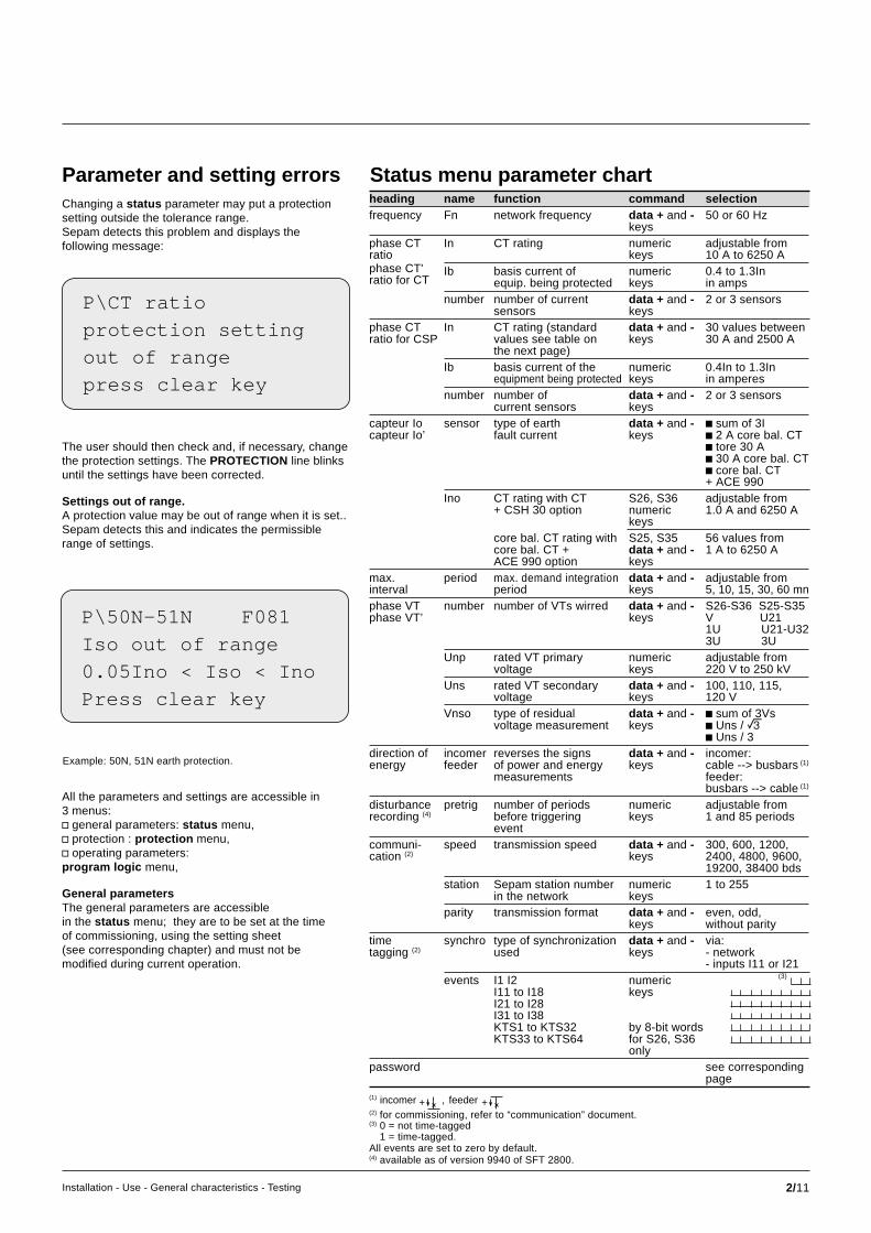
2/11Installation - Use - General characteristics - Testing
Parameter and setting errorsChanging a status parameter may put a protectionsetting outside the tolerance range.Sepam detects this problem and displays thefollowing message:
The user should then check and, if necessary, changethe protection settings. The PROTECTION line blinksuntil the settings have been corrected.
Settings out of range.A protection value may be out of range when it is set..Sepam detects this and indicates the permissiblerange of settings.
Status menu parameter chartheading name function command selectionfrequency Fn network frequency data + and - 50 or 60 Hz
keysphase CT In CT rating numeric adjustable fromratio keys 10 A to 6250 Aphase CT' Ib basis current of numeric 0.4 to 1.3Inratio for CT equip. being protected keys in amps
number number of current data + and - 2 or 3 sensorssensors keys
phase CT In CT rating (standard data + and - 30 values betweenratio for CSP values see table on keys 30 A and 2500 A
the next page)Ib basis current of the numeric 0.4In to 1.3In
equipment being protected keys in amperesnumber number of data + and - 2 or 3 sensors
current sensors keyscapteur Io sensor type of earth data + and - c sum of 3Icapteur Io’ fault current keys c 2 A core bal. CT
c tore 30 Ac 30 A core bal. CTc core bal. CT+ ACE 990
Ino CT rating with CT S26, S36 adjustable from+ CSH 30 option numeric 1.0 A and 6250 A
keyscore bal. CT rating with S25, S35 56 values fromcore bal. CT + data + and - 1 A to 6250 AACE 990 option keys
max. period max. demand integration data + and - adjustable frominterval period keys 5, 10, 15, 30, 60 mnphase VT number number of VTs wirred data + and - S26-S36 S25-S35phase VT’ keys V U21
1U U21-U323U 3U
Unp rated VT primary numeric adjustable fromvoltage keys 220 V to 250 kV
Uns rated VT secondary data + and - 100, 110, 115,voltage keys 120 V
Vnso type of residual data + and - c sum of 3Vsvoltage measurement keys c Uns / e
c Uns / 3direction of incomer reverses the signs data + and - incomer:energy feeder of power and energy keys cable --> busbars (1)
measurements feeder:busbars --> cable (1)
disturbance pretrig number of periods numeric adjustable fromrecording (4) before triggering keys 1 and 85 periods
eventcommuni- speed transmission speed data + and - 300, 600, 1200,cation (2) keys 2400, 4800, 9600,
19200, 38400 bdsstation Sepam station number numeric 1 to 255
in the network keysparity transmission format data + and - even, odd,
keys without paritytime synchro type of synchronization data + and - via:tagging (2) used keys - network
- inputs I11 or I21events I1 I2 numeric
I11 to I18 keysI21 to I28I31 to I38KTS1 to KTS32 by 8-bit wordsKTS33 to KTS64 for S26, S36
onlypassword see corresponding
page(1)
(2) for commissioning, refer to “communication” document.(3) 0 = not time-tagged
1 = time-tagged.All events are set to zero by default.(4) available as of version 9940 of SFT 2800.
P\CT ratio
protection setting
out of range
press clear key
P\50N-51N F081
Iso out of range
0.05Ino < Iso < Ino
Press clear key
Example: 50N, 51N earth protection.
All the parameters and settings are accessible in3 menus:v general parameters: status menu,v protection : protection menu,v operating parameters:program logic menu,
General parametersThe general parameters are accessiblein the status menu; they are to be set at the timeof commissioning, using the setting sheet(see corresponding chapter) and must not bemodified during current operation.
+ feederincomer +,
(3)

2/12 Installation - Use - General characteristics - Testing
Use - commissioningCommissioning (cont’d)
Microswitch SW1 and SW2settingsThe microswitch settings must be coherent with thechoices made in the status, phase CT ratioand VT ratio menus:
c current input for 1 A / 5 A CT1 A secondary 5 A secondary
SW2 SW2
ProtectionAccording to the type of Sepam 2000, the following functions are available:
Locked rotor / excessive starting time (48/51 LR)Protection of motors that are liable to start with overloads or insufficient supplyvoltage and/or drive loads that are liable to become locked (e.g. crusher). It is anovercurrent protection that is only confirmed after a time delay which correspondsto the normal start time.Recommendation: use short, definite time.
Negative sequence / unablance (46)Protection of equipment against overheating caused by an unbalanced powersupply, phase inversion or phase break, and against low levels of overcurrentbetween 2 phases.Recommendation: use IDMT curves.
Neutral unbalance (50/51)Detection of unbalance current between the neutral points of doublestar-connected capacitor banks; unbalance current indicates that componentsof one of the capacitors are damaged.
Rate of change of frequency (81R)Protection which calculates the rate of frequency variation and comparesit to a set point (used with uncoupling and load shedding).
Machine differential (87M-87G)Fast, sensitive protection of motors and generators against internal faultsdue to damaged insulation. The protection is based on the principle of percentagedifferentials, i.e. starting current restraint to sustain stability in spite of its high levelof sensitivity.
Thermal overload (49)Protetion of equipment against thermal damage caused by overloads. Thermaloverload is calculated according to a mathematical model, with 2 time constants,taking into account the effect of negative sequence current by means of anadjustable weighting coefficient:This function includes:v an adjustable setting to define equipment warm state (or alarm setting),v an adjustable tripping setting
Starts per hour (66)Protection against overheating caused by too frequent starts. Checking of:v number of starts per hour,v number of consecutive warm starts (detected by the thermal overloadprotection),v number of consecutive cold starts. The protection inhibits energizingfor a preset time period when the permissible limits are reached.
Tank frame leakage (50/51)Quick, selective detection of earth leakage current in transformer primary andsecondary windings. This overcurrent protection is associated with a currentsensor installed on the frame earthing connection. It calls for isolation of thetransformer tank.
Phase overcurrent (50/51)Three-phase connection and equipment protection against phase-to-phase faults.The following types of time delay settings are available: definite, standard inverse,very inverse, extremely inverse and ultra inverse.
Percentage type overcurrent (50/51 - 50N/51N)Detection of an unbalance current flowing between the two neutral pointsof double star mounted capacitor banks; this current indicates that the componentsof one of the banks are damaged.
Directional overcurrent (67)Incomer protection, which provides quick, selective protection against upstreamfaults when there are several power supplies in parallel.
c connection voltage inputv residual voltage measurement by sum
SW1
v residual current measurement by sum of 3 currents
SW1 SW1
v no residual voltage measurement
SW1
v residual current measurement by corebalance CT
SW1 SW1
v residual voltage measurement by broken delta-startransformer
SW1
c current input for CSP sensor
0 10 10 10 10 10 10 10 10 10 10 1
currentsensor rangeCSP
rated current of network
30-300 A 30 36 45 60 75 90 120 150 180 225 300
160-1600 A 160 192 240 320 400 480 640 800 960 1200 1600
500-2500 A 500 600 750 1000 1250 1500 2000 2500
SW2
v residual current measurement by sum of 3 currents
0 10 10 10 10 10 10 10 10 10 1 0 1SW1
Som1 Som2
v residual current measurement by core balance CT
SW10 1 0 1 0 1 0 1 0 1 0 1 0 1 0 1 0 1 0 1 0 1

2/13Installation - Use - General characteristics - Testing
Earth fault (50N/51N)Protection against earth faults. The following typesof time delay settings are available: definite, standardinverse, very inverse, extremely inverse and ultrainverse.Earth fault current detection can be provided by:v three phase current transformers,v a current transformer (1 A, 5 A), combined witha CSH30 interposing ring CT,v a CSH120 or CSH200 core balance CT, accordingto the required diameter, this method being the mostaccurate one.The two ratings available (2 A and 30 A) providea very wide setting range,
Directional earth fault (67N)This protection has several uses:v highly sensitive earth fault protection of transformerfeeders supplied by long cables characterized by highcapacitive current,v quick, selective detection of upstream earth faultswhen there are several incomers in parallel.
Overvoltage (59)Protection against abnormally high voltage andchecking that there is sufficient voltage of powersupply changeover. This protection monitors systemvoltage U21.
Neutral voltage displacement (59N)Detection of insulation faults in ungrounded systemsby measurement of neutral voltage displacement.This protection is generally used for transformerincomers or busbars.
Undercurrent (37)Pump protection against the consequences of primingloss. This protection detects delayed undercurrentcorresponding to motor no-load operation which istypical of a loss of pump priming.
Underfrequency (81L)Detection of variances with respect to the rated frequency, in order to maintainhigh quality power supply. This protection can be used for overall tripping or forload shedding.
Overfrequency (81H)Protection against abnormally high frequency.
Undervoltage (27)Protection used either for automated functions (changeover, load shedding)or for the protection of several motors against undervoltage. This protection checksfor undervoltage in each of the phase-to-phase voltages measured.
Positive sequence undervoltage (27D)Protection of several motors against malfunctioning due to insufficientor unbalanced supply voltage.
Remanent undervoltage (27R)Monitoring of the clearing of voltage sustained by rotating machines after theopening of the circuit. This protection is used with automatic changeover functionsto prevent transient electrical and mechanical phenomena that are caused by fastresupply of power to motors. It monitors system voltage U21.
Neutral (50N/51N)Overload protection of neutral earthing impedance and sensitive overall networkprotection against earth faults. This “earth fault” protection is associated witha current sensor installed on the neutral earthing connection.
Reactive overpower (32Q/40)Protection of synchronous drives against field loss which causes overconsumptionof reactive power and leads to the loss of synchronism.
Reverse real power (32P)Protection of motors against operation as generators when driven by their loads or,in the case of double sources, to avoid the output of one source into the other.It is based on the real overpower function F531.
Direction of rotation (47)Protection which prevents the changing of direction of motor rotation followinga power supply modification.
Temperature monitoring (38/49T)Protection which detects abnormal overheating of equipment fittedwith Pt100 type platinum resistor type temperature sensors.v 1 alarm setting,v 1 tripping setting.The cabling of each sensor is continuously monitored.
Voltage restrained overcurrent (51V)Three-phase protection against alternator phase faults. Its characteristics aresuitable for the weak current suppied by the alternator when a short-circuit occurs.
Synchro-check (25)Closing of the breaking device if the two circuits have voltage, frequency or phasevariances within the planned limits.
Restricted earth fault (64 REF)Detection of phase to earth faults in the winding of the transformer connected tothe secondary end of the protection. This protection may be used when thesecondary neutral is earthed inside the protected zone.

2/14 Installation - Use - General characteristics - Testing
Use - commissioningCommissioning (cont’d)
display function ANSI pocket parameters commands setting limitsmessages terminal
item
LOCK. ROTOR 48/51LR F441 Is setting numeric keys 0.5 to 5IbLONG START and units
ST long start numeric keys 0.5 s to 655 stime delay and units
LT locked rotor numeric keys 0.05 s to 655 stime delay and units
UNBALANCE 46 F451 curve choice of data + and - keys DT or IDMTtripping curve
Is setting numeric keys DT: 0.1 to 5Iband units IDMT: 0.1 to 0.5Ib
T time delay numeric keys DT: 0.1 to 655 sand units IDMT: 0.1 to 1s at 5Ib
LOAD SHED 27D F381 Vsd setting numeric keys 0.3 Vnp to Vnpand units
F382 T time delay numeric keys 0.05 s to 655 sand units
ROTATION direction of 47 Vd rotation direction metering (Vnp = Unp/V3)rotation fault
LOM1 rate of change 81R F581 dFs/dt setting numeric keys 0.1 to 10 Hz/sof frequency and units
LOM2 F582 T time delay numeric keys 0.1 to 655 sand units
MOTOR DIFF. machine 87M F621 Is setting numeric keys 0.05 In to 0.5 Indifferential and units (min.: 1A)
GEN. DIFF. 87G
FIELD LOSS reactive 32Q/40 F541 Qs setting numeric keys O.05 to 1.2 Snoverpower and units
T time delay numeric keys 0.1 s to 655 sand units
FRAME LEAK frame leak 50/51 F021 curve choice of data + and - keys DT, SIT, VIT, EIT, UITtripping curve
Is setting numeric keys DT: 0.3 to 24 Inand units SIT, VIT, EIT, UIT:
0.3 to 2.4 In
T time delay numeric keys DT: 0.05 to 655 sand units SIT, VIT, EIT, UIT, LIT:
0.1 to 12.5 s at 10 Is
OVERCURRENT phase 50/51 F011 to curve choice of data + and - keys DT, SIT, VIT, EIT, UITor HIGH O/C overcurrent F014 tripping curve
Is setting numeric keys DT : 0,3 to 24 Inand units SIT, VIT, EIT, UIT :
0.3 to 2.4 In
T time delay numeric keys DT : 0.05 to 655 sand units SIT, VIT, EIT, UIT :
0.1 to 12.5 s at 10 Is
O/C V REST voltage restrained 50/51V F191 curve choice of data + and - keys DT, SIT, VIT, EIT, UITovercurrent tripping curve
Is setting numeric keys DT: 0.3 to 24 Inand units SIT, VIT, EIT,UIT:
0.3 to 2.4 In
T time delay numeric keys DT: 0.05 to 655 sand units SIT, VIT, EIT, UIT:
0.1 to 12.5 s at 10 Is
Protection function setting ranges
DT: definite timeSIT, VIT, EIT, UIT: IDMT (inverse)
UNDERVOLT.1UNDERVOLT.2
locked rotor /excessive startingtime
negativesequence /unbalance
positivesequenceundervoltage
LOW O/C

2/15Installation - Use - General characteristics - Testing
display function ansi pocket parameters commands setting limitsmessages terminal
item
DIR. O/C directional 67 F511* curve choice of data + and - keys DT, SIT, VIT, EIT,UITovercurrent F521 tripping curve
Is setting numeric keys DT: 0.3 to 24Inand units SIT, VIT, EIT, UIT:
0.3 to 2.4In
T time delay numeric keys DT: 0.05 to 655 sand units SIT, VIT, EIT, UIT:
0.1 to 12.5 s at 10 Is
angle characteristic data + and - keys 30°, 45° or 60°angle
Phi1 phase shift metring between I1 and U32Phi2 between I2 and U13Phi3 between I3 and U21
EARTH FAULT earth fault 50N/51N curve choice of data + and - keys DT, SIT, VIT, EIT, UIT50G/51G tripping curve
Iso setting numeric keys DT with:and units Sum3I: 0.05 to 10In
CT+CSH 30: 0.05 to 10InoCSH 2A: 0.1 to 20 ACSH 30A: 1.5 A to 300 ACore bal. CT+ ACE 990:0.05 to 10 InoSIT, VIT, EIT, UIT with:Sum3I: 0.05 to InCSH 30: 0.05 to 10InoCSH 2A: 0.1 to 2 ACSH 30A: 1.5 A to 300 ACore bal. CT + ACE 990:0.05 to Ino
T time delay numeric keys DT: 50 ms to 655 sand units SIT, VIT, EIT, UIT:
0.1 to 12.5 s at 10 Iso
DIR. E/F directional 67N F501 Iso setting numeric keys Sum3I: 0.05 to 10Inearth fault and units CSH 30: 0.05 to 10Ino
CSH 2A: 0.1 to 20 ACSH 30A: 1.5 A to 300 ACore bal. CT + ACE 990:0.05 to 10 Ino
T time delay numeric keys 0.05 to 655 sand units
angle characteristic data + and - keys 0°, 15°, 30°, 45°, 60°,angle 90°, -45°
Phi0 phase shift metering between Io and Vo
neutral 50N/51N F091 curve choice of data + and - keys DT, SIT, VIT, EIT, UITunbalance F092 tripping curve
F071 Iso setting numeric keys DT with:F072 and units Sum3I: 0.05 to 10In
CT+CSH 30: 0.05 to 10 InoCSH 2A : 0.1 to 20 ACSH 30A:1.5 A to 300 ACore bal. CT + ACE 990:0.05 to 10 InoSIT, VIT, EIT, UIT, with:Sum3I: 0.05 to InCT+CSH 30:1.5 A to 300 ACore bal. CT + ACE 990:0.05 to InoCSH 2A: 0.1 to 2 ACSH 30A: 1.5 to 30 A
T time delay numeric keys DT: 50 ms to 655 sand units SIT, VIT, EIT, UIT:
0.1 to 12.5 s at 10 IsoRET** H2 restraint data + and - keys yes / no
OVERFREQ. 1 overfrequency 81H F571 Fs setting numeric keys for 50 Hz: 50 to 55 HzOVERFREQ. 2 F572 and units for 60 Hz: 60 to 65 Hz
T time delay numeric keys 0.1 to 655 sand units
F061 toF064F081 toF084
* for Sepam 2000 S25 and S35.** for F081 to F084 and F091, F092 only.
NEUTR. O/C1NEUTR. O/C2or E/F IO’
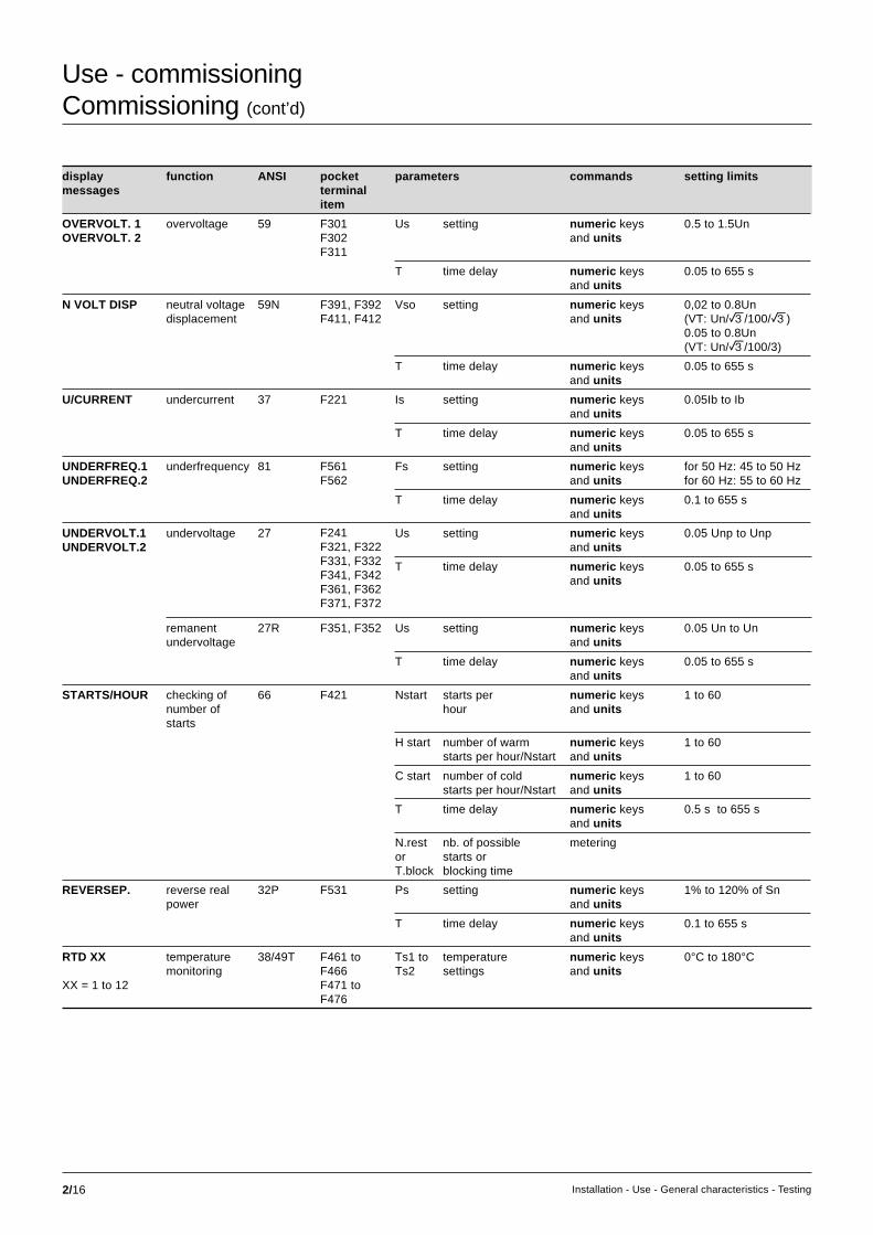
2/16 Installation - Use - General characteristics - Testing
Use - commissioningCommissioning (cont’d)
display function ANSI pocket parameters commands setting limitsmessages terminal
item
OVERVOLT. 1 overvoltage 59 F301 Us setting numeric keys 0.5 to 1.5UnOVERVOLT. 2 F302 and units
F311
T time delay numeric keys 0.05 to 655 sand units
N VOLT DISP neutral voltage 59N F391, F392 Vso setting numeric keys 0,02 to 0.8Undisplacement F411, F412 and units (VT: Un/e/100/e)
0.05 to 0.8Un(VT: Un/e/100/3)
T time delay numeric keys 0.05 to 655 sand units
U/CURRENT undercurrent 37 F221 Is setting numeric keys 0.05Ib to Iband units
T time delay numeric keys 0.05 to 655 sand units
UNDERFREQ.1 underfrequency 81 F561 Fs setting numeric keys for 50 Hz: 45 to 50 HzUNDERFREQ.2 F562 and units for 60 Hz: 55 to 60 Hz
T time delay numeric keys 0.1 to 655 sand units
UNDERVOLT.1 undervoltage 27 Us setting numeric keys 0.05 Unp to UnpUNDERVOLT.2 and units
T time delay numeric keys 0.05 to 655 sand units
remanent 27R F351, F352 Us setting numeric keys 0.05 Un to Unundervoltage and units
T time delay numeric keys 0.05 to 655 sand units
STARTS/HOUR checking of 66 F421 Nstart starts per numeric keys 1 to 60number of hour and unitsstarts
H start number of warm numeric keys 1 to 60starts per hour/Nstart and units
C start number of cold numeric keys 1 to 60starts per hour/Nstart and units
T time delay numeric keys 0.5 s to 655 sand units
N.rest nb. of possible meteringor starts orT.block blocking time
REVERSEP. reverse real 32P F531 Ps setting numeric keys 1% to 120% of Snpower and units
T time delay numeric keys 0.1 to 655 sand units
RTD XX temperature 38/49T F461 to Ts1 to temperature numeric keys 0°C to 180°Cmonitoring F466 Ts2 settings and units
XX = 1 to 12 F471 toF476
F241F321, F322F331, F332F341, F342F361, F362F371, F372

2/17Installation - Use - General characteristics - Testing
display function ANSI pocket parameters commands setting limitsmessages terminal
item
THERMAL thermal overload 49 F431 OL1 alarm setting numeric keys 50% to 200%(or hot state) and units
OL2 tripping numeric keys 50% to 200%setting and units
Adjust unbalance data + and - keys without = 0, low = 2.25factor average = 4.5, high = 9
T1 heat rise numeric keys 5 to 120 mntime constant and units
T2 cooling numeric keys 5 to 600 mntime constant and units
Heating heat rise metering
SYN CHECK synchronism 25 F171 dUs voltage variance numeric keys 0.03 to 0.3Uncheck F181 setting and units
dFs frequency variancenumeric keys 0.05 to 0.5 Hzsetting and units
dPhi phase variance numeric keys 5 to 45 degreessetting and units
Us high setting numeric keys 0.8 to 1.1 Unand units
Us low setting numeric keys 0.1 to 0.7 Unand units
mode operating data + and - keys mode 1 to 4mode
dPhi phase shift meteringvalue
Usync1 voltage meteringand Usync2 values
REF restricted 64REF F641 Iso setting numeric keys 0.05 to 0.8 Inearth fault F651 and units
F661
BREAKER protection 50BF-62 F981 Is setting numeric keys 0.2 to 2 InFAILURE against and units
circuit breaker T1 faulty CB numeric keys 0.05 to 65.5 sfailures retripping and units
time delay
T2 adjacent CB numeric keys 0.05 to 65.5 sretripping and unitstime delay
3-ph I, assignment data + and - keys Ioo-I1-I2phase 1 I, of logic inputs I11 to I18phase 2 I, to trip data I21 to I28 (1)
phase 3 I. I31 to I38 (1)
UNBAL.ALx 50/51 Is setting numeric keys 3 to 200% In,UNBAL.TRIPx and units
T time delay numeric keys 0.05 to 655 svalue and units
x = capacitornumber
(1) according to the number of ESTOR logic input/output boards.Refer to the document entitled "testing", ref. 3140746, regarding protection testing.For further information on the protection function characteristics, .refer to the document entitled “Metering and protection functions”, ref. 3140747.
percentagetypeovercurrent
F111F112F121F122F131F132
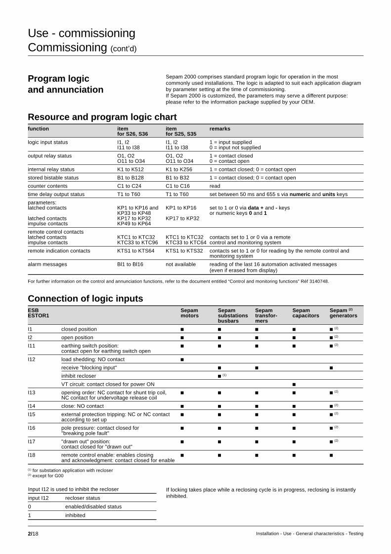
2/18 Installation - Use - General characteristics - Testing
Use - commissioningCommissioning (cont’d)
Program logicand annunciation
Sepam 2000 comprises standard program logic for operation in the mostcommonly used installations. The logic is adapted to suit each application diagramby parameter setting at the time of commissioning.If Sepam 2000 is customized, the parameters may serve a different purpose:please refer to the information package supplied by your OEM.
Resource and program logic chartfunction item item remarks
for S26, S36 for S25, S35
logic input status I1, I2 I1, I2 1 = input suppliedI11 to I38 I11 to I38 0 = input not supplied
output relay status O1, O2 O1, O2 1 = contact closedO11 to O34 O11 to O34 0 = contact open
internal relay status K1 to K512 K1 to K256 1 = contact closed; 0 = contact open
stored bistable status B1 to B128 B1 to B32 1 = contact closed; 0 = contact open
counter contents C1 to C24 C1 to C16 read
time delay output status T1 to T60 T1 to T60 set between 50 ms and 655 s via numeric and units keys
parameters:latched contacts KP1 to KP16 and KP1 to KP16 set to 1 or 0 via data + and - keys
KP33 to KP48 or numeric keys 0 and 1latched contacts KP17 to KP32 KP17 to KP32impulse contacts KP49 to KP64
remote control contactslatched contacts KTC1 to KTC32 KTC1 to KTC32 contacts set to 1 or 0 via a remoteimpulse contacts KTC33 to KTC96 KTC33 to KTC64 control and monitoring system
remote indication contacts KTS1 to KTS64 KTS1 to KTS32 contacts set to 1 or 0 for reading by the remote control andmonitoring system
alarm messages Bl1 to Bl16 not available reading of the last 16 automation activated messages(even if erased from display)
Connection of logic inputsESB Sepam Sepam Sepam Sepam Sepam (2)
ESTOR1 motors substations transfor- capacitors generatorsbusbars mers
I1 closed position c c c c c (2)
I2 open position c c c c c (2)
I11 earthing switch position: c c c c c (2)
contact open for earthing switch open
I12 load shedding: NO contact creceive "blocking input" c c cinhibit recloser c (1)
VT circuit: contact closed for power ON cI13 opening order: NC contact for shunt trip coil, c c c c c (2)
NC contact for undervoltage release coil
I14 close: NO contact c c c c c (2)
I15 external protection tripping: NC or NC contact c c c c c (2)
according to set up
I16 pole pressure: contact closed for c c c c c (2)
"breaking pole fault"
I17 "drawn out" position: c c c c c (2)
contact closed for "drawn out"
I18 remote control enable: enables closing c c c c cand acknowledgment: contact closed for enable
(1) for substation application with recloser(2) except for G00
input I12 recloser status
0 enabled/disabled status
1 inhibited
Input I12 is used to inhibit the recloser If locking takes place while a reclosing cycle is in progress, reclosing is instantlyinhibited.
For further information on the control and annunciation functions, refer to the document entitled “Control and monitoring functions” Réf 3140748.

2/19Installation - Use - General characteristics - Testing
ESTOR2 Sepam Sepam Sepam Sepamsubstations transformers capacitors generatorsbusbars
I21 reserved for external synchronization c c c cof communication
I22 auxiliary voltage on, PTC sensors c c (3)
emergency stop (NC contact) c (1)
busbar VT circuit 1 c (2)
(contact closed for power on)
I23 DGP: gas, level c c (3)
external generator shutdown control c (1)
capacitor 1 switch opencontact closed when switch open (C/O)
I24 DGP: pressure c c (3)
coupling enabled (closed for enabled) c (1)
capacitor 1 switch closed ccontact closed when switch closed (O/O)
I25 thermostat: alarm c c (3)
external de-energizing control c (1)
capacitor 1 switch open ccontact closed when switch closed (C/O)
I26 thermostat: tripping c c (3)
busbar VT circuit c (5)
transformer failure (alarm) c (4)
capacitor 2 switch closed ccontact closed when switch closed (O/O)
I27 Buchholz: alarm c c (3)
generator VT circuit c (5)
transformer failure (tripping) c (4)
capacitor 3 switch open ccontact closed when switch closed (C/O)
I28 Buchholz: tripping c c (3)
capacitor 3 switch closed ccontact closed when switch closed (O/O)
PTC sensor auxiliary voltage present c (4)
(1) except for G00(2) for B07(3) for G00(4) for G15, G16(5) for G03, G04
ESTOR3 Sepam Sepam Sepam Sepam (2)
substations transformers capacitors generatorsbusbars motors
I31 busbar VT circuit 2 c (2)
(contact closed for power on)
external disabling of capacitor control cI34 manual capacitor control cI35 automatic capacitor control cI36 varmeter control of capacitor 1 switch, c
contact closed for closing
I37 varmeter control of capacitor 2 switch, ccontact closed for closing
I38 varmeter control of capacitor 3 switch, ccontact closed for closing

2/20 Installation - Use - General characteristics - Testing
Use - commissioningCommissioning (cont’d)
ESB Sepam Sepam Sepam Sepam Sepam (2)
ESTOR1 motors substations transfor- capacitors generatorsbusbars mers
O1 open: NO or NC contact c c c c c (2)
according to set up
overcurrent or c (7)
directional overcurrent
O2 close: NO contact c c c c c (2)
neutral or directional earth fault c (7)
or restricted earth fault
O11 RTD alarm or RTD fault c c (2)
neutral voltage displacement creverse real power c c (7)
neutral unbalance alarm, thermal overeload ccycle in progress c (1)
reverse real power c (5)
O12 fault tripping indication c c c c c (2)
field loss (reverse reactive power) c (7)
O13 device fault c c c c c (2)
(pressure fault or control fault)
neutral voltage displacement c (7)
O14 transmit "blocking input" c c c c c (7)
de-energizing c (2)
ESTOR2 Sepam Sepam Sepam Sepam Sepam (2)
motors substations transfor- capacitors generatorsbusbars mers
O21 positive sequence undervoltage c (9)
undervoltage c (6) c c (10)
underfrequency c (10)
undervoltage, or underfrequency busbars 1 c (4)
closing order capacitor 1 switch cO22 remanent undervoltage c (3)(3) c
overvoltage, or overfrequency c (10)
undervoltage busbars 2 c (4)
closing order capacitor 1 switch cO23 underfrequency c (9)(11)
intertripping cneutral voltage displacement c (2)
underfrequency or alarm: c (7)
thermal overload, Buchholz,thermostat, gas detector, PTC sensors
remanent undervoltage busbars 1 c (4)
O24 overfrequency c (8)(9)(11)
overvoltage c (3) cgenerator shutdown c (2)
overvoltage or tripping: c (7)
thermal overload, Buchholz,thermostat, gas detector, PTC sensors
minimum de tension rémanente barres 2 c (4)
capacitor switch fault c(7) for G00(8) for B12(9) for B02(10) except for G01, GO2, G12(11) for S07, S08
(1) substation applications with recloser(2) except for G00(3) except for B07(4) for B07(5) for S09(6) except for S09
Connection of logic outputs

2/21Installation - Use - General characteristics - Testing
ESTOR3 Sepam Sepam Sepam Sepam (1)
substations transfor- capacitors generatorsbusbars mers motors
O31 closing order capacitor 2 switch covervoltage, or overfrequency busbars 1 c (2)
underfrequency setting x / rate of change of frequency setting x c (3)
O32 opening order capacitor 2 switch covervoltage busbars 2 c (2)
underfrequency setting x / rate of change of frequency setting x c (3)
O33 closing order capacitor 3 switch csynchronization c (2)
underfrequency setting x / rate of change of frequency setting x c (3)
O34 opening order capacitor 3 switch cunderfrequency setting x / rate of change of frequency setting x c (3)
(1) except for G00(2) for B07(3) for B12

2/22 Installation - Use - General characteristics - Testing
time delays functiontrip circuit or open / closed matching supervision
T1 = 2 s (2) time delay for recovery of open/closed information upon changes in device positionopen / close control
T2 = 0.2 s contactor diagram: tripping order durationlogic discrimination
T3 = 0.2 s inhibition of blocking input transmission after trippingopen / close control by telecommunication
T5 = 0.2 s duration of tripping order pulse transmitted via remote controlT6 = 0.2 s duration of closing order pulse transmitted via remote control
(T6 is also used by the restart function)T16 = 0.2 s confirmation of pressure switch fault
Sepam 2000 : motorT4 load shedding: external load shedding order time delay (input I12)T6 = 0.2 s restart: duration of closing order pulse transmitted via a restart orderT8 restart: maximum duration of voltage sag enabling restartT9 restart: restart staggering time delay
Sepam 2000 : capacitorT7 after tripping, duration of reclosing inhibition
(allows correct discharging of capacitors prior to re-energizing)T21 capacitor 1 opening time delay
(allows staggered opening of capacitor switches)T22 capacitor 2 opening time delay
(allows staggered opening of capacitor switches)T23 capacitor 3 opening time delay
(allows staggered opening of capacitor switches)T24 circuit breaker opening time delay
(the breaker only opens after the straggered opening of the capacitors)T25 duration of capacitor 1 tripping pulseT26 duration of capacitor 2 tripping pulseT27 duration of capacitor 3 tripping pulseT28 duration of capacitor 1 closing pulseT29 duration of capacitor 2 closing pulseT30 duration of capacitor 3 closing pulseT31 after tripping, duration of capacitor 1 inhibitionT32 after tripping, duration of capacitor 2 inhibitionT33 after tripping, duration of capacitor 3 inhibitionT34 time delay for recovery of capacitor 1 switch open/closed informationT35 time delay for recovery of capacitor 2 switch open/closed informationT36 time delay for recovery of capacitor 3 switch open/closed information
Sepam 2000 : busbarsT7 = 10 s time during which instantaneous dF/dt data is maintained
when load shedding with underfrequency only is chosen (KP33 = 1)T8 maintain output O32 for synchro-check
(set the time delay to several secondes if the output is not used)T10 maintain closing request for synchro-checkT24 duration of load shedding pulses on O31T25 duration of load shedding pulses on O32T26 duration of load shedding pulses on O33T27 duration of load shedding pulses on O34
Sepam 2000 : substationT4 = 1 s time delay after closing (used to display transient phenomena)T25 = 0.2 s duration of tripping pulseT26 = 0.2 s duration of closing pulseT10 recloser function: disengaging time delayT11 recloser function: isolation time delay linked to cycle 1T12 recloser function: isolation time delay linked to cycle 2T13 recloser function: isolation time delay linked to cycle 3T14 recloser function: isolation time delay linked to cycle 4T15 recloser function: inhibition time delay
Sepam 2000 : generatorT10 maintain closing request for synchro-check
Time delay settings
Use - commissioningCommissioning (cont’d)
The time delays are factory-set by default to 200 ms.In the chart below, if the function is not used, setting of the related time delaysis unnecessary.
(1) This time delay may be increased to mask switching problems.

2/23Installation - Use - General characteristics - Testing
functions parameters
open / close control KP1 KP2
circuit breaker with shunt-trip coil 0 0
circuit breaker with undervoltage release coil 1 0
latching contactor with tripping by shunt-trip coil 0 1
external protection logic inputs
input I15, external protection tripping normally open contact KP4 = 0
normally closed contact KP4 = 1
recloser: enable / disable
with Sepam in local mode (input I18 = 0) disabled KP6 = 0
enabled KP6 = 1
recloser: recloser cycle set up
reclosing cycle 1 inactive KP7 = 0
active KP7 = 1
reclosing cycle 2 inactive KP8 = 0
active KP8 = 1
reclosing cycle 3 inactive KP9 = 0
active KP9 = 1
reclosing cycle 4 inactive KP10 = 0
active KP10 = 1
recloser: tripping set up
tripping linked to cycle 1 time-delayed KP11 = 0
instantaneous KP11 = 1
tripping linked to cycle 2 time-delayed KP12 = 0
instantaneous KP12 = 1
tripping linked to cycle 3 time-delayed KP13 = 0
instantaneous KP13 = 1
tripping linked to cycle 4 time-delayed KP14 = 0
instantaneous KP14 = 1
definitive tripping time-delayed KP15 = 0
instantaneous KP15 = 1
counters
reset to zero of operation counter KP19 = 1
reset to zero of phase fault trip counter KP20 = 1
reverse real power (Sepam 2000, S09 type)
reverse real power with tripping KP36 = 1
reverse real power with annunciation KP36 = 0
remote setting
remote setting enable KP38 = 0
remote setting disable KP38 = 1
disturbance recording
inhibition KP50 = 1
automatic triggering KP51 = 1
manual triggering KP52 = 1
other
display of program logic set up KP17 = 1
BI (blocking input) pilot wire test KP18 = 1
Sepam 2000: substation
Set up The parameters may be set using:c TSM 2001 pocket terminal,c SFT 2801 or SFT 2821 software.

2/24 Installation - Use - General characteristics - Testing
Use - commissioningCommissioning (cont’d)
Sepam 2000: busbars
functions parametersopen / close control KP1 KP2circuit breaker with shunt-trip coil 0 0circuit breaker with undervoltage release coil 1 0atching contactor with tripping by shunt-trip coil 0 1external protection logic inputsinput I15, external protection tripping normally open contact KP4 = 0
normally closed contact KP4 = 1countersreset to zero of operation counter KP19 = 1reset to zero of phase fault trip counter KP20 = 1type of load shedding (Sepam 2000, B12 type)underfrequency or dF/dt KP33 = 0underfrequency AND NOT dF/dt KP33 = 1synchro-check (Sepam 2000, B07 type)acknowledgment of operating mode with power off KP35 = 1no acknowledgment of operating mode with power off KP35 = 0remote settingremote setting enable KP38 = 0remote setting disable KP38 = 1disturbance recordinginhibition KP50 = 1automatic triggering KP51 = 1manual triggering KP52 = 1otherdisplay of program logic set up KP17 = 1BI (blocking input) pilot wire test KP18 = 1
The parameters are set using the TSM 2001 pocket terminal.
Sepam 2000: SX
functions parametersopen / close control KP1 KP2circuit breaker with shunt-trip coil 0 0circuit breaker with undervoltage release coil 1 0latching contactor with tripping by shunt-trip coil 0 1inputsI1 = close, I2 = open KP3 = 0I1 = close, I2 = receive blocking input KP3 = 1outputsO1 = open, O2 = close KP4 = 0O1 = open, O2 = send blocking input KP4 = 1countersreset to zero of operation counter KP19 = 1reset to zero of phase fault trip counter KP20 = 1remote settingremote setting enable KP38 = 0remote setting disable KP38 = 1disturbance recordinginhibition KP50 = 1automatic triggering KP51 = 1manual triggering KP52 = 1otherdisplay of program logic set up KP17 = 1BI (blocking input) pilot wire test KP18 = 1

2/25Installation - Use - General characteristics - Testing
Sepam 2000: transformers
functions parameters
open / close control KP1 KP2
circuit breaker with shunt-trip coil 0 0
circuit breaker with undervoltage release coil 1 0
latching contactor with tripping by shunt-trip coil 0 1
external protection logic input
input I15, external protection tripping normally open contact KP4 = 0
normally closed contact KP4 = 1
Buchholz / thermostat / DGPT / external protection logic inputs
inputs I23 to I28 excited, normally open contact KP5 = 0
if fault detection by Buchholz / thermostat / DGPT normally closed contact KP5 = 1
input I23, detection of gas or drop in level tripping KP6 = 0
alarm KP6 = 1
protection
tank frame leakage KP7 = 0
restricted earth fault KP7 = 1
counters
reset to zero of operation counter KP19 = 1
reset to zero of phase fault trip counter KP20 = 1
remote setting
remote setting enable KP38 = 0
remote setting disable KP38 = 1
disturbance recording
inhibition KP50 = 1
automatic triggering KP51 = 1
manual triggering KP52 = 1
other
display of program logic set up KP17 = 1
BI (blocking input) pilot wire test KP18 = 1

2/26 Installation - Use - General characteristics - Testing
Sepam 2000: generators (except for G00 type)
functions parameters
open / close control KP1 KP2
circuit breaker with shunt-trip coil 0 0
circuit breaker with undervoltage release coil 1 0
latching contactor with tripping by shunt-trip coil 0 1
contactor with impulse control 1 1
transformer monitoring (Sepam 2000, G15 and G16 types)
transformer sensors normally closed contact KP4 = 0
normally open contact KP4 = 1
counters
rest to zero of operation counter KP19 = 1
reset to zero of phase fault trip counter KP20 = 1
reset to zero of running hours counter KP21 = 1
other
tripping undervoltage, setting 1 KP5 = 1
undervoltage, setting 2 KP6 = 1
overvoltage, setting 1 KP7 = 1
overvoltage, setting 2 KP8 = 1
neutral voltage displacement KP9 = 1
underfrequency KP10 = 1
overfrequency KP11 = 1
latching undervoltage, setting 1 KP13 = 1
undervoltage, setting 2 KP14 = 1
overvoltage, setting 1 KP15 = 1
overvoltage, setting 2 KP16 = 1
de-energizing overvoltage, setting 1 KP7 = 1
overvoltage, setting 2 KP8 = 1
shutdown reverse real power KP12 = 1
display of set up control scheme KP17 = 1
BI (blocking input) pilot wire test KP18 = 1
remote setting
remote setting enable KP38 = 0
remote setting disable KP38 = 1
disturbance recording
inhibition KP50 = 1
automatic triggering KP51 = 1
manual triggering KP52 = 1
synchro-check (Sepam 2000, G03 and G04 types)
with synchro-check KP34 = 0
no synchro-check KP34 = 1
acknowledgment of operating mode with power off KP35 = 1
no acknowledgment of operating mode with power off KP35 = 0
transformer monitoring (Sepam 2000, G15 and G16 types)
transformer sensors normally closed contact KP35 = 0
normally open contact KP35 = 1
use of Sepam 2000, G01, G02 and G12 types with G00 (generator-transformer units)
disabling of reverse real and reactive power protections KP33 = 1
Use - commissioningCommissioning (cont’d)

2/27Installation - Use - General characteristics - Testing
Sepam 2000: generators, G00 type
functions parametersBuchholz / thermostat / DGPT logic inputstransformer sensors normally closed contact KP5 = 0
normally open contact KP5 = 1
input I23, detection of gas or drop in level tripping KP6 = 0
alarm KP6 = 1
latchingunderfrequency KP10 = 1
undervoltage, setting 1 KP13 = 1
undervoltage, setting 2 KP14 = 1
overvoltage, setting 1 KP15 = 1
overvoltage, setting 2 KP16 = 1
assignment of inputs / outputsoutputs O21 to O24 without transformer failure O21 undervoltage KP33 = 0
O22 overfrequencyO23 underfrequencyO24 overvoltage
outputs O21 to O24 with transformer failure O21 undervoltage OR underfrequency KP33 = 1O22 overfrequency OR overfrequencyO23 Buchholz / thermostat / DGPT with alarmO24 Buchholz / thermostat / DGPT with tripping
input I18: remote control enable enable if I18 = 1 KP34 = 1
(acknowledgment, remote setting) enable regardless of position of I18 KP34 = 0
remote settingremote setting enable KP38 = 0
remote setting disable KP38 = 1
disturbance recordinginhibition KP50 = 1
automatic triggering KP51 = 1
manual triggering KP52 = 1
Sepam 2000: motors
functions parameters
open / close control KP1 KP2 KP3
circuit breaker with shunt-trip coil 0 0 0
circuit breaker with undervoltage release coil 1 0 0
latching contactor with tripping by shunt-trip coil 0 1 0
contactor with impulse control 1 1 0
contactor with latched control 1 1 1
transformer monitoring
transformer sensors normally closed contact KP4 = 0
normally open contact KP4 = 1
counters
reset to zero of operation counter KP19 = 1
reset to zero of phase fault trip counter KP20 = 1
reset to zero of running hours counter KP21 = 1
remote setting
remote setting enable KP38 = 0
remote setting disable KP38 = 1
disturbance recording
inhibition KP50 = 1
automatic triggering KP51 = 1
manual triggering KP52 = 1
other
display of program logic set up KP17 = 1
BI (blocking input) pilot wire test KP18 = 1

2/28 Installation - Use - General characteristics - Testing
Use - commissioningCommissioning (cont’d)
Set up: capacitors
functions parameters
open / close control KP1 KP2
circuit breaker with shunt-trip coil 0 0
circuit breaker with undervoltage release coil 1 0
latching contactor with tripping by shunt-trip coil 0 1
transformer monitoring
transformer sensors normally closed contact KP4 = 0
normally open contact KP4 = 1
counters
reset to zero of operation counter KP19 = 1
reset to zero of phase fault trip counter KP20 = 1
reset to zero of running hours counters KP21 = 1
choice of number of capacitors KP36 KP37
3 capacitors 0 0
2 capacitors 0 1
1 capacitor 1 1
remote setting
remote setting enable KP38 = 0
remote setting disable KP38 = 1
disturbance recording
inhibition KP50 = 1
automatic triggering KP51 = 1
manual triggering KP52 = 1
switch open / close control
capacitor 1 switch closing KP54 = 1
capacitor 1 switch opening KP55 = 1
capacitor 2 switch closing KP56 = 1
capacitor 2 switch opening KP57 = 1
capacitor 3 switch closing KP58 = 1
capacitor 3 switch opening KP59 = 1
capacitor control
manual control KP60 = 1
automatic control KP61 = 1
other
display of program logic set up KP17 = 1
BI (blocking input) pilot wire test KP18 = 1

2/29Installation - Use - General characteristics - Testing
The parameters in the chart below serve as operating assistance.
They do not correspond to control and monitoring function parameter settings.
They automatically switch back to zero 30 seconds after they are set to 1.
parameter function
open / close control
KP17 = 1 display of program logic set up: display messagecircuit breaker with shunt-trip coil SHUNT-TRIPcircuit breaker with undervoltage release coil U/V RELEASElatching contactor LATCH CTRLcontactor with impulse orders IMP. CTRLcontactor with latched orders PERM. CTRL
logic discrimination
KP18 = 1 pilot wire testing: KP18 active if output O14 set to send blocking inputSepam units which receive the blocking input display the message RECEIVE BI.This contact facilitates pilot wire testing.
counters
KP19 = 1 reset to zero of operation counter (C1)
KP20 = 1 reset to zero of phase fault trip counter (C2)and earth fault trip counter (C3 for substation Sepam)
KP21 = 1 motor and generator Sepam: reset to zero of running hours counter (C3)capacitor Sepam: reset to zero of running hours counters (C4, C5, C6)
KP22 = 1 substation Sepam: reset to zero of specific recloser counters (C4 to C8)

2/30 Installation - Use - General characteristics - Testing
functions commands outputs annunciation
trip O1 inhibit lockout transmit O11 O21 O22 O23 O24 fault trip device message (1)
closing BI O14 O12 faultO13
phase c c (2) c (2) c c OVERCURRENTovercurrent
earth fault c c (2) c (2) c c E/F
undervoltage c UNDERVOLT.1setting 1
undervoltage c UNDERVOLT.2setting 2
pos. seq. undervoltage, c P SEQ U/V1setting 1
pos. seq. undervoltage, c P SEQ U/V2setting 2
remanent cundervoltage
overvoltage c OVERVOLT.1setting 1
overvoltage c OVERVOLT.2setting 2
neutral voltage c c N VOLT DISPdisplacement
directional c c c c DIR O/Covercurrent
directional c c c c DIR. E/Fearth fault
reverse real power c c c c REVERSE P.
underfrequency c c UNDERFREQ.1setting 1
underfrequency c c UNDERFREQ.2setting 2
overfrequency c OVERFREQ. 1setting 1
overfrequency c OVERFREQ. 2setting 2
external protection c c c c EXT. TRIPtripping
pole pressure c c c PRESSURE
trip circuit supervision c c c ? CONTROL ?
detection of plugged CONNECTORconnectors (DPC).
Commands and annunciation, busbar Sepam and substation Sepam (except for B07, B12 and S09)
(1) On Sepam 2000 display unit (according to language versions).(2) Unless the recloser function is active.
Use - commissioningCommissioning (cont’d)

2/31Installation - Use - General characteristics - Testing
functions commands annunciation
trip inhibit lockout transmit fault trip device message (1)
O1 closing BI O14 O12 fault O13
phase overcurrent c c c c c OVERCURRENT
earth fault c c c c c E/F
external protection tripping c c c c EXT. TRIP
pole pressure c c c PRESSURE
trip circuit supervision c c c ? CONTROL ?
detection of plugged connectors (DPC) CONNECTOR
VT supervision BUS 1 OR 2 VT
Busbar Sepam B07
functions outputs annunciation
O11 O21 O22 O23 O24 O31 O32 O33 message (1)
undervoltage setting 1 busbars 1 c U/VOLT.1 B1
undervoltage setting 2 busbars 1 c U/VOLT.2 B1
undervoltage setting 1 busbars 2 c U/VOLT.1 B2
undervoltage setting 2 busbars 2 c U/VOLT.2 B2
remanent undervoltage busbars 1 cremanent undervoltage busbars 2 covervoltage setting 1 busbars 1 c O/VOLT.1 B1
overvoltage setting 2 busbars 1 c O/VOLT.2 B1
overvoltage setting 1 busbars 2 c O/VOLT.1 B2
overvoltage setting 2 busbars 2 c O/VOLT.2 B2
neutral voltage displacement busbars 1 c N VOLT DISP
underfrequency setting 1 busbars 1 c UNDERFREQ.1
underfrequency setting 2 busbars 1 c UNDERFREQ.2
overfrequency setting 1 busbars 1 c OVERFREQ.1
overfrequency setting 2 busbars 1 c OVERFREQ.2
synchronization c SYNCHRO..(1) On Sepam 2000 display (according to language versions).

2/32 Installation - Use - General characteristics - Testing
Busbar Sepam B12 (load shedding)
functions commands annunciation
trip inhibit lockout transmit fault trip device message (1)
O1 closing BI O14 O12 fault O13
phase overcurrent c c c c c OVERCURRENT
earth fault c c c c c E/F
external protection tripping c c c c EXT. TRIP
pole pressure c c c PRESSURE
trip circuit supervision c c c ? CONTROL ?
detection of plugged connectors (DPC) CONNECTOR
functions outputs annunciation
O11 O21 O22 O23 O24 O31 O32 O33 O34 message (1)
undervoltage setting 1 c U/VOLT.1
undervoltage setting 2 c U/VOLT.2
positive sequence undervoltage, setting 1 c P SEQ U/V1
positive sequence undervoltage, setting 2 c P SEQ U/V2
remanent undervoltage c REM. U/V
overvoltage, setting 1 c O/VOLT.1
overvoltage, setting 2 c O/VOLT.2
neutral voltage displacement c (2) N VOLT DISP
underfrequency, setting 1 c UNDERFREQ.1
underfrequency, setting 2 c UNDERFREQ.2
underfrequency, setting 3 c UNDERFREQ.3
underfrequency, setting 4 c UNDERFREQ.4
overfrequency, setting 1 c OVERFREQ.1
overfrequency, setting 2 c OVERFREQ.2
rate of change of frequency, setting 1 c (4)(3) c (4) c (4) c (4) LOM 1
rate of change of frequency, seting 2 c (3) LOM 2(1) on Sepam 2000 display (according to language versions).(2) latching type(3) and (4) two possible set-ups according to choice of KP33:
(3) (4)
KP33 0 1
use c load shedding in all cases c load shedding with underfrequency onlyc the frequency derivative c the frequency derivative may be usedmay be used to load shed to inhibit load shedding in cases of afaster triggered only by sudden drop in frequency, indicatingunderfrequency with a problem that cannot be solvedmoderate frequency drop by load shedding.
O31 UNDERFREQ.1 OR dF/dT 1 UNDERFREQ.1 AND NOT(instantaneous dF/dT setting 1)
O32 UNDERFREQ.2 OR dF/dT 2 UNDERFREQ.2 AND NOT(instantaneous dF/dT setting 1)
O33 UNDERFREQ.3 UNDERFREQ.3 AND NOT(instantaneous dF/dT setting 1)
O34 UNDERFREQ.4 UNDERFREQ.4 AND NOT(instantaneous dF/dT setting 1)
Use - commissioningCommissioning (cont’d)

2/33Installation - Use - General characteristics - Testing
Substation Sepam S09 (uncoupling)
functions commands outputs annunciation
trip O1 inhibit lockout transmit O11 O21 O22 O23 O24 fault trip device message (1)
closing BI O14 O12 faultO13
phase c c c c c OVERCURRENTovercurrent
earth fault c c c c c E/F
undervoltage c c c c UNDERVOLT.
overvoltage c OVERVOLT.1setting 1
overvoltage c c c c OVERVOLT.2setting 2
neutral voltage c c c c N VOLT DISPdisplacement
directional c c c c DIR O/Covercurrent
directional c c c c DIR E/Fearth fault
reverse real power c (2) c (2) c (2) c (3) c (2) REVERSE P.
underfrequency c c c c UNDERFREQ.1setting 1
underfrequency c c c c UNDERFREQ.2setting 2
overfrequency c c c c OVERFREQ.1setting 1
overfrequency c c c c OVERFREQ.2setting 2
rate of change c c c c LOM 1of frequencysetting 1
rate of change c c c c LOM 2of frequencysetting 2
external protection c c c c EXT. TRIPtripping
pole pressure c c c PRESSURE
trip circuit supervision c c c ? CONTROL ?
detection of plugged CONNECTORconnectors (DPC)(1) on Sepam 2000 display (according to language versions).(2) if KP36 = 1 (tripping triggered by reverse real power).(3) if KP 36 = 0 (annunciation of reverse real power).(2) and (3) one or the other according to choice of KP36.

2/34 Installation - Use - General characteristics - Testing
Use - commissioningCommissioning (cont’d)
Operation: motors
functions commands annunciation
trip O1 inhibit lockout transmit alarm fault trip device message (1)
closing BI O14 O11 O12 faultO13
thermal overload c c c c THERMAL
phase overcurrent c c c c c OVERCURRENT
earth fault c c c c c E/F
negative sequence / c c c c UNBALANCEunbalance
locked rotor / c c c c LOCK. ROTORexcessive start time LONG START
undercurrent c c c c U/CURRENT
number of starts c STARTS/HOUR
positive sequence c c LOAD SHEDundervoltage
direction of rotation c ROTATION
directional c c c c DIR. E/Fearth fault
reverse real power c c c c REVERSE P.
reactive overpower c c c c FIELD LOSS
RTD x (1...12) (2) alarm c c RTD X (1...12)
RTD x (1...12) (2) c c c c RTD X (1...12)tripping
motor differential c c c c MOTOR DIFF.
external protection c c c c EXT. TRIPtripping
RTD fault c RTD FAULT
pole pressure c c c PRESSURE
load shedding c c LOAD SHED
trip circuit supervision c c c ? CONTROL ?
detection of plugged CONNECTORconnectors (DPC)
(1) on Sepam 2000 display (according to language versions).(2) 6 or 12 RTDs according to types of Sepam 2000.

2/35Installation - Use - General characteristics - Testing
Operation: transformers
functions commands outputs annunciation
trip O1 inhibit lock transmit O21 O22 O23 O24 alarme fault trip device message (1)
closing out BI O14 O11 O12 faultO13
thermal overload c c c c THERMAL(tripping)
thermal overload c THERMAL(alarm)
phase overcurrent c c c c c LOW O/Csettings 1 and 3 (2)
phase overcurrent c c c c c HIGH O/Csettings 2 and 4 (2)
earth fault (3) c c c c c E/F
neutral voltage c c c c c N VOLT DISPdisplacement (4)
directional c c c c DIR. O/Covercurrent (2)
directional earth c c c c DIR. E/Ffault(3)
tank frame leakage c c c c c FRAME LEAK
neutral setting 1 c c c c c NEUTR. O/C1
neutral setting 2 c c c c c NEUTR. O/C2
undervoltage (5) c UNDERVOLT.
remanent cundervoltage (5)
overvoltage setting 1 (6) c OVERVOLT.1
overvoltage setting 2 (6) c OVERVOLT.2
RTD x (1 to 6) alarm c c RTD X (1 to 6)
RTD x (1 to 6) tripping c c c c RTD X (1 to 6)
restricted earth fault c c c c REF
Buchholz alarm c c c BUCHHOLZ
Buchholz tripping c c c c c BUCHHOLZ
thermostat alarm c c c TR. TEMP
thermostat tripping c c c c TR. TEMP
gas detector alarm c c c TR. GAS
gas detector tripping c c c c c TR. GAS
pressure detector c c c c c TRPRESSURE
RTD alarm c c c TR. TEMP
RTD tripping c c c c TR. TEMP
RTD auxiliary c RTD FAULTvoltage detected
external protection c c c c EXT. TRIPtripping
RTD sensor fault c RTD FAULT
pole pressure c c c PRESSURE
trip circuit supervision c c c ? CONTROL ?
detection of plugged CONNECTORconnectors (DPC)
(1) on Sepam 2000 display (according to language versions).(2) phase overcurrent.(3) earth fault.(4) neutral voltage displacement.(5) undervoltage.(6) overvoltage.

2/36 Installation - Use - General characteristics - Testing
Generator Sepam (except for G00)
functions commands outputs annunciation
trip O1 inhibit lockout O14 O21 O22 O23 O24 alarm fault trip device message (1)
closing O11 O12 faultlO13
phase overcurrent c c c c (3) c (3) c OVERCURRENT
thermal overload c c c c THERMALtripping
thermal overload c THERMALalarm
voltage restrained c c c c (3) c (3) c O/C V RESTovercurrent
negative sequence/ c c c c UNBLANCEunblance
neutral c c c c (3) c (3) c E/F
earth fault E/F’
directional overcurrent c c c c (3) c (3) c DIR. O/C
directional earth fault c c c c (3) c (3) c DIR. E/F
restricted earth fault c c c c c c REF
generator differential c c c c c c GEN. DIFF
undervoltage c (2) c (2) c (2) c (4) c (2) UNDERVOLT.1setting 1
undervoltage c (2) c (2) c (2) c (4) c (2) UNDERVOLT.2setting 2
overvoltage c (2) c (2) c (2) c (2) c c (2) OVERVOLT. 1setting 1
overvoltage c (2) c (2) c (2) c (2) c c (2) OVERVOLT. 2setting 2
neutral voltage c (2) c (2) c (2) c (3) c c (2) N VOLT DISPdisplacement
underfrequency c (2) c (2) c (2) c (4) c (2) UNDERFREQ.
overfrequency c (2) c (2) c (2) c (4) c (2) OVERFREQ.
(1) on Sepam 2000 display (according to language versions).(2) depending on set up(3) if circuit breaker (contactor) open(4) if circuit breaker (contactor) closed
Use - commissioningCommissioning (cont’d)

2/37Installation - Use - General characteristics - Testing
functions commands outputs annunciation
trip O1 inhibit lockout O14 O21 O22 O23 O24 alarm fault trip device message (1)
closing O11 O12 faultlO13
reverse real power c (3) c (3) c (3) c (2)(3) c (3) REVERSE P.
field loss (reverse c (3) c (3) c (3) c (3) c (3) FIELD LOSSreactive power)
RTD x (1...12) alarm c c RTD X
RTD x (1...12) tripping c c c c RTD X
external protection c c c c EXT. TRIPtripping
RTD sensor fault c RTD FAULT
transformer alarm c c c TRANSFO
transformer tripping c c c c TRANSFO
PTC sensor c PTC FAULTauxiliary voltage
pole pressure c c c PRESSURE
synchro-check c (4)(2) ANGLE GAP (5)
FREQ. GAP (5)
VOLTAGE GAP (5)
SYNC GAP (5)
VT supervision c c U. SYNC 1 FAILU. SYNC 2 FAIL
trip circuit c c c ? CONTROL ?supervision
detection of plugged CONNECTORconnectors (DPC)
emergency stop c c c c EXT. STOP.
de-energizing c c c DESEXCIT.
(1) on Sepam 2000 display (according to language versions).(2) phase overcurrent.(3) earth fault.(4) neutral voltage displacement.(5) undervoltage.(6) overvoltage.

2/38 Installation - Use - General characteristics - Testing
Use - commissioningCommissioning (cont’d)
functions commands outputs annunciation
lockout transmit O1 O2 O11 O12 O13 O21 O22 O23 O24 messages (1)
BI O14
phase overcurrent c c OVERCURRENT
directional overcurrent c c c DIR. O/C
neutral c c EARTH FAULT
directional earth fault c c c DIR E/F
restricted earth fault c c REF
undervoltage c (1) c UNDERVOLT.x
overvoltage c (1) c c (2) c (2) OVERVOLT.x
underfrequency c (1) c (2) c (2) UNDERFREQ.
overfrequency c c OVERFREQ.
neutral voltage displacement c c N VOLT DISP
reverse real power c c REVERSEP.
field loss c c FIELD LOSS(reverse reactive power)
Buchholz alarm c c (2) BUCHHOLZ
Buchholz tripping c c (2) BUCHHOLZ
thermostat alarm c c (2) TR. TEMPPTC alarm
thermostat tripping c c (2) TR. TEMPPTC tripping
gas detector c c (2) TR. GASalarm (KP6 = 1)
gas detector c c (2) TR. GAStripping (KP6 = 0)
pressure detector c c (2) TRPRESSURE
PTC sensor auxiliary voltage c (2) RTD FAULT
detection of plugged CONNECTORconnectors (DPC)
Generator Sepam G00
(1) according to set-up (protection latching)(2) according to set-up (assignment of outputs: according to G00-A or new assignment).
The use of the G00 type generator Sepam 2000 is limited to the protection ofaverage-size generator-transformer units, combined with types G01, G02 and G12.

2/39Installation - Use - General characteristics - Testing
Operation: capacitors
functions commands annunciation
trip O1 inhibit lockout transmit alarm fault trip device message (1)
closing BI O14 O11 O12 faultO13
thermal overload alarm c THERMAL
thermal overload c c c c THERMALtripping
phase overcurrent c c c c c OVERCURRENT
earth fault c c c c c EARTH FAULT
neutral to neutral c UNBAL. ALARMunbalance alarm(single capacitor)
neutral to neutral c c c c UNBAL. TRIPunbalance tripping(single capacitor)
undervoltage c c c c UNDERVOLT.
overvoltage setting 1 c c c c OVERVOLT.1
overvoltage setting 2 c c c c OVERVOLT.2
delay capacitor c DISCHARGE X (2)
re-energizing
external protection c c c c EXT. TRIPtripping
pole pressure c c c PRESSURE
trip circuit supervision c c c ? CONTROL ?
detection of plugged CONNECTORconnectors (DPC)
VT supervision VT
functions commands annunciation
close trip close trip close trip alarm device message (1)
switch 1 switch 1 switch 2 switch 2 switch 3 switch 3 faultO21 O22 O31 O32 O33 O34 O11 O24
unbalance (3 cap.) c UNBAL.AL1capacitor 1 alarm
unbalance (3 cap.) c UNBAL.AL2capacitor 2 alarm
unbalance (3 cap.) c UNBAL.AL3capacitor 3 alarm
unbalance (3 cap.) c UNBAL.TRIP1capacitor 1 tripping
unbalance (3 cap.) c UNBAL.TRIP2capacitor 2 tripping
unbalance (3 cap.) c UNBAL.TRIP3capacitor 3 tripping
trip circuit supervision c ? CONTROL1 ?capacitor 1 switch
trip circuit supervision c ? CONTROL2 ?capacitor 2 switch
trip circuit supervision c ? CONTROL3 ?capacitor 3 switch
varmeter control c c c c c c(1) On Sepam 2000 display (according to language versions).(2) With x = capacitor number, if several of them.

2/40 Installation - Use - General characteristics - Testing
Use - commissioningCommissioning (cont’d)
application busbars substations motors transformers capacitors generators SX
KP52 c c c c c c cKTC52 c c c c c c cinstantaneous O/C c c c c c c cdirectional inst. O/C c c c cinstantaneous earth fault c c c c c c cdirectional inst. earth fault c c c c cO12 output c c c c c c (1)
Disturbance recordingThis function is only available with S26 and S36.
Activation of disturbance recording
function KFR1 KFR2 KFR3 KFR4 KFR5 KFR6
output O1 coutput O2 coutput O12 (1) coutput O14 cinstantaneous O/C cdirectional inst. O/C
instantaneous earth fault cdirectional inst. earth fault
Logical states recorded
(1) for the G00 type Sepam 2000, O12 is replaced by the OR parameter of the tripping outputs (O1, O2, O11, O12, O13, O21, O22, O23 and O24).

2/41Installation - Use - General characteristics - Testing
functions type of self-test execution periodicity fail-safe position
power supply detection of processor supply out of range continuously YESdetection of a drop in supply voltage YES
current acquisition detection of analog channel saturation continuously YES (1)
current channel consistency check (2) YES (2)
voltage acquisition detection of analog channel saturation periodically YES (1)
CB control inputs/outputs output relay supply checking switching on YESInput / Output (I/O) control tests and continuously YESchecking of Output status (3) YES
logic inputs / outputs program logic output relay supply checking switching on YESInput / Output (I/O) control tests (3) and continuously YESchecking of Output status (3) YES
processing unit switching on and:CPU test continuously YESworking memory test periodically YESsignal selector & signal digitization test continuously YESmeasurement acquisition test continuously YEShardware & cartridge software consistency test periodically YESsoftware watchdog continuously YES(limited time allocation to each function)
cartridge switching on and:cartridge present test continously YESmemory test periodically YESnumber of entries in parameter backup memory test continuously NO
display memory test switching on NOdisplay CPU test and periodically NO
communication switching on and:memory test periodically NOcommunication CPU test periodically NOmonitoring of dialogue with processing unit continouusly NO
analog inputs (3) reference channel checking (3) continuously NOinput validity checking (3) NO
Use – commissioningMaintenance
List of Sepam 2000 self-tests
(1) does not cause switching to fail-safe position for Sepam 2000 S46.(2) seft-test not performed for Sepam 2000 S46.(3) for Sepam 2000 S46 only.

2/42 Installation - Use - General characteristics - Testing
Use - commissioningMaintenance (cont’d)
Sepam 2000 comprises self-testing and self-diagnosisto facilitate installation maintenance.
Indicator lamps and displaymessagesc Green indicator lamp lit up:Le Sepam 2000 est sous tension.c No indicator lamps lit up:there is probably an auxiliary power supply fault.
Check the auxiliary power supply and CE40 boardconnections and perform the lamp test.
c Red lamp indicates internal Sepam 2000 faults.Sepam 2000 continuously performs on-line internaltests. When the test results are negative, Sepamautomatically runs a series of sequences which resultin either:v automatic reinitialization (minor fault, e.g. transientauxiliary power supply break).Sepam 2000 carries out a complete restart sequence.If restart is successful, Sepam operates againnormally; during the sequence, all the output relaysare dropped out (1),v switching to the fail-safe position (major fault).Sepam 2000 goes into the fail-safe position.All the output relays drop out (1 )in order to avoidinadvertent commands, and the watchdog dropsout as well.The following may cause internal faults:c missing cartridge:v red indicator lamp lit up,v display OFF,v no dialogue with pocket terminal,v no dialogue with communication link,v watchdog dropped out,v switching to fail-safe position.Sepam 2000 will not start, lacking a program:this is a major fault,c set-up fault:v red indicator lamp lit up,v red lamp indicates CARTRIDGE,v no dialogue with pocket terminal,v no dialogue with communication link,v the watchdog is dropped out,v switching to fail-safe position.Sepam 2000 is shut down: this is a major fault.v on Sepams (S35 LS, LR, KR, KZ) with a date codehigher than 97 xx, the 2 ECM boards are not thesame model; two ref. 3122 288 boards or tworef. 03143179FA boards are required.v The type of cartridge is not compatible withthe Sepam model.
Caution: do not insert or remove cartridge while Sepamis energized.v Disconnect the auxiliary power supply and wait2 seconds before handling the cartridge.
Check the references on the Sepam and on thecartridge (refer to your Sepam 2000 identificationchapter).
v Sepam 2000 is automatically disabled untilthe appropriate cartridge is installed.
(1) this may cause tripping with undervoltage program logic (so-called fail-safe logic).
c hardware fault on cartridge:v red indicator lamps lit up,v display indicates M CARTRIDGE,v no dialogue with pocket terminal,v no dialogue with communication,v the watchdog is dropped out,v switching to fail-safe position.Sepam 2000 is shut down: this is a major fault.v the cartridge is faulty,v disconnect the auxiliary power supply,v Sepam is automatically out of order until a new cartridge is installed.
Consult your maintenance department.
c other major faults:v red indicator lit up,v display indicates MAINTENANCE,v no dialogue with the pocket terminal,v no dialogue with the communication link (if the CPU is faulty),v the watchdog is dropped out,v switching to the fail-safe position.Sepam 2000 is shut down: this is a major fault.
Consult your maintenance department.
c minor or partial fault:v red indicator extinguished,v display indicates MAINTENANCE,v dialogue with the pocket terminal is maintained,v dialogue with the communication link is maintained,v the watchdog does not drop out.Sepam 2000 is operating, however it has detected a transient fault or a componenthas failed to pass self-testing.
Consult your maintenance department.
c other minor or partial fault:v red indicator extinguished,v display indicates M CARTRIDGE,v dialogue with the pocket terminal is maintained,v dialogue with communication is maintained,v the watchdog does not drop out againSepam 2000 is operating, but it has detected a fault in the status parameter settingor an overrun of the number of entries written in the cartridge memory(S25/S35 only).
Set the status parameters that are blinking or consult your maintenancedepartment.

2/43Installation - Use - General characteristics - Testing
(1) All the settings should be based on a networkdiscrimination study that is to be carriedout prior to commissioning.
Unwanted tripping, no tripppingIncorrect parameter setting may cause unwanted tripping or no tripping (1).
Check the parameter and protection settings.
Testsc Lamp test:when the user presses the A et V/Hz measurement keys simultaneously, all theindicators on the front of the device light up as well as the display which indicatesalternately ******** and 0000000000.c Logic discrimination pilot wire link test.Program logic menuparameters
KP18 = 1
activation of "blocking input" output
check processing by upstream Sepam input I12 (RECEIVE BI message)
Sepam 2000 replacementWhen Sepam 2000 is replaced:c switch off Sepam 2000,c dismantle the Sepam 2000 to be replaced,c remove the cartridge,c mount the Sepam 2000 replacement, (hardware configuration)c install the cartridge,c verify the compatibility of the cartridge and Sepam 2000(see chapter on identification),c set microswitches SW1 and SW2 on the rear of the device in the same positionsas they were in on the Sepam 2000 that was replaced,c install the connectors, checking their markings,c energize Sepam 2000.
ccccc The display indicates: ********** or -----------v No measurements have been requested.v The requested measurement is not available.v Measure is out of range.c The display indicates: CONNECTORv Indication that one or more connectorsare unplugged.Check that the connectors are plugged in andtightened by screws on the rear of the device.Check that the DPC has been strapped on allthe connectors.
c The display indicates: ? CONTROL ?v The circuit breaker shunt trip mechanism is faulty.Possible causes:- loss of auxiliary power supply,- broken coil ,- disconnected or damaged wiring,- device position contacts stuck.
Check the cabling and the state of the differentcontacts.
Sepam prevents the device from closing.
v When the ? CONTROL ? message appears the firsttime that Sepam 2000 is energized
Press the reset key to acknowledge the message.Set the T1 time delay to 2 s.
c The display indicates: RTD FAULTThe wiring of the temperature sensor (or sensors)is faulty:- broken wire,- shorted wire.
Check the wiring and condition of the different RTDsas well as the PTC sensor power supply.
n The display indicates: PTC FAULT
The PTC sensor auxiliary voltage is faulty.
Check the PTC sensor power supply.
c The display indicates: PRESSUREThe breaking pole pressure contact indicates a dropin gas pressure.Sepam 2000 inhibits breaking device closing.
Please refer to the breaking device maintenancemanual.
c The display indicates: ! ERROR !Parameter setting incoherent with parameters KP1,KP2, KP3
Check parameter setting.
Communication indicator lampsThese lamps are located at the rear of the device on the CE40 module whenthe module is equipped with the communication option.c green indicator lamp blinking: indicates traffic on the line.This is the normal operating mode.c indicator lamps extinguished: there is no communication.
Check the cabling and inquiries at the level above.
c red indicator lamp lit up: indicates initialization of the coupler, which lasts about2 seconds, or a coupler fault.Consult your maintenance department.c red indicator lamp lit up and the recommendations given in the maintenancechapter do not allow Sepam 2000 to be restarted.
Call in the maintenance department.

2/44 Installation - Use - General characteristics - Testing
Sepam identificationusing the pocket terminalMenu: About Sepam
In the event of a cartridge error or incompatibilitySepam 2000, the message CARTRIDGE appearson the front of the device.Check the coherence between the cartridge andSepam 2000 using the compatibility list givenon the next page.
(1) remark: labelsLDR and NOL labels: these labels refer to thepresence or absence of a “source” file visiblewith the “Logipam” software package.
NOL: the program logic “source” file is not includedin the cartridge.
LDR: the “source” file has been changed in thecartridge and therefore cannnot be reinitialized (2)
using a PC, equipped with the LOGIPAM softwarepackage and the PER2901 programming device.
CAT: this label signifies that the standard programlogic is factory-set. When this label is not present,the logic in the Sepam has been customized.(2) the “reuse” operation is described in the LOGIPAMprogramming manual.
About Sepam SFT2800 Program logic Communication
SFT2800 6XRS05FA CAT SFT2800 98.02
Enter
About Sepam SFT2800 Program logic Communication
Program Logic 161SFA CAT LDR APPLICATION SUBSTATION
Enter
Program Logic program date : 97/12/01 15:08 LOGIPAM : 98.02
application type
6 = Sepam S36XR = modelS05 = typeF = FrenchA = rev. level
Configuratorversion no.
CAT = standard configuration
program logic diagram refer
name of program diagramproduced by LOGIPAM
program logic programming date
configurator version
Communication J bus : V 3.0
Jbus communication version 3.0Others messages:- FIP ISIS- FIP I/O- Communication not installed press menu key
CAT : standard program logic (1)
LDR : the "source" file is loaded in the cartridge(1)
Use – commissioningSepam 2000 identification

2/45Installation - Use - General characteristics - Testing
type Sepam 2000 nb ofmodel ESTOR
S25-S26 S35-S36 standard
substation
S01 LX YR 1
S02 LT XR 2
S03 LT XR 2
S04 LT XR 1
S05 LT XR 1
S06 LT XR 2
S07 LT XR 2
S08 LT XR 2
S09(2) LT XR 2
SX1 LX - 0
SX2 LT - 0
busbars
B01 LX YR 1
B02 LT XR 2
B03 LT XR 1
B04 LT XR 2
B07 (1) - TR 3
B12 (1) - XR 3
Compatibility of types and modelstype Sepam 2000 nb of
model ESTOR
S25-S26 S35-S36 standard
transformers
T01 LX YR 2
T02 LT XR 2
T03 - KR 2
T04 LX YR 1
T05 LT XR 1
T06 - LR 2
T07 - LR 1
T09 LT XR 2
T10 LT XR 2
T11 LT XR 1
T12 - LR 1
T13 - LR 1
T14 LT XR 2
T15 - LR 2
T16 LT XR 1
T17 LT XR 2
T18 - LR 2
T19 LT XR 2
T21 LS ZR 2
T22 - SR 2
T23 - KZ 2
T24 LS ZR 1
T25 - SR 1
T26 - LS 2
T27 - LS 1
T29 - SR 2
T30 - SR 2
T31 - SR 1
T32 - LS 1
T33 - LS 1
T34 - SR 2
T35 - LS 2
T36 - SR 1
T37 - SR 2
T38 - LS 2
T39 - SR 2
(1) types available with S36 only.(2) types available with S26 and S36 only.

2/46 Installation - Use - General characteristics - Testing
type Sepam 2000 nb ofmodel ESTOR
S25-S26 S35-S36 S46 standard
metering and control
R01 LT XR - 2
R02 - XR - 3
R03 - SR - 3
R04 - SS - 2
R06 - - RR 3
R07 - - XR 3
R08 - - NR 3
R09 - - ZR 3
motors
M02 LX YR 1
M03 LT XR 1
M04 LT XR 1
M05 LS ZR 1
M06 - LR 1
M07 - LS 1
M08 - LS 1
M09 - SR 1
M11 - SR 1
M14 - LS 1
M15 LT XR 1
M16 - SR 1
M20 - SS 1
M21 - SS 1
M22 - SS 1
M23 - SS 1
capacitors
C01 LX YR 1
C02 - KR 1
C03 LT XR 1
C04 - LR 1
C06 (1) - LR 1
C08 (1) - LR 3
type Sepam 2000 nb ofmodel ESTOR
S25-S26 S35-S36 S46 standard
generators
G00 LT - 2
G01 LT XR 2
G02 - SR 2
G03 (1) - TR 2
G04 (1) - TS 2
G05 - XR 2
G06 - SR 2
G07 (1) - XR 2
G08 (1) - SR 2
G12 - SS 2
G13 - SS 2
G15 (1) - LR 2
G16 (1) - LS 2
G17 (1) - LR 2
G18 (1) - LS 2
(1) types available with S36 only.(2) types available with S26 and S36 only.
Use – commissioningSepam 2000 identification (cont’d)

2/47Installation - Use - General characteristics - Testing
Use – commissioningSepam 2000 documentation
documentation (1) reference (2) content use
Sepam range AC0401 summarized description of selecting the type of Sepam:the Sepam range 100, 1000, 2000
motors PCRED398020 characteristics, selection installation studiestable, connections
substations - busbars PCRED398021 characteristics, selection installation studiestable, connections
transformers PCRED398022 characteristics, selection installation studiestable, connections
generators PCRED398023 characteristics, selection installation studiestable, connections
capacitors PCRED398024 characteristics, selection installation studiestable, connections
Sepam 2000 D22 PCRED398061EN characteristics and connections installation studiesdifferential protectiontransformergenerator-transformer unitauto-transformer
metering and control PCRED398025 characteristics, selection installation studiestable, connections
SX PCRED398026 characteristics, selection installation studiestable, connections
for customized applications PCRED398027 description of programming making customizedresources programs
testing 3140746 A testing methods testing methods
metering and protection 3140747 A operating principle, installation studies, choice offunction characteristics protections, settings
control and monitoring 3140748 A operating principle, installation studiesfunctions caractéristiques
installation, use and 3140750 A cubicle mounting instructions installation, parametercommissioning description of display and setting, commissioning, useS25, S26, S35, S36 TSM 2001 pocket terminal
Sepam 2000 D22 03146372EN-B0 cubicle mounting instructions installation, parameter setting,installation, description of display commissioning, useuse and commissioning and pocket terminal, characteristics
installation, use 03144988EN-A0 cubicle mounting instructions installation, parameterand commissioning S46 description of display and setting, commissioning, use
pocket terminal
Jbus/Modbus communication 3140751 A implementation of communication programming of the remote controland monitoring system
RS 485 network connection guide 03146896EN-A0 choice of accessories installation studycommissioning of communication and installation
diagnosis guide 3140758 A diagnosis of Sepam 2000, use, commissioning1000+ failures
(1) This documentation may be procured from your Merlin Gerin correspondent.(2) References: followed by the letter A for documentation in English, followed by the letter F for documentation in French.

2/48 Installation - Use - General characteristics - Testing
Use – commissioningPassword
Use of the password
The user enters a password via the pocket terminalin order to be able to change parameters and settings.
Code keyWhen the user presses the code key, the followingmenu appears:
type the following on the keyboard6543210 (1) and then press enter.This the password for standard Sepams.If your Sepam has been customized,refer to the documentation provided by your OEM.To exit from this mode, simply:c press the code keyc wait 2 min after activating any key.When the pocket terminal is in parameter settingmode, P\ appears on the top left of the screen.
Modification of the passwordc go to parameter setting modec in the Status menu, choose the password headingusing the arrow and press enter.
The following window is displayed:
c enter, one after the other- the password to be modified in the "old" line (2)
- the new password in the "new" and "verif" lines- after each password, press enter to go to the nextline
c at the end of the sequence, the following window is displayed:
c presser enter: the new password is validated.
Please note:If the passwords entered for "new" and "verif" are different, the followingmeassage is displayed:
Loss of the passwordIf the original password has been modified and the latest password entered hasbeen permanently lost by the user, the only means of regaining access tomodification of parameters and settings is to reprogram the cartridge using a PCequipped with the LOGIPAM software package, the PER2901 programmerand the Sepam program logic “source” file (regarding the “source” file,see the section on Sepam 2000 identification using the pocket terminal).
N.B. Before reprogramming the cartridge, it is advisable to make a completerecord of the values set in the Sepam as well as the identification information.This operation may be carried out using the TSM 2001 pocket terminal,SFT 2801 software package or SFT 2821 software package (upload).In case of difficulties, contact the Schneider after-sales department.
N.B. If you do not want your operating personnelto know the password that gives access to theparameter setting mode, remove this page fromthe user's documentation.
(1) Code by default in standard program logic; with customization, the password is givenby the installer.(2) 4 to 7 digits are necessary.
Enter your
password then
press enter key
PASSWORD
old =
new =
verif. =
Validate settings
Yes = Enter
No = Clear
new password
not valid
press "clear"

3/1Installation - Use - General characteristics - Testing
General characteristicsContents
general characteristics 3/2
qualification tests 3/6
electrical tests 3/7aim 3/7preliminary operating test 3/7grounding continuity 3/7insulation testing 3/7dielectric strength 3/7impulse wave withstand 3/7power supply circuit robustness 3/7
performance tests in reference conditions 3/8aim 3/8checking of parameter specifications 3/8miscellaneous 3/8
testing of output effects in rated domains 3/9aim 3/9DC power supply 3/9analog input circuits 3/9logic input circuits 3/9logic output circuits 3/9ambient temperature 3/9
effects of the equipment on the environment 3/10aim 3/10DC power supply 3/10radiofrequency interference 3/10
effects of the environment on the equipment 3/11aim 3/11sensitivity to electromagnetic interference 3/11climatic and mechanical robustness tests 3/12
dependability 3/14definition 3/14dependability needs: a trade-off between to unwanted events 3/14consideration of dependability in Sepam 2000 3/14self-monitoring functions and fail-safe position 3/14
reference documents 3/16standards 3/16
chapter / page

3/2 Installation - Use - General characteristics - Testing
General characteristicsCharacteristics
phase current inputs for 1 A or 5 A CT
connection of 1 or 5 A CTs by 4 mm eye lugs, to CCA 660 or CCA 650 connector(connector with incorporated CTs) disconnectable on line
wire cross-section 6 mm2 max.
input impedance < 0.001 Ωpower consumption < 0.001 VA for 1 A
< 0.025 VA for 5 A
steady state thermal withstand 3 In
1-second overload 80 In
operating range up to 24 In
CCA 660 or CCA 650 dielectric insulation 2 kV rms 1 min. (1) - IEC 60255-5
phase current inputs for CSP sensor
connection of CSP sensors to BNC inlets by 5.5 m CCA 601 connection cable
steady state thermal withstand 3 In
1-second overload 80 In
operating range up to 24 In
insulation input not insulated from earth
input for earth current measurement with CSH 120 or CSH 200 core balance CT
connection by 0.93 to 2.5 mm2 wire to CCA 606 screw terminal pad
input impedance 2 A rating: 10 Ω30 A rating: 0.7 Ω
power consumption < 0.01 VA
steady state thermal withstand 10 x rating (2)
1-second overload 20 kA (2)
operating range up to 10 x rating
insulation input not insulated from earth
choice of rating 2 A or 30 A, according to the terminalused on the CCA 606 screw terminal pad
input for earth current measurement with 1 A or 5 A CT (CT + CSH 30)
connection by 0.6 to 2.5 mm2 wire, to CCA 606 screw terminal pad
input impedance < 4 Ωpower consumption < 0.1 VA
steady state thermal withstand 10 x core balance CT rating (4)
1-second overload 500 x core balance CT rating (4)
operating range 10 x core balance CT rating (4)
insulation input not insulated from earth (3)
input for earth current measurement with core balance CT other than CSH (core balance CT + ACE 990)
connection by 0.6 to 2.5 mm2 wire, to CCA 606 screw terminal pad
input impedance on terminals A2-A4: < 10 Ωon terminals A1-A4: < 4 Ωon terminals A3-A4: < 0.7 Ω
power consumption on terminals A2-A4: < 0.1 VA
on terminals A1-A4: < 0.4 VA
on terminals A3-A4: between 2 and 10 VA (5)
steady state thermal withstand 10 x core balance CT rating (4)
1-second overload 20 kA on core balance CT primary (4)
operating range 10 x core balance CT rating (4)
insulation input not insulated from earth (3)
(1) this refers to insulation provided by the CCA 660 or CCA 650 CT connector.The Sepam input on the sub D connector is not insulated from earth.(2) current in primary circuit of CSH core balance CT, expressed in amps.(3) this refers to the Sepam 2000 input. The CSH 30 primary circuit is insulated from earth.(4) expressed as CT primary current (CT or core balance CT).(5) the consumption is given for an ACE 990 interface primary wiring resistance of less than 200 mΩ.Refer to Installation: use and connection of the ACE 990 interface.

3/3Installation - Use - General characteristics - Testing
voltage inputs for voltage transformer
connection by 0.6 to 2.5 mm2 wire to CCA 608 terminal
input impedance > 100 kΩsteady state thermal withstand 230 V
1-second overload 480 V
operating range 0 to 180 V
insulation 2 kV rms 1 min. - IEC 60255-5
external residual voltage input
connection by 0.6 to 2.5 mm2 wire to CCA 608 terminal
input impedance > 100 kΩsteady state thermal withstand 220 V
1-second overload 480 V
operating range 0 to 200 V
insulation 2 kV rms 1 min. - IEC 60255-5
RTD inputs (Pt 100)
connection by 1 to 2.5 mm2 wireto CCA 621 terminal 2 or 3 wire mode
current injected in RTD 4 mA
power consumption < 0.1 VA
type of RTDs RTD using IEC 60751 variation principle
recommended wiring shielded wiring
insulation input not insulated from earth
DC analog inputs
connection by 0.6 to 2.5 mm2 wire to CCA 621 terminal
input impedance i 300 Ωinput current range 0-20 ; 4-20 ; 0-10 ; ± 10 mA
range choice paramoterizable
self-calibration yes
accuracy ± 0.3% full scale at 25 °C± 0.5% full scale at 0-55 °C
permanent overload 30 mA
breaking frequency i 5 Hz
insulation 2 kV rms 1 min. - IEC 60255-5
output relays
connection by 0.6 to 2.5 mm2 wire to CCA 621 terminal
making capacity 15 A
400 ms overload 15 A
steady state current 8 A
number of switching operations 10 000 at full load
contact/coil insulation 2 kV rms
breaking capacity 24/30 Vdc 48 Vdc 125 Vdc 220/250 Vdc
DC with resistive load 8 A 4 A 0.8 A 0.3 ADC at L/R = 20 ms 6 A 2 A 0.4 A 0.15 ADC at L/R = 40 ms 4 A 1 A 0.2 A 0.1 AAC with resistive load 8 A 8 A 8 A 8 AAC with p.f. = 0.3 5 A 5 A 5 A 5 A
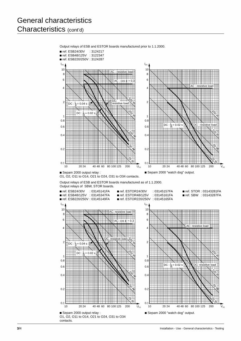
3/4 Installation - Use - General characteristics - Testing
General characteristicsCharacteristics (cont’d)
10 20 40 60 80 100 2000.1
0.2
0.4
0.6
0.8
1
2
4
6
8
10
U(V)
I(A)
DC : L = 0.04 sR
AC: resistive load
AC: cos ϕ = 0.3
500 W
25 W
DC : L = 0.02 sR
DC: resistive load
1254824 10 20 40 60 80 100 2000.1
0.2
0.4
0.6
0.8
1
2
4
6
8
10
V(V)
I(A)
DC : L = 0.02 sR
AC: resistive load
24 48 125
25 W
50 W50 W
100 W
100 W
250 W250 W
DC: resistive load
c Sepam 2000 output relay :O1, O2, O11 to O14, O21 to O24, O31 to O34contacts.
c Sepam 2000 "watch dog" output.
Output relays of ESB and ESTOR boards manufactured prior to 1.1.2000.
c ref. ESB24/30V : 3124217c ref. ESB48/125V : 3122347c ref. ESB220/250V : 3124287
10 20 40 60 80 100 2000.1
0.2
0.4
0.6
0.8
1
2
4
6
8
10
U(V)
I(A)
DC : L = 0.04 sR
AC : resistive load
AC : cos ϕ = 0.3
500 W
25 W
DC : L = 0.02 sR
DC:
1254824 10 20 40 60 80 100 2000.1
0.2
0.4
0.6
0.8
1
2
4
6
8
10
V(V)
I(A)
DC : L = 0.02 sR
AC : resistive load
24 48 125
25 W
50 W50 W
100 W
100 W
250 W250 W
DC : resistive load
resistive load
c Sepam 2000 output relay :O1, O2, O11 to O14, O21 to O24, O31 to O34 contacts.
c Sepam 2000 "watch dog" output.
Output relays of ESB and ESTOR boards manufactured as of 1.1.2000.Output relays of SBW, STOR boards.
c ref. ESB24/30V : 03145141FA c ref. ESTOR24/30V : 03145157FA c ref. STOR : 03143281FAc ref. ESB48/125V : 03145347FA c ref. ESTOR48/125V : 03145161FA c ref. SBW : 03143287FAc ref. ESB220/250V : 03145149FA c ref. ESTOR220/250V : 03145165FA

3/5Installation - Use - General characteristics - Testing
Sepam 2000 logic inputs
connection by 0.6 to 2.5 mm2 wire to CCA 621 terminal
according to Sepam 2000 power supply 24/30 Vdc 48/127 Vdc 220/250 Vdc
consumption 4 mA (4) 4 mA (4) 3 mAlevel 0 < 6 V < 25,4 V < 50 Vlevel 1 > 17 V > 33,6 V > 154 Vpermissible steady state overload 36 V 152 V 275 Vpick up time 10 ms 10 ms 10 msinsulation 2 kV 2 kV 2 kV
Jbus/Modbus communication input
connection cable (CCA 602 or CCA 619 accessory)
transmission asynchronous serial
protocol Jbus/Modbus slave
electrical interface according to EIA- RS 485 standard
maximum distance without repeater 1200 m
number of Sepam 2000s on the line 31 max.
rates 300, 600, 1200, 2400, 4800, 9600 19200, 38400 bits/s
insulation 1 kV rms
power supply
connection by 0.6 to 2.5 mm2 wire to CCA 604 terminal
dielectric insulation 2 kV rms - 1 min.
power supply voltage 24/30 Vdc (5) 48/127 Vdc 220/250 Vdc
permissible variations (3) -20% to +20% -20% to +20% -20% to +10%20 V to 36 V 39 V to 152 V 176 V to 275 V
power supply circuit consumption (Sepam 2000) (1)
power supply voltage 24 Vdc 48 Vdc 127 Vdc 220 Vdc
inrush current 5 A/0.2 s 1 A/0.5 s 1,5 A/0.5 s 1 A/0.2 s
Sepam S26 or S25 all relays deactivated 0.5 A 0.25 A 0.12 A 0.08 ASepam S26 or S25 all relays activated 0.8 A 0.5 A 0.2 A 0.12 A
Sepam S36 or S35 all relays deactivated 0.6 A 0.28 A 0.12 A 0.08 ASepam S36 or S35 all relays activated 1 A 0.6 A 0.22 A 0.13 A
Sepam 2046 all relays deactivated 0.24 A 0.11 A 0.07 ASepam 2046 all relays activated 0.52 A 0.22 A 0.12 A
weight (2) min. max.
Sepam S26 or S25 6 kg 8.5 kg
Sepam S36 or S35 8 kg 10.5 kg
Sepam S46 9.5 kg 10.6 kg(1) the figures are given for:c Jbus/Modbus coupler option included (Subtract 1 W for Sepam 2000 without communication).c TSM 2001 pocket terminal not connected (Add 1/2 W if the pocket terminal is connected).c Sepam S25 or S26 equipped with 2 ESTOR. boardsc Sepam S35 or S36 equipped with 3 ESTOR. boards.c Sepam S46 equipped with 5 ETOR boards.(2) The figures give the weight according to the number of options for each model.(3) correct operation of Sepam is only guaranteed within these ranges.(4) 10 mA for ESB and ESTOR boards manufactured prior to 1.1.2000.(5) not available with Sepam 2000 S46.

3/6 Installation - Use - General characteristics - Testing
General characteristicsQualification tests
This chapter presents the main specified properties(mechanical, electrical, functional, etc...)that are verified during the qualification tests carriedout in the factory ("manufacturer" tests).
It describes:c the content of each test,c the standards and reference documents,c the expected results.
It is divided into seven sections, grouping together the different items involved inproduct qualification by theme:
GeneralDescription of the general conditions which apply to all the tests.
Technological testsTests designed to ensure conformity of device manufacturing(with respect to the manufacturing specifications, company standards,...),and the device's implementation capability (installation, operation,...).
Electrical testsTests related to the protection of people and equipment (grounding continuity,insulation, fuses…).
Performance tests in reference conditionsVerification of special functional features (hardware and software) of the productwhen used in the "reference environment" (i.e. temperature, power supply…using strict tolerances).
Testing of output effects in rated domainsExamination of the rated operating domain (input signals, output loads,power supply...), using one variable at a time.
Effects of the equipment on the environmentTesting of interference (electromagnetic, mechanical...) generated by the product.
Effects of the environment on the equipmentTesting of the product's sensitivity and/or resistance to electromagnetic, mechanical,chemical... interference.
Reference documentsIn order to facilitate reading, only documents of prime importance are succinctlyreferenced in each test description.
For more details, please refer to the appendix.

3/7Installation - Use - General characteristics - Testing
General characteristicsElectrical tests
AimThe aim of these tests is to test the effectivenessof the measures taken to protect peopleand equipment.
Preliminary operating testAim: to ensure the integrity of the item being tested(the test procedure allows the device,its integrated components and remote functions to betested at the same time).
N.B. The test is not exhaustive. It is merely aimed atproviding a good "macroscopic" view of the item beforeand/or after the applicationof potentially destructive stress, in a minimaltest environment.
Grounding continuityAim: to test the continuity of grounding protection.
Reference documents:Standards: IEC 61131-2
Severity: polarizing current: 30 A.
Acceptance criterion: R ≤ 0.1 Ω.
Insulation testingMeasurement of insulation resistance
Aim: to test the constructive integrity of the item beforedielectric stress is applied.
Reference documents:Standards: IEC 60255-5
Special conditions: measurement is performed inboth common and differential modes.
Severity: applied voltage: 500 VDC
Acceptance criterion: Ri ≥100 MΩ.
Dielectric strengthAim: to ensure that the dielectric strength of the insulation complies withspecifications.
Reference documents:Standards: IEC 60255-5
Acceptance criteria:During the test:c no breakdowns, perforations, warpingAfter the test:c the device must correspond to all of its functional specifications.
Severity :circuits test voltage
common mode differential modepower supply 2 kVrms/50 Hz N/A
logic inputs 2 kVrms/50 Hz N/A
analog inputs 2 kVrms/50 Hz N/A (incl. phase currents)
logic outputs 2 kVrms/50 Hz 1 kVrms/50 Hz(*)
setting terminal socket 0.5 kVrms/50 Hz N/A setting(*): with contacts open
Impulse wave withstandAim: to ensure that the device is capable of withstanding high overvoltage for veryshort periods of time without any damage.
Reference documents:Standards: IEC 60255-5Acceptance criteria:During the test:c no breakdowns, performations, warpingAfter the test:c the device must correspond to all of its functional specifications.
Severity :circuits test voltage
common mode differential modepower supply 5 kV 5 kV
logic inputs 5 kV 5 kV
analog inputs 5 kV 5 kV (incl. phase currents)
logic outputs 5 kV N/A
pocket terminal socket 1 kV 0.5 kV
Power supply circuit robustnessShort-circuit current behaviour
Aim: to ensure that the device's circuits are capable of withstanding, withoutdamage, stress caused by short-circuit currents resulting from internal failures.
Acceptance criteria:During the test:c short-circuit current less than 15 A for a maximum of 20 ms.c effectiveness of protective devices.
After the test:c visual check of cabling, connectors, printed circuit paths.c return to normal operation after resetting or replacement of the protective devices.
Polarity reversal behaviour
Aim: to ensure that the device is capable of withstanding, without damage,an accidental power supply polarity reversal.
Reference documents:Standards: IEC 61131-2.
Severity: operation for at least10 seconds with the power supply polarities reversed.
Acceptance criterion:Return to normal operation after the power supply polarities have been correctlyre-established.

3/8 Installation - Use - General characteristics - Testing
General characteristicsPerformance tests in reference conditions
AimThe aim of these tests is to test the special functionalfeatures (hardware and software) of a device in its"reference environment", i.e. temperature, powersupply, etc., using strict tolerances.
Checking of parameter specificationsAim: to check conformity of input/output interfacing characteristics.
Analog input circuitsCompostion of testsFor each type of input (sensors, process, etc.), minimum testing includes:c dynamics and accuracy (examination of the rated domain),c input impedance (examination of the rated domain),c passband.
Logic input circuitsComposition of testsFor each type of input (static relay, etc.), minimum testing includes:c input impedance (exploration of rated domain),c thresholds (high, low, hysteresis),c minimum set-up time (high and low levels).
Logic output circuitsComposition of testsFor static type outputs, minimum testing includes:c output dynamics (I or V),c output compliance (I or V),c influence of load (transition time, over/undershoots),c for datacom: protocol, frequency, gigue, etc.
For relay type outputs, minimum testing includes:c breaking capacity (min.-max. I/V, load impedance),c bounce time.
MiscellaneousInitializationAim: to verify the efficiency of self-testing carried out by the device during start-up.
Downgraded operationAim: to verify the efficiency of self-testing carried out by the device while functioning.
Module interchangeabilityAim: to test maintenance capability.Comments: the tests include:c power source converter,c core-connector.

3/9Installation - Use - General characteristics - Testing
General characteristicsTesting of output effects in rated domains
AimThese tests verify the operation of the device in therated domain of input signal variations, output loads,power supply voltage, etc.
One degree of freedom is variable for each test,the other values being kept at their reference values.
DC power supplyReference documents:Standards: IEC 60255-22-xx, IEC 61131-2for determination of sensitivity limits.
Voltage amplitudeAim: to test the device’s ability to functionwith all acceptable power supply voltages.
Alternating componentAim: to test the device’s ability to functionwith an alternating component (rectifier-batterycharger) superimposed on its DC supply voltage.Severity: alternating component (= ripple batteryvoltage) with frequency >100 Hz and peak-to-peakamplitude = 0.12 UnomComments: the test is performed:c at the extreme limits of the power supply domain.
Fading cancellationAim: to check the device’s ability to maintain operationin spite of power supply micro-outages(source changeover or faulty device nearby).Severity: 10 voltage outages, at minimum 1 sec.intervals, lasting:75 ms for Vpower = Vnom30 ms for Vpower = VminComments: the voltage outages correspond:c first, to an opening in the power supply line(infinite impedance during disturbance),c then, to a shorting of the power supply line(zero impedance during disturbance).
Accidental voltage surgesAim: to test the device’s ability to maintain operationin the presence of transient surge voltage in the powersupply (handling shocks, reactive load switching).Severity: 10 surges, at minimum 1 sec. Intervals,lasting 10 ms, with a maximum slope of 100 V/ms,and maximum amplitude:+ 20 V for Un < 48 V,+ 40 V for Un > 48 V.
Analog input circuitsReference documents:Standards: IEC 60255-6 , IEC 61131-2
Composition of tests: for each type of input (sensors, process, etc.),testing includes, in particular:c behaviour at limits (saturation, voltage limiter operation).c input currents/voltages when saturated.c passband / recovery time.c permissible overload and dynamic thermal limit for sensor inputs.
Logic input circuitsReference documents:Standards: IEC 60255-6, IEC 61131-2
Composition of tests: testing includes, in particular:c static inputs.v input dynamics (examination of saturation).v input currents/voltages (examination of saturation)c relay type inputs.v maximum permissible voltage.v input impedance (voltage limiters, R.L. diodes).v resolution (min. duration of a single-shot input signal).v maximum frequency.
Logic output circuitsReference documents:Standards: IEC 60255-6, IEC 61131-2
Composition of tests:Testing includes, in particular:c static outputs.v effectiveness of protective devices.v maximum length of datacom link.c relay type outputs.v effectiveness of protective devices (damping circuits, overvoltage suppressors).
Ambient temperatureAim: to confirm the hypothesis of temperature rise of the device when being cooledby natural air convection in a confined area.
Reference documents:Standards: IEC 60068-2-2
Comments: This test is complementary to the standardized test describedin the section on "dry heat".

3/10 Installation - Use - General characteristics - Testing
AimThese tests test the level of interference (electrical,electromagnetic, etc.) generated by the device.
DC power supplyReference documents:Standards: IEC 61131-2
Power consumptionAim: to check the conformity of the device to specifications.
Severity: the test is performed at the rated voltages of the two operational domains,i.e. 48 V and 127 V.
Inrush currentAim: to check the conformity of the device to specifications.
Acceptance criteria:
time inrush current maximum peak
50 µs i t < 1.5 ms 10 A
1.5 ms i t < 500 ms 10 A
500 ms i t 1.2* In (1)
(1) In = steady-state current
Radiofrequency interferenceConducted interferenceAim: to check the interference voltage introduced by the device at the energynetwork terminal posts.
Reference documents:Standards: CISPR 22
Acceptance criteria:maximum emission (virtually peak):c 79 dB (µV) from 0.15 to 0.5 MHz,c 73 dB (µV from 0.5 to 30 MHz.
Radiated interferenceAim: to test the electromagnetic field interference radiated by the device.
Reference documents:Standards: CISPR 22
Acceptance criteria:maximum emission (virtually peak) at 10 m:c 40 dB (mV/m) from 30 to 230 MHz,c 47 dB (mV/m) from 230 to 1000 MHz.
General characteristicsEffects of the equipment on the environment

3/11Installation - Use - General characteristics - Testing
Impulse waveAim: to test the device’s immunity when it is submitted to transients caused bylightning and switching (capacitor bank, short-circuit to earth, etc.).
Reference document: Standard: IEC 61000-4-5
Severity
circuits test voltage (test impedance)common mode differential mode
power supply 2 kV (42 Ω) 1 kV (42 Ω)
logic inputs 2 kV (42 Ω) 1 kV (42 Ω)
logic outputs 2 kV (42 Ω) 1 kV (42 Ω)
phase current inputs (ECM) 2 kV (42 Ω) 1 kV (42 Ω)
earth fault current input 2 kV (42 Ω) 1 kV (42 Ω)CT+CSH 30
2 A and 30 A 2 kV (2 Ω) N/Aearth fault current inputs on shielding
voltage inputs 2 kV (42 Ω) 1 kV (42 Ω)
RTD input 2 kV (2 Ω) N/Aon shielding
communication interface 2 kV (2 Ω) N/Aon shielding
AimThese tests check device sensitivity and resistanceto electromagnetic, mechanical, chemical, etc.interference.
Reference documents:Standards: IEC 60255-22-xx for determinationof sensitivity limits.
General characteristicsEffects of the environment on the equipment
Sensitivity to electromagnetic interferenceSensitivity to conducted interference
1MHz damped wave
Aim: to test that the device does not operate in an unwanted manner whensubjected to high frequency transients (switching of auxiliary relays or isolationswitches/circuit breakers).
Reference documents: Standards: IEC 60255-22-1
Severity
circuits test voltagecommon mode differential mode
power supply 2.5 kV 1 kV
logic inputs 2.5 kV 1 kV
analogic inputs 2.5 kV 1 kV (incl. phase currents)
logic outputs 2.5 kV 1 kV
Fast transient burstsAim: to test device immunity when subjected to rapid, repeated electrical transients(inductive load breaks, relay contact bounces).
Reference documents: Stadards: IEC 60255-22-4
Severity
circuits test voltage [coupling]common mode differential mode
power supply 4 kV [direct] 4 kV [direct]
logic inputs 4 kV [direct] 4 kV [direct]
analog inputs 4 kV [direct] 4 kV [direct](incl. phase currents)
logic outputs 4 kV [direct] 4 kV [direct]
pocket 1 kV [direct] 1 kV [direct]terminal 4 kV [capacitive] 4 kV [capacitive]socket

3/12 Installation - Use - General characteristics - Testing
Climatic and mechanical robustness testsForeword: Test sequencec the same device undergoes all the tests.c the sequential testing order complies with the recommendationsin the IEC 60068-1 standard (as testing order maximizes the significanceof the results, each test potentially reveals deterioration caused by previous tests).
ColdAim: to test the device's ability to be used at low temperatures.
Reference documents:Standards: IEC 60068-2-1
Severity:Ad test, without forced air circulation:c device in operation,c temperature: 0 ˚C,c duration: 16 hours,c recovery: 1 hour, device energized.
N.B. The pocket terminal is not subjected to the tests.
Dry heatAim: to test the device's ability to be used at high temperatures.
Reference documents:Standards: IEC 60068-2-2
Severity:Bd test, without forced air circulation:c device in operation,c temperature: 55 ˚C.
Sensitivity to radiated interference
Aim: to test that the device does not operate in an unwanted manner whensubjected to an electromagnetic field of radiation (especially transmitters/receivers).
Reference documents: Standards: IEC 60255-22-3, IEC 61000-4-3
Severity: intensity of field: 30V/m not modulated10V/m amplitude-modulated
Sensitivity to electrostatic dischargesAim: to test that the device does not operate in an unwanted manner whensubjected to electrostatic discharge (operator contact or nearby objets).
Reference documents:Standards: IEC 60255-22-2
Severity: generator load voltage: 8 kV in air6 kV on contact
Testing in a simulated MV environmentAim: to check that there is no nuisance tripping during MV switchgear operations.
Composition of tests: device installed in a cubicle shunt-wired to a high voltagegenerator.
Severity: generator voltage: 30 kV / 50Hz.
Number of operations: 30 closing operations.
General characteristicsEffects of the environment on the equipment (cont’d)

3/13Installation - Use - General characteristics - Testing
Fast temperature variationsAim: to test the device's ability to function duringchanges in ambient temperature.
Reference document: Standards: IEC 60068-2-14
Severity:Nb test, device in operation:c device in operation,c low temperature: 0 ˚C,c high temperature: 55 ˚C,c speed of temperature variation: 5 ±1 ˚C/mn,c duration of exposure at each level: 2 hours,c number of cycles: 2,c recovery: 1 hour, device energized.
N.B. The pocket terminal is not subjected to the tests.
Shocks / Behaviour to shocksAim: to test the device's ability to function in spiteof shocks which may occur during normal operation.
Reference documents: Standards: IEC 60255-21-2
Severity:Class 1:c device in operation,c peak acceleration: 5 gn,c pulse duration: 11 ms,c number of pulses per axis: 3 in each direction.
N.B. The pocket terminal is not subjected to the tests.
Shock resistanceAim: to test the device's ability to withstand shockswhich may occur during transportation or handling.
Reference documents: Standards: IEC 60255-21-2
Severity:Class 1:c peak acceleration: 15 gn,c pulse duration: 11 ms,c number of pulses per axis: 3 in each direction.
N.B. The pocket terminal is not subjected to the tests.
BumpsAim: to check the device's ability to withstand bumpswhich may occur during transportation.
Reference documents: Standards: IEC 60255-21-2
Severity:Class 1:c peak acceleration: 10 gn,c pulse duration: 16 ms,c number of pulses per axis: 1000 in each direction.
N.B. The pocket terminal is not subjected to the tests.
Vibrations / Behaviour to vibrationsAim: to test the device's ability to function in spite of vibrations during normaloperation.
Reference documents: Standards: IEC 60255-21-1
Severity:Class 1:c device in operation,c frequency range: 10 to 150 Hz,c acceleration: 0.5 gn or 0.035 mm (peak values),c number of cycles per axis: 1,c sweep speed: 1 octave/mn ±10%,
N.B. The pocket terminal is not subjected to the tests.
Vibration resistanceAim: accelerated aging test to test the device's ability to withstand weak but longvibrations while in operation or during transportation.
Reference documents: Standards: IEC 60255-21-1
Severity:Class 1:c frequency range: 10 to 150 Hzc acceleration: 1 gn (peak value)c number of cycles per axis: 20
N.B. The pocket terminal is not subjected to the tests.
Damp heatAim: to test the device's ability to be stored under high relative humidity conditions.
Reference documents: Standards: IEC 60068-2-3
Severity:Ca test (continuous test).c temperature: 40 ± 2˚Cc relative humidity: 93% +2/-3%c duration: 56 days.c recovery: 1 hour drying at 55˚C, then 1 hour cooling at 20˚C before final test.
N.B. The pocket terminal is not subjected to the tests.
Salt mist / Test for special use only / Corrosive atmosphereAim: to define the atmosphere to which the device may be exposed in operation and/or storage.
Reference documents: Standards: IEC 60654-4.
Severity:c class 1: clean industrial air.
Enclosure protection degreeAim: to test the protection provided by the enclosure:c for people: against direct contact with energized parts.c or equipment: against solid foreign objects or water.
Reference documents: Standards: IEC 60529
Severity:c front panel: IP51c other sides:v without cabling accessories: IP20v with cabling accessories: IP21.
N.B. The pocket terminal is not subjected to the tests.
Fire behaviour / Glow wire testAim: to evaluate the risk of fire and test extinction of the flames when the product isexposed to abnormal thermal conditions.
Reference documents: Standards: IEC 60695-2-1
Severity:c temperature: 650˚Cc applied duration: 30 ±1 s.
N.B. The pocket terminal is not subjected to the tests.

3/14 Installation - Use - General characteristics - Testing
This chapter presents the main definitionsof dependability and how it is taken into considerationin Sepam 2000, an analysis of the experience gainedfrom feedback on the installed equipment baseand the maintenance of Sepam 2000.
DefinitionsThe definitions which follow are the main definitionsof dependability applied to protective devices:
c The reliability of a protective device is its capabilityof performing its function (or functions) over a givenperiod of time in the operating conditions specified bythe manufacturer, i.e. mainly the capability of trippingwhen required and the capability of not tripping whenunwanted.
c The maintainability of a protective device is mainly itscapability of being easily repaired when maintenancepersonnel dispose of the means prescribed by themanufacturer.
c The availability of a protective device is its capabilityof being in a state to perform its function (or functions)at a given point in time in the operating conditionsspecified by the manufacturer.
These values do not necessarily have the samemeanings, depending on whether they are consideredfrom the viewpoint of the protective device or theelectrical installation.
The availability and maintainability of the protectivedevice contribute to the safety of people andequipment. The reliability of the protective devicecontributes to the uninterrupted availability of thepower supply.
Dependability needs:a trade-off betweentwo unwanted eventsThe mission of protection systems used with circuitbreakers is to guarantee the safety of the installationwhile, at the same time, ensuring the best levelof interrupted power supply.
For Sepam 2000, this mission is conveyed by twoevents, the target occurrence of which should be zero.
c First unwanted event:unwanted tripping of the protective device.An uninterrupted power supply is essential for bothindustrialists and utilities. Unwanted tripping dueto the protective device is liable to generate substantialfinancial losses. This event can be avoided byimproving the reliability of the protective device.
c Second unwanted event:failure of the protective device to trip.The consequences of a fault that is not cleared areliable to be disastrous. For the sake of operatingsafety, the protective equipment must detect powersystem faults selectively and as quickly as possible.
This event can be avoided by improving theavailability of the protective device.
General characteristicsDependability
Consideration of dependabilityin Sepam 2000By the same token as electromagnetic compatibility, dependability is taken intoconsideration right from the start of the development of Sepam 2000.
A Preliminary Risk Analysis (PRA) is used to list the unwanted events linked to thedifferent functions performed by Sepam. Quantified dependability targets are setin accordance with the main unwanted events revealed by the PRA.
Specialized dependability assessment and modeling techniques are used to interpretthe targets in terms of design requirements.
c The predicted reliability analysis determines the failure rate of each Sepam 2000component in use-related conditions. Compendiums of reliability data such as theMilitary Handbook 217 (MIL HDBK 217) and the CNET RDF93 are used for this.
c The Failure Modes, Effects and Criticality Analysis (FMECA) analysis is used toanalyze the effects of a simple component failure on the Sepam 2000 functions andto list the means available to detect them. The FMECA makes it possible to correctcertain risks of malfunctions and specify the self-monitoring functions.
c The unwanted events are modeled to calculate the probability of their occurrenceand to check that the dependability targets are being met.
A large share of the functions of digital protective equipment devices are performedby the software. It is therefore essential to master the quality of the software in orderto attain the overall dependability targets. Software quality is mastered by theimplementation of a rigorous development method.
This method is derived from the recommendations set by the French (AFCIQ) andinternational (IEEE) quality authorities. It stipulates:c the breakdown of development into a series of phases,c the use of design and encoding rules and methods aimed at achieving a high levelof software structuring,c the use of software configuration management tools which allow all the softwarecomponent parts to be managed.
Self-monitoring functionsand fail-safe positionSepam 2000 units are equipped with self-monitoring functions (self-tests),which detect internal failures. The failures are classified in two categories:major failures and minor failures.
c A major failure affects the system’s common hardware resources(e.g. program memory and working memory).
Sepam 2000 is no longer operational. This type of failure may or may not lead to MVfault tripping or unwanted tripping, in which case Sepam 2000 must react quickly andgo into the fail-safe position.
The fail-safe position is characterized by:v lockout in neutral position of the Processing Unit,v an indicator lit up on the front of the device,v a message on the display,v the Watchdog relay in fault position (deactivated),v the relay outputs (logic outputs) in the deactivated position,v a break in the relay output supply for Sepam S46.
c Following a minor failure, Sepam 2000 is in downgraded operation.It can continue to carry out all of its protection functions if the functions affectedare peripheral ones (display, communication).
This classification of failures makes it possible to obtain a compromise betweenbetween a high level of safety and a high level of availability.
The self-tests performed in Sepam 2000 are summarized in the diagramon the next page.

3/15Installation - Use - General characteristics - Testing
Sepam 2000 functional diagram
power supply
processingunit
cartridge(EPROM)
internal Bus
program logiclogic I/O
voltageacquisition
CB controlI/O
analoginputs
communication
display / keypad
Sepam 2000 S46
to level 2
currentacquisition

3/16 Installation - Use - General characteristics - Testing
Standardstitle reference status
vibration, shock, bump and seismic tests on measuring IEC 60255-21-1 1988relays and protection equipment: vibration tests (sinusoidal).
vibration, shock, bump and seismic tests on measuring IEC 60255-21-2 1988relays and protection equipment: shock and bump tests.
electrical disturbance for measuring relays and protection IEC 60255-22-1 1988equipment: 1MHz burst disturbance tests.
electrical disturbance for measuring relays and protection IEC 60255-22-2 1989-10equipment: electrostatic discharge tests.
electrical disturbance for measuring relays and protection IEC 60255-22-3 1989-10equipment: radiated electromagnetic field disturbance tests.
electrical disturbance for measuring relays and protection IEC 60255-22-4 1992equipment: 1 MHz damped oscillating wave tests.sensitivity to fast transient interference tests.
electromagnetic compatibility (EMC) IEC 61000-4-3 1998part 4-3: testing and measurement techniquesimmunity to electromagnetic fieldsradiated at radioelectric frequencies test
single input energising quantity measuring relays with IEC 60255-5 1977dependent specified time.
electrical relays: insulation tests for electrical relays: IEC 60255-6 1988
degrees of protection provided by enclosures (IP code). IEC 60529 1989
programmable logic controllers: equipment characteristics. IEC 61131-2 1992
environmental testing: general and guidance. IEC 60068-1 1988
environmental testing: IEC 60068-2-1 1990-04test A: cold.
basic environmental testing procedures: IEC 60068-2-14 1986test N: change of temperature.
basic environmental testing procedures: IEC 60068-2-2 1974test B: dry heat.
basic environmental testing procedures: IEC 60068-2-3 1969test Ca: damp heat, steady state.
basic environmental testing procedures: IEC 60068-2-52 1984test Kb: salt mist, cyclic (sodium chloride solution).
limits and methods of measurement of radio interference: IEC CISPR 22 1993characteristics of information technology equipment.
test methods IEC 60695-2-1 1994fire behaviour: glow wire test.
operating conditions for measurement and control equipment IEC 60654-4 1987in industrial processes: effects of corrosion and erosion.
Appendix 1: reference documents

4/1Installation - Use - General characteristics - Testing
Testing – setting record sheetsContents
testing – setting record sheets 4/2
commissioning tests 4/2test sheets 4/3setting record sheets 4/6
chapter / page

4/2 Installation - Use - General characteristics - Testing
Testing – setting record sheetsCommissioning tests
Sepam 2000 commissioning does not call forindividual testing of the metering and protectionfunctions.Sepam 2000 has been designed and developed toensure all of the functions:c protection,c metering,c program logic.Each of the functions has been factory-tested inits entirety. In addition, Sepam 2000 has a highperforming self-testing system which continuallychecks function integrity, (e.g. no settings outsidethe tolerance range, etc.).The product is ready to use and commissioninghas been simplified accordingly.
Simple testing of one function ensures the correctoperation of the whole group of functions,provided that the product is installed correctly.
It is therefore sufficient to check the Sepam 2000installation.Checking relates to:c parameter setting,c connection to current, voltage and temperaturesensors,c connection of switchgear control and annunciation.

4/3Installation - Use - General characteristics - Testing
Commissioning testsCheck current and voltage sensor wiring and phase rotation order beforehand.Set the status parameters and set the protections according to the setting record sheet.
type of test scheme result display
Sepam connected to current sensors only (1)
secondary injection I1 = 1 or 5 A B6 primary rated I1 =of rated current I2 = 1 or 5 A current I2 =
I3 = 1 or 5 A I3 =
Sepam connected to current and voltage sensors
3-phase secondary rated current B6 P = + feeder
injection (1 or 5 A)rated voltage Q = +(Uns)
phase shift ϕ = -30° P = - incomerinductive
Q = -
residual current according to assembly
Sum 3I B63-phase secondary rated currentinjection (1 or 5 A) residual I = 0 Ir =
in 1 phase rated current residual I = rated I Ir =(1 or 5 A)
CSH B7primary injection 30 A 28.5 ≤ residual I ≤ 31.5 A Ir =primary injection 0.2 A 0.18 ≤ residual I ≤ 0.22 A Ir =
CT (with CSH 30 or ACE 990) B7secondary injection(with CSH 30) rated current (1 or 5 A) residual I = rated I Ir =primary injection residual I = injected current
residual voltage according to assembly
VT in broken delta B7single-phase residual voltage Vo =secondary injection = phase voltage
VT in star B63-phase secondary residual voltage Vo =injection = phase voltage
logic input / output wiring
check the conformity of logic input and output connection
circuit breaker/contactor program logic
closing by closing button closing of device
control
tripping by tripping button opening of device
control
pilot wire test (standard Sepam)
test the link (KP18) (message) RECEIVE.BI
(on upstream Sepam)
.............................
.............................
.............................
.............................
................................
................................
................................
TEST SHEET Sepam 2000Project : ....................................................................................................
Switchboard: .........................................................................................
Panel: ........................................................................................................
.......................................................................................................................
Type of Sepam 2000
serial number
Uns
3
Uns
3
................................
................................
................................
................................
..............................
..............................
................................
Q = + 3Un.In2
P = + 3Un.In2
P = - 3Un.In2
Q = - 3Un.In2
Tests carried out on:
by:
Comments:
Signature Signature
(1) s
ee “
Test
ing”
doc
umen
tatio
n
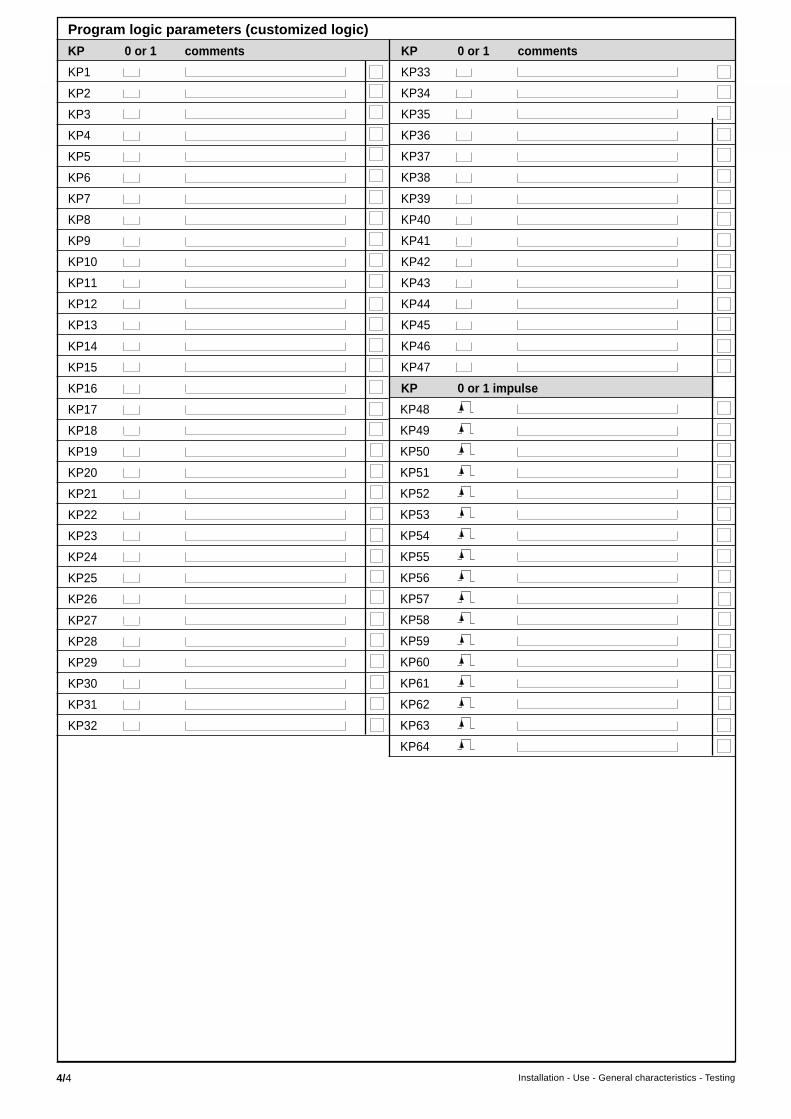
4/4 Installation - Use - General characteristics - Testing
KP 0 or 1 comments
KP33
KP34
KP35
KP36
KP37
KP38
KP39
KP40
KP41
KP42
KP43
KP44
KP45
KP46
KP47
KP 0 or 1 impulse
KP48
KP49
KP50
KP51
KP52
KP53
KP54
KP55
KP56
KP57
KP58
KP59
KP60
KP61
KP62
KP63
KP64
KP 0 or 1 comments
KP1
KP2
KP3
KP4
KP5
KP6
KP7
KP8
KP9
KP10
KP11
KP12
KP13
KP14
KP15
KP16
KP17
KP18
KP19
KP20
KP21
KP22
KP23
KP24
KP25
KP26
KP27
KP28
KP29
KP30
KP31
KP32
Program logic parameters (customized logic)

4/5Installation - Use - General characteristics - Testing
Program logic parameters (customized logic)
time delay (value) comments time delay (value) comments
T1 s T31 s
T2 s T32 s
T3 s T33 s
T4 s T34 s
T5 s T35 s
T6 s T36 s
T7 s T37 s
T8 s T38 s
T9 s T39 s
T10 s T40 s
T11 s T41 s
T12 s T42 s
T13 s T43 s
T14 s T44 s
T15 s T45 s
T16 s T46 s
T17 s T47 s
T18 s T48 s
T19 s T49 s
T20 s T50 s
T21 s T51 s
T22 s T52 s
T23 s T53 s
T24 s T54 s
T25 s T55 s
T26 s T56 s
T27 s T57 s
T28 s T58 s
T29 s T59 s
T30 s T60 s
v tick off the box when the setting is done

4/6 Installation - Use - General characteristics - Testing
SETTING RECORD SHEET Sepam 2000 SubstationProject: .....................................................................................................
Switchboard: .........................................................................................
Panel: ........................................................................................................
.......................................................................................................................
Type of Sepam 2000
serial number
S
Status menu parametersmenu name function
frequency Fn network frequency 50 Hz 60 Hz
phase CT board 2 (ECM or ECA)
ratio In CT rating or CSP (in Amps) A kA
Ib basis current (in Amps) A kA
number number of current sensors I1-I3 I1-I2-I3
Io sensor board 2 (ECM or ECA)
Ino residual current Sum 3I for CTmeasurement Sum1 3I or Sum2 3I for CSP
2 A core bal. CT 30 A core bal. CTCT + CSH 30 for S26, S36
A kAA kA for S25, S35
core bal. CT + ACE 990A kA
max. demand interval max. demand 5 mn 10 mn 15 mn 30 mninterval integration time 60 mn
VT ratio number number of wired VTs V 1U 3U S26, S36 U21 U21-U32 3U S25, S35
Unp rated VT voltsprimary voltage kilovolts
Uns rated VT 100 V 110 V 115 V 120 Vsecondary voltage
Vnso type of residual voltage Sum 3V Uns/ Uns/3measurement
power flow incomer reverses the signs of power Incomer = cables to busbarsdirection feeder and energy measurements Feeder = busbars to cables
oscillography pretrig number of periodsbefore triggering event of thedisturbance recording periods
communi- bauds transmission speed 300 600 1200 2400cation 4800 9600 19200 38400
address Sepam station numberin network
parity transmission format even odd no parity
time tagging synchro type of synchronization via network via input I11used via input I21
events KTS1 to 8KTS9 to 16
N.B. KTS17 to 24For each event, KTS25 to 32choose 0 or 1 KTS33 to 400 = not time-tagged KTS41 to 481 = time-tagged KTS49 to 56all events are set KTS57 to 64to 0 by default I1 I2
I11 to I18KTS33 to 64 for S26, S36 I21 to I28only I31 to I38
3

4/7Installation - Use - General characteristics - Testing
SW2 SW2 SW2
SW1 SW1 SW1
SW1
put an X in the boxto indicate switchsettinge.g. switch set to right
X
s
s
s
s
s
Status menu parameters (cont’d)
menu name function
Microswitch voltage boardsettings
current board board 2 board 3
CT (ECM 1) CSP (ECA) CT (ECM 2)
KP 0 or 1 KP 0 or 1
time delay (value) time delay (value)
T1 recovery ofopen/closed data uponchange in device position
T2 duration of closing order
T3 inhibition of transmit blockinginput after tripping
T5 duration of remote controltripping impulse
T6 duration of remote controlclosing impulse
Sepam 2000 substation program logic parameters
KP16 input I12 BI receipt and inhibitrecloser / inhibit recloser
KP17 display of programmedprogram logic
KP18 BI pilot wire test
KP19 reset operation counter
KP20 reset phase faulttripping counter
KP22 reset specificrecloser counters
KP36 reverse P with annunciation / tripping
KP38 remote setting active / inactive
KP 0 or 1 impulse
KP50 inhibition of disturbance recording records
KP51 automatic triggeringof disturbance recording
KP52 manual triggeringof disturbance recording
KP1 open/close control
KP2 open/close control
KP4 external protection NO/NC
KP6 recloser enabled/disabled
KP7 reclosing cycle 1 inactive / active
KP8 reclosing cycle 2 inactive / active
KP9 reclosing cycle 3 inactive / active
KP10 reclosing cycle 1 inactive / active
KP11 cycle 1 trippingtime-delayed / instantaneous
KP12 cycle 2 trippingtime-delayed / instantaneous
KP13 cycle 3 trippingtime-delayed / instantaneous
KP14 cycle 4 trippingtime-delayed / instantaneous
KP15 definitive trippingtime-delayed / instantaneous
sssss
s
T10 confirmation waiting timeafter successful reclosing
T11 duration of cycle 1 isolation
T12 duration of cycle 2 isolation
T13 duration of cycle 3 isolation
T14 duration of cycle 4 isolation
T15 duration of recloser inhibitionwith manual circuit breaker closing
T16 confirmation of pressure switch fault
T25 tripping pulse
T26 closing pulse
ss
s

4/8 Installation - Use - General characteristics - Testing
Settings made on:
by:
Comments:
Signature Signature
Sepam 2000 Substationfunction identification setting
overcurrent curve Is T
F011
F012
F013
F014
earth fault curve Iso T
F081
F082
F083
F084
undervoltage Us T
F321-341-361
remanent undervoltage Us T
F351
overvoltage Us T
F301
F302
directional overcurrent curve θ Is T
F511-F521
directional earth fault angle Iso T
F501
reverse power Ps T
F531
underfrequency Fs T
F561
F562
overfrequency Fs T
F571
F572
rate of change of dFs/dt T
frequency F581
F582 tick off the box when the setting is done
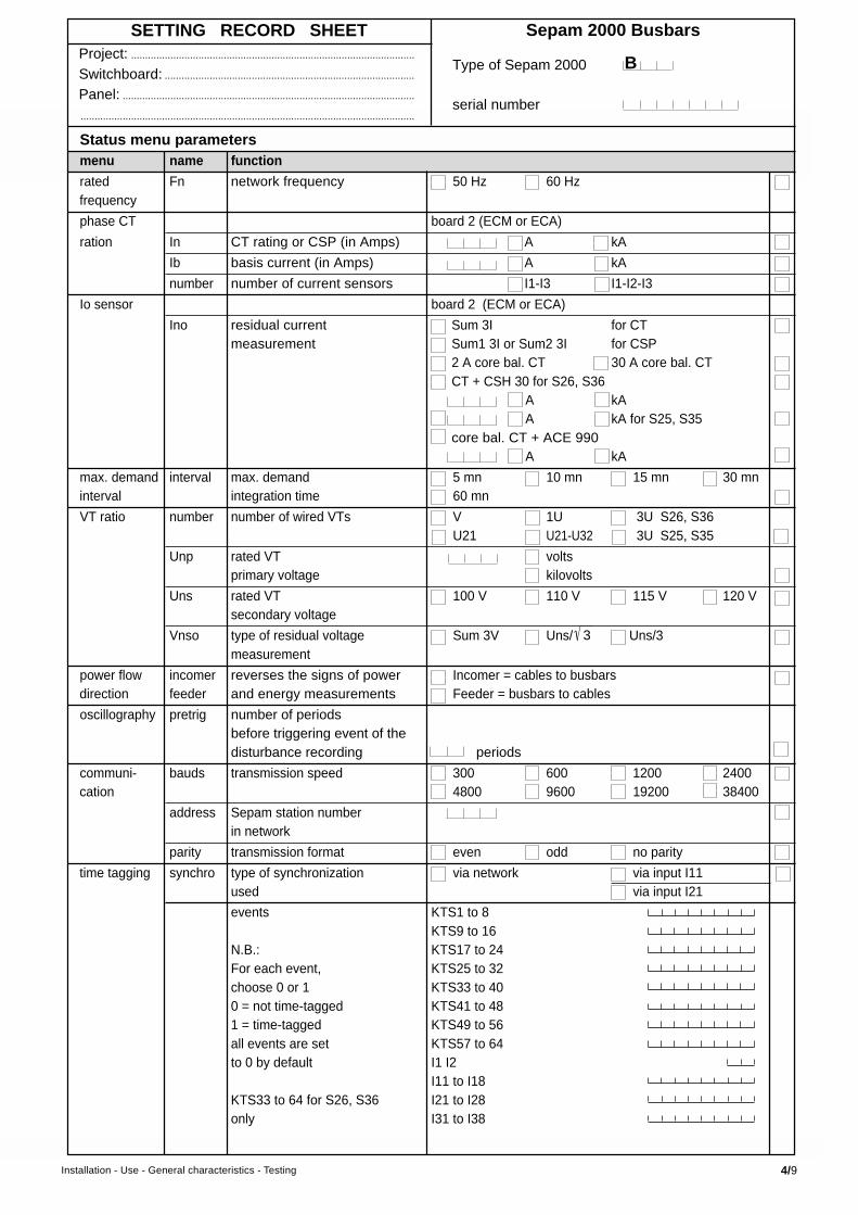
4/9Installation - Use - General characteristics - Testing
SETTING RECORD SHEET Sepam 2000 BusbarsProject: .....................................................................................................
Switchboard: .........................................................................................
Panel: ........................................................................................................
.......................................................................................................................
Type of Sepam 2000
serial number
B
Status menu parametersmenu name function
rated Fn network frequency 50 Hz 60 Hzfrequency
phase CT board 2 (ECM or ECA)
ration In CT rating or CSP (in Amps) A kA
Ib basis current (in Amps) A kA
number number of current sensors I1-I3 I1-I2-I3
Io sensor board 2 (ECM or ECA)
Ino residual current Sum 3I for CTmeasurement Sum1 3I or Sum2 3I for CSP
2 A core bal. CT 30 A core bal. CTCT + CSH 30 for S26, S36
A kAA kA for S25, S35
core bal. CT + ACE 990A kA
max. demand interval max. demand 5 mn 10 mn 15 mn 30 mninterval integration time 60 mn
VT ratio number number of wired VTs V 1U 3U S26, S36 U21 U21-U32 3U S25, S35
Unp rated VT voltsprimary voltage kilovolts
Uns rated VT 100 V 110 V 115 V 120 Vsecondary voltage
Vnso type of residual voltage Sum 3V Uns/ Uns/3measurement
power flow incomer reverses the signs of power Incomer = cables to busbarsdirection feeder and energy measurements Feeder = busbars to cables
oscillography pretrig number of periodsbefore triggering event of thedisturbance recording periods
communi- bauds transmission speed 300 600 1200 2400cation 4800 9600 19200 38400
address Sepam station numberin network
parity transmission format even odd no parity
time tagging synchro type of synchronization via network via input I11used via input I21
events KTS1 to 8KTS9 to 16
N.B.: KTS17 to 24For each event, KTS25 to 32choose 0 or 1 KTS33 to 400 = not time-tagged KTS41 to 481 = time-tagged KTS49 to 56all events are set KTS57 to 64to 0 by default I1 I2
I11 to I18KTS33 to 64 for S26, S36 I21 to I28only I31 to I38
3
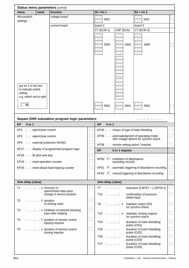
4/10 Installation - Use - General characteristics - Testing
Status menu parameters (cont’d)
menu name function 3U +Vo 1 3U + Vo 2
Microswitch voltage boardsettings
current board board 2 board 3
CT (ECM 1) CSP (ECA) CT (ECM 2)
SW2 SW2 SW2
SW1 SW1 SW1
put an X in the boxto indicate switchsettinge.g. switch set to right
X
SW1 SW1
KP 0 or 1 KP 0 or 1
time delay (value) time delay (value)
T1 recovery ofopen/closed data uponchange in device position
T2 durationof closing order
T3 inhibition of transmit blockinginput after tripping
T5 duration of remote controltripping impulse
T6 duration of remote controlclosing impulse
T7 extension of dF/dT = 1 (KP33=1)
T16 confirmation of pressureswitch fault
T8 s maintain output O33for synchro-check
T10 s maintain closing requestfor synchro-check
T24 duration of load sheddingpulse (O31)
T25 duration of load sheddingpulse (O32)
T26 duration of load sheddingpulse (O33)
T27 duration of load sheddingpulse (O34)
s
s
s
s
s
KP33 choice of type of load shedding
KP35 acknowledgment of operating modewith voltage absent for synchro-check
KP38 remote setting active / inactive
KP 0 or 1 impulse
KP50 inhibition of disturbancerecording records
KP51 automatic triggering of disturbance recording
KP52 manual triggering of disturbance recording
Sepam 2000 substation program logic parameters
KP1 open/close control
KP2 open/close control
KP4 external protection NO/NC
KP17 display of programmed program logic
KP18 BI pilot wire test
KP19 reset operation counter
KP20 reset phase fault tripping counter

4/11Installation - Use - General characteristics - Testing
Sepam 2000 Busbarsfunction identification setting
overcurrent curve Is T
F011
F012
F013
F014
earth fault curve Iso T
F081
F082
F083
F084
undervoltage Us T
F321-341-361
F322-342-362
F241-331-371
F242-332-372
positive sequence Vsd T
undervoltage F381
F382
remanent undervoltage Us T
F351
F251
overvoltage Us T
F301
F302
F311
F312
neutral voltage Vso T
displacement F391
underfrequency Fs T
F561
F562
F563
F564
overfrequency Fs T
F571
F572
rate of change dFs/dt T
of frequency F581
F582
synchro-check F181 dUs dFs dϕs Us high Us low
mode Ta
tick off the box when the setting is done
Settings made on:
by:
Comments:
Signature Signature

4/12 Installation - Use - General characteristics - Testing
SETTING RECORD SHEET Sepam 2000 TransformerProject: .....................................................................................................
Switchboard: .........................................................................................
Panel: ........................................................................................................
.......................................................................................................................
Type of Sepam 2000
serial number
T
Status menu parametersmenu name function
rated Fn network frequency 50 Hz 60 Hzfrequency
phase CT board 2 (ECM 1 or ECA) board 3 (ECM 2)
ratio In CT rating or CSP (in Amps) A kA A kA
Ib basis current (in Amps) A kA A kA
number number of current sensors I1-I3 I1-I2-I3 I1-I3 I1-I2-I3
Io sensor board 2 (ECM 1 or ECA) board 3 (ECM 2)
Ino residual current Sum 3I for CTmeasurement Sum1 3I or sum2 3I for CSP
2 A core bal. CT 30 A core bal. CTCT + CSH 30 for S26, S36
A kAA kA for S25, S35
core bal. CT + ACE 990A kA
max. demand interval max. demand 5 mn 10 mn 15 mn 30 mninterval integration time 60 mn
VT ratio number number of wired VTs V 1U 3U S26, S36 U21 U21-U32 3U S25, S35
Unp rated VT voltsprimary voltage kilovolts
Uns rated VT 100 V 110 V 115 V 120 Vsecondary voltage
Vnso type of residual voltage Sum 3V Uns/ Uns/3measurement
power flow incomer reverses the signs of power Incomer = cables to busbarsdirection feeder and energy measurements Feeder = busbars to cables
oscillography pretrig number of periodsbefore triggering event of thedisturbance recording periods
communi- bauds transmission speed 300 600 1200 2400cation 4800 9600 19200 38400
address Sepam station numberin network
parity transmission format even odd no parity
time tagging synchro type of synchronization via network via input I11used via input I21
events KTS1 to 8KTS9 to 16
N.B.: KTS17 to 24For each event, KTS25 to 32choose 0 or 1 KTS33 to 400 = not time-tagged KTS41 to 481 = time-tagged KTS49 to 56all events are set KTS57 to 64to 0 by default I1 I2
I11 to I18KTS33 to 64 for S26, S36 I21 to I28only I31 to I38
3

4/13Installation - Use - General characteristics - Testing
s
s
s
s
s
s
time delay (value) time delay (value)
T1 recovery ofopen/closed data uponchange in deviceposition
T2 durationof closing order
T3 inhibition of transmit blockinginput after tripping
T5 duration of remote controltripping impulse
T6 duration of remote controlclosing impulse
T16 confirmation of pressureswitch fault
Status menu parameters (cont’d)
menu name function
Microswitch voltage boardsettings
current board board 2 board 3
CT (ECM 1) CSP (ECA) CT (ECM 2)
SW2 SW2 SW2
SW1 SW1 SW1
SW1
put an X in the boxto indicate switchsettinge.g. switch set to right
X
KP 0 or 1 KP 0 or 1
Sepam 2000 transformer program logic parameters
KP1 open/close control
KP2 open/close control
KP4 external protection NO/NC
KP5 Buchholz / thermostat /DGPT NO/NC
KP6 tripping / alarm input I23
KP7 tank earth leakage choice
KP17 display of programmedcontrol scheme
KP18 BI pilot wire test
KP19 reset operation counter
KP20 reset phase faulttripping counter
KP38 remote setting active / inactive
KP 0 or 1 impulse
KP50 inhibition of disturbancerecording records
KP51 automatic triggering of disturbance recording
KP52 manual triggering of disturbance recording

4/14 Installation - Use - General characteristics - Testing
Settings made on:
by:
Comments:
Signature Signature
Sepam 2000 Transformerfunction identification setting
thermal overload Adjust. T1 and T2 OL1 alarm OL2 trip
F431 0
overcurrent curve Is T
F011
F012
F013
F014
earth fault curve Iso T
F081
F082
F083
F084
neutral voltage Vso T
displacement F391
directional overcurrent curve θ Is T
F521
directional earth fault angle Iso T
F501
tank frame leakage curve Is T
F021
neutral curve Iso T
F091
F092
undervoltage Us T
F321-341-361
remanent undervoltage Us T
F351
overvoltage Us T
F301
F302
RTD Ts1 Ts2
F461
F462
F463
F464
F465
F466
restricted earth fault Is
F651 tick off the box when the setting is done

4/15Installation - Use - General characteristics - Testing
SETTING RECORD SHEET Sepam 2000 MotorProject: .....................................................................................................
Switchboard: .........................................................................................
Panel: ........................................................................................................
.......................................................................................................................
Type of Sepam 2000
serial number
M
Status menu parametersmenu name function
rated Fn network frequency 50 Hz 60 Hzfrequency
phase CT board 2 (ECM 1 or ECA) board 3 (ECM 2)
ratio In CT rating or CSP (in Amps) A kA A kA
Ib basis current (in Amps) A kA A kA
number number of current sensors I1-I3 I1-I2-I3 I1-I3 I1-I2-I3
Io sensor board 2 (ECM 1 or ECA) board 3 (ECM 2)
Ino residual current Sum 3I for CTmeasurement Sum1 3I or sum2 3I for CSP
2 A core bal. CT 30 A core bal. CTCT + CSH 30 for S26, S36
A kAA kA for S25, S35
core bal. CT + ACE 990A kA
max. demand interval max. demand 5 mn 10 mn 15 mn 30 mninterval integration time 60 mn
VT ratio number number of wired VTs V 1U 3U S26, S36 U21 U21-U32 3U S25, S35
Unp rated VT voltsprimary voltage kilovolts
Uns rated VT 100 V 110 V 115 V 120 Vsecondary voltage
Vnso type of residual voltage Sum 3V Uns/ Uns/3measurement
power flow incomer reverses the signs of power Incomer = cables to busbarsdirection feeder and energy measurements Feeder = busbars to cables
oscillography pretrig number of periodsbefore triggering event of thedisturbance recording periods
communi- bauds transmission speed 300 600 1200 2400cation 4800 9600 19200 38400
address Sepam station numberin network
parity transmission format even odd no parity
time tagging synchro type of synchronization via network via input I11used via input I21
events KTS1 to 8KTS9 to 16
N.B.: KTS17 to 24For each event, KTS25 to 32choose 0 or 1 KTS33 to 400 = not time-tagged KTS41 to 481 = time-tagged KTS49 to 56all events are set KTS57 to 64to 0 by default I1 I2
I11 to I18KTS33 to 64 for S26, S36 I21 to I28only I31 to I38
3

4/16 Installation - Use - General characteristics - Testing
s
s
s
s
s
s
s
s
time delay (value) time delay (value)
T1 recovery ofopen/closed data uponchange in deviceposition
T2 durationof closing order
T3 inhibition of transmit blockinginput after tripping
T4 external load shedding order
T5 duration of tripping pulse froma remote control order
T6 duration of remote controlclosing impulse
T8 maximum duration of voltagesag enabling restart
T9 restart staggering
T16 s confirmation of pressureswitch fault
KP 0 ou 1 KP 0 ou 1
Sepam 2000 motor program logic parameters
KP1 open/close control
KP2 open/close control
KP3 open/close control
KP4 external protection NO/NC
KP17 display of programmedcontrol scheme
KP18 BI pilot wire test
KP19 reset operation counter
SW2 SW2 SW2
SW1 SW1 SW1
SW1
put an X in the boxto indicate switchsettinge.g. switch set to right
X
not used
Status menu parameters (cont’d)
menu name function
Microswitch voltage boardsettings
current board board 2 board 3
CT (ECM 1) CSP (ECA) CT (ECM 2)
KP20 reset phase faulttripping counter
KP21 reset to zero of running hours counter
KP38 remote setting active / inactive
KP 0 or 1 impulse
KP50 storage of disturbancerecording records
KP51 automatic triggering of disturbance recording
KP52 manual triggering of disturbance recording

4/17Installation - Use - General characteristics - Testing
Settings made on:
by:
Comments:
Signature Signature
Sepam 2000 Moteurfunction identification setting
thermal overload Adjust. T1 T2 OL1 warm state OL2 trip
F431
overcurrent curve Is T
F011
F012
earth fault curve Iso T
F081
F082
negative sequence / curve Is T
unbalance F451
Is ST LT
F441
undercurrent Is T
F221
number of starts n° start per hour n° cold start n° hot start T
F421
positive sequence Vsd T
undervoltage F381
F382
directional earth fault angle Iso T
F501
reverse power Ps T
F531
reactive overpower Qs T
F541
RTD Ts1 Ts2
F461
F462
F463
F464
F465
F466
F471
F472
F473
F474
F475
F476
motor differential Is
F621 tick off the box when the setting is done
locked rotor /
excessive starting time

4/18 Installation - Use - General characteristics - Testing
SETTING RECORD SHEET Sepam 2000 CapacitorProject: .....................................................................................................
Switchboard: .........................................................................................
Panel: ........................................................................................................
.......................................................................................................................
Type of Sepam 2000
serial number
C
Status menu parametersmenu name function
rated Fn network frequency 50 Hz 60 Hzfrequency
phase CT board 2 (ECM 1 or ECA) board 3 (ECM 2)
ratio In CT rating or CSP (in Amps) A kA A kA
Ib basis current (in Amps) A kA A kA
number number of current sensors I1-I3 I1-I2-I3 I1-I3 I1-I2-I3
Io sensor board 2 (ECM 1 or ECA) carte 3 (ECM 2)
Ino residual current Sum 3I for CTmeasurement Sum1 3I or sum2 3I for CSP
2 A core bal. CT 30 A core bal. CTCT + CSH 30 for S26, S36
A KAA KA for S25, S35
core bal. CT + ACE 990A kA
max. demand interval max. demand 5 mn 10 mn 15 mn 30 mninterval integration time 60 mn
VT ratio number number of wired VTs V 1U 3U S26, S36 U21 U21-U32 3U S25, S35
Unp rated VT voltsprimary voltage kilovolts
Uns rated VT 100 V 110 V 115 V 120 Vsecondary voltage
Vnso type of residual voltage Sum 3V Uns/ Uns/3measurement
power flow incomer reverses the signs of power Incomer = cables to busbarsdirection feeder and energy measurements Feeder = busbars to cables
oscillography pretrig number of periodsbefore triggering event of thedisturbance recording periods
communi- bauds transmission speed 300 600 1200 2400cation 4800 9600 19200 38400
address Sepam station numberin network
parity transmission format even odd no parity
time tagging synchro type of synchronization via network via input I11used via input I21
events KTS1 to 8KTS9 to 16
N.B.: KTS17 to 24For each event, KTS25 to 32choose 0 or 1 KTS33 to 400 = not time-tagged KTS41 to 481 = time-tagged KTS49 to 56all events are set KTS57 to 64to 0 by default I1 I2
I11 to I18KTS33 to 64 for S26, S36 I21 to I28only I31 to I38
3

4/19Installation - Use - General characteristics - Testing
Sepam 2000 capacitor program logic parameters
SW2 SW2 SW2
SW1 SW1 SW1
SW1
put an X in the boxto indicate switchsettinge.g. switch set to right
X
Status menu parameters (cont’d)
menu name function
Microswitch voltage boardsettings
current board board 2 board 3
CT (ECM 1) CSP (ECA) CT (ECM 2)
KP 0 or 1 KP 0 or 1 impulse
KP1 open / close control
KP2 open/close control
KP4 external protection NO/NC
KP17 display programmedcontrol scheme
KP18 BI pilot wire test
KP19 reset operation counter
KP20 reset phase faulttripping counter
KP21 running hours counter reset
KP36 choice of number of capacitors
KP37 choice of number of capacitors
KP38 remote setting enable / disable
KP50 inhibition of disturbancerecording records
KP51 automatic triggering of disturbance recording
KP52 manual triggering of disturbance recording
KP54 capacitor 1 switch closing
KP55 capacitor 1 switch opening
KP56 capacitor 2 switch closing
KP57 capacitor 2 switch opening
KP58 capacitor 3 switch closing
KP59 capacitor 3 switch opening
KP60 manual capacitor control
KP61 automatic capacitor control

4/20 Installation - Use - General characteristics - Testing
Status menu parameters (cont’d)
T1 s recovery ofopen/closed data uponchange in deviceposition
T2 s durationof closing order
T3 s inhibition of transmit blockinginput after tripping
T5 s duration of remote controltripping impulse
T6 s duration of remote controlclosing impulse
T7 s duration reclosinginhibition after tripping
T21 s capacitor 1opening time delay
T22 s capacitor 2opening time delay
T23 s capacitor 3opening time delay
T24 s circuit breakeropening time delay
T25 s duration of capacitor 1tripping pulse
time delay (value) time delay (value)
Sepam 2000 capacitor program logic parameters
T26 s duration of capacitor 2tripping pulse
T27 s duration of capacitor 3tripping pulse
T28 s duration of capacitor 1closing pulse
T29 s duration of capacitor 2closing pulse
T30 s duration of capacitor 3closing pulse
T31 s after tripping,duration of inhibitionof capacitor 1 closing
T32 s after tripping,duration of inhibitionof capacitor 2 closing
T33 s after tripping,duration of inhibitionof capacitor 3 closing
T34 s time delay for recoveryof capacitor 1 switchopen/closed information
T35 s time delay for recoveryof capacitor 2 switchopen/closed information
T36 s time delay for recoveryof capacitor 3 switchopen/closed information

4/21Installation - Use - General characteristics - Testing
Settings made on:
by:
Comments:
Signature Signature
Sepam 2000 Capacitorfunction identification setting
thermal overload Adjust. T1 T2 OL1 hot status OL2 tripping
F431
overcurrent curve Is T
F011
F012
earth fault curve Iso T
F081
F082
neutral unbalance curve Iso T
1 capacitor F091
F092
neutral unbalance Is T
3 capacitor F111
F112
F121
F122
F131
F132
undervoltage Us T
F321-341-361
overvoltage Us T
F281
F282
F301
F302
tick off the box when the setting is done

4/22 Installation - Use - General characteristics - Testing
3
Status menu parametersmenu name function
rated Fn network frequency 50 Hz 60 Hzfrequency
phase CT board 2 (ECM 1 or ECA) board 3 (ECM 2)
ratio In CT rating or CSP (in Amps) A kA A kA
Ib basis current (in Amps) A kA A kA
number number of current sensors I1-I3 I1-I2-I3 I1-I3 I1-I2-I3
Io sensor board 2 (ECM 1 or ECA) board 3 (ECM 2)
Ino residual current Sum 3I for CTmeasurement Sum1 3I or sum2 3I for CSP
2 A core bal. CT 30 A core bal. CTCT + CSH 30 for S26, S36
A kAA kA for S25, S35
core bal. CT + ACE 990A kA
max. demand interval max. demand 5 mn 10 mn 15 mn 30 mninterval integration time 60 mn
VT ratio number number of wired VTs V 1U 3U S26, S36 U21 U21-U32 3U S25, S35
Unp rated VT voltsprimary voltage kilovolts
Uns rated VT 100 V 110 V 115 V 120 Vsecondary voltage
Vnso type of residual voltage Sum 3V Uns/ Uns/3measurement
power flow incomer reverses the signs of power Incomer = cables to busbarsdirection feeder and energy measurements Feeder = busbars to cables
oscillography pretrig number of periodsbefore triggering event of thedisturbance recording periods
communi- bauds transmission speed 300 600 1200 2400cation 4800 9600 19200 38400
address Sepam station numberin network
parity transmission format even odd no parity
time tagging synchro type of synchronization via network via input I11used via input I21
events KTS1 to 8KTS9 to 16
N.B.: KTS17 to 24For each event, KTS25 to 32choose 0 or 1 KTS33 to 400 = not time-tagged KTS41 to 481 = time-tagged KTS49 to 56all events are set KTS57 to 64to 0 by default I1 I2
I11 to I18KTS33 to 64 for S26, S36 I21 to I28only I31 to I38
SETTING RECORD SHEET Sepam 2000 GeneratorProject: .....................................................................................................
Switchboard: .........................................................................................
Panel: ........................................................................................................
.......................................................................................................................
Type of Sepam 2000
serial number
G

4/23Installation - Use - General characteristics - Testing
Sepam 2000 generator program logic parameters
KP1 open/close control
KP2 open/close control
KP4 external protection NO/NC
KP5 undervoltage tripping,setting 1
KP6 undervoltage tripping,setting 2
KP7 undervoltage tripping,setting 1
KP8 undervoltage tripping,setting 2
KP9 neutral voltage displacementtripping
KP10 underfrequency tripping
KP11 overfrequency tripping
KP12 generator shutdown by reversepower active
KP13 lockout by undervoltage setting 1
KP14 lockout by undervoltage setting 2
KP15 lockout by undervoltage setting 1
KP16 lockout by undervoltage setting 2
KP17 display of programmed program logic
KP18 BI pilot wire test
KP19 reset operation counter
KP20 reset phase fault tripping counter
KP21 reset to zero of running hours counter
KP33 for G01, G02, G12 used with G00,deactivation of reverse power P and Qfor G00, assignment of outputsO21 to O24
KP34 closing without synchro-checkfor G00, use of I18
KP35 for G03, G04: acknowledgmentof operating mode with voltage absent
KP38 remote setting active / inactive
KP 0 or 1 impulse
KP50 inhibition of disturbance recording records
KP51 automatic triggering of disturbance recording
KP52 manual triggering of disturbance recording
KP 0 or 1 KP 0 or 1
SW2 SW2 SW2
SW1 SW1 SW1
SW1
put an X in the boxto indicate switchsettinge.g. switch set to right
X
Status menu parameters (cont’d)
menu name function
Microswitch voltage boardsettings
current board board 2 board 3
CT (ECM 1) CSP (ECA) CT (ECM 2)
time delay (value) time delay (value)
ss
s
s
s
s
s
T1 recovery of open/closed data uponchange in device position
T2 duration of closing order
T3 inhibition of transmit blockinginput after tripping
T5 duration of remote controltripping impulse
T6 duration of remote controlclosing impulse
T10 maintaining of closingrequest with synchro-check
T16 confirmation of pressure switch fault

4/24 Installation - Use - General characteristics - Testing
Sepam 2000 Generatorfunction identification setting
overcurrent curve Is T
F011
F012
F013
F014
F021
F022
thermal overload Adjust. T1 T2 OL1 alarm OL2 trip.
F431
voltage restrained curve Is T
overcurrent F191
negative sequence / curve Is T
unbalance F451
earth fault curve Iso T R and H2
F061
F062
F063
F064
F071
F072
F091
F092
undercurrent Us T
F321-341-361
F322-342-362
overcurrent Us T
F301
F302
positive sequence Vso T
undervoltage F391
underfrequency Fs T
F561
overfrequency Fs T
F571
directional overcurrent curve angle Is T
F511-F521
directional earth fault θo Iso T
F501
reverse power Ps T
F531
reactive overpower Qs T
F541
RTD Ts1 Ts2
F461
F462
F463
F464
F465
F466 tick off the box when the setting is done

4/25Installation - Use - General characteristics - Testing
Sepam 2000 Generator (cont’d)
function identification setting
RTD (cont’d) Ts1 Ts2
F471
F472
F473
F474
F475
F476
synchro-check F181 dUs dFs dϕs
Us high Us low mode
Ta
restricted earth fault Iso
F641
F651
generator Is
differential F621
Settings made on:
by:
Comments:
Signature Signature
tick off the box when the setting is done

12 / 19993140750A-FART.75751
This document has beenprinted on ecological paper.
Schneider Electric Postal addressF-38050 Grenoble cedex 9Tel: 33 (0)4 76 57 60 60Telex: merge 320842 Fhttp://www.schneider-electric.com
As standards, specifications and designs change fromtime to time, please ask for confirmation of the informationgiven in this publication.
Publishing: Schneider ElectricDesign, production: IdraPrinting:Rcs Nanterre B 954 503 439