Embed Size (px)
Citation preview
Analytica Chimica Acta, 238 (1990) 45-53
Elsevier Science Publishers B.V., Amsterdam
45
Analytical instrument maintenance and its implications
A.A. Davis
ICI Chemicals & Polymers Ltd., Merseyside Operations, Castner Kellner Sire, P. 0. Box 9, Runcorn, Cheshire WA7 4JE (Great Britain)
(Received 3rd April 1990)
Abstract
The various aspects of importance for the maintenance of analytical instruments for process control are discussed.
This discussion is based on practical experience in a large industrial chemical company. Emphasis is placed on the
organizational aspects and the continuous attention that is needed. Also, the significant role of audits is stressed.
Keyword: Process analysis; Instrument maintenance
The aim of this paper is to introduce the sub- ject of analytical instrument maintenance and re- veal some of its implications. Much of the author’s experience has been gained in Castner Kellner Works, which is the largest within the Merseyside Operations Group of ICI Chemicals & Polymers.
The principle products are chlorine and its as- sociated by-products, i.e., “caustic” (sodium hy- droxide) and hydrogen. Considerable care has to be taken with the production of such chemicals, hence the factory is extensively automated from an analytical instrumentation standpoint.
During the past 10 years, analytical instrumen- tation has grown in stature and is now recognized and accepted as a most important branch of in- dustrial instrumentation. Progress in technology has brought about significant improvements in design, materials of construction and in the
hardware associated with sample systems. These areas of improvement, when combined, have con- tributed to greater reliability and integrity of ana- lytical systems and as a consequence the role now played by the analyser is of greater significance and importance in industrial processes.
As the reliability has improved and confidence has been gained, more analysers have been intro- duced on-line to control difficult plant parame-
ters, thus contributing to improved standards of quality control, safety and more efficient use of resources. This is a significant change in emphasis as opposed to the past, when equipment of this nature was used merely to guide plant manage-
ment with product quality control.
FACTORY SCENE
Today’s labour costs are high and often re- sources are limited in both quantity and quality. To remain competitive, is it necessary to function with a lean yet efficient and well trained work-
force. Ways of overcoming skill shortages must be sought in order to alleviate the problems created
as technology advances and equipment becomes more complex and difficult to maintain.
It is common knowledge that many factories
have a number of analytical systems that have fallen into disrepute, much to the annoyance of process management. Reasons for failure can be usually classified into two groups: problems asso- ciated with hardware, such as poor analyser de- sign, overcomplex systems, poor sampling tech- niques and incorrect or unsuitable materials of construction, and problems associated with peo-

46 A.A. DAVIS
ple, such as lack of training, lack of commitment and a shortage of qualified artificers and techni- cians.
In addition, when substantial capital invest-
ment programmes are taking place, priorities are generally channelled towards completion of the general instrumentation to the exclusion of the analysis systems. The author believes that both aspects of the work should proceed along parallel paths so that both the general and analytical sys- tems are completed to meet plant requirements. In some instances analytical systems may form part of a control or shutdown system, in which case the complete loop should be commissioned at the same time.
Usually when commissioning a chemical plant, it is broken down into “key” sections, e.g., com- pression, liquification and drying. Each section will have its own instrumentation, both general
and analytical, which should be grouped together to form “systems’, each system being commis- sioned in accordance with an established plan.
It is well known that analytical instruments are difficult to maintain; a solution which went some way towards solving the maintenance problems associated with this particular type of technology was to create a “specialist group”, the remit of the group being to look after all aspects of mainte- nance and development work throughout the fac- tory.
A section was established complete with En-
gineer and Foreman to carry out the day-to-day and routine maintenance work. It was considered necessary to choose a Foreman for his leadership and man-management skills rather than for his technical knowledge, and the Engineer leading the group would supply technical “back-up”.
With this type of work there are many routine operations which have to be carried out frequently (e.g., adjusting sample flow-rates, removing bloc- kages). These essential but mundane tasks tend to be neglected if personnel remain unsupervised (people tend to do what they want to do in prefer- ence to doing what they are told). Experience has shown that it is of paramount importance that these simple tasks are dealt with and problems are rectified as soon as possible. If analytical systems
are left unattended for longer than 2-3 days,
considerable effort is required to bring the equipment back to a healthy state (this can often necessitate several weeks’ work). It is therefore
easily demonstrated that attention to detail is vital, especially when analysers are carrying out major control functions on large capital plants, the im- plication being that long shutdown periods/delays are unacceptable.
It is this attention to detail which divides the
thin line between success and failure, and having a Foreman following the correct guidelines is there-
fore a vital part of the organization.
STAFFING REQUIREMENTS
Before creating a maintenance organization it is essential to have a purpose and a set of principles against which to work. For example, improve the quality of analyser systems; assess the present needs and future requirements; determine stan- dards which are consistent across the site; estab- lish the correct maintenance level; set up record- ing/back-up systems; and raise the capability of personnel through experience and training.
In order to carry out the work, an organization was devised to meet the requirements of the above
principles (see figs. 1 and 2). A small number of technicians and artificers
were recruited from within the Instrument/
Electrical Department to form the nucleus of the specialist group, the group being supplemented by contractors employed from an outside company. Contractors are mainly employed to carry out construction work and are recruited in accordance with the needs of the business (numbers vary in accordance with work loading). The technicians and artificers concerned have received training to
ENGINEER
I..; Fig. 1. Structure manning requirements.

ANALYTICAL INSTRUMENT MAINTENANCE AND ITS IMPLICATIONS 47
Fig. 2. Organizational requirements.
“practitioner level” (average level of competence) to deal with the many diverse and difficult situa- tions which arise. “In-house” on-the-job training is carried out, supplemented by courses run by the company and instrument manufacturers. Within the group both the technicians and artificers are expected to carry out maintenance and develop- ment/commissioning work on a rota basis.
All analysis systems are maintained and perfor- mance is monitored for a period of 6 weeks prior to final acceptance and handover. If any faults due to either faulty design or manufacture appear during this period, then these problems are re- ferred back either to the design group responsible or to the manufacturer. A 6-week “running in” period is chosen because it is considered long enough to reveal component failures and to show any design weakness. In addition, the process per- sonnel operating the plant will be able to assess the credibility of the instrument and whether the equipment is performing to the design specifica- tions.
A “bath-tub” curve can be used to display the mortality rate, life expectancy and wear-out phase of an analyser (Fig. 3). How far the “bath-tub” characteristic applies to process analysers may be a matter of debate and no doubt many mainte- nance engineers can readily quote instances where, for example, serious process malfunction or maloperation has caused a large increase in failure rate of some of the analytical systems, but the author believes that on a well run plant which has itself passed into the useful life period, the instru- mentation will have a “useful life” phase.
WORK
Maintenance requirements should be based on an understanding of how critical the equipment is to the plant concerned. The systematic application of maintenance procedures is aimed at providing the correct balance between cost-effective reliabil- ity of equipment and maintaining confidence and credibility in the measuring/ alarm systems, par- ticularly for those systems which require attention to ensure correct functioning, for those system which, if allowed to fall into disrepute, lose credi- bility, for those system where “fail to danger” (i.e., unrevealed) faults could prevent the trip/alarm systems functioning on demand, and to provide fault records which improve perfor- mance and hence enable more informed judge- ments to be made on frequency and scope of checks.
PROTECTIVE SYSTEM
All protective systems, as the term implies, are installed to perform a specific task. As a result there are some key factors which need to be ad- dressed: first, capability (to do the job): range; response time; accuracy of measurement; and set point selection; and second, reliability: confidence in measured value; quality of display, e.g., graphics, indicator/ recorder; fractional dead time; and demand rate on alarm system.
The justification for each installation/loop usu- ally emanates from a hazard and operability study with each analytical system being designated either
"Year-out" phase
"Useful life" random failures .
I I ,
I
I I )
Time (years)
Fig. 3. “Bath-tub” characteristics.

48
hazard justified (minimize likelihood and conse- quences of hazard) or operability justified (im- prove plant performance).
Hazard-justified systems Such systems will be installed on plants where
the potential for serious danger exists, e.g., toxic gas leak or pollution of the environment.
Operability justified systems These are systems installed to assist process
operators in the operation of the plant. The major- ity of systems will fall into this category.
Special maintenance These systems depend on local management
requirements, e.g., mass balance and accounting.
Hazard summary Control measures and a hazard summary are
given in Tables 1 and 2.
MAINTENANCE
With process analytical systems breakdowns are inevitable; 85% of faults can be related to sample systems and associated hardware and the remain- ing 15% to the analyser itself.
It is essential that the sample systems and installations follow a check list (see Table 3). The
introduction of such a list is one way of drawing the designers’ attention to detail which should be
TABLE 1
Control measures
Preventive
Accurate control
Density meters
Katharometers
Accuracy/reliability
Confidence
Legibility of information
Interpretation of
readings
Corrective Emergency
Intervention Safety
Radioactive Gas alarms
alarms
pH alarms
Infrared
alarms
Reliability FDTs ’
Speed of detection
Speed of intervention
a FDT = Fractional dead times.
A.A. DAVIS
TABLE 2
Hazards summary
Preventive
measures
Corrective
measures
Emergency
measures
Means for
ensuring safe
operation under
normal operating
conditions,
i.e., prevents the
initiation of a
sequence of events
that could lead
to a hazardous
event
Means to avoid
an unprevented
disturbance
leading to loss
of containment
Examples: Examples:
Control-loop Alarm/operator
procedure action
Design detail Trip system
inspection Dump tank
analysis Relief system
Means adopted
for reducing
the scale of con-
sequences, i.e.,
reduce amount
discharged or
effects following
discharge
Examples:
Bunding (area
of containment)
Water curtains
Remote shutdown
valves
Restrictor plates
Gas alarms
Emergency
procedures
obvious but is often overlooked. Therefore, at the design stage of a critical loop, consideration should be given to duplicating and making independent
the sample point and sampling systems including the primary measuring devices provided that fi- nance permits. This is particularly important when installations are required to meet pollution and environmental legislation, in which event the sys- tems must be of the highest integrity and reliabil-
ity. If duplicate systems are chosen, they must be
designed in such a way that the stand-by system can be switched into service without delay and the faulty equipment can be readily and easily re- moved for repair. When servicing duplicate sys-
tems, it has been found advantageous to carry a “serviced spare” which can be fitted into the loop at very short notice.
There are several important advantages to be gained from adopting the serviced spare philoso- phy. Better quality repairs can be effected in a workshop than in the field. This is especially so
with pH measurements. These systems are of high impedance and servicing equipment of this nature

ANALYTICAL INSTRUMENT MAINTENANCE AND ITS IMPLICATIONS 49
TABLE 3
Sampling systems and hardware check list
Sample point
Wherever possible should be accessible.
Most suitable location on vessel or pipe should be chosen to
avoid fouling.
To be large enough bore to prevent blockages occurring, pre-
ferably not less than 1 in NB (nominal bore: internal pipe
diameter).
Access platforms should be provided where necessary.
Sample loop Most suitable material of construction for pipework valves and
fittings to suit particular application.
Loop should be kept as small as possible to avoid
distance/velocity lags.
Bypass “fast flow” sample loops should be considered.
Filtering should be considered if applicable.
Exit sample lines should be piped back into plant stream or
alternatively the effluent should be scrubbed before disposal
down any drains.
Where a nitrogen or air purge is used to flush sample lines,
permanent connections must never be made. It is vital that all
purge lines so used are disconnected after use.
Cabinets
Fire-retardant fibre-glass boxes with polypropylene hinges and
stainless-steel catches are to be recommended; alternative
hinges and catches should be chosen to suit the particular
environment for which they are intended. A stay or chain
should be fitted to any hinged doors to prevent them becoming
detached.
Care should be taken to select a box of adequate strength and
dimensions. It is preferably to use boxes which have rein-
forcement built into the fibre-glass (e.g., l&in thick plate
built into base of box for attachment and support).
Cabinets should. be mounted preferably on their own rigid
pedestal at a realistic height and in a location free from
vibration. Access should be left to rear of cabinet.
Electric or steam heating should be used if applicable to
prevent freezing, etc.
Purging cabinets with works air or nitrogen if applicable.
Layout of equipment inside cabinet
Equipment mounting boards should be easily removable and
accessible.
Material or mounting board should suit the particular environ-
ment.
All bolts and screws securing hardware to board should remain
captive.
All incoming and outgoing pipework should be fitted via
detachable bulk-head fittings through a manifold block bolted
to the side of the cabinet.
Correct materials or construction for all hardware, i.e., valves,
rotameters, pipes.
Drip trays and drains should be fitted to all wet analysers.
TABLE 3 (continued)
Services
Electrical:
All electrical equipment should be divorced from sample
equipment where possible.
All electrical connections should be glanded into cabinet
via sealed junction boxes to prevent ingress of weather.
All wiring must conform to particular factory safety re-
quirements; details of specification are available from the
Factory Electrical Engineer.
Plumbing:
All pipework and ancillary equipment supplies, etc., i.e.,
instruments’ air, water, nitrogen and plant samples must be
rigidly piped using the correct materials of construction
and all being properly clipped and bracketed to suit the
particular application. If in any doubt the particular plant
process manager should be consulted.
Safety:
It is most important that safety is always borne in mind.
The Factory Safety Officers should always be contacted if
ever in doubt.
in the field can only lead to disaster. The serviced spare can be installed without delay. The broken equipment can be repaired at leisure.
Planned maintenance is advocated as the best form of preventive maintenance. This mainte- nance is carried out on a routine basis from a series of schedules designed to meet the needs of the installation, the maintenance frequency being
decided by experience and recommendations made by hazard studies, etc. The maintenance takes the
form of weekly, monthly, 3-monthly and yearly checks. This work is preplanned by an instrument planner in conjunction with the Instrument Fore- man, the schedules and testing frequency being
decided by the Engineer in conjunction with the Plant Manager.
To enable a schedule and testing system to
work effectively, it is of paramount importance that feedback is received from the artificers and
technicians carrying out the work and records are kept, drawing and maintenance instructions are kept up to date and paperwork is kept to a mini- mum.

1. DOES THE SCHEDULE WCUPIENTATION REQUIRE “OoIPIC*TION
(Y/N) IF YES, ACTIONS TAKEN OR CONT*CTS N*IIE AND EXTENSION:
3. FAULT HISTORY ENTERED INTO IRIS:
BY (SIGNATURE) DATE
Fig. 4. Computer list of job methods and schedule.

ANALYTICAL INSTRUMENT MAINTENANCE AND ITS IMPLICATIONS 51
ALLOCATION OF WORK SCHEDULES
A computer-based maintenance information package developed within the C&P Division known as a Maintenance Management System is used to initiate the maintenance work. The system consists of the following: full plant inventory; call-up system for all routine work; task specifica- tion data library; daily and long-term planning facility; and on-line history.
The system makes extensive use of on-line transactions for all the above functions supported by batch programs to produce printed reports or carry out tasks that do not need an immediate response. All the Maintenance Management Sys- tem transactions are linked together to allow the user to move continuously through the string of transactions.
Having decided the maintenance schedule and frequency of checking for all the analysers on the plant, job methods are written, detailing the steps to execute the work. The above information is programmed into the computer, which then auto- matically prints out the job methods and schedule listing the analysers to be checked at a particular time (see Fig. 4). The foreman receives the infor- mation and hands it to the control technician or artificer who has been designated to carry out the work.
As the schedule will contain some critical loops and is most likely to contain an alarm/trip, authorization and approval from process must be sought to ensure plant is in safe condition before commencing work.
Should a major defect be apparent during the course of the work, this is attended to im- mediately. Faults of a minor nature are noted on a report sheet which is returned to the Foreman/ Planner when the schedule is completed. It is the Foreman’s responsibility to review outstanding faults and plan for completion as and when labour and materials are available in line with the plant’s requirements. Information is selected from every work order and passed to an on-line history record system which provides useful data for future anal- ysis.
AUDITS/MONITORING OF STANDARDS
To apply frequent routine proof testing is ex- pensive, which is often overlooked. Once a main- tenance organization has been established, there should be rigorous monitoring of procedures to ensure that what has been intended has actually been carried out.
Audits can play a significant and prominent part in establishing whether procedures are in place and also highlight defects in equipment as site visits are made. The author considers that auditing should be carried out by a “team” and attaches considerable importance to the “team” make-up and the personnel involved. The team should consist of engineers and Foreman of mixed disciplines possessing the necessary skills and the experience to expose and probe in depth, thus revealing problems which may not be apparent to the owner of the section/plant being audited. It is to be recommended that one of the team members is a “visiting” engineer who is not normally asso- ciated or involved with the day-to-day running of the section or plant being audited.
Analytical system audits should be carried out annually to derive maximum benefit. If a greater time period is allowed to elapse then equipment could be falling into disrepute because the equipment is no longer useful, corrosion and the harsh environment have taken their toll and checks are too infrequent and or of an inadequate stan- dard.
The benefits of an audit are twofold: it gives the opportunity to vet both the equipment and the paperwork systems to make certain they are up to date and adequate, and it provides the opportun- ity to review the usefulness and value of the equipment and to review the availability/ suitability of maintenance resources, both human and financial. Auditing shows up weakness and inefficiency, hence recommendations which arise as a result should be dealt with promptly.
If equipment is never tested, one day it will fail, possibly undetected, and the consequences of such malfunction could ultimately lead to a serious incident. Hence auditing should question spurious
52 A.A. DAVIS
alarms and trips in order to minimize the risk of neglecting genuine demands on the system.
DEVELOPMENT WORK
Development work is generated in two ways: it is either initiated within the works or takes the form of new capital projects. When the work is initiated within the works it is usually comes as a direct request from plant management or the re- sult of a hazard study. Large captial projects are designed and handled by the Engineering Depart- ment.
In order to minimize design faults or to make changes to designs which experience proves neces- sary, close collaboration between site and the En- gineering Department is of prime importance. If possible, the analysis units should be assembled on the site for which they are intended. The be- nefits of this are twofold: personnel can follow the project through from the construction phase to commissioning and on through maintenance; and this gives the personnel a greater sense of achieve- ment as they will be maintaining equipment that they themselves have fabricated. Equipment built in this way is very much easier to commission and has fewer faults.
It is appreciated that owing to a shortage of manpower and skills it is not always possible to use the above strategy, in which case the sooner the site personnel are allowed to work alongside the contractor or site commissioning team, the more successful the work will be.
RUNNING COSTS OF ON-LINE ANALYSERS
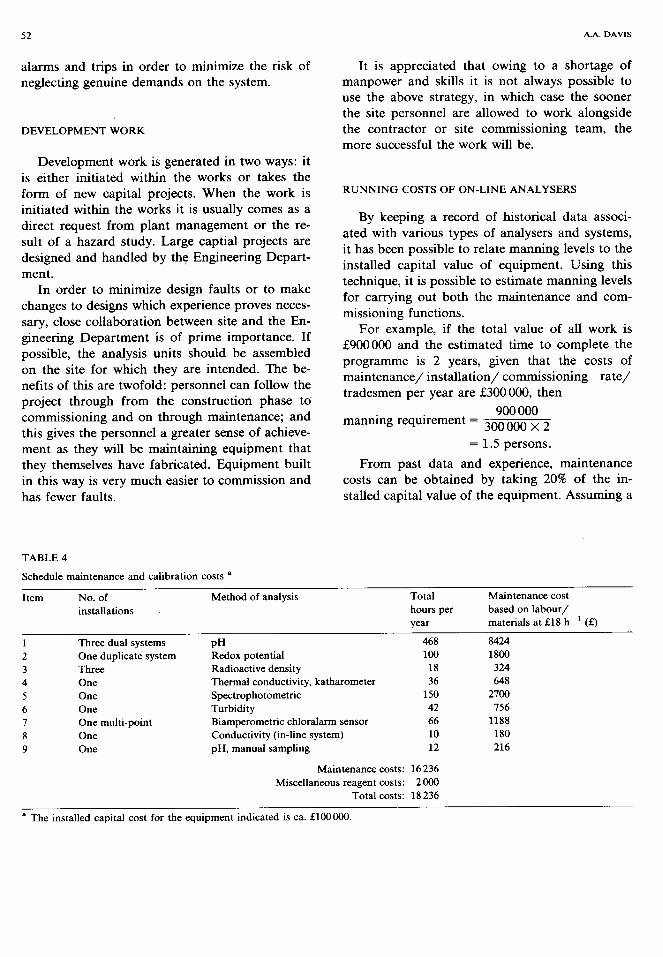
By keeping a record of historical data associ- ated with various types of analysers and systems, it has been possible to relate manning levels to the installed capital value of equipment. Using this technique, it is possible to estimate manning levels for carrying out both the maintenance and com- missioning functions.
For example, if the total value of all work is $Z900000 and the estimated time to complete the programme is 2 years, given that the costs of maintenance/ installation/ commissioning rate/ tradesmen per year are S300000, then
900 000 manning requirement = 3ooOOo x 2
= 1.5 persons.
From past data and experience, maintenance costs can be obtained by taking 20% of the in- stalled capital value of the equipment. Assuming a
TABLE 4
Schedule maintenance and calibration costs a
Item No. of Method of analysis Total Maintenance cost
installations hours per based on labour/ year materials at El8 h-’ (f)
1 Three dual systems PH 468 8424
2 One duplicate system Redox potential loo 1800 3 Three Radioactive density 18 324 4 One Thermal conductivity, katharometer 36 648 5 One Spectrophotometric 150 2700 6 One Turbidity 42 756 7 8 9
One multi-point Biamperometric chloralarm sensor 66 1188 One Conductivity (in-line system) 10 180 One pH, manual sampling 12 216
Maintenance costs: 16 236 Miscellaneous reagent costs: 2000
Total costs: 18 236
a The installed capital cost for the equipment indicated is ca. f100000.
ANALYTICAL INSTRUMENT MAINTENANCE AND ITS IMPLICATIONS 53
f500000 total value over a 2-year period, the maintenance costs per year would be
&500000x20x1 100x2
= g50 000
An approximation of spares costs can be obtained by taking 20% of the installed capital value.
It must be appreciated that the cost of analyti-
cal equipment varies widely, usually in accordance with its complexity. The figures quoted above are by no means precise; they are intended only as a guide and a base upon which a maintenance organization can be founded.
An attempt has been made to list the installa-
tion and maintenance costs for a variety of on-line process analytical equipment which one could ex- pect to find at the sites of some of the larger chemical companies (Table 4). The costs are based on data acquired over a number of years and updated in the light of experience gained. The time spent on each of the systems is for an average level of maintenance, the standard such that it satisfies the criteria laid down for the hazard-
justified or operability-justified systems. Failure to maintain to the desired standard would be a seri-
ous threat to production or could result in a serious hazard or gas escape.
It is often said that the success of a system can
be judged by the number of complaints received. However, it is preferable to apply preventive maintenance rather than adopting a “leave it until it fails” attitude.
It must be appreciated that the cost of analyti-
cal equipment varies widely and that very few systems will be built using the same manufacturer’s equipment and components (most systems are tailor-made to suit individual conditions). Differ- ent site conditions could distort labour costs.
All the evidence to data points to the fact that
in most instances “on-line” wet chemical analysers
(those employing reagents to cause reactions, col- our changes, temperature changes, etc.) are in general (there are exceptions) unreliable, difficult and in some instances hazardous to maintain. In addition, other facilities such as the provision of a regular and reliable supply of reagents and calibration sample solutions are necessary; such a service in itself is often expensive and difficult to
provide. The author’s own experience is that if standard reagents can be purchased either from the manufacturer or a reliable alternative chemical
reagent supplier, this can be of considerable be- nefit. Using a works laboratory to provide a service often has its problems unless adequate warning can be given as to when the reagents are required.
Some wet chemical analysers require weekly replacement of reagents, others monthly, and this should be catered for when the preventive mainte- nance schedule for the analyser is first established.
It must be remembered reagents have a “shelf- life”, in which case if there is any doubt a reagent should be discarded and a freshly prepared solu- tion obtained.
Wet chemical analysis equipment is usually complex and time consuming to maintain. The technicians who service this type of equipment should possess a high degree of skill and experi-
ence in addition to being dedicated to analytical work. Owing to skills shortage, in the future alter- native ways of providing this more specialist type of maintenance will have to be sought. Instrument
manufacturers and specialist contracting organiza- tions may be called upon to supplement existing
work forces in order to provide cover on a 24-h basis.
Care should be taken in accurately specifying the scope of the work in order to prevent any misunderstanding occurring. Also, tight supervi- sion will be necessary to ensure that standards are of the highest order. In order to achieve this objective, “fixed-price” maintenance contracts will have to be sought and negotiated. Suitable con- tractors should be invited to tender in order that
contracts can be scrutinized to ensure technical
competence and scale of economy. In conclusion, experience has shown that the
systematic application of procedures by a special-
ist team is the best way of providing a reliable and effective maintenance service for analytical instru- ments.
The author thanks members of the Electrical/ Instrument Section and other members of the Castner Kellner Works staff for their kind assis- tance and support throughout this work.