Embed Size (px)
Citation preview

DISTRIBUTION STATEMENT: Approved for public release; distribution is unlimited.
Teledyne Brown Engineering Contract Number NNM07AB33T, NASA MSFC ER-20.
ANALYTIC MODELING OF PRESSURIZATION AND CRYOGENIC PROPELLANT
CONDITIONS FOR LIQUID ROCKET BASED VEHICLE DESIGNS
Jeremy H. CorpeningTeledyne Brown Engineering/NASA MSFC ER-22
Huntsville, Alabama
ABSTRACT
An analytic model for pressurization and cryogenic propellant conditions during all mission phases of any liquid rocket based vehicle has been developed and validated. The model assumes the propellant tanks to be divided into five nodes and also implements an empirical correlation for liquid stratification if desired. The five nodes include a tank wall node exposed to ullage gas, an ullage gas node, a saturated propellant vapor node at the liquid-vapor interface, a liquid node, and a tank wall node exposed to liquid. The conservation equations of mass andenergy are then applied across all the node boundaries and, with the use of perfect gas assumptions, explicit solutions for ullage and liquid conditions are derived. All fluid properties are updated real time using NIST Refprop.1 Further, mass transfer at the liquid-vapor interface is included in the form of evaporation, bulk boiling of liquid propellant, and condensation given the appropriate conditions for each. Model validation has proven highly successful against previous analytic models and various Saturn era test data and reasonably successful against more recent LH2 tank self pressurization ground test data. Finally, this model has been applied to numerous design iterations for the Altair Lunar Lander, Ares V Core Stage, and Ares V Earth Departure Stage in order to characterize Helium and autogenous pressurant requirements, propellant lost to evaporation and thermodynamic venting to maintain propellant conditions, and non-uniform tank draining in configurations utilizing multiple LH2 or LO2 propellant tanks. In conclusion, this model provides an accurate and efficient means of analyzing multiple design configurations for any cryogenic propellant tank in launch, low-acceleration coast, or in-space maneuvering and supplies the user with pressurization requirements, unusable propellants from evaporation and liquid stratification, and general ullage gas, liquid, and tank wall conditions as functions of time.
INTRODUCTION
Numerous analyses and models exist for pressurization and tank thermodynamics for launch vehicles using cryogenic propellants. These models date back to those used on Saturn era stages such as the S-IC, S-II, and S-IVB. Also, models for existing flight vehicles such as the Space Shuttle and Delta IV are validated with numerous flight data and produce highly accurate results for the respective vehicle. Further, models exist for design and analysis of vehicles yet to fly such as Ares I. One such model, ROCETS, has the major disadvantage of the inability, to date, to calculate mass transfer from evaporation, liquid bulk boiling, or condensation.2 The major similarity to note on all these launch vehicles is the short duration of cryogenic storage and usage. The Ares V Core Stage falls into this category as well. However, the Ares V Earth Departure Stage (EDS) and Altair Lunar Lander both currently require multiple days of in-space coast, a drastic mission and analysis difference when compared to the previously mentioned launch vehicles. A rigorous and flexible pressurization and tank thermodynamics model for multiple days of in-space coast was lacking and critical to design iterations and maturation for Ares V EDS and Altair. This was the impetus for the model development contained herein.
https://ntrs.nasa.gov/search.jsp?R=20100022074 2018-11-20T19:18:38+00:00Z

Page | 2
NOMENCLATURE
Area Gas Constant
Acceleration Temperature
Heat Transfer Coefficient Wall Thickness
Constant Pressure Specific Heat Internal Energy
Constant Volume Specific Heat Volume
Time Step Volume Rate of Change
Enthalpy Work Rate
Thermal Conductivity Prandtl-Grashof Number
Length Mass Fraction
Molecular Weight Mole Fraction
Mass Thermal Coefficient of Volumetric Expansion
Mass Flow Rate Viscosity
Heat Transfer Exponent Density
Pressure Density Rate of Change
Heat Transfer Rate
RESULTS AND DISCUSSION
The results and discussion section is divided into four major sub-sections. Those are Model Development, Model Validation, Preliminary Uncertainty Analysis, and Model Implementation.
MODEL DEVELOPMENT
The Computational Propellant and Pressurization Program – One dimensional (CPPPO)model development is broken into five major sections. These outline the equations for the ullage gas node, the bulk liquid and surface layer nodes, the tank wall nodes, mass transfer, and heat transfer. Figure 1 provides a useful schematic of the system outlining the important control volumes.

Page | 3
Figure 1: Diagram of Control Volumes
As previously mentioned, the CPPPO model consists of five nodes that are a tank wall exposed to ullage gas node, ullage gas node, saturated liquid vapor surface node, liquid node, and tank wall exposed to liquid node. The saturated liquid vapor surface node is an infinitely thin layer of saturated propellant which allows for surface evaporation and heat transfer between the ullage gas and liquid nodes. Definitions of the variables outlined in Figure 1 are as follows:

Page | 4
Table 1: Definitions of Variables in Figure 1
Variable Units Definitionlbm/s Autogenous GH2 or GO2 pressurization mass flow rate
lbm/s Helium pressurization mass flow rate
lbm/s Vent relief mass flow rate
Btu/s Heat transfer rate from external environment to metallic tank wall skin exposed to ullage gas node
Btu/s Heat transfer rate between ullage gas node and tank wall exposed to ullage gas node
Btu/s Heat transfer rate between ullage gas node and saturated surface layer node
lbm/s Propellant evaporation mass flow rate
lbm/s Propellant bulk boiling mass flow rate
lbf-ft/s Ullage gas node work rate
Btu/s Heat transfer rate from external environment to metallic tank wall skin exposed to liquid node
Btu/s Heat transfer rate between liquid node and tank wall exposed to liquid node
Btu/s Heat transfer rate between liquid node and saturated surface layer node
lbm/s Propellant vapor condensation mass flow rate
lbf-ft/s Liquid node work rate
lbm/s Propellant liquid mass flow rate
lbm/s Propellant Thermodynamic Vent System (TVS) mass flow rate
psia Tank Pressure
ft3 Ullage gas volume
ft3 Liquid volume
Prior to deriving the required equations it is critical to define the directions of the heat transfer rates outlined in Table 1. Extreme care must be taken in these definitions and the resulting signs in the fundamental equations. As this model development began with that of ElliotRing the same heat transfer sign convention is used as follows:3
[1]
[2]
[3]
[4]
Next, the ullage gas node equations will be outlined and the variables shown in Figure 1 and Table 1 will be continually referenced.

Page | 5
ULLAGE GAS
Applying the conservation of energy equation to the ullage gas node and employing the heat transfer definitions above results in the following:
[5]
In Equation [5] the various variables are the enthalpies associated with a given mass flow rate. Here it is critical to define the properties used to calculate each enthalpy. These are outlined in Table 2. Note that enthalpies used in the liquid energy equation (to be outlined later) are defined here as well.
Table 2: Definition of Enthalpies
Variable Units DefinitionBtu/lbm (Autogenous flow conditions from a given engine)
Btu/lbm (Isentropic blow down of Helium supply tank and isenthalpic supply line)
Btu/lbm (Ullage Propellant Vapor Partial Pressure, Surface Saturation Temperature)
Btu/lbm (Ullage Total Pressure, Liquid Saturation Temperature)
Btu/lbm (Ullage Propellant Vapor Partial Pressure, Ullage Saturation Temperature)
Btu/lbm (Thermodynamic Vent System operational efficiency)
Btu/lbm (Ullage Total Pressure, Liquid Temperature)
Next, continuity and the ideal gas assumption for enthalpy and internal energy are defined, respectively.
[6]
[7]
[8]
Substituting Equation [8] into [5] and expanding the right hand side derivative gives:
[9]
Finally, substitute Equation [6] and [9] into [5] and solve for the rate of change of ullage gas temperature.

Page | 6
[10]
[11]
[12]
Equation [10] can be solved for the rate of change of ullage gas temperature. Finally, the tank pressure can be found from the perfect gas equation, Equation [11]. Furthermore, the ullage gas volume rate of change must also be accounted for. This is provided in Equation [12]. The first term in Equation [12], , is the liquid propellant volume flow to the engine for chilldown or mainstage operation. The second term accounts for any volume change due to phase change between the ullage and liquid from bulk boiling, evaporation, or condensation and also include any liquid removal due to TVS operation. The third and final term accounts for liquid density changes due to compressibility. For liquid Hydrogen this term is important since LH2 is highly compressible, for liquid Oxygen this term is very small.
Next, all ullage species mass accounting must be conducted. With the use of Helium pressurant one must take extreme care in tracking Helium and propellant vapor mass within the ullage gas mixture. Equations [13] and [14] show the change in mass for each constituent. Should the tank vent relief valve open, the overboard mixture of ullage gas is assumed to be removed based on the constituent mass fractions, and where the subscript is for propellant vapor and the subscript represents Helium gas. This is a limitation of a single node ullage model since, in reality, the Helium and propellant vapor may not be fully mixed resulting in overboard vent mass flow not averaged on mass fractions. However, opening of the vent relief valve is undesirable so, should certain conditions result in venting, other changes must be implemented in the design. Finally, the ullage gas mixture density, molecular weight, and specific heat at constant pressure and volume are found using Equations [15] to [18], respectively.
[13]
[14]
[15]
[16]
[17]
[18]
It is important to again note that all non-mixture fluid properties for Helium or propellant liquid and vapor are calculated using NIST Refprop.1 However, when propellant liquid or vapor approaches saturation, certain checks must be included in any Refprop property calculations. The properties from Refprop are curve fits and contain small errors but the most significant error inducing assumption is that of ideal gas in the ullage. Since, in the present applications, the ullage gas is a mixture of propellant vapor and Helium, the assumption of ideal gas is necessary

Page | 7
to get a closed form solution while using NIST Refprop for changing fluid properties. Analysis of this error magnitude is discussed in the Model Validation section following.
BULK LIQUID
The bulk liquid node energy equation is solved in a similar fashion to that of the ullage gas. However, since the liquid is homogenous propellant, the change in liquid enthalpy can be found without ideal fluid assumptions. Applying the conservation of energy equation to the liquid node and employing the heat transfer definitions above results in the following:
[19]
Note that is the propellant heat of vaporization. Next, continuity and the relationship between enthalpy and internal energy are provided.
[20]
[21]
Substituting Equations [20] and [21] into [19] and solving for the enthalpy rate of change gives:
[22]
The liquid node temperature is finally found using NIST Refprop with the tank pressure from Equation [11] and liquid enthalpy from Equation [22]. Solving the liquid node in this fashion keeps the liquid as a real fluid so that compressibility effects remain. This is critical in liquid Hydrogen calculations since LH2 is a highly compressible fluid.
TANK WALL
The tank wall is divided into two nodes, one exposed to ullage gas and another exposed to liquid propellant. In this simplistic fashion, heat is transferred from the exterior surroundings through some tank wall thermal mass and into the ullage gas or liquid. Should the ullage gas or liquid become warmer than the tank wall nodes then heat would transfer in the opposite direction. However, as all tanks are covered in some form of insulation heat is never radiated away from the tanks. This provides some level of conservatism in the calculations during in-space coast as there is always heat input from the exterior into the tank and never heat radiating from the tank to the exterior. The temperature change in the tank wall exposed to liquid node is calculated given inputs of the tank wall material density , tank wall thickness , and tank wall exposed to liquid specific heat as a function of temperature , as follows, with subscript being tank wall exposed to liquid node:
[23]
[24]

Page | 8
The tank wall exposed to ullage gas node temperature change is calculated in a slightly different fashion from the tank wall exposed to liquid node. The difference is due to the colder segments of tank wall exposed to liquid at the surface as the liquid flows to the engine. As liquid outflow occurs during each time step there will be a thin segment of cold tank wall that will tend to draw some heat from the ullage, thereby causing a decrease in tank pressure. This is small during high liquid flow rates but is included for completeness. The following equations outline this process.
[25]
[26]
[27]
The change in wall gas area, , during liquid outflow accounts for the addition of colder wall segments previously exposed to liquid. Finally, conduction between the two tank wall nodes is also included at a simplistic level. Equation [28] shows the conduction rate between the ullage gas and liquid tank wall nodes. The wall thermal conductivity, , is a function of tank wall material and temperature. The area, , is the ring between the inner and outer diameters of the tank wall. The length, , is defined as the length between the center of the ullage gas and liquid tank wall nodes. This is where a thorough calculation of conduction breaks down. Without multiple tank wall nodes it is difficult to define the length over which conduction acts. This estimate provides an initial conduction calculation but still requires further fidelity. Fortunately, for the majority of calculations the difference between the ullage gas and liquid tank wall temperatures is small.
[28]
MASS TRANSFER
Mass transfer occurs through three different mechanisms given the appropriate tank conditions. These are evaporation from the saturated surface layer, liquid bulk boiling, and propellant vapor condensation. Each form of mass transfer can only occur if the proper tank conditions are met. For evaporation from the saturated surface layer, the heat transfer rate from the warmer ullage gas to the saturated surface layer must be greater than the heat transfer rate from the saturated surface layer to the liquid. In equation form, following the previously outlined sign convention for heat transfer:
[29]
[30]
Here, if a larger heat transfer is moving from the ullage gas to the saturated surface layer than is being removed from the saturated surface layer to the liquid then evaporation mass flow

Page | 9
allows for energy and mass to remain balanced since the saturated surface layer temperature is only a function of tank pressure. Note that should the heat transfer from the saturated surface layer to the liquid become larger than that between the ullage gas and saturated surface layer then evaporation mass flow is forced to zero within the model.
Next, for mass transfer in the form of liquid bulk boiling to occur the tank pressure must drop below the liquid vapor pressure, . Should this occur the mass transfer rate of liquid bulk boiling is calculated in the same manner as done by Elliot Ring.3
[31]
[32]
Equation [31] is derived from the perfect gas law and calculates the mass flow required to raise the tank pressure back above the liquid vapor pressure. This is, obviously, a simplistic approach to liquid bulk boiling, which is a somewhat random and three dimensional process, but has shown reasonable accuracy with limited test data discussed later.
Finally, mass transfer in the form of propellant vapor condensation moving from the ullage gas to liquid can only occur if the tank gas temperature drops below the ullage propellant vapor saturation temperature. In terms of pressure this means that the saturation pressure of ullage vapor based on ullage temperature, , drops below the ullage propellant vapor partial pressure, . Again, like the liquid bulk boiling, this is modeled in the same manner as Elliot Ring by using the perfect gas equation and calculating what mass needs to condense in order to raise the saturation pressure of ullage vapor based on ullage temperature above the ullage propellant vapor partial pressure.3 In equation form:
[33]
[34]
HEAT TRANSFER
The heat transfer mechanisms seen by a launch vehicle or space craft include but are not limited to conduction, convection (both free and forced), aerodynamic, radiation, mass transfer, and chemical reactions. In the current analysis, all external heat transfer rates through aerodynamics during launch or radiation during in-space coast are provided by experienced thermal analysts so a rigorous model for those is not included. The focus herein is inside the propellant tank. The assumption is made that during all phases of operation the velocity fields within the tank are sufficiently small to not produce any forced convection heat transfer. This assumption is certainly valid in most phases except during rapid tank pressurization. Therefore, further analysis of this effect will be required in future work. The major component of internal tank heat transfer during the majority of mission phases is free or natural convection. To calculate the heat transfer rates due to free convection between the ullage tank wall node and ullage node, the ullage node and surface node, the surface node and liquid node, and the liquid node and liquid tank wall node, the general equation for free convection is employed.

Page | 10
[35]
Here, the contact area, , and temperature difference, , between the two nodes is relatively simple to calculate. The difficult portion is calculating the correct heat transfer coefficient, . For the most part, heat transfer coefficients are determined empirically from test data either from a test replica of the system in question or from general heat transfer tests on similar systems. The latter approach is employed herein as no specific testing for Altair or Ares V has been conducted to date. The first step in analytically finding free convection heat transfer coefficients is the Prandtl-Grashof number, , calculated by Equation [36].
[36]
The variables in Equation [36] are as follows: is a characteristic length, is density, is acceleration, is the thermal coefficient for volumetric expansion, is viscosity, is specific heat, and is thermal conductivity. All of these variables except for characteristic length and acceleration are calculated using an average temperature between the two nodes in question when in the ullage gas and using the liquid temperature when in the liquid. The thermal coefficient for volumetric expansion is estimated as the inverse of this average ullage gas temperature. For a mixture of Helium pressurant and propellant vapor in the ullage further care must be taken. Appropriate mixture properties are calculated using the respective mole ( , ) and mass ( , ) fractions as follows, recalling the subscript is for propellant vapor and the subscript represents Helium gas.
[37]
[38]
[39]
[40]
[41]
Finally, the free convection heat transfer coefficient is calculated from Equation [42] where and are constants determined from a curve fit of heat flux rate versus . For vertical surfaces (acceleration vector in plane) and horizontal surfaces (acceleration vector normal to plane) these constants are commonly found in McAdams classic text on heat transfer.3,4
[42]
This process for heat transfer calculations due to free convection can now be applied between all nodes of interest, taking care to use the appropriate conditions between each when calculating properties.

Page | 11
MODEL VALIDATION
The next phase of model development was validation against other well established models and test data. Prior to validation against external sources, internal validation was also conducted to be sure the calculations within the model were consistent.
MODEL INTERNAL VALIDATION
Model internal validation was conducted in a number of manners in both the ullage gas and liquid nodes. In the ullage gas node, the conservation of energy equation is shown balanced by independently calculating the change in ullage gas mixture internal energy (Udelta) and the total heat input to the ullage gas (Qtank) and equating the two. Using the Altair LH2 tank during Lunar Orbit Insertion (LOI) as an example, Figure 2 shows these two independently calculated values while Figure 3 shows the percent error between them (Perr_energy). Note the spike in Figure 3 occurs when the two values cross zero, causing a numerical spike in the percent error calculation. However, the percent error still remains below 2%.
Figure 2: Independent Calculation of Change in Ullage Gas Internal Energy and Total Heat Input

Page | 12
Figure 3: Percent Error between Change in Ullage Gas Internal Energy and Total Heat Input
Figures 2 and 3 illustrate model internal accuracy during the rapidly changing conditions of pressurization and propellant outflow. However, it is also critical to view these same plots during long term coast, especially during evaporation and bulk boiling mass transfer. Figures 4 through 9 illustrate the model internal accuracy within the ullage gas during evaporation and bulk boiling mass transfer for the Altair LH2 tanks during a 24 hour Low Earth Orbit (LEO) coast period. Figure 4 is the heat transfer rates between the ullage gas and saturated surface layer nodes (Qgsdot) and the saturated surface layer and liquid nodes (Qlsdot) while Figure 5 shows the resulting evaporation mass transfer rate once the appropriate conditions are achieved.
Figure 4: Ullage to Surface and Surface to Liquid Heat Transfer Rates – Absolute Values

Page | 13
Figure 5: Evaporation Mass Transfer Rate
Next, Figure 6 is the tank pressure (Ptg) and the liquid vapor pressure (Pvapor) and Figure 7 is the resulting liquid bulk boiling mass transfer rate once the tank pressure drops below the liquid vapor pressure. It is important to again note that this is only to show model internal accuracy, the absolute values of heat and mass transfer rates require external models and test data to validate appropriately.
Figure 6: Tank Pressure and Liquid Vapor Pressure

Page | 14
Figure 7: Bulk Boiling Mass Transfer Rate
Finally, Figures 8 and 9 show the ullage gas change in internal energy with the total heat input and the resulting percent error, respectively. The percent error remains incredibly low even when evaporation or bulk boiling mass transfer occurs. Also, the oscillations in evaporation and bulk boiling mass transfer occur because mass transfer is allowed by only one or the other during a given time step. Therefore, once the conditions for bulk boiling are met the mass transfer rates begin oscillating. This is an encouraging result showing the ullage gas model is internally accurate. Note that the conditions for condensation never occurred during this particular Altair analysis but have occurred in other forms of validation discussed later.
Figure 8: Independent Calculation of Change in Ullage Gas Internal Energy and Total Heat Input

Page | 15
Figure 9: Percent Error between Change in Ullage Gas Internal Energy and Total Heat Input
Now, similar to the previous results for the ullage gas, the liquid internal energy balance is shown for the same Altair LH2 tanks during LOI. Figure 10 shows the independently calculated change in liquid internal energy (Udeltaliq) and the total heat input to the liquid (Qtankliq) and Figure 11 shows the resulting percent error. Note the spike in Figure 11 occurs when the two values cross zero, causing a numerical spike in the percent error calculation. However, the percent error remains below 2% for the majority of the calculation.
Figure 10: Independent Calculation of Change in Liquid Internal Energy and Total Heat Input

Page | 16
Figure 11: Percent Error between Change in Liquid Internal Energy and Total Heat Input
Figures 10 and 11 illustrate liquid model internal accuracy during the rapidly changing conditions of pressurization and propellant outflow. However, it is also critical to view these same plots during long term coast, especially during evaporation and bulk boiling mass transfer, just as with the ullage gas previously. Figures 12 and 13 illustrate the model internal accuracy within the liquid during evaporation and bulk boiling mass transfer for the Altair LH2 tanks during the same24 hour LEO coast period as used in the ullage gas validation previously. Figures 12 and 13illustrate the liquid change in internal energy with the total heat input and the resulting percent error, respectively. The percent error remains low and even begins decreasing when evaporation mass transfer occurs however oscillations result as bulk boiling mass transfer occurs. These oscillations are attributed to the method of calculating the change in internal energy in the liquid, which is only used for model internal validation and has no adverse effect on the conservation equation calculations. To calculate the liquid change in internal energy, NIST Refprop is used to calculate the liquid internal energy at each time step.1 When liquid bulk boiling occurs the tank pressure has decreased to the liquid vapor pressure. This means the conditions within the liquid are at or very near the LH2 saturation line. The liquid internal energy calculated by NIST Refprop then begins oscillating on either side of the saturation line. This phenomenon does not occur in the ullage gas since the perfect gas assumption was applied and the ullage is a mixture of Helium and propellant vapor. While this oscillation is undesirable, the induced error is minimal over the time span of 24 hours. However, during Altair calculations with up to eight days of coast the error has grown to ~10%. Although ~10% error is non-ideal it can still be tolerated given the larger uncertainties in other model inputs such as heat rate from the external environment.

Page | 17
Figure 12: Independent Calculation of Change in Liquid Internal Energy and Total Heat Input
Figure 13: Percent Error between Change in Liquid Internal Energy and Total Heat Input
Given the difficulty with using NIST Refprop to calculate the liquid internal energy as presented previously it was necessary to determine another means to internally validate the liquid calculations. This was achieved by using NIST Refprop to calculate the tank pressure resulting from the updated liquid temperature and density (Ptgliq). This value could then be compared to the tank pressure calculated from the ullage gas energy balance (Ptg). Figures 14 and 15 illustrate these two independently calculated tank pressures during the Altair LOI and 24 hourLEO Coast, respectively. These both show virtually the same tank pressure during all phases of heat and mass transfer. This is a reassuring result that adds further validation to the model calculations internal consistency.

Page | 18
Figure 14: Tank Pressure Calculations during Altair LOI
Figure 15: Tank Pressure Calculations during 24 hour LEO Coast
VALIDATION WITH ROCETS
The next step in model validation was to use data from a well established analytic code entitled ROCETS and compare those results to the results from the CPPPO model.2 Similar to the CPPPO model, ROCETS is a one dimensional nodal analytic model used for tank pressurization and engine operation. The major advantages to ROCETS are no ideal gas assumptions, implicit integration of the conservation equations, and the use of tanking tables to account for tank swell due to pressure. The major disadvantages to ROCETS are a lengthy

Page | 19
learning curve for new users and the inability, to date, to calculate mass transfer from evaporation, liquid bulk boiling, or condensation. The latter disadvantage was the major driver in the development of the CPPPO model outlined herein.
The first step in validation using ROCETS was choosing a simple system to analyze. The Ares I Upper Stage has been extensively studied using ROCETS and was the obvious choice to compare the two models. All required inputs were gathered and calculations for both the Ares I Upper Stage LH2 and LO2 tanks were conducted using the CPPPO model. Figures 16 and 17 provide the tank pressure comparison for both LH2 and LO2, respectively. For this comparison there are two major phases of operation, a pre-pressurization and a mainstage engine operation. The CPPPO model LH2 tank pressure is under predicted compared to the ROCETS value, shown in Figure 16. Although not ideal, the under prediction would provide a conservative estimate for pressurization gas requirements. The high compressibility of liquid hydrogen along with the CPPPO model assumption of ideal gas and finite difference solution scheme all attribute to this difference. Another possible error is the heat transfer rate calculations and this is updated later. Figure 17 shows the comparison of LO2 tank pressures. Liquid Oxygen has a very low compressibility factor and therefore behaves much more like an ideal fluid. The difference in LH2 and LO2 compressibility is the major driver in the larger error for LH2 calculations and minimal error for LO2.
Figure 16: Ares I Upper Stage LH2 Tank Pressure Comparison

Page | 20
Figure 17: Ares I Upper Stage LO2 Tank Pressure Comparison
As previously mentioned, the calculations in heat transfer between the various nodes also induce some error. By forcing the heat transfer rates as calculated by ROCETS into the CPPPO model Figures 18 and 19 result in different pressure profiles. The LH2 pre-pressurization phase shows improved accuracy to ROCETS but the mainstage operation accuracy has decreased. By forcing the ROCETS heat transfer rates the LH2 temperature and density are more accurate during the pre-pressurization phase, meaning the LH2 compressibility effect is more accurate. The LO2 calculation shows little change since the differences in heat transfer have a very minimal effect on the bulk LO2 temperature and density, resulting in very little compressibility effect.
The comparison between ROCETS and the CPPPO model herein using the Ares I Upper Stage tanks shows a reasonable level of accuracy given the varying assumptions between the two models. The ROCETS model solution method during pressurization and mainstage flow is more accurate but ROCETS is currently unable to calculate mass transfer which is a critical portion of the current designs for the Ares V Earth Departure Stage and Altair.

Page | 21
Figure 18: Ares I Upper Stage LH2 Tank Pressure Comparison forcing ROCETS Heat Transfer Rates
Figure 19: Ares I Upper Stage LO2 Tank Pressure Comparison forcing ROCETS Heat Transfer Rates
VALIDATION WITH SATURN AS-203
In-space cryogenic propellant storage data for large tanks undergoing long coast phases is very limited. During Apollo development NASA conducted a limited in-space cryogenic test of the Saturn S-IVB upper stage called AS-203.5,6 The major goals of the AS-203 series of tests were to validate operation of the continuous venting system used to condition liquid hydrogen, determine heat leaks during LEO coast, and validate tank structural margins. The relevant AS-

Page | 22
203 test data and post-test analysis is divided into three distinct sections: LH2 Continuous Vent System Test Data Validation, LH2 Closed Tank Experiment and Analysis – 1967 Report, and LH2Closed Tank Experiment and Analysis – 1970 Report.
AS-203 LH2 Continuous Vent System Test Data Validation:
The liquid hydrogen tank Continuous Vent System (CVS) was designed to maintain the tank pressure around 20 psia during the 90 minutes of S-IVB LEO coast prior to Trans Lunar Injection (TLI). The S-IVB stage had very little insulation so the heat leak from the external environment into the tank was tremendous. The CVS maintained the tank pressure around 20 psia so the liquid would begin bulk boiling, holding the bulk liquid temperature at the saturation condition associated with 20 psia, or approximately 38.5 Rankine. The downside to this system was the tremendous heat leaks applied for 90 minutes resulted in approximately 1,200 lbm of LH2dumped overboard. The main functional component of the CVS was a regulator. The constant oscillations typical with any regulator were also seen in the various pressure and temperature measurements here. Figure 20 shows an example of the CVS nozzle upstream pressure and temperature during the CVS test. The reason these oscillations are discussed becomes apparent when viewing Figure 21, the tank pressure during the AS-203 CVS test. Once the tank pressure decays to 20 psia this plot shows a straight line at 20 psia for the duration of the CVS test. This seems highly unlikely due to the oscillations induced by the CVS regulator operation.
Figure 20: CVS Nozzle Upstream Pressure and Temperature during AS-203 Test5

Page | 23
Figure 21: Tank Pressure during AS-203 CVS Test5
Next, the CPPPO model was adjusted to replicate the AS-203 CVS test. The major difficulty was the overboard vent mass flow rate. There was no means to analytically calculate this with any desirable accuracy so the overboard vent mass flow rate was provided as an input versus time. Figure 22 shows the AS-203 overboard vent mass flow rate on the left and the model input vent mass flow rate on the right. Finally, Figure 23 illustrates the model calculated tank pressure and liquid vapor pressure during the CVS portion of the AS-203 flight experiment. The model predicts the liquid vapor pressure rises to around 22.5 psia prior to bulk boiling and then, during the course of the CVS test, the tank pressure slowly decays to just below 20 psia. This was an encouraging result against test data. Note that during the condensation portion shown in Figure 23 the model internal calculations within the ullage gas and liquid showed less than 0.5% error, another encouraging result.

Page | 24
Figure 22: Overboard Vent Mass Flow Rate during AS-203 CVS Test5
Figure 23: Model Calculated Tank Pressure during AS-203 CVS Test
AS-203 LH2 Closed Tank Experiment and Analysis – 1967 Report:
In January of 1967, six months after the AS-203 flight experiment, an initial report was released covering the test data and analysis completed to date. The analysis provided a quick look at comparisons to the test data but more fidelity was to come later in a 1970 report. However, for completeness, data from this 1967 report was used to compare to the CPPPO model herein. The most significant input to the CPPPO model is the heat transfer rate from the external environment. Using limited test data, the 1967 report provided estimates for heat transfer into the ullage gas and the liquid hydrogen. Two methods were used to estimate these heat transfer rates. The first was to use tank wall temperature data at various locations. While this was useful to a certain extent it was limited by the number of temperature sensors collecting

Page | 25
data along the tank wall. The second method was to use data taken from the ullage gas and liquid and use the changes in those fluid properties to find the heat transfer rates that would cause such changes. Figures 24 and 25 show the heat transfer rates for both of these methods in the ullage gas and liquid, respectively. Note that the data required in this validation is from the closed tank portion of the AS-203 flight experiment, as shown in Figures 24 and 25. This was the final test and the purpose was to not only understand the tank pressure rise rate with the tank closed but to run this test until common bulkhead failure due to over pressurization. The conclusion of the test was loss of signal due to common bulkhead failure. Figure 26 shows the pressure rise as calculated in the 1967 report with liquid heating only and with ullage and liquid heating. Note both methods under predict the pressure. The oscillating heat transfer rates were then input to the CPPPO model and the resulting tank pressures are shown in Figure 27. The calculated tank pressure using the tank wall temperature data considerably over predicts while using the change in fluid properties is very accurate for the first half and then begins to under predict. Recall these heat transfer rates were found in a quick, six month analysis after the flight experiment and therefore required further fidelity. Ullage gas stratification was also a factor believed to contribute to the erroneous results. Without a sufficient number of ullage gas temperature sensors it was difficult to accurately determine the level of stratification. The next section details the results from a higher fidelity analysis completed in 1970.
Figure 24: Calculated Heat Transfer Rate into the Ullage Gas from the External during AS-203 Closed Tank Test - 19675

Page | 26
Figure 25: Calculated Heat Transfer Rate into the LH2 from the External during AS-203 Closed Tank Test - 19675
Figure 26: 1967 Report Calculated Tank Pressures during AS-203 Closed Tank Test5

Page | 27
Figure 27: CPPPO Model Calculated Tank Pressures during AS-203 Closed Tank Test - 1967
AS-203 LH2 Closed Tank Experiment and Analysis – 1970 Report:
The initial analysis results from the 1967 report and the CPPPO model comparison show insufficient accuracy with the AS-203 closed tank flight experiment data. A more detailed analysis into the heat transfer rates was published in a 1970 report, showing far superior accuracy with the test data. Figures 28 and 29 show updated analysis estimates of the heat transfer rates into the ullage gas and liquid from the 1970 report. Also shown are the previous estimates from the 1967 report, for reference. The alpha values shown here are the emissivitiesof the hydrogen tank forward dome. Three values of 0.05, 0.20, and 0.55 were analyzed however it was determined the value of 0.05 was unrealistically small. Therefore only the results from emissivity values of 0.20 and 0.55 are shown. Prior to viewing the results in pressure from these heating values it is interesting to conduct a qualitative analysis. In Figure 27, the pressure results from the CPPPO model with the 1967 heat transfer rates, the wall temperature values over predict and the change in fluid property values under predict the pressure during the final ~1,500 seconds. Now, looking at Figures 28 and 29 the updated heat transfer predictions into the ullage gas and liquid both fall between those estimated from the 1967 report. Qualitatively this suggests the pressure should now fall somewhere between the wall temperature and change in fluid property values from the 1967 report. Figures 30 and 31 illustrate the quantitative results for the pressure from the 1970 report and the CPPPO model, respectively. As qualitatively anticipated, the updated ullage and liquid heat transfer rates now provide a much more accurate pressure as compared to the actual test data. One striking quote from the 1970 report illustrates the importance of accurate heat transfer rates from the external environment during long duration coast missions:
“This sensitivity to heat input suggests the required accuracy for heat input must be better than 5 percent if pressure rise rate is to fall within 1 psia during this type of coast phase.”6
This is an incredibly challenging level to achieve for heat inputs due to multiple variables and changing conditions during an extended coast in space. Also note that the AS-203 closed tank experiment was only coasting for ~5500 seconds or ~1.5 hours. With various missions of

Page | 28
interest requiring multiple days of coast in LEO, transit, or low lunar orbit (LLO) the heat input accuracy becomes even more significant in tank condition calculations. To further emphasize, the heat input to the tank is an immensely critical factor and must be studied and understood in great detail before reliable calculations of tank conditions can be achieved.
Figure 28: Calculated Heat Transfer Rate into the Ullage Gas from the External during AS-203 Closed Tank Test - 19706
Figure 29: Calculated Heat Transfer Rate into the LH2 from the External during AS-203 Closed Tank Test - 19706

Page | 29
Figure 30: 1970 Report Calculated Tank Pressures during AS-203 Closed Tank Test6
Figure 31: CPPPO Model Calculated Tank Pressures during AS-203 Closed Tank Test - 1970
VALIDATION WITH GLENN LH2 SELF PRESSURIZATION TESTS
The final available test data for long term cryogenic storage used for model validation is from LH2 self pressurization ground tests conducted at NASA Glenn.7 Varying fill levels of liquid hydrogen were placed in a tank and then received very low heat leaks for extended durations. The tank conditions were measured and this data is used as further validation for the CPPPO model herein. The first test series was a 29% full tank and the second was 49% full, both closed for approximately 20 hours. The heat leak was calculated with the tank vent open by measuring the vent mass flow and extrapolating this backwards into a heat leak. The vent was then closed

Page | 30
and the test began. As alluded to in the AS-203 validation, not only the heat leak magnitude but the heat leak location is critical to achieve reasonable analytical results for pressure. Unfortunately, the heat leak provided for these tests was only bulk values, no information on specific locations such as tank attach points was available. Therefore, initially the heat leak is assumed uniformly distributed over the tank surface area. Figures 32 and 33 shows the CPPPOmodel results for pressure compared with the experiment, a general thermodynamics model, and CFD for the 29% and 49% full cases, respectively. In both cases the CPPPO model under predicts the pressure rise. One possible explanation is non-uniform heating of the tank walls.
Figure 32: CPPPO Model Calculated Tank Pressure at 29% Fill7
Figure 33: CPPPO Model Calculated Tank Pressure at 49% Fill7

Page | 31
In order for the CPPPO model to accurately predict the pressure rise, non-uniform tank wall heating was required. After some trial and error, approximately 20% additional heat into the ullage at the 29% fill level was required while an additional 40% heat into the ullage at the 49% fill level was required. The results of this additional heat are shown in Figures 34 and 35. With this additional heat into the ullage the steady state pressure rise is much more accurate when compared to the test data. However, what the simple nodal model has difficulty capturing are the initial transients at test onset. For the first 2,000 seconds the CPPPO model over predicts the pressure rise before settling into a reasonable steady state rise. As discovered in the AS-203 validation, the heat input and the location of that heat input are highly critical in analyzing any long term storage of cryogens.
Figure 34: CPPPO Model Calculated Tank Pressure at 29% Fill with 20% additional Ullage Heat Input7
Figure 35: CPPPO Model Calculated Tank Pressure at 49% Fill with 40% additional Ullage Heat Input7

Page | 32
PRELIMINARY UNCERTAINTY ANALYSIS
A preliminary uncertainty analysis of the propellant and pressurization model outlined previously is described in this section. The basic method is outlined with example equations for heat transfer uncertainty and then various results are provided to show model sensitivity to input parameters. It is important to stress that this is a preliminary uncertainty analysis and will requirefurther fidelity. However, this approach provides insight into which input parameters require low uncertainty or, alternatively, the highest level of accuracy.
UNCERTAINTY ANALYSIS METHOD
The basic uncertainty analysis method applied to the CPPPO model shows model sensitivity to input parameters only. Model sensitivity to internally calculated parameters and to NIST Refprop calculated property conditions is not included largely due to complexity and time constraints. As an example, the resulting sensitivity equations for heat transfer will be outlined. First, the Prandtl-Grashof number, Equation [43], sensitivity is found. The only input parametersin this equation are the characteristic length, , and acceleration, .
[43]
The uncertainty in the Prandtl-Grashof number is then found as the root sum square of the ratio of the input parameter to the parameter in question, partial derivative with respect to the input parameter, and the product of the input uncertainty.8 In equation form that is:
[44]
Next, the free convection heat transfer coefficient uncertainty is calculated. The coefficients and and the characteristic length are input parameters and the Prandtl-Grashof number is a function of input parameters so the free convection heat transfer coefficient uncertainty is found by Equation [46].
[45]
[46]
Finally, the free convection heat transfer rate uncertainty is a function of the heat transfer coefficient and the input area, provided by Equation [48].
[47]
[48]

Page | 33
Note here that the uncertainty in area, , is proportional to the uncertainty in characteristic length, , since the area is a function of characteristic length. The process for calculating uncertainty outlined here for heat transfer is continued throughout the remainder of the model culminating in the uncertainty, based only on input parameters, for the liquid temperature,ullage temperature, and tank pressure. Results of this analysis follow.
UNCERTAINTY ANALYSIS RESULTS
Since all model parameters are fluctuating with time so do the calculations for parameter uncertainty. Therefore, the simplest approach to providing results is using averages over some reasonable time intervals. All results presented use current Altair Lunar Lander LH2 tank design inputs. To cover all major mission phases the results are averaged over launch to LEO, a single day of LEO coast, and the lunar orbit injection (LOI) engine operation. Uncertainties in liquidtemperature and ullage gas temperature are provided as functions of uncertainty percent on a single input parameter. Note, in this simplistic analysis, tank pressure uncertainty is mathematically equal to ullage gas temperature uncertainty. The input parameters of interest stem directly from the heat transfer equations presented previously and are defined in Table 3. Each input parameter was assigned an arbitrary uncertainty percentage while the others were set to zero. Then, the calculations were conducted to see how each individual input parameter uncertainty contributes to the averaged uncertainty of the liquid temperature and ullage gas temperature.
Table 3: Input Parameters
Variable DefinitionVehicle acceleration
Coefficient of free convection heat transfer
Exponent of free convection heat transfer
Characteristic length
Characteristic area
First, the acceleration uncertainty propagation over an input span from 1% to 10% was calculated during launch, one day of LEO coast, and LOI and Figures 36 and 37 show the resulting uncertainty for liquid temperature and ullage temperature, respectively. The resulting liquid and ullage temperature uncertainties are all less than the input acceleration uncertainty. With a qualitative discussion of Equations [43] and [45] this becomes apparent. The acceleration is multiplied by other parameters in the Prandtl-Grashof equation, [43], and this is then raised to the exponent in Equation [45]. All values of defined by McAdams are less than one. This then tends to decrease the uncertainty impact due to acceleration, as quantitatively evidenced in Figures 36 and 37. It is also interesting to note the liquid temperature uncertainty is more sensitive to a small acceleration magnitude since during the single day of LEO coast those values are considerably larger than during higher acceleration events such as launch or LOI engine operation, shown in Figure 36. However, the ullage temperature uncertainty is apparently insensitive to acceleration magnitude as evidenced by Figure 37.

Page | 34
Figure 36: Liquid Temperature Uncertainty versus Acceleration Uncertainty
Figure 37: Ullage Temperature Uncertainty versus Acceleration Uncertainty
The next input parameter, the coefficient , is directly multiplied by other parameters in the free convection heat transfer coefficient, Equation [45]. Qualitatively this should suggest the uncertainty effect of should be greater than the acceleration. Figures 38 and 39 quantitatively show this to be accurate within a range of 1% to 10% uncertainty. The liquid temperature uncertainty shows decreased sensitivity as compared to the input level uncertainty during high acceleration mission phases while, during the low acceleration coast, it is greater. This is due to the liquid enthalpy changes during these phases. The change in liquid enthalpy is in the denominator of the liquid temperature uncertainty calculations. During the day of coast the changes in liquid enthalpy are very small while during the high acceleration mission phases of launch and LOI the liquid enthalpy is rapidly changing due to both acceleration and rapid changes

Page | 35
in tank pressure. Therefore, with a smaller change in liquid enthalpy the liquid temperature uncertainty increases. Figure 39 shows minor sensitivity to mission phase in the resulting ullage temperature uncertainty however this is very sensitive to increased coefficient uncertainty. On average the resulting ullage temperature uncertainty is three times greater than the input coefficient uncertainty. This suggests extreme care must be taken in the coefficient input valuefor ullage heat transfer calculations.
Figure 38: Liquid Temperature Uncertainty versus coefficient Uncertainty
Figure 39: Ullage Temperature Uncertainty versus coefficient Uncertainty
Next, the sensitivity to exponent input uncertainty is presented. Figures 40 and 41 provide the liquid and ullage temperature uncertainties over a range of exponent input

Page | 36
uncertainty from 0.1% to 1%. All the calculated uncertainties for liquid and ullage temperature are equal to or greater than the exponent input uncertainty. With more insight into the equations this sensitivity becomes clear. The Prandtl-Grashof number, Equation [43], results in values with magnitudes from 1010 to 1016. Therefore, since the Prandtl-Grashof number is raised to the exponent in the free convection heat transfer coefficient, Equation [45], any small uncertainty in will result in a large uncertainty in calculated parameters such as liquid and ullage temperature. By extrapolating the range of exponent uncertainty out to 10%, for direct comparison to the acceleration and coefficient previously, the extreme sensitivity of liquid and ullage temperature to exponent is apparent. Figures 42 and 43 show this sensitivity to exponent is approximately an order of magnitude greater than the coefficient sensitivity.
Figure 40: Liquid Temperature Uncertainty versus exponent Uncertainty
Figure 41: Ullage Temperature Uncertainty versus exponent Uncertainty

Page | 37
Figure 42: Liquid Temperature Uncertainty versus exponent Uncertainty
Figure 43: Ullage Temperature Uncertainty versus exponent Uncertainty
As previously mentioned, the characteristic length and area uncertainties are proportional since the area is a function of the characteristic length. Therefore, results presented here as functions of characteristic length uncertainty also included a proportional area uncertainty, not explicitly shown. Figures 44 and 45 provide the liquid and ullage temperature uncertainty versus characteristic length uncertainty. The liquid temperature uncertainty, Figure 44, again illustrates the results are much more sensitive during low acceleration mission phases. This result has been consistent throughout this uncertainty analysis; the liquid temperature uncertainty is more sensitive during low acceleration mission phases. The ullage temperature uncertainty, Figure 45,

Page | 38
illustrates elevated sensitivity, as compared to the input uncertainty, during all mission phases. The ullage temperature is highly sensitive to any heat transfer uncertainty during all mission phases. Any uncertainty fluctuations within input parameters to the heat transfer coefficient (Equation [45]) or the heat transfer rate (Equation [47]) result in elevated uncertainty in the ullage temperature calculations. This is an important result as extreme care should be taken when defining the input parameters within the ullage gas. As stated previously, this uncertainty analysis provides some insight into relative sensitivity of model calculations to input parameters but a more thorough uncertainty analysis is still required.
Figure 44: Liquid Temperature Uncertainty versus Characteristic Length Uncertainty
Figure 45: Ullage Temperature Uncertainty versus Characteristic Length Uncertainty

Page | 39
MODEL IMPLEMENTATION
This five node model has been applied to propellant tank storage and pressurization for the on-going design of the Ares V Core Stage, Ares V Earth Departure Stage (EDS), and Altair Lunar Lander. Some specific examples of each are provided here, highlighting unique adjustments of the CPPPO model for each specific vehicle.
ARES V CORE STAGE IMPLEMENTATION
The current design of the Ares V Core Stage utilizes a version of the RS-68 liquid rocket engine. The RS-68 has been extensively tested and flown. From this testing and flight data, engine influence coefficients are available to account for changes in thrust, mixture ratio, and specific impulse due to changing turbopump inlet conditions. With available knowledge of the LH2 and LO2 feedlines the five node CPPPO model was adapted to calculate feedline pressure loss along with the variation in thrust, mixture ratio, and specific impulse using the RS-68 influence coefficients. This information could then be provided to the trajectory analysts to adjust for possible real fluctuations in engine performance. As an example, Figures 46 to 50 provide the LH2 engine inlet pressure and temperature and influence coefficient calculated thrust, mixture ratio, and specific impulse compared to the nominal value for each. Note that engine start occurs at 30 seconds and there is an engine throttle bucket from approximately 70 seconds to 105 seconds, noticeable on the thrust, mixture ratio, and specific impulse plots, Figures 48 to 50. The nominal values shown in these figures are theoretical values from a future evolution of the RS-68.
Figure 46: CPPPO Model Calculated Ares V Core Stage LH2 Engine Inlet Pressure

Page | 40
Figure 47: CPPPO Model Calculated Ares V Core Stage LH2 Engine Inlet Temperature
Figure 48: CPPPO Model Calculated Ares V Core Stage Thrust

Page | 41
Figure 49: CPPPO Model Calculated Ares V Core Stage Mixture Ratio
Figure 50: CPPPO Model Calculated Ares V Core Stage Specific Impulse
ARES V EARTH DEPARTURE STAGE IMPLEMENTATION
The Ares V Earth Departure Stage (EDS) is unique in that it conducts a suborbital engine operation and then has a LEO coast for up to four days prior to performing the trans lunar injection (TLI). The current version of the EDS has a single J-2X engine and analytical influence coefficients are applied similar to previously described for the Core stage. Figures 51 to 55 illustrate the LH2 engine inlet pressure and temperature and influence coefficient calculated thrust, mixture ratio, and specific impulse compared to the respective nominal value for the suborbital LEO insertion operation. Note that the EDS LEO insertion operation begins around

Page | 42
320 seconds. Compared to the RS-68 engine, the J-2X shows significantly reduced changes in thrust, mixture ratio, and specific impulse for a given set of changing engine inlet conditions. Again, this information can be returned to trajectory analysts for iterations on vehicle performance.
Figure 51: CPPPO Model Calculated Ares V EDS LH2 Engine Inlet Pressure during LEO Insertion
Figure 52: CPPPO Model Calculated Ares V EDS LH2 Engine Inlet Temperature during LEO Insertion

Page | 43
Figure 53: CPPPO Model Calculated Ares V EDS Thrust during LEO Insertion
Figure 54: CPPPO Model Calculated Ares V EDS Mixture Ratio during LEO Insertion

Page | 44
Figure 55: CPPPO Model Calculated Ares V EDS Specific Impulse during LEO Insertion
Another addition to the CPPPO model is an empirical correlation for liquid stratification. Derived from Saturn V data, this liquid stratification correlation provides liquid temperature as a function of liquid level and time. Figure 56 provides an example from the Ares V EDS calculations during ascent. Various model parameters can be adjusted given a unique vehicle design. However, this empirical correlation was derived from large launch vehicle (Saturn V) data and caution should be used when applying to smaller vehicles. Ultimately desirable is experimental data on the specific vehicle in question and then the appropriate model parameters can be derived and applied to the liquid stratification routine. While this information is a vital part of the EDS the more challenging portion is the LEO coast storage of cryogens for up to four days.
Figure 56: CPPPO Model Calculated Ares V EDS LH2 Stratification during Ascent
Page | 45
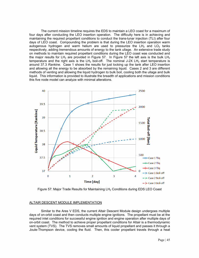
The current mission timeline requires the EDS to maintain a LEO coast for a maximum of four days after conducting the LEO insertion operation. The difficulty here is in achieving and maintaining the required propellant conditions to conduct the trans-lunar injection (TLI) after four days of LEO coast. Compounding the problem is that during the LEO insertion operation warm autogenous hydrogen and warm helium are used to pressurize the LH2 and LO2 tanks respectively, adding tremendous amounts of energy to the tank ullage. An extensive trade study on methods to maintain required propellant conditions during the LEO coast was conducted and the major results for LH2 are provided in Figure 57. In Figure 57 the left axis is the bulk LH2temperature and the right axis is the LH2 boil-off. The nominal J-2X LH2 start temperature is around 37.3 Rankine. Case 1 shows the results for just locking up the tank after LEO insertion and allowing all the energy to be absorbed by the remaining liquid. Cases 2 and 3 are different methods of venting and allowing the liquid hydrogen to bulk boil, cooling both the ullage and bulk liquid. This information is provided to illustrate the breadth of applications and mission conditions this five node model can analyze with minimal alterations.
Figure 57: Major Trade Results for Maintaining LH2 Conditions during EDS LEO Coast
ALTAIR DESCENT MODULE IMPLEMENTATION
Similar to the Ares V EDS, the current Altair Descent Module design undergoes multiple days of on-orbit coast and then conducts multiple engine ignitions. The propellant must be at the required inlet conditions for successful engine ignition and engine operation after multiple days of on-orbit coast. The method to achieve proper propellant conditions for Altair is a thermodynamic vent system (TVS). The TVS removes small amounts of liquid propellant and passes it through a Joule-Thompson device, cooling the fluid. Then, this cooler propellant travels through a heat

Page | 46
exchanger and absorbs some heat from the warmer bulk liquid propellant. Finally, this small propellant flow vents overboard, taking with it some of the bulk liquid propellant heat. As an example, Figure 58 shows LH2 temperature during a 24 hour low lunar orbit (LLO) coast. The TVS was set to operate when the bulk liquid temperature exceeded 39 Rankine and would remove energy until the bulk liquid temperature dropped below 38.5 Rankine. This specific example required two cycles of operation during the coast. Figure 59 shows the mass vented overboard by the TVS (mTVSboil) and the total boil-off mass (mboiltot), which is the summation of the TVS vented mass, internal tank evaporation, and internal tank bulk boiling. This illustrates another minor addition to the five node CPPPO model that helps provide important results used to aide further design considerations.
Figure 58: Altair LH2 Temperature during 24 hour LLO Coast
Figure 59: Altair LH2 Boil-off during 24 hour LLO Coast

Page | 47
Another significant Altair issue was differential draining of the four LH2 and four LO2 tanks during engine operation. This could cause sizeable center of gravity shifts if one tank drains faster than the others. Also, the propellant drains at the tank bottoms could become uncovered in the tanks draining faster, causing possible vapor ingestion into the engine. With some significant model additions extensive analysis of Altair multiple tank draining was conducted. Figure 60 is the LO2 mass flow rate leaving all four tanks for the entire LOI operation, engine chill and mainstage. Differences in the pressurization line resistances between the four tanks cause significant differences in tank pressure and propellant mass flow. This version of the model was used to show the sensitivities in differential tank draining to varying pressurization line resistances.
Figure 60: Altair LO2 Mass Flow Rate during LOI
SUMMARY AND CONCLUSIONS
The propellant and pressurization model outlined herein provides a flexible design tool for liquid rocket based missions from launch to in-space operations. The model calculation speed allows for analysis of multiple design iterations with limited model adjustment while maintaining a reasonable level of fidelity when compared to higher accuracy analytic models and available experimental data. The inclusion of evaporation, liquid bulk boiling, and condensation mass transfer calculations provide another level of detail while maintaining sufficient accuracy. The major impetus for developing the CPPPO model was in-space storage of cryogenic propellants for long duration missions and while the model shows reasonable accuracy with Saturn era AS-203 data further experimental data is necessary. Detailed knowledge of heat inputs is also critical to achieving accurate tank condition calculations as evidenced by the validation and uncertainty analysis outlined previously. The CPPPO model has been utilized for numerous design trades for Ares V Core Stage, Ares V EDS, and Altair Lunar Lander and has proven robust over a broad range of vehicles and operating conditions. However, without detailed knowledge of heat inputs and no long duration in-space test data all results require further discussion and insight.

Page | 48
FUTURE WORK
The process of validating the CPPPO model herein with recently calculated CFD results for the Altair Lunar Lander has begun but still requires more analysis and insight. This will not only show further accuracy but will also highlight specific deficiencies in the five node CPPPO model to be cognizant of when compared to three dimensional CFD.
ACKNOWLEDGMENTS
The author would like to thank Skip Urquhart, Mike Martin, and Jay Russell of NASA MSFC ER-22 branch for their continued support during the model development, debugging, and validation. Also, sincere thanks to Bill Pannell and Kendall Brown of NASA MSFC for allowing the time and funding to complete the CPPPO model. Further, thanks to Roy Rice and Paul Munafo of Teledyne Brown Engineering for assistance in outlining and editing this report. Finally, thanks to Ross Armstrong of Teledyne Brown Engineering for his continual support.
REFERENCES
1. NIST Chemistry Webbook. http://webbook.nist.gov/chemistry.2. “Large Liquid Rocket Engine Transient Performance Simulation System, Final Report,”
United Technologies Corporation, Pratt & Whitney, 1991, Contract Number NAS8-36994.3. Ring, Elliot ed., Rocket Propellant and Pressurization Systems, Prentice-Hall Inc.,
Englewood Cliffs, NJ, 1964.4. McAdams, W.H., Heat Transmission, 3rd ed. New York: McGraw-Hill Book company,
1954.5. “Evaluation of AS-203 Low Gravity Orbital Experiment,” Technical Report HSM-R421-67,
13 January 1967, Contract NAS8-4016 Schedule II, Vehicle Systems Integration.6. Bradshaw, RD, “Evaluation and Application of Data from Low Gravity Orbital
Experiment,” Convair Division of General Dynamics, San Diego, CA, 1 April 1970, Contract NAS8-21291.
7. Barsi, S. and Kassemi, M., “Validation of Tank Self-Pressurization Models in Normal Gravity,” NASA Glenn Research Center, Cleveland, OH, AIAA-2007-952.
8. Fox, R.W. and McDonald, A.T., Introduction to Fluid Mechanics, 5th Edition, pp.732-738, John Wiley & Sons, New York, 1998.