Embed Size (px)
Citation preview
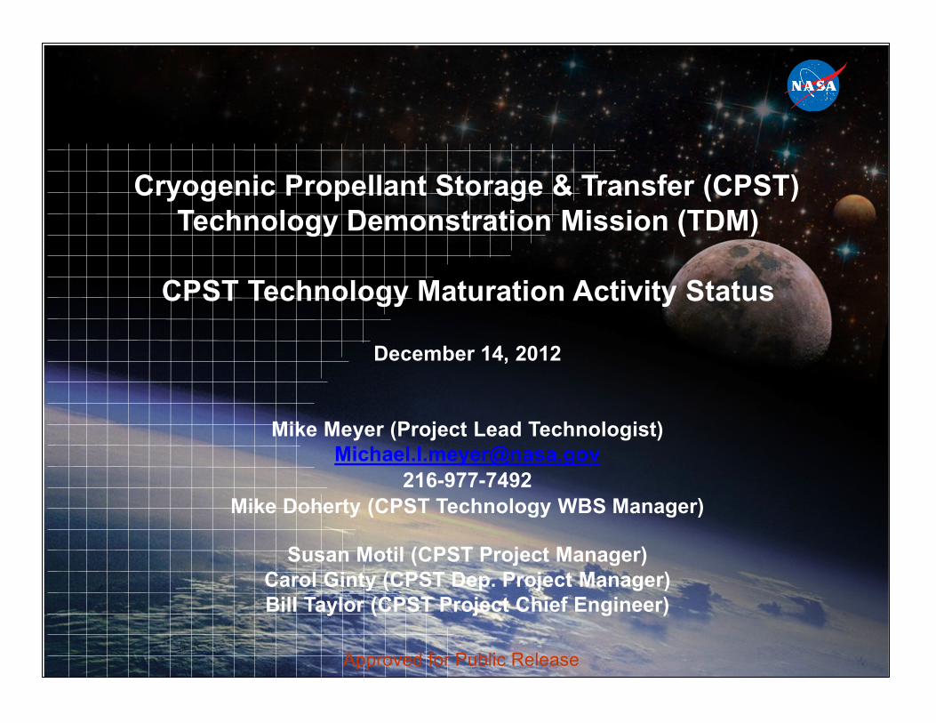
Cryogenic Propellant Storage & Transfer (CPST) Technology Demonstration Mission (TDM)
CPST Technology Maturation Activity Status
December 14, 2012
Mike Meyer (Project Lead Technologist) [email protected]
216-977-7492 Mike Doherty (CPST Technology WBS Manager)
Susan Motil (CPST Project Manager) Carol Ginty (CPST Dep. Project Manager) Bill Taylor (CPST Project Chief Engineer)
Approved for Public Release
a
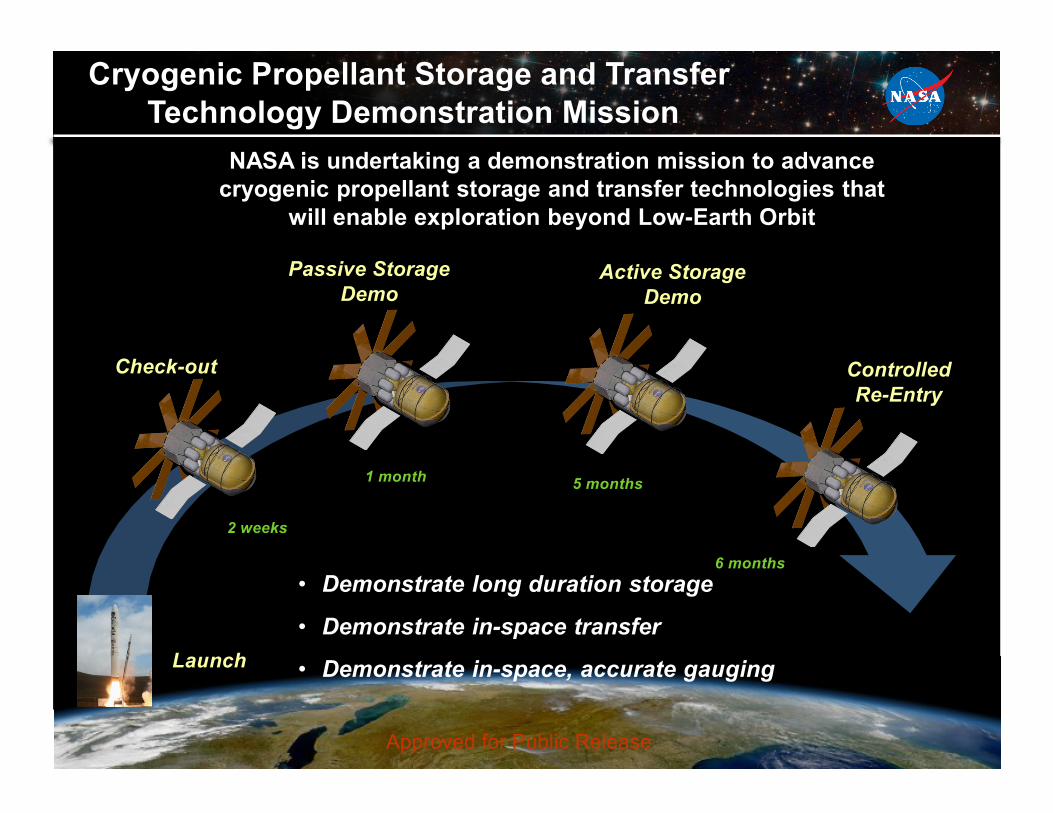
Cryogenic Propellant Storage and Transfer Technology Demonstration Mission
NASA is undertaking a demonstration mission to advance cryogenic propellant storage and transfer technologies that
will enable exploration beyond Low-Earth Orbit
Launch
Check-out
Passive Storage Demo
Active Storage Demo
Controlled Re-Entry
2 weeks
1 month 5 months
6 months • Demonstrate long duration storage
• Demonstrate in-space transfer
• Demonstrate in-space, accurate gauging
Approved for Public Release
5*
CPST Technology Demonstration Overview Te
chno
logi
es
Obj
ectiv
es
Goa
ls
Nee
ds
T
4
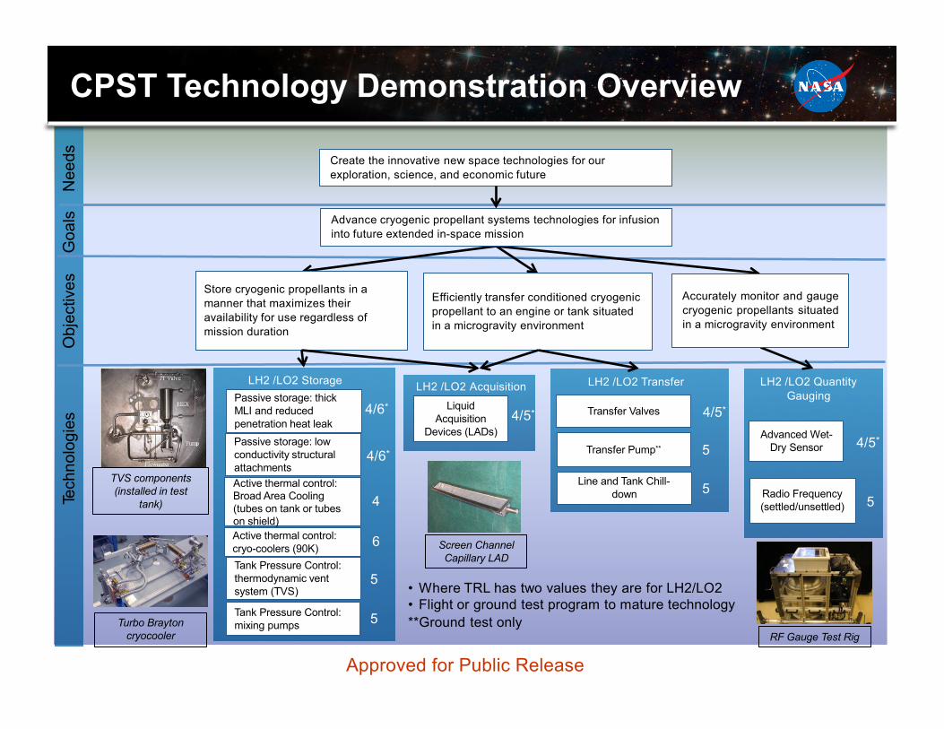
Create the innovative new space technologies for our exploration, science, and economic future
Advance cryogenic propellant systems technologies for infusion into future extended in-space mission
Store cryogenic propellants in a manner that maximizes their availability for use regardless of mission duration
Efficiently transfer conditioned cryogenic propellant to an engine or tank situated in a microgravity environment
Accurately monitor and gauge cryogenic propellants situated in a microgravity environment
TVS components (installed in test
tank)
urbo Brayton cryocooler
LH2 /LO2 Storage Passive storage: thick MLI and reduced penetration heat leak
4/6*
Passive storage: low conductivity structural attachments
/6*
Active thermal control: cryo-coolers (90K)
Active thermal control: Broad Area Cooling (tubes on tank or tubes on shield)
6
4
5
5
Tank Pressure Control: thermodynamic vent system (TVS)
Tank Pressure Control: mixing pumps
LH2 /LO2 Acquisition
Liquid Acquisition
Devices (LADs) 4/
Screen Channel Capillary LAD
• Where TRL has two values they are for LH2/LO2 • Flight or ground test program to mature technology **Ground test only
LH2 /LO2 Transfer
Transfer Valves 4/5*
5 Transfer Pump**
Line and Tank Chill- down 5
LH2 /LO2 Quantity Gauging
Advanced Wet- Dry Sensor 4/5*
Radio Frequency (settled/unsettled) 5
RF Gauge Test Rig
Approved for Public Release
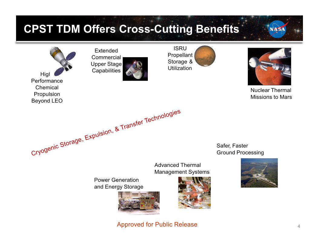
CPST TDM Offers Cross-Cutting Benefits ISRU
Propellant Storage & Utilization
Extended Commercial Upper Stage Capabilities High-
Performance Chemical
Propulsion Beyond LEO
Nuclear Thermal Missions to Mars
Power Generation and Energy Storage
Advanced Thermal Management Systems
Safer, Faster Ground Processing
Approved for Public Release 4
Background on CPST Technology Activities
Three categories of testing are discussed in this package:
• Technology Maturation: Raising the TRL of technologies planned for the flight demonstration to reduce the flight development risk.
• Integrated Ground Testing: Testing multiple technologies at once to identify unexpected interactions that might impact performance.
• Ground Demonstration: Demonstration of technology/capability on the ground in parallel with the flight demonstration to to achieve broader (more comprehensive) demonstration scope at lower cost.
In addition, development and validation of analytical tools/modeling focused on CFM technology and capability are a critical aspect the CPST TDM.
Approved for Public Release 5
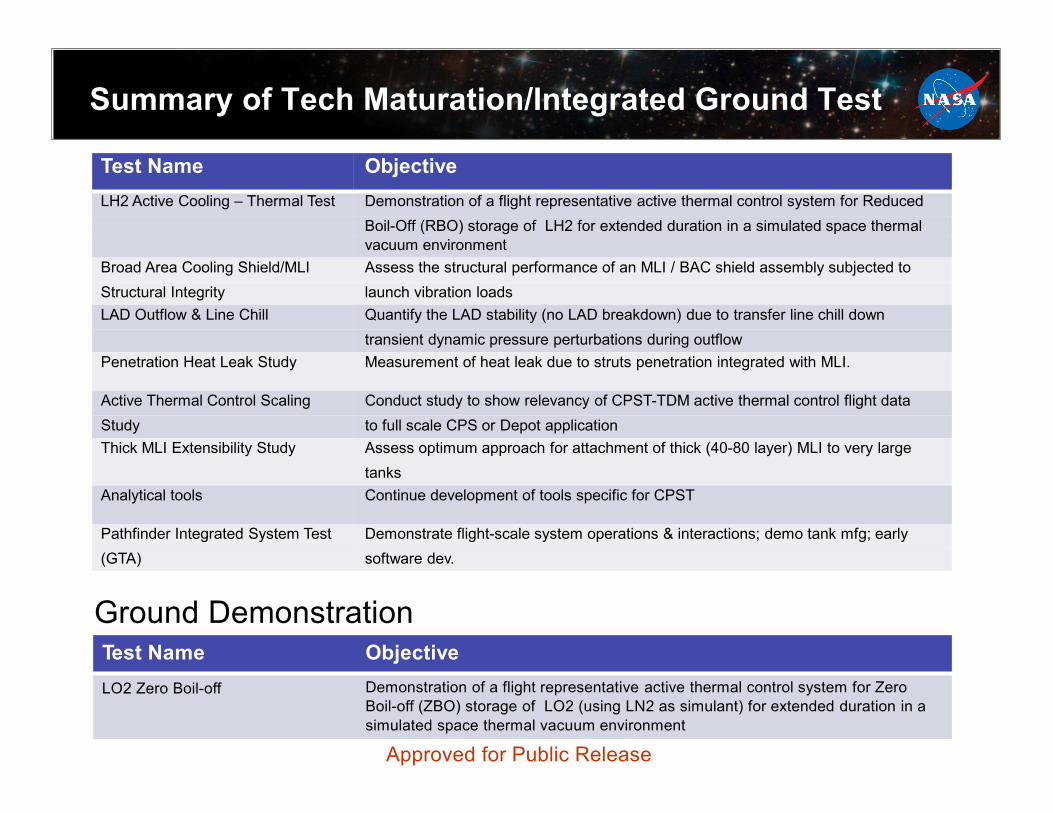
Summary of Tech Maturation/Integrated Ground Test
Test Name Objective LH2 Active Cooling – Thermal Test Demonstration of a flight representative active thermal control system for Reduced
Boil-Off (RBO) storage of LH2 for extended duration in a simulated space thermal vacuum environment
Broad Area Cooling Shield/MLI Assess the structural performance of an MLI / BAC shield assembly subjected to Structural Integrity launch vibration loads LAD Outflow & Line Chill Quantify the LAD stability (no LAD breakdown) due to transfer line chill down
transient dynamic pressure perturbations during outflow Penetration Heat Leak Study Measurement of heat leak due to struts penetration integrated with MLI.
Active Thermal Control Scaling Conduct study to show relevancy of CPST-TDM active thermal control flight data Study to full scale CPS or Depot application Thick MLI Extensibility Study Assess optimum approach for attachment of thick (40-80 layer) MLI to very large
tanks Analytical tools Continue development of tools specific for CPST
Pathfinder Integrated System Test Demonstrate flight-scale system operations & interactions; demo tank mfg; early (GTA) software dev.
Ground Demonstration
Test Name Objective LO2 Zero Boil-off Demonstration of a flight representative active thermal control system for Zero
Boil-off (ZBO) storage of LO2 (using LN2 as simulant) for extended duration in a simulated space thermal vacuum environment
Approved for Public Release
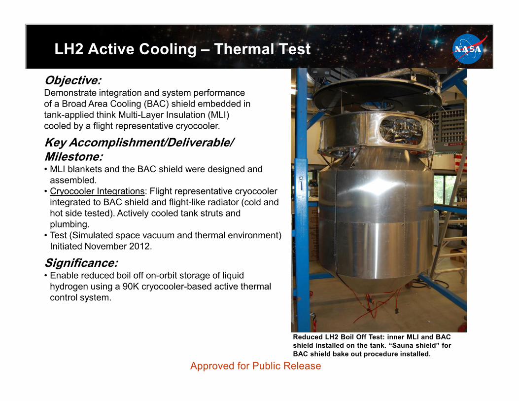
LH2 Active Cooling – Thermal Test
Objective: Demonstrate integration and system performance of a Broad Area Cooling (BAC) shield embedded in tank-applied think Multi-Layer Insulation (MLI) cooled by a flight representative cryocooler.
Key Accomplishment/Deliverable/ Milestone: • MLI blankets and the BAC shield were designed and
assembled. • Cryocooler Integrations: Flight representative cryocooler
integrated to BAC shield and flight-like radiator (cold and hot side tested). Actively cooled tank struts and plumbing.
• Test (Simulated space vacuum and thermal environment) Initiated November 2012.
Significance: • Enable reduced boil off on-orbit storage of liquid
hydrogen using a 90K cryocooler-based active thermal control system.
Reduced LH2 Boil Off Test: inner MLI and BAC shield installed on the tank. “Sauna shield” for BAC shield bake out procedure installed.
Approved for Public Release
MLI/BAC Shield Structural Integrity Test
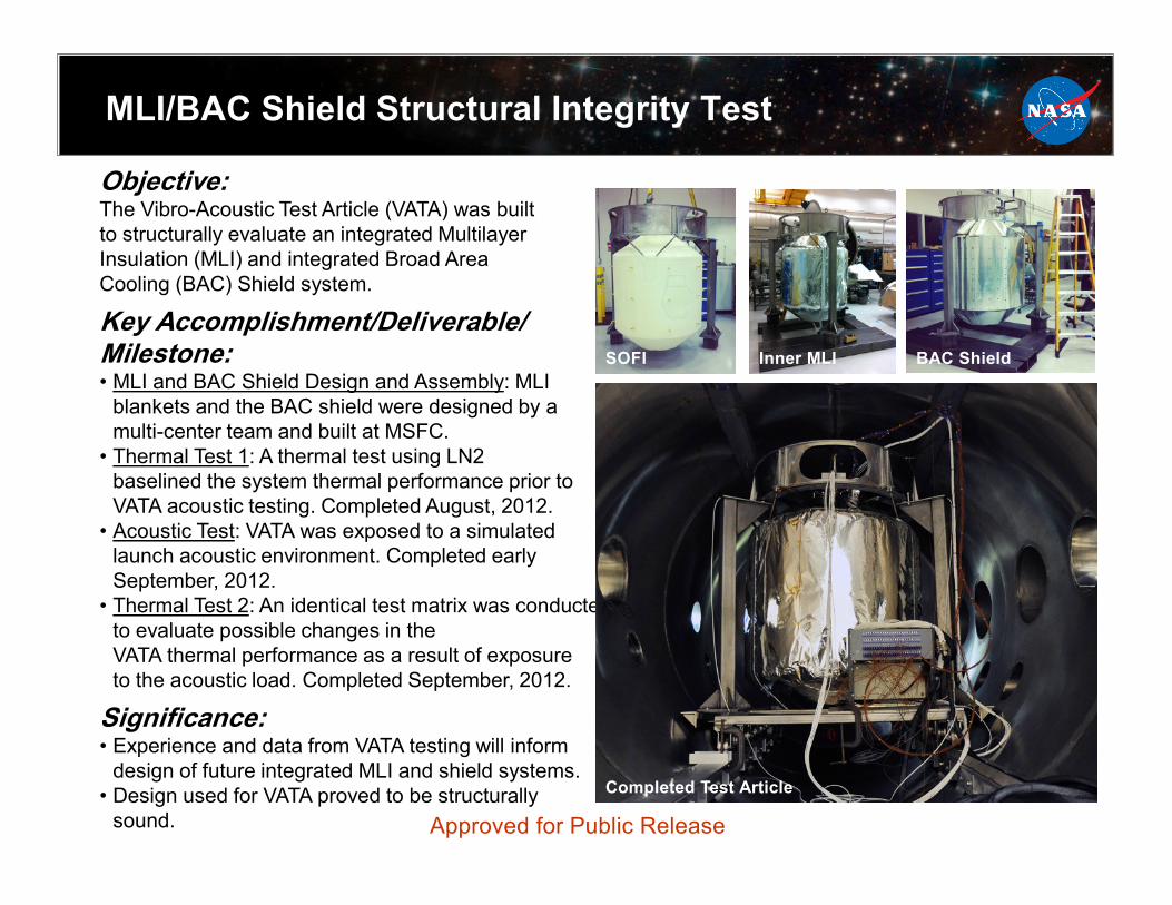
Objective: The Vibro-Acoustic Test Article (VATA) was built to structurally evaluate an integrated Multilayer Insulation (MLI) and integrated Broad Area Cooling (BAC) Shield system.
Key Accomplishment/Deliverable/ Milestone: • MLI and BAC Shield Design and Assembly: MLI
blankets and the BAC shield were designed by a multi-center team and built at MSFC.
• Thermal Test 1: A thermal test using LN2 baselined the system thermal performance prior to VATA acoustic testing. Completed August, 2012.
• Acoustic Test: VATA was exposed to a simulated launch acoustic environment. Completed early September, 2012.
• Thermal Test 2: An identical test matrix was conducted to evaluate possible changes in the VATA thermal performance as a result of exposure to the acoustic load. Completed September, 2012.
Significance: • Experience and data from VATA testing will inform
design of future integrated MLI and shield systems. • Design used for VATA proved to be structurally
sound.
Approved for Public Release
SOFI Inner MLI BAC Shield
Completed Test Article
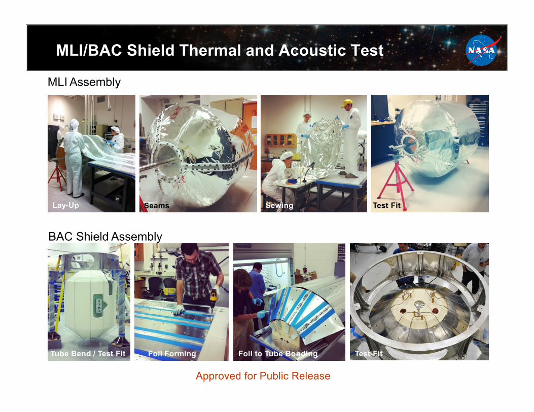
MLI/BAC Shield Thermal and Acoustic Test
MLI Assembly
Lay-Up Seams
Sewing Test Fit
BAC Shield Assembly
Tube Bend / Test Fit Foil Forming Foil to Tube Bonding Test Fit
Approved for Public Release
LAD Outflow & Line Chilldown
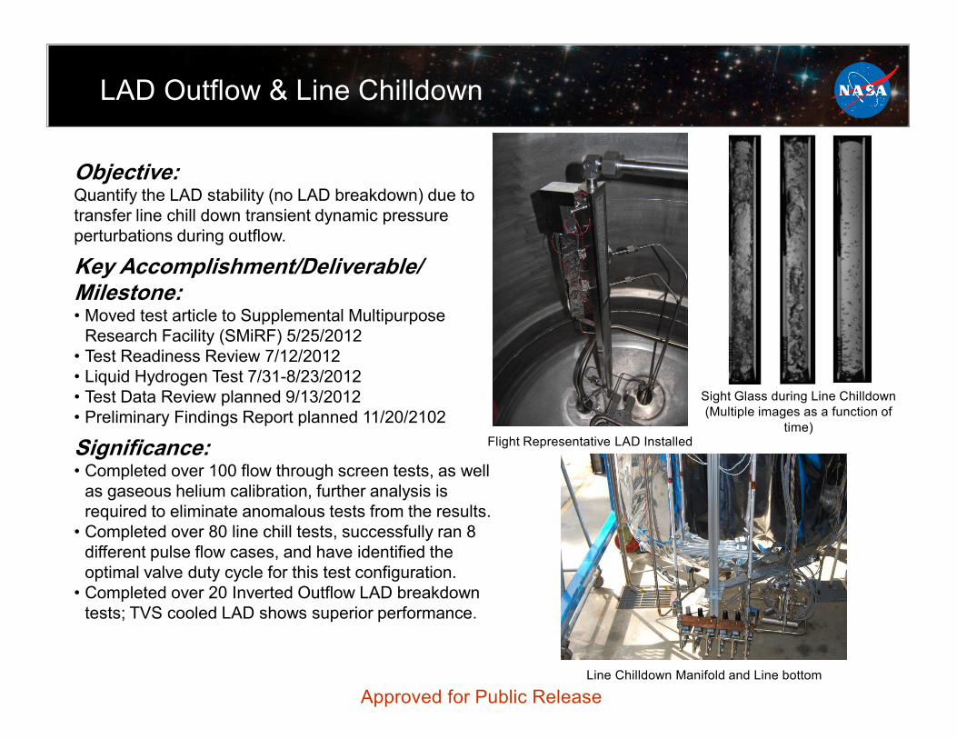
Objective: Quantify the LAD stability (no LAD breakdown) due to transfer line chill down transient dynamic pressure perturbations during outflow.
Key Accomplishment/Deliverable/ Milestone: • Moved test article to Supplemental Multipurpose
Research Facility (SMiRF) 5/25/2012 • Test Readiness Review 7/12/2012 • Liquid Hydrogen Test 7/31-8/23/2012 • Test Data Review planned 9/13/2012 • Preliminary Findings Report planned 11/20/2102
Significance: • Completed over 100 flow through screen tests, as well
as gaseous helium calibration, further analysis is required to eliminate anomalous tests from the results.
• Completed over 80 line chill tests, successfully ran 8 different pulse flow cases, and have identified the optimal valve duty cycle for this test configuration.
• Completed over 20 Inverted Outflow LAD breakdown tests; TVS cooled LAD shows superior performance.
Sight Glass during Line Chilldown (Multiple images as a function of
time) Flight Representative LAD Installed
Line Chilldown Manifold and Line bottom
Approved for Public Release
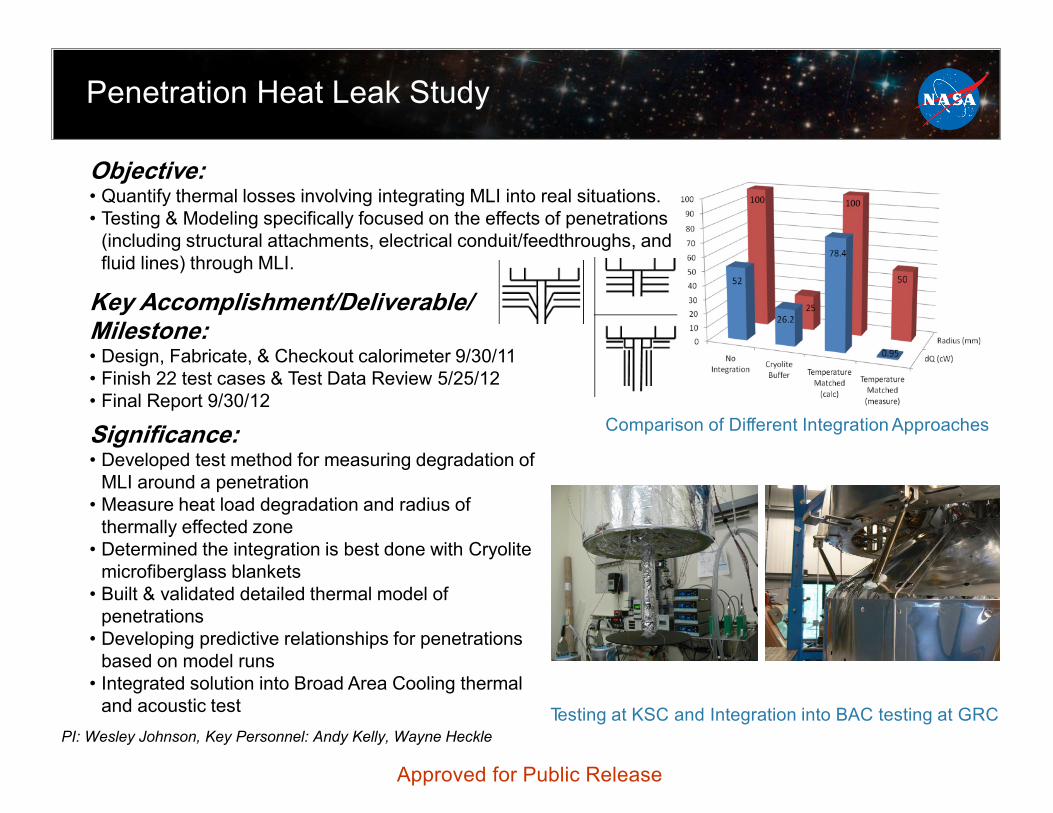
Penetration Heat Leak Study
PI: Wesley Johnson, Key Personnel: Andy Kelly, Wayne Heckle
Key Accomplishment/Deliverable/ Milestone: • Design, Fabricate, & Checkout calorimeter 9/30/11 • Finish 22 test cases & Test Data Review 5/25/12 • Final Report 9/30/12
Significance: • Developed test method for measuring degradation of
MLI around a penetration • Measure heat load degradation and radius of
thermally effected zone • Determined the integration is best done with Cryolite
microfiberglass blankets • Built & validated detailed thermal model of
penetrations • Developing predictive relationships for penetrations
based on model runs • Integrated solution into Broad Area Cooling thermal
and acoustic test
Objective: • Quantify thermal losses involving integrating MLI into real situations. • Testing & Modeling specifically focused on the effects of penetrations
(including structural attachments, electrical conduit/feedthroughs, and fluid lines) through MLI.
Comparison of Different Integration Approaches
Testing at KSC and Integration into BAC testing at GRC
Approved for Public Release
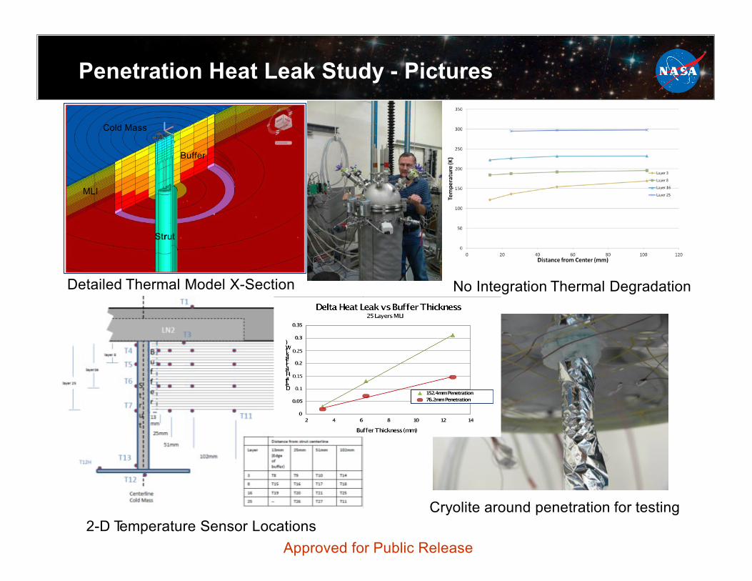
Penetration Heat Leak Study - Pictures
Cold Mass
MLI
Buffer
Strut
Detailed Thermal Model X-Section No Integration Thermal Degradation
Cryolite around penetration for testing 2-D Temperature Sensor Locations
Approved for Public Release
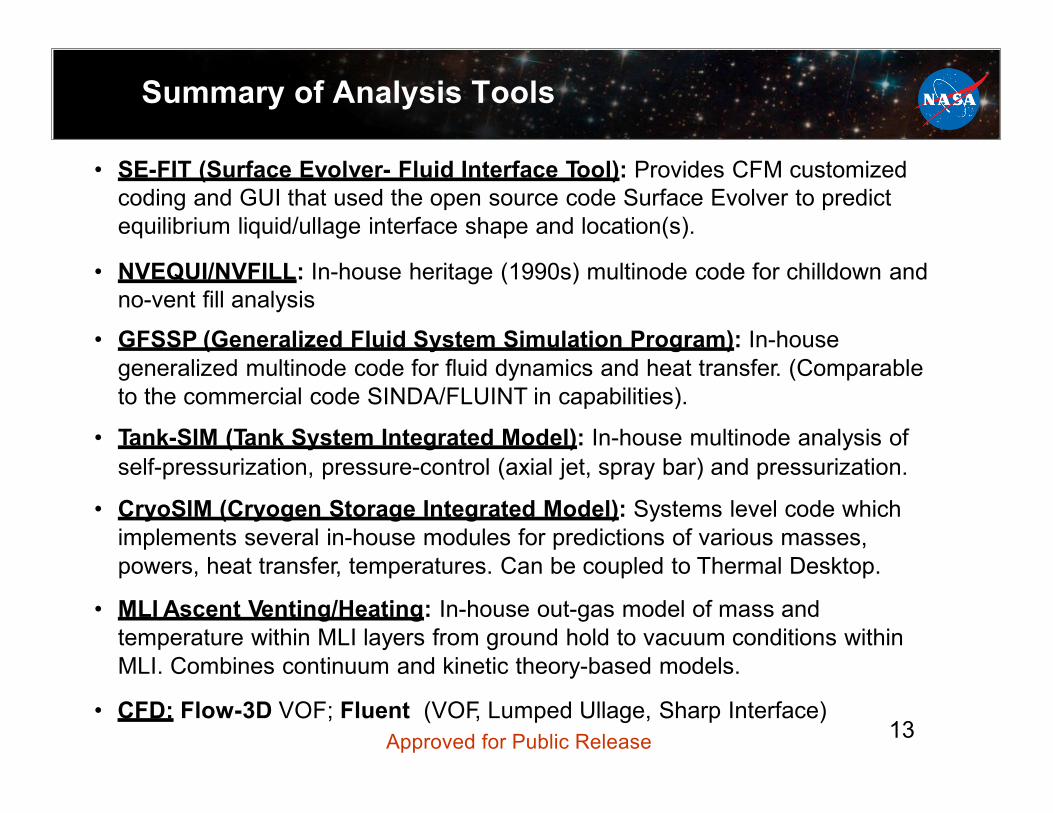
Summary of Analysis Tools
• SE-FIT (Surface Evolver- Fluid Interface Tool): Provides CFM customized coding and GUI that used the open source code Surface Evolver to predict equilibrium liquid/ullage interface shape and location(s).
• NVEQUI/NVFILL: In-house heritage (1990s) multinode code for chilldown and no-vent fill analysis
• GFSSP (Generalized Fluid System Simulation Program): In-house generalized multinode code for fluid dynamics and heat transfer. (Comparable to the commercial code SINDA/FLUINT in capabilities).
• Tank-SIM (Tank System Integrated Model): In-house multinode analysis of self-pressurization, pressure-control (axial jet, spray bar) and pressurization.
• CryoSIM (Cryogen Storage Integrated Model): Systems level code which implements several in-house modules for predictions of various masses, powers, heat transfer, temperatures. Can be coupled to Thermal Desktop.
• MLI Ascent Venting/Heating: In-house out-gas model of mass and temperature within MLI layers from ground hold to vacuum conditions within MLI. Combines continuum and kinetic theory-based models.
• CFD: Flow-3D VOF; Fluent (VOF, Lumped Ullage, Sharp Interface) Approved for Public Release 13
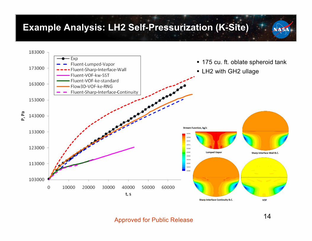
Example Analysis: LH2 Self-Pressurization (K-Site)
175 cu. ft. oblate spheroid tank LH2 with GH2 ullage
Approved for Public Release 14
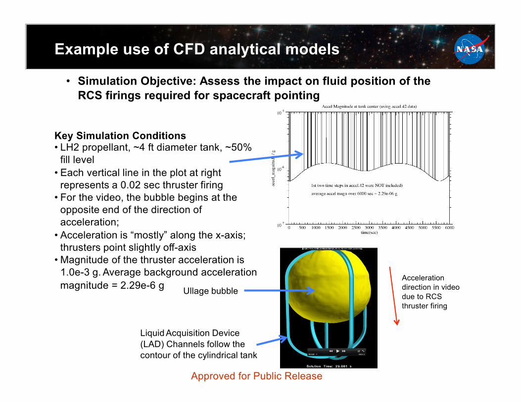
Example use of CFD analytical models
• Simulation Objective: Assess the impact on fluid position of the RCS firings required for spacecraft pointing
Key Simulation Conditions • LH2 propellant, ~4 ft diameter tank, ~50%
fill level • Each vertical line in the plot at right
represents a 0.02 sec thruster firing • For the video, the bubble begins at the
opposite end of the direction of acceleration; • Acceleration is “mostly” along the x-axis;
thrusters point slightly off-axis • Magnitude of the thruster acceleration is
1.0e-3 g. Average background acceleration magnitude = 2.29e-6 g Ullage bubble
Liquid Acquisition Device (LAD) Channels follow the contour of the cylindrical tank
Acceleration direction in video due to RCS thruster firing
Approved for Public Release
CPST Continuing Activities
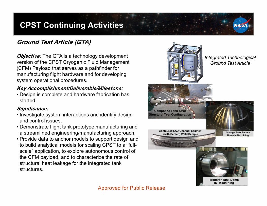
Ground Test Article (GTA) Objective: The GTA is a technology development version of the CPST Cryogenic Fluid Management (CFM) Payload that serves as a pathfinder for manufacturing flight hardware and for developing system operational procedures. Key Accomplishment/Deliverable/Milestone: • Design is complete and hardware fabrication has
started. Significance: • Investigate system interactions and identify design
and control issues. • Demonstrate flight tank prototype manufacturing and
a streamlined engineering/manufacturing approach. • Provide data to anchor models to support design and
to build analytical models for scaling CPST to a “full-scale” application, to explore autonomous control of the CFM payload, and to characterize the rate of structural heat leakage for the integrated tank structures.
Integrated Technological Ground Test Article
Composite Tank Strut Structural Test Configuration
Storage Tank Bottom Dome in Machining
Contoured LAD Channel Segment (with Screen) Weld Sample
Transfer Tank Dome ID Machining
Approved for Public Release
CPST FY12 WBS 4.0 Technology Maturation Accomplishments
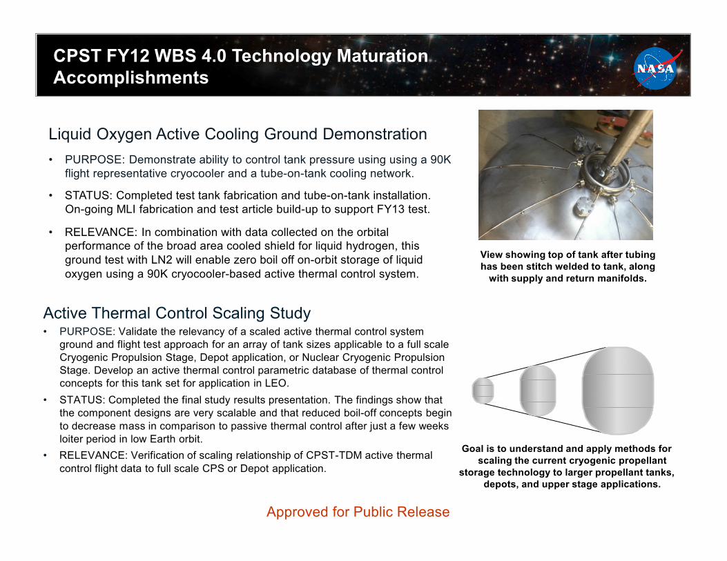
Liquid Oxygen Active Cooling Ground Demonstration • PURPOSE: Demonstrate ability to control tank pressure using using a 90K
flight representative cryocooler and a tube-on-tank cooling network.
• STATUS: Completed test tank fabrication and tube-on-tank installation. On-going MLI fabrication and test article build-up to support FY13 test.
• RELEVANCE: In combination with data collected on the orbital
performance of the broad area cooled shield for liquid hydrogen, this ground test with LN2 will enable zero boil off on-orbit storage of liquid oxygen using a 90K cryocooler-based active thermal control system.
View showing top of tank after tubing has been stitch welded to tank, along
with supply and return manifolds.
Active Thermal Control Scaling Study • PURPOSE: Validate the relevancy of a scaled active thermal control system
ground and flight test approach for an array of tank sizes applicable to a full scale Cryogenic Propulsion Stage, Depot application, or Nuclear Cryogenic Propulsion Stage. Develop an active thermal control parametric database of thermal control concepts for this tank set for application in LEO.
• STATUS: Completed the final study results presentation. The findings show that the component designs are very scalable and that reduced boil-off concepts begin to decrease mass in comparison to passive thermal control after just a few weeks loiter period in low Earth orbit.
• RELEVANCE: Verification of scaling relationship of CPST-TDM active thermal control flight data to full scale CPS or Depot application.
Goal is to understand and apply methods for scaling the current cryogenic propellant
storage technology to larger propellant tanks, depots, and upper stage applications.
Approved for Public Release

Technical Status
Related Activities:
• CPST • RF Mass Gauging Advanced Development:
• OCT Game Changing/CPST: • Self Supporting MLI
Approved for Public Release 18
Radio Frequency Mass Gauge
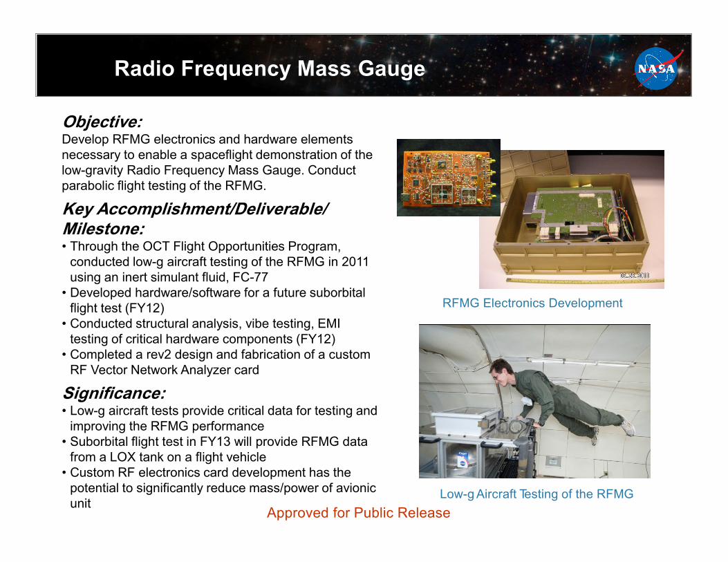
Objective: Develop RFMG electronics and hardware elements necessary to enable a spaceflight demonstration of the low-gravity Radio Frequency Mass Gauge. Conduct parabolic flight testing of the RFMG.
Key Accomplishment/Deliverable/ Milestone: • Through the OCT Flight Opportunities Program,
conducted low-g aircraft testing of the RFMG in 2011 using an inert simulant fluid, FC-77
• Developed hardware/software for a future suborbital flight test (FY12)
• Conducted structural analysis, vibe testing, EMI testing of critical hardware components (FY12)
• Completed a rev2 design and fabrication of a custom RF Vector Network Analyzer card
Significance: • Low-g aircraft tests provide critical data for testing and
improving the RFMG performance • Suborbital flight test in FY13 will provide RFMG data
from a LOX tank on a flight vehicle • Custom RF electronics card development has the
potential to significantly reduce mass/power of avionic unit
RFMG Electronics Development
Low-g Aircraft Testing of the RFMG Approved for Public Release

Self-Supporting MLI (SSMLI)
Flat-plate calorimeter for insulation penetration performance tests
Background: This project is led by STP’s Game Changing Program Office with some co-funding support from CPST.
Objective: The objective of this project is to raise the Technology Readiness Level (TRL) of self-supporting high performance MLI. After all of the risks are successfully mitigated and the TRL is raised to TRL five, the technology is targeted to be infused into the Cryogenic Propellant Storage and Transfer (CPST) project. Key Accomplishment/Deliverable/Milestone: • Procure SSMLI coupons and blankets • Coupon Level testing
• LN2 calorimeter performance testing • Insulation penetration performance testing • 20-90 K temperature performance testing • Acoustic testing
• Tank-applied performance testing (with integrated active cooling shield) • Structural integrity test (acoustic environment) • Thermal performance with LH2 (passive and 90 K active cooling)
• Data review presentation • All milestones to be completed by May 2013
Significance: • Enable improved performance integrated passive and active thermal control
system for cryogenic propellant tanks. • Enable improved extensibility for high performance insulation to very large
cryogenic propellant tanks.
Test Article for Tank-applied thermal testing
Approved for Public Release