Embed Size (px)
Citation preview
David PlachtaGlenn Research Center, Cleveland, Ohio
Peter KittelAmes Research Center, Moffett Field, California
An Updated Zero Boil-Off CryogenicPropellant Storage Analysis Appliedto Upper Stages or Depots in anLEO Environment
NASA/TM—2003-211691
June 2003
AIAA–2002–3589
https://ntrs.nasa.gov/search.jsp?R=20030067928 2018-09-14T02:26:11+00:00Z
The NASA STI Program Office . . . in Profile
Since its founding, NASA has been dedicated tothe advancement of aeronautics and spacescience. The NASA Scientific and TechnicalInformation (STI) Program Office plays a key partin helping NASA maintain this important role.
The NASA STI Program Office is operated byLangley Research Center, the Lead Center forNASA’s scientific and technical information. TheNASA STI Program Office provides access to theNASA STI Database, the largest collection ofaeronautical and space science STI in the world.The Program Office is also NASA’s institutionalmechanism for disseminating the results of itsresearch and development activities. These resultsare published by NASA in the NASA STI ReportSeries, which includes the following report types:
• TECHNICAL PUBLICATION. Reports ofcompleted research or a major significantphase of research that present the results ofNASA programs and include extensive dataor theoretical analysis. Includes compilationsof significant scientific and technical data andinformation deemed to be of continuingreference value. NASA’s counterpart of peer-reviewed formal professional papers buthas less stringent limitations on manuscriptlength and extent of graphic presentations.
• TECHNICAL MEMORANDUM. Scientificand technical findings that are preliminary orof specialized interest, e.g., quick releasereports, working papers, and bibliographiesthat contain minimal annotation. Does notcontain extensive analysis.
• CONTRACTOR REPORT. Scientific andtechnical findings by NASA-sponsoredcontractors and grantees.
• CONFERENCE PUBLICATION. Collectedpapers from scientific and technicalconferences, symposia, seminars, or othermeetings sponsored or cosponsored byNASA.
• SPECIAL PUBLICATION. Scientific,technical, or historical information fromNASA programs, projects, and missions,often concerned with subjects havingsubstantial public interest.
• TECHNICAL TRANSLATION. English-language translations of foreign scientificand technical material pertinent to NASA’smission.
Specialized services that complement the STIProgram Office’s diverse offerings includecreating custom thesauri, building customizeddatabases, organizing and publishing researchresults . . . even providing videos.
For more information about the NASA STIProgram Office, see the following:
• Access the NASA STI Program Home Pageat http://www.sti.nasa.gov
• E-mail your question via the Internet [email protected]
• Fax your question to the NASA AccessHelp Desk at 301–621–0134
• Telephone the NASA Access Help Desk at301–621–0390
• Write to: NASA Access Help Desk NASA Center for AeroSpace Information 7121 Standard Drive Hanover, MD 21076
David PlachtaGlenn Research Center, Cleveland, Ohio
Peter KittelAmes Research Center, Moffett Field, California
An Updated Zero Boil-Off CryogenicPropellant Storage Analysis Appliedto Upper Stages or Depots in anLEO Environment
NASA/TM—2003-211691
June 2003
National Aeronautics andSpace Administration
Glenn Research Center
Prepared for the38th Joint Propulsion Conference and Exhibitcosponsored by AIAA, ASME, SAE, and ASEEIndianapolis, Indiana, July 7–10, 2002
AIAA–2002–3589

Acknowledgments
The authors want to acknowledge Robert Christie and Dale Robinson of ZIN Technologies, Inc.for their design integration work on the Protoflight ZBO Development Test Article,
and Ken Mellott and Steve Geng of NASA GRC for their radiator analysis.
Available from
NASA Center for Aerospace Information7121 Standard DriveHanover, MD 21076
National Technical Information Service5285 Port Royal RoadSpringfield, VA 22100
This report is a formal draft or workingpaper, intended to solicit comments and
ideas from a technical peer group.
This report contains preliminaryfindings, subject to revision as
analysis proceeds.
Available electronically at http://gltrs.grc.nasa.gov
NASA/TM�2003-211691 1
AN UPDATED ZERO BOIL-OFF CRYOGENIC PROPELLANT STORAGE ANALYSIS APPLIED TO UPPER STAGES OR DEPOTS IN AN LEO ENVIRONMENT
David Plachta
National Aeronautics and Space Administration Glenn Research Center Cleveland, Ohio 44135
Peter Kittel
National Aeronautics and Space Administration Ames Research Center
Moffet Field, California 94035
Abstract Previous efforts have shown the analytical benefits of zero boil-off (ZBO) cryogenic propellant storage in launch vehicle upper stages of Mars transfer vehicles for conceptual Mars Missions. However, recent NASA mission investigations have looked at a different and broad array of missions, including a variety of orbit transfer vehicle (OTV) propulsion concepts, some requiring cryogenic storage. For many of the missions, this vehicle will remain for long periods (greater than one week) in low earth orbit (LEO), a relatively warm thermal environment. Under this environment, and with an array of tank sizes and propellants, the performance of a ZBO cryogenic storage system is predicted and compared with a traditional, passive-only storage concept. The results show mass savings over traditional, passive- only cryogenic storage when mission durations are less than one week in LEO for oxygen, two weeks for methane, and roughly 2 months for LH2. Cryogenic xenon saves mass over passive storage almost immediately.
Introduction
NASA has redirected the Integrated In-Space Transportation Program (IISTP) from Code R management to Code S; accordingly, the propulsion elements under development are aligned with science and exploration mission concepts. Several propulsion concepts being studied for these missions could involve cryogenic propellant storage; specifically, advanced chemical, nuclear bi-modal, solar thermal, and perhaps solar electric propulsion, particularly if it is combined with an advanced chemical propulsion assist. In addition to these concepts for IISTP, a propellant depot called the Hybrid Propulsion Module (HPM) led by NASA Langley Research Center, includes cryogenic propellants. These concepts would all involve orbit transfer from LEO, some to higher earth orbits and most to other planets or destinations. The duration of the storage for all of these concepts varies from minutes to years; the
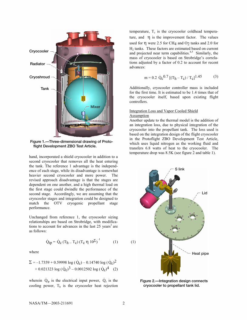
purpose of this paper is to estimate the durations where the ZBO storage approach begins to reduce mass of the OTV. This estimation is based on scaling parameters determined from testing as well as analysis and design. The ZBO design work referenced is from a Protoflight ZBO Development Test Article (configu-ration shown in figure 1), which includes a flight cryocooler integrated with a propellant tank and a radiator, in a LEO simulated thermal environment. The designs and estimations are guides for propulsion and mission design engineers in their evaluations and trade-studies involving cryogenic propellant usage. Besides helping them, this paper advances several details of the ZBO storage concept from previous studies.1,2 First, a detailed cryocooler integration design is shown and associated temperature drops are included, as they represent losses that require the cryocooler to operate at a lower temperature. Secondly, a tank mixer has been added to force flow across the heat exchanger coupled to the cryocooler. In addition, a radiator and associated thermal analysis is incorporated to reject the heat from the cryocooler. Finally, a look into the appropriate number of MLI layers for a ZBO tank is described.
Thermal Model The following discussions on the analysis form the basis of the thermal model used in the analysis. Several parts are repeated from reference 1 for clarity, but the bulk of the work is based on additional research and design. Cryocooler Model The cryocooler model used is updated from refer-ence 1. While the hydrogen cryocooler is again modeled using two cryocoolers (for simplicity), in this approach the first cryocooler is used to reduce the temperature of a tank shield to a typical intermediate value of a first stage of a two-stage cooler; the second cryocooler removes the remaining heat that enters the tank through that shield. Reference 1, on the other
NASA/TM�2003-211691 2
Figure 1.—Three-dimensional drawing of Proto- flight Development ZBO Test Article.
Mixer
Tank
Cryocooler
Radiator
Cryoshroud
hand, incorporated a shield cryocooler in addition to a second cryocooler that removes all the heat entering the tank. The reference 1 advantage is the independ-ence of each stage, while its disadvantage is somewhat heavier second cryocooler and more power. The revised approach disadvantage is that the stages are dependent on one another, and a high thermal load on the first stage could dwindle the performance of the second stage. Accordingly, we are assuming that the cryocooler stages and integration could be designed to match the OTV cryogenic propellant stage performance. Unchanged from reference 1, the cryocooler sizing relationships are based on Strobridge, with modifica-tions to account for advances in the last 25 years3 are as follows:
Q! ip = Q! c (Th � Tc) (Tc η 10Σ)
�1 (1) (1)
where Σ = �1.7359 + 0.59998 log ( Q! c) � 0.14740 log ( Q! c)2
+ 0.021323 log ( Q! c)3 � 0.0012502 log ( Q! c)4 (2) wherein Q! ip is the electrical input power, Q! c is the cooling power, Th is the cryocooler heat rejection
temperature, Tc is the cryocooler coldhead tempera-ture, and η is the improvement factor. The values used for η were 2.5 for CH4 and O2 tanks and 2.0 for H2 tanks. These factors are estimated based on current and projected near term capabilities.4,5 Similarly, the mass of cryocooler is based on Strobridge�s correla-tions adjusted by a factor of 0.2 to account for recent advances: m = 0.2 Q! c0.7 [(Th � Tc) / Tc]1.45 (3)
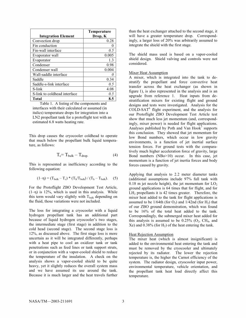
Additionally, cryocooler controller mass is included for the first time. It is estimated to be 1.4 times that of the cryocooler itself, based upon existing flight controllers. Integration Loss and Vapor Cooled Shield Assumption Another update to the thermal model is the addition of an integration loss, due to physical integration of the cryocooler into the propellant tank. The loss used is based on the integration design of the flight cryocooler in the Protoflight ZBO Development Test Article, which uses liquid nitrogen as the working fluid and transfers 6.8 watts of heat to the cryocooler. The temperature drop was 8.5K (see figure 2 and table 1).
Figure 2.—Integration design connects cryocooler to propellant tank lid.
Lid
S link
Heat pipe
NASA/TM�2003-211691 3
Integration Element Temperature
Drop, K Convection drop 0.28 Fin conduction 0 Fin-wall interface 0.5 Evaporator wall 0.005 Evaporator 1.3 Condenser 0.98 Condenser wall 0.004 Wall-saddle interface 0 Saddle 0.34 Saddle-s-link interface 0.5 S-link 4.08 S-link to coldhead interface 0.5 Total 8.5
Table 1. A listing of the components and interfaces with their calculated or assumed (in italics) temperature drops for integration into a LN2 propellant tank for a protoflight test with an estimated 6.8 watts heating rate.
This drop causes the cryocooler coldhead to operate that much below the propellant bulk liquid tempera-ture, as follows: Tc= Tbulk � Tdrop. (4) This is represented as inefficiency according to the following equation:
(1�η) = (Tbulk � Tc) * (Th/Tbulk) / (Th � Tbulk). (5)
For the Protoflight ZBO Development Test Article, (1�η) is 12%, which is used in this analysis. While this term would vary slightly with Tbulk depending on the fluid, those variations were not included. The loss for integrating a cryocooler with a liquid hydrogen propellant tank has an additional part because of liquid hydrogen cryocooler�s two stages, the intermediate stage (first stage) in addition to the cold head (second stage). The second stage loss is 12%, as discussed above. The first stage loss is more uncertain as it will be integrated differently, perhaps with a heat pipe to cool an oxidizer tank or tank penetrations such as feed lines or tank support struts, or in conjunction with a vapor-cooled shield to reduce the temperature of the insulation. A check on the analysis shows a vapor-cooled shield to be quite heavy, yet it slightly reduces the overall system mass and we have assumed its use around the tank. Because it is much larger and the heat travels further
than the heat exchanger attached to the second stage, it will have a greater temperature drop. Correspond-ingly, a larger loss of 20% was arbitrarily assumed to integrate the shield with the first stage. The shield mass used is based on a vapor-cooled shield design. Shield valving and controls were not considered. Mixer Heat Assumption A mixer, which is integrated into the tank to de-stratify the propellant and force convective heat transfer across the heat exchanger (as shown in figure 1), is also represented in the analysis and is an upgrade from reference 1. Heat inputs from de-stratification mixers for existing flight and ground designs and tests were investigated. Analysis for the COLD-SAT6 flight experiment, and the analysis for our Protoflight ZBO Development Test Article test show that much less jet momentum (and, correspond-ingly, mixer power) is needed for flight applications. Analyses published by Poth and Van Hook7 supports this conclusion. They showed that jet momentum for low Bond numbers, which occur in low gravity environments, is a function of jet inertial surface tension forces. For ground tests with the compara-tively much higher acceleration force of gravity, large Bond numbers (NBo>10) occur. In this case, jet momentum is a function of jet inertia forces and body forces caused by gravity. Applying that analysis to 2.2 meter diameter tanks (additional assumptions include 97% full tank with 0.18 m jet nozzle height), the jet momentum for LO2 ground applications is 64 times that for flight, and for LH2 propellants it is 42 times greater. Therefore, the mixer heat added to the tank for flight applications is assumed to be 1/64th (for O2) and 1/42nd (for H2) that of our ZBO ground demonstration, which was found to be 16% of the total heat added to the tank. Correspondingly, the submerged mixer heat added for this analysis is assumed to be 0.25% (O2, CH4, and Xe) and 0.38% (for H2) of the heat entering the tank. Heat Rejection Assumption The mixer heat (which is almost insignificant) is added to the environmental heat entering the tank and must be removed by the cryocooler and ultimately rejected by its radiator. The lower the rejection temperature is, the higher the Carnot efficiency of the system. The radiator design, cryocooler input power, environmental temperature, vehicle orientation, and the propellant tank heat load directly affect this temperature.
NASA/TM�2003-211691 4
For the Protoflight ZBO Development Test Article, an ANSYS thermal model found the heat rejection temperature to be 50K above the environmental temperature for the radiator design used. Flight radiator designs will be more efficient and, according to the cryocooler manufacturer,8 this design tempera-ture could be improved for flight to roughly 30K, which was used in this analysis. MLI Assumption Another variation from reference 1 is that the number of MLI layers used was eliminated as a variable. This was done to present the results more simply; also, by using a spreadsheet analysis it was possible to narrow in on the appropriate number of layers for each propellant studied. This was found by adding up the predicted passive and ZBO thermal storage mass, that is, the tank, insulation, propellant, and boil-off mass for the passive case and the tank, insulation, propel-lant, solar array, and radiator mass for the ZBO case for a given number of MLI layers, then vary the quantity of layers and narrow in on the lowest mass results at the point where the passive and ZBO masses were equal. This was done for the average tank diameter used for each propellant. For the LH2 case, the layers were divided up such that 2/3rds (or 30 layers) covered the vapor-cooled shield attached to the 1st stage and the rest blanketed the propellant tank. This proportion was chosen because the MLI layer 2/3rds the way through the thickness is estimated to be close to the temperature of the shield. These results are shown in table 2.
Propellant MLI Layers
Used LH2 45 LO2 30
LCH4 30 LXe 15
Table 2. The initialization of the number of MLI layers that result in the lowest thermal storage mass for a given propellant.
Passive Analysis Algorithm
The reference 1 algorithm used for tank mass and volume growth estimating was also rewritten, to eliminate a program bug that made it difficult to run.
This algorithm determines the necessary tank growth to accommodate boil-off. This solution was iterative, that is, as the tank grew to accommodate boil-off tank volume and surface area increased, causing the boil-off to increase a little more. A small portion (1/100th) of the volume for that boil-off was added to the tank volume and iterated upon as long as it still increased. When it stopped increasing, the tank was at the appropriate size to accommodate boil-off and the iteration stopped.
Variables The most significant variable in the study was tank diameter (note that all tanks are assumed spherical). The diameters used have been typical propellant tank sizes used in HEDS analysis and in various transporta-tion studies. They are shown in table 3.
Tank Diameters Considered, meters LO2 LCH4 LXe LH2 1.2 1.2 1.2 1.2 2.2 2.2 2.2 2.2 3.3 3.3 3.3 4.4 4.4 4.4
5.5 Table 3. The tank diameters considered in the trade space, shown for each propellant. Larger tank sizes for higher density fluids were not considered.
Another variable was the power and heat rejection system mass. It is possible and likely for some missions that this mass would be coupled with other much larger vehicle power and heat rejection require-ments, thus, results are shown with and without it. The last variable discussed is tank growth, necessary to accommodate boil-off. For passive solutions, larger tanks mean more tank and insulation mass. This effect is shown in bar graph form. A literature search found no previous analysis that included this very significant mass. Summary of Assumptions Because of the many parameters used and the significant changes from reference 1, table 4 is included to summarize the analysis approach.

NASA/TM�2003-211691 5
Parameter Assumed Value Basis Variation from Ref. 1 Tank Mass per Surface Area
5.4 kg/m2 for H2, O2, CH4, 20 kg/m2 for Xe
Analysis by MSFC mission analyst. Reflects a 25% mass reduction in present tank designs.
Xe not previously analyzed. Its high tank density was assumed because of Xe�s high density.
Insulation Mass per Surface Area
0.02 kg/m2/layer Based on actual design for flight at MSFC9
Includes mass for purge bag for LH2 and LO2
Tank Ullage 3% Prevent tank rupture None Tank Residual 2% Inaccessible propellant None Fluid Properties Sat. liquid at 0.2 MPa None Environmental LEO Temperature
243K Avg. temp. of Earth and Sun oriented orbits. From radiation analysis of a representative vehicle.
250K
Margin 5% Cryocooler sized to remove 5% more heat than enters tank.
0%
Heat Rejection Temperature
273K See text. 250K
Insulation Heating Rate
Lockheed Equation (include equation) times 1.8
1.8 is a compensating factor, which correlates with reference 3 testing results.
Thicker MLI blankets not considered
Penetration Heating Q! = 1.28×10⁻⁴ (f/35)2 (T/250)2.3 m for O2, CH4, and Xe tanks,
Q! = 2.70×10⁻⁴ (f/35)2 (T/250)1.6 m for H2 tanks
f = frequency T = heat rejection temp.
S glass epoxy struts10
None
Mixer Heat 0.25% of tank heating for LO2, LCH4, LXe; 0.38% for LH2
See text Not included
Integration Loss 12% or 20% See text Not included Cryocooler controller 1.4 times cryocooler mass Existing flight controllers Not included
Table 4. A summary of assumptions used in analysis.
Results All results shown use the thermal storage mass, which is defined as follows:
Passive: Tank, insulation, propellant, boil-off, and tank/insulation growth.
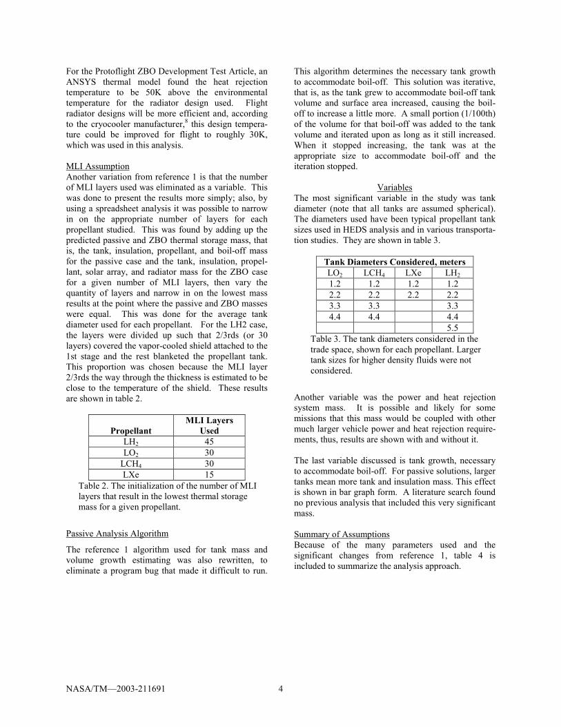
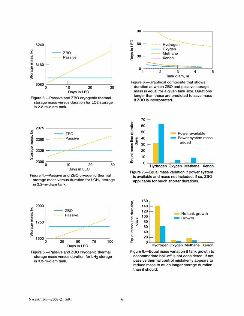
ZBO: Tank, insulation, propellant, cryocooler, solar array, radiator. The first graph (figure 3) includes passive and ZBO thermal storage mass predictions for oxygen as a function of storage duration, or the days in LEO with cryogens, regardless of the number of engine burns.
That graph is repeated twice more, for methane (fig. 4) and hydrogen (fig. 5). From those graphs and additional runs with xenon, the equal mass lines were constructed and are shown (fig. 6). These are the storage duration�s where the passive and ZBO masses are equal; durations longer than these are predicted to reduce mass for ZBO; durations shorter would benefit if passive storage was used. The bar graph in figure 7 shows the effect if power systems were available to power the cryocooler. Eliminating that mass from the trade reduces the
NASA/TM�2003-211691 6
Figure 3.—Passive and ZBO cryogenic thermal storage mass versus duration for LO2 storage in 2.2-m-diam tank.
60800 10
6160
6240
Sto
rag
e m
ass,
kg
20 30
ZBOPassive
Days in LEO
Figure 4.—Passive and ZBO cryogenic thermal storage mass versus duration for LCH4 storage in 2.2-m-diam tank.
23000 10
2325
2375
Sto
rag
e m
ass,
kg
2350
20 30
ZBOPassive
Days in LEO
Figure 5.—Passive and ZBO cryogenic thermal storage mass versus duration for LH2 storage in 3.3-m-diam tank.
15000 25
1750
2000
Sto
rag
e m
ass,
kg
50 75 100
ZBOPassive
Days in LEO
Figure 6.—Graphical composite that shows duration at which ZBO and passive storage mass is equal for a given tank size. Durations longer than these are predicted to save mass if ZBO is incorporated.
01 2
30
90
Day
s in
LE
O
60
3 4 5Tank diam, m
HydrogenOxygenMethaneXenon
Figure 7.—Equal mass variation if power system is available and mass not included. If so, ZBO applicable for much shorter durations.
0Hydrogen
10
70
Eq
ual m
ass
line
dur
atio
n,d
ays
20
30
40
50
60
Oxygen Methane Xenon
Power availablePower system mass added
Figure 8.—Equal mass variation if tank growth to accommodate boil-off is not considered. If not, passive thermal control mistakenly appears to reduce mass to much longer storage duration than it should.
0Hydrogen
20
160
Eq
ual m
ass
line
dur
atio
n,d
ays
406080
100120140
Oxygen Methane Xenon
No tank growthGrowth
NASA/TM�2003-211691 7
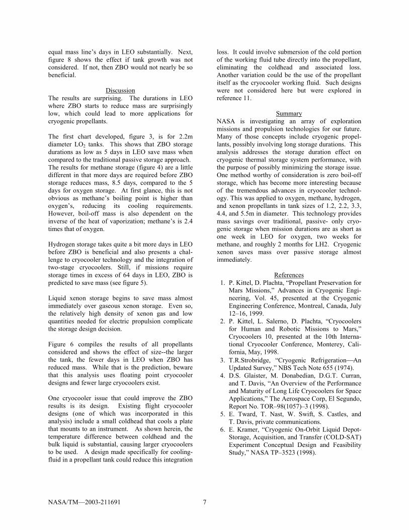
equal mass line�s days in LEO substantially. Next, figure 8 shows the effect if tank growth was not considered. If not, then ZBO would not nearly be so beneficial.
Discussion The results are surprising. The durations in LEO where ZBO starts to reduce mass are surprisingly low, which could lead to more applications for cryogenic propellants. The first chart developed, figure 3, is for 2.2m diameter LO2 tanks. This shows that ZBO storage durations as low as 5 days in LEO save mass when compared to the traditional passive storage approach. The results for methane storage (figure 4) are a little different in that more days are required before ZBO storage reduces mass, 8.5 days, compared to the 5 days for oxygen storage. At first glance, this is not obvious as methane�s boiling point is higher than oxygen�s, reducing its cooling requirements. However, boil-off mass is also dependent on the inverse of the heat of vaporization; methane�s is 2.4 times that of oxygen. Hydrogen storage takes quite a bit more days in LEO before ZBO is beneficial and also presents a chal-lenge to cryocooler technology and the integration of two-stage cryocoolers. Still, if missions require storage times in excess of 64 days in LEO, ZBO is predicted to save mass (see figure 5). Liquid xenon storage begins to save mass almost immediately over gaseous xenon storage. Even so, the relatively high density of xenon gas and low quantities needed for electric propulsion complicate the storage design decision. Figure 6 compiles the results of all propellants considered and shows the effect of size--the larger the tank, the fewer days in LEO when ZBO has reduced mass. While that is the prediction, beware that this analysis uses floating point cryocooler designs and fewer large cryocoolers exist. One cryocooler issue that could improve the ZBO results is its design. Existing flight cryocooler designs (one of which was incorporated in this analysis) include a small coldhead that cools a plate that mounts to an instrument. As shown herein, the temperature difference between coldhead and the bulk liquid is substantial, causing larger cryocoolers to be used. A design made specifically for cooling-fluid in a propellant tank could reduce this integration
loss. It could involve submersion of the cold portion of the working fluid tube directly into the propellant, eliminating the coldhead and associated loss. Another variation could be the use of the propellant itself as the cryocooler working fluid. Such designs were not considered here but were explored in reference 11.
Summary NASA is investigating an array of exploration missions and propulsion technologies for our future. Many of those concepts include cryogenic propel-lants, possibly involving long storage durations. This analysis addresses the storage duration effect on cryogenic thermal storage system performance, with the purpose of possibly minimizing the storage issue. One method worthy of consideration is zero boil-off storage, which has become more interesting because of the tremendous advances in cryocooler technol-ogy. This was applied to oxygen, methane, hydrogen, and xenon propellants in tank sizes of 1.2, 2.2, 3.3, 4.4, and 5.5m in diameter. This technology provides mass savings over traditional, passive- only cryo-genic storage when mission durations are as short as one week in LEO for oxygen, two weeks for methane, and roughly 2 months for LH2. Cryogenic xenon saves mass over passive storage almost immediately.
References 1. P. Kittel, D. Plachta, �Propellant Preservation for
Mars Missions,� Advances in Cryogenic Engi-neering, Vol. 45, presented at the Cryogenic Engineering Conference, Montreal, Canada, July 12�16, 1999.
2. P. Kittel, L. Salerno, D. Plachta, �Cryocoolers for Human and Robotic Missions to Mars,� Cryocoolers 10, presented at the 10th Interna-tional Cryocooler Conference, Monterey, Cali-fornia, May, 1998.
3. T.R.Strobridge, �Cryogenic RefrigerationAn Updated Survey,� NBS Tech Note 655 (1974).
4. D.S. Glaister, M. Donabedian, D.G.T. Curran, and T. Davis, �An Overview of the Performance and Maturity of Long Life Cryocoolers for Space Applications,� The Aerospace Corp, El Segundo, Report No. TOR�98(1057)�3 (1998).
5. E. Tward, T. Nast, W. Swift, S. Castles, and T. Davis, private communications.
6. E. Kramer, �Cryogenic On-Orbit Liquid Depot-Storage, Acquisition, and Transfer (COLD-SAT) Experiment Conceptual Design and Feasibility Study,� NASA TP�3523 (1998).

NASA/TM�2003-211691 8
7. L.J. Poth, J.R. Van Hook, �Control of the Thermodynamic State of Space-Stored Cryogens by Jet Mixing,� J. Spacecraft, Vol. 9, No.5, May, 1972.
8. C.K. Chan, TRW, private communications. 9. L.J. Hastings, J.J. Martin, �Large-Scale Liquid
Hydrogen Testing of a Variable Density Multi-layer Insulation with a Foam Substrate,� NASA/TM2001-211089, June 2001.
10. R.T. Parmley, W.C. Henninger, S.A. Katz, and I. Spradley, �Test and Evaluate Passive Orbital Disconnect Struts,� NASA CR�177368 (1985).
11. P.Kittel, �Propellant Preservation Using Re-liquefiers, Cryogenics 41 (2001) 841.
This publication is available from the NASA Center for AeroSpace Information, 301–621–0390.
REPORT DOCUMENTATION PAGE
2. REPORT DATE
19. SECURITY CLASSIFICATION OF ABSTRACT
18. SECURITY CLASSIFICATION OF THIS PAGE
Public reporting burden for this collection of information is estimated to average 1 hour per response, including the time for reviewing instructions, searching existing data sources,gathering and maintaining the data needed, and completing and reviewing the collection of information. Send comments regarding this burden estimate or any other aspect of thiscollection of information, including suggestions for reducing this burden, to Washington Headquarters Services, Directorate for Information Operations and Reports, 1215 JeffersonDavis Highway, Suite 1204, Arlington, VA 22202-4302, and to the Office of Management and Budget, Paperwork Reduction Project (0704-0188), Washington, DC 20503.
NSN 7540-01-280-5500 Standard Form 298 (Rev. 2-89)Prescribed by ANSI Std. Z39-18298-102
Form Approved
OMB No. 0704-0188
12b. DISTRIBUTION CODE
8. PERFORMING ORGANIZATION REPORT NUMBER
5. FUNDING NUMBERS
3. REPORT TYPE AND DATES COVERED
4. TITLE AND SUBTITLE
6. AUTHOR(S)
7. PERFORMING ORGANIZATION NAME(S) AND ADDRESS(ES)
11. SUPPLEMENTARY NOTES
12a. DISTRIBUTION/AVAILABILITY STATEMENT
13. ABSTRACT (Maximum 200 words)
14. SUBJECT TERMS
17. SECURITY CLASSIFICATION OF REPORT
16. PRICE CODE
15. NUMBER OF PAGES
20. LIMITATION OF ABSTRACT
Unclassified Unclassified
Technical Memorandum
Unclassified
National Aeronautics and Space AdministrationJohn H. Glenn Research Center at Lewis FieldCleveland, Ohio 44135–3191
1. AGENCY USE ONLY (Leave blank)
10. SPONSORING/MONITORING AGENCY REPORT NUMBER
9. SPONSORING/MONITORING AGENCY NAME(S) AND ADDRESS(ES)
National Aeronautics and Space AdministrationWashington, DC 20546–0001
Available electronically at http://gltrs.grc.nasa.gov
June 2003
NASA TM—2003-211691AIAA–2002–3589
E–13421
WU–706–87–13-00
14
An Updated Zero Boil-Off Cryogenic Propellant Storage Analysis Applied toUpper Stages or Depots in an LEO Environment
David Plachta and Peter Kittel
Cryogenics; Cryocoolers; Thermosyphons; Zero boil-off; Low-earth orbit; Orbit transfervehicles; Propellent depots; Long-term propellant storage
Unclassified -UnlimitedSubject Categories: 16, 20 and 28 Distribution: Nonstandard
Prepared for the 38th Joint Propulsion Conference and Exhibit cosponsored by AIAA, ASME, SAE, and ASEE,Indianapolis, Indiana, July 7–10, 2002. David Plachta, NASA Glenn Research Center, and Peter Kittel, NASA AmesResearch Center, Moffett Field, California 94035–1000. Responsible person, David Plachta, organization code 5870,216–977–7126.
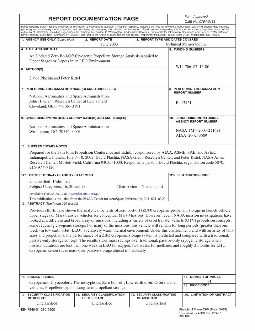
Previous efforts have shown the analytical benefits of zero boil-off (ZBO) cryogenic propellant storage in launch vehicleupper stages of Mars transfer vehicles for conceptual Mars Missions. However, recent NASA mission investigations havelooked at a different and broad array of missions, including a variety of orbit transfer vehicle (OTV) propulsion concepts,some requiring cryogenic storage. For many of the missions, this vehicle will remain for long periods (greater than oneweek) in low earth orbit (LEO), a relatively warm thermal environment. Under this environment, and with an array of tanksizes and propellants, the performance of a ZBO cryogenic storage system is predicted and compared with a traditional,passive-only storage concept. The results show mass savings over traditional, passive-only cryogenic storage whenmission durations are less than one week in LEO for oxygen, two weeks for methane, and roughly 2 months for LH2.Cryogenic xenon saves mass over passive storage almost immediately.