Embed Size (px)
Citation preview

c
ANALYSIS, TESTING AND PROPOSED GUIDELINES FORREPAIRING PIPELINES WITH COMPOSITE MATERIALS
Christopher R. AlexanderStress Engineering Services, Inc.
Houston, Texas
Fred D. WilsonAror Plate, Inc.Pasadena, Texas
SUMMARY
A considerable level of work has been conducted relating to the use of composite materials in repairing
corroded and mechanically-damaged pipelines. This paper presents information relating to the development
and testing of the Aror Plate Pipe Wrap (APPW 360), a fiberglass pipeline repair system for repairing pipes
with corrosion and mechanical damage. Due to its compliant nature, repair of fittings such as elbows and
tees is also permitted.
The purpose of this paper is two-fold. First, a list of proposed requirements for the pipeline industr is
submitted for assessing composite materials used to reinforce pipelines. While the authors do not claim that
the provided list covers all aspects on this issue, as a minimum it can be used as a spring board for the
development of an industr-accepted standards for composite repair methods. With the introduction of
several repair methods over the past several years, it is important that the pipeline industr be advised of the
critical; elements relating to any composite system.
The second intent of this paper is directed more toward application and testing of Aror Plate Pipe Wrap.
A test program was developed to address all aspects of the recommended guidelines presented in this paper.
Results of the experimental test program and details of the on-going research are provided.
1

INTRODUCTION
The introduction of composite pipeline repair methods has been a source of great interest over the past
several years. The primary aim of these repair methods is to reinforce the damage done to pipelines by both
corrosion and mechanical damage (such as dents and gouges), while alleviating the need for welding and in
some cases repairing with pressure in the pipeline. Typically, these repair processes involve issues such as
the following,
· Restoring the strength of a damaged pipe to the point where its burst pressure is increased to some
minimum amount (idealistically 100 percent of the undamaged burst pressure)
· Reducing the strain in the damaged areas of the pipe by providing reinforcement and increased
stiffness to the region in question
· Providing a restraint so that leak-before-break occurs (prevents failure by rupture), due to local
cracks developed as a result of corrosion or crack propagation in a dent or gouge.
· Sealing the damaged area of the pipe from further development of corrosion.
This section of the report is designed to provide the reader with an understanding of the critical issues
associated with the development of a composite pipeline repair system. The following list compiled by the
authors reflects the minimum requirements that any composite repair should meet. The need for industr
standardization in terms of required testing and qualifications is the motivation for providing this list.
1. The composite material used in the repair system should possess sufficient tensile strength (on the
order of 30,000 psi failure strength). The combination of the remaining pipe wall and composite
material should possess a failure strength that is at least equal to the specified minimum yield
strength (SMYS) of the pipe materiaL. Although a strength equal to 100 percent SMYS is sufficient,
it is recommended that a safety factor be placed on the maximum operating pressure (MOP). If MOP
is assumed to be 72 percent, a safety factor of two corresponds to a stress level of 144 percent
SMYS. While this may be an overly-conservative safety factor, the unknowns relating to the long-
term performance of composites in aggressive soil environments require that a conservative position
be taken.
2. The material should demonstrate that it can perform adequately in repairing corroded pipelines. This
involves strength in burst mode, but also involves ensuring that the repair does not degrade with time
or cyclic pressure service. Experimental testing must be conducted to address this issue. In
2

addressing the effects of cyclic operating pressures, the service conditions in actual operating lines
should be considered. A tyical liquid pipeline may see approximately 1,800 cycles per year (at a
200 psi pressure differential), while gas transmission lines see 10 times fewer, or 60 cycles, for the
same pressure leveL.
3. Testing should be conducted to address creep of the material under dead weight loading.
Idealistically, a battery of tests should be conducted using weights as a percentage of the lower
bound failure load for the given material (e.g. 10,25, and 50 percent of tensile failure strength).
Creep testing should also be conducted over several different loading time periods (e.g. 24 hours,
6 months, 2 years, etc.).
4. Lap shear testing should be conducted to ensure that an adequate bond exists between the pipe and
wrap. For composite repair methods that are not monolithic (monolithic meaning that all layers
combine to form a homogenous unit), these tests should also include composite-composite test
samples as well as the composite-steel test coupons. The composite-composite sample is used to
assess the bond strength between the layers, while the composite-steel samples are used to determine
the lap shear strength at the interface between the pipe material and composite.
S. Testing should be conducted to address cathodic disbondment and the system should meet the
requirements as set forth in ASTM G8 (Standard Test Methods of Cathodic Disbondingfor Pipeline
Coatings).
6. Repair materials should resist mild acid and alkaline environments, including a range of 4 to 11 pH.
Alkaline soils may have a pH of 11 or higher, which wil attack fiberglass and polyester resin. In
general, epoxies can handle mild acids and strong alkalines.
7. Testing should be conducted to address water penetration into the system using test method ASTM
G9 (Standard Test Methodfor Water Penetration and Pipeline Coatings).
8. The composite material should be able to withstand temperatures of the operating line on which it
is to be installed. The operator should consider the effects of temperature in selecting regions of
application (e.g. compressor station may see temperatures of 205°F).
9. Product must be environmentally-safe and possess low toxicity for the applicator.
10. To minimize the possibility for improper installation, the system must be user-friendly and have
instructions that are easily understood. For two-part systems, the greatest problem associated with
improper application involves incorrect mixing of the adhesive. Installation should only be
conducted by a certified applicator.
3

11. The product must have clearly stated on it the expiration date (if applicable) of any component
within the system. The system must demonstrate that it possesses adequate strength over a long
period of time (2 to 3 year testing period). This should involve testing of the composite itself as well
as adhesive bonds under load. Samples should be exposed to harsh environments (such as saturation
in water) where composite properties are known to degrade with time.
12. A field monitoring program should be conducted to assess performance of the wrap over several
years. This involves inspection of the buried line at least one year after installation. The repair
should be inspected for soundness and any possible signs of degradation. Strain gages should be
installed beneath the wrap to determine any changes in the pipe strain that occur with time.
13. The adhesive system must demonstrate that it can be used in a variety of temperature environments
and permit installation in a range of ambient temperature conditions (e.g. between OaF and 120°F).
Ultimate responsibility is on the operator to ensure that the system can adequately cure and is not
damaged at elevated ambient conditions.
14. The cured material should have a minimum Barcol hardness of 40.
15. For cold weather applications, the system should have sufficient toughness to ensure that the
material does not become brittle and lose its ability to properly reinforce the pipeline.
16. When a repair method is used for restoring corroded pipes, calculations relating to its strength
should incorporate severity of the corrosion using methods such as those used in ANSI/ AS ME
B3IG.
As stated previously, the objectives of this paper are to provide a list of minimum requirements for
composite materials used to repair pipelines and introduce specific information relating to a program
developed to test the Aror Plate Pipe Wrap repair system. This paper does not address all aspects of
composites used in repairing pipelines, but limits itself to discussing details of the Aror Plate Pipe Wrap
test program.
4

EXPERIMENTAL TEST PROGRAM
To validate Aror Plate Pipe Wrap as a viable pipeline repair method, a testing program has been developed.
The major components of the current test program are,
· Repair of corrosion
· Cyclic pressure effects on burst pressure of a repaired corrosion sample
· Load transfer from pipe to wrap using strain gages
· Testing to address installing APPW 360 on pipes with different internal pressures
· Installation of APPW 360 in repairing corroded elbow and tee pipe fittings
· Tensile testing of the APPW 360 composite material
· Lap shear testing to address the interface between the composite and steel.
Presented in this section of the paper are the test methods and results associated with the investigation of
these experimental variables. A later section wil discuss issues relating to the long-term test program.
Repair of Corrosion
Several samples were specifically fabricated to address the reinforcement of corrosion using the APPW 360.
Corrosion defects were machined in 6 inch and 12 inch nominal pipes. The corrosion lengths were selected
so that without repair the corrosion would have failed at a pressure less than the safe maximum pressure per
ASME B31 G. These corroded sections of pipe, assuming they were present on an actual pipeline, would need
to be removed, repaired, or have the operating pressures reduced.
Prior to installing the wrap on each sample, the pipe was sandblasted to a near-white metal finish with a 2.5
to 3-mil anchor pattern. End caps were then attached to the pipe by welding. The wrap was installed with
no internal pressure in the pipe. The remaining steps in terms of installing the wraps were conducted by
Aror Plate, Inc. personnel and are as follows,
· Primed surfaces where the wrap was to be installed with Aror Plate 360 A&B
· Filed in the corrosion region of the sample using AP360 epoxy putty
· Installed wraps having 8 layers over the corroded region
· The edges of the wrap were contoured with AP360 epoxy putt
· The wrap cures suffciently when placed beneath a heating blanket for one hour at 130°F.
5

Figure 1 shows Aror Plate Pipe Wrap being installed on a test sample and Figure 2 is a photograph of a
completed installation on a pipeline.
Listed in Table 1 are the sample descriptions and test results for the corrosion test samples. The minimum
pressure that any repair should achieve is the 100 percent SMYS pressure; however, the APPW 360 system
is designed to provide reinforcement up to two times the B31.4 maximum operating pressure or B31.8
maximum allowable operating pressure (144 percent SMYS) assuming that the appropriate number of wraps
is applied.
As noted in all three tests, the burst pressure for the repaired samples exceeded not only the 100 percent
SMYS pressure, but were also greater than the predicted failure pressures for the base pipe material assuming
no defects were present. None of the repaired samples failed at pressures less than the expected burst
pressure for pipe without corrosion or defects.
Cyclic pressure effects on burst pressure
In an effort to address the effects of cyclic pressure on the strength ofAPPW 360, a test sample was cycled
3,290 times prior to conducting a burst test. Data is provided in Table 1 relating to this particular test,
Sample WC-4F. As shown, the burst failure pressure for this sample is equal (within 24 psi) to the burst
pressure for the non-cycled test, Sample WC-3B. Based upon an industr survey relating to tyical operating
pressure fluctuations for liquid pipelines (Fowler et aI., 1994), pressure fluctuations of this order (1, i 00 psi)
would occur less than 500 times per year. This being the case, the 3,290 cycles for Sample WC-4F
correspond to approximately six years of service in a liquid pipeline. In contrast with liquid service, cyclic
pressure is tyically not an operating issue for gas pipelines (pressure fluctuations of 200 psi every five
months, Fowler et aI., 1994)
Strain Gage Testing
Strain gages were installed on one section of a 16-in x 0.37S-in, grade XS2 pipe to determine the level of
restraint provided by the APPW 360 repair system. In addition to the gages installed under the wrap, one
exterior gages was installed on the pipe away from the wrap. These locations served to indicate the level of
nominal strain in the pipe due to internal pressure.
6

An 8-in x 8-in corrosion area having a depth of SO percent was machined into the 0.375 inch wall. This
thickness was verified to be 0.188 inches using a hand-held ultrasonic meter. Two biaxial strain gage rosettes
were installed in this region. One was placed in the center of the corrosion, while the other was offset 2
inches along the axis of the pipe.
After installation of the wrap was complete, the strain gages and associated cables were connected a data
acquisition system. This equipment was necessary for monitoring the strain gages during the pressurization
process. This step was the last procedure conducted before testing the wraps.
The level of internal pressure was related to the minimum specified yield strength for the pipe. The XS2
grade pipe has a SMYS of 52,000 psi which corresponds to a pressure of 2,438 psi. According to ASME
Codes for liquid and gas piping, the allowable stress is limited to 72 percent of SMYS (for B31.4 all cases
and for B31.8, Division 1, Class 2 - pipelines, mains, and service lines), which for the given pipe corresponds
to an internal pressure of 1,755 psi. Using these two pressure values (1,755 and 2,438 psi), a pressure
sequence was developed for testing the pipe sample. Figure 3 shows the pressure-time map used in loading
the sample. The three pressure cycles shown were applied three different times, being designated as Run #1
and Run #2, and Run #3. The purpose in repeating the pressure cycles was to provide information relating
to the hysteresis of the system.
The properties for the 16-inch pipe according to the Mil Test Report were,
· Yield strength of 68,900 psi (API Spec SL minimum yield strength of 52,000 psi)
· Tensile strength of 88,500 psi (API Spec SL minimum tensile strength of 66,000 psi)
· Elongation of 35.0% (API Spec SL minimum of 23 .5%).
As can be seen from these values, the tested pipe far exceeds the minimum values for the XS2 grade piping
material as specified by the American Petroleum Institute's (API) Specification SL. While strain gages were
installed in the corroded region of the 16-inch pipe beneath the wrap, no measurements were taken in this
region without reinforcement. For this reason a finite element analysis (FEA) model was constrcted to
determine the strains in an unrepaired corroded region. Figure 4 provides the analytical results with the
experimental values for the strain gages located in the corroded region beneath the APPW 360 wrap. In the
7

finite element model, strains were extracted from the same location as the strain gages placed on the 16-inch
pipe test sample.
In studying the information in Figure 4, there are several noteworthy observations,
. In the initial pressurization, the wrap does not provide significant reinforcement to the corroded
region of the pipe. This is validated in observing that the sub-wrap strain values differ little from the
nominal pipe strain readings.
. During the later stages of the pressurization (after approximately 2,000 psi internal pressure), the
strain in the pipe increases significantly. It is at this point that the wrap begins to take on the load
required to provide restraint to the pipe. At the maximum pressure of2,438 psi, it is apparent that
the wrap is providing reinforcement to the corroded region. Using the previous equations and the
ultimate strength of the pipe, the calculated burst pressure for the corroded region without
reinforcement is 2,476 psi.
. Using the hand calculations and FEA results, it is apparent that the pipe repair is providing
reinforcement once the corroded region exhibits yielding. If the APPW 360 repair was not installed,
the two sets of plotted curves (red/lue and yellow/green) would be more closely related.
While strain gages were not installed in a corroded region that was not repaired, the finite element analysis
provides useful information relating to the expected stress/strain levels. This comparison of results provides
insights as to the mechanical behavior of the wrap and at what pressure the transformation of the load from
the pipe to the wrap occurs.
Effects of Installation Pressure on Performance of APPW 360
One issue commonly raised when discussing any repair method is the pipe internal pressure at which
installation of the repair can be made. When discussing composite repairs, this is perceived by many as an
important issue. To address the effects of installing Aror Plate Pipe Wrap at different pressures, a series
of tests were devised using three 12.7S-in x 0.l88-in, grade X42 pipe samples. An 8-in x 8-in region was
machined in each of the 8- feet long samples having a depth of SO percent of the nominal wall. Based on the
remaining wall thickness in the corroded regions of the pipes, the pressure required to cause yielding was
calculated to be 585 psi. Each of the samples were pressurized prior to installation of the wraps so that a 0.20
percent strain was induced, which corresponded experimentally to an internal pressure of 600 psi. The
8
purpose of this stage of testing was to insure that yielding had occurred in the pipe prior to installation of
the wrap. During installation of the wraps, one sample was pressurized to 540 psi (90 percent of 600 psi),
another at 270 psi, and a third sample had no pressure during installation. The wraps were installed and cured
beneath a heat blanket for one hour at 130°F. Burst tests were conducted and all three test samples failed at
pressures of 2,240 psi. This pressure is on the same order as the ultimate tensile strength pressure for the
given pipe materiaL. The results associated with this series of tests clearly indicate that the burst strength of
the Aror Plate repair system is not significantly affected by variations in installation pressure.
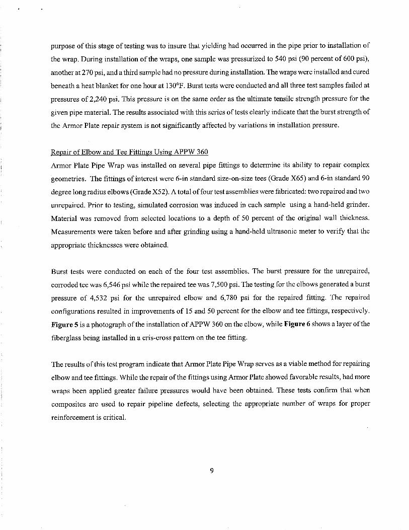
Repair of Elbow and Tee Fittings Using APPW 360
Aror Plate Pipe Wrap was installed on several pipe fittings to determine its ability to repair complex
geometries. The fittings of interest were 6-in standard size-on-size tees (Grade X6S) and 6-in standard 90
degree long radius elbows (Grade XS2). A total of four test assemblies were fabricated: two repaired and two
unrepaired. Prior to testing, simulated corrosion was induced in each sample using a hand-held grinder.
Material was removed from selected locations to a depth of SO percent of the original wall thickness.
Measurements were taken before and after grinding using a hand-held ultrasonic meter to verify that the
appropriate thicknesses were obtained.
Burst tests were conducted on each of the four test assemblies. The burst pressure for the unrepaired,
corroded tee was 6,546 psi while the repaired tee was 7,500 psi. The testing for the elbows generated a burst
pressure of 4,532 psi for the unrepaired elbow and 6,780 psi for the repaired fitting. The repaired
configurations resulted in improvements of 15 and SO percent for the elbow and tee fittings, respectively.
Figure 5 is a photograph of the installation of APPW 360 on the elbow, while Figure 6 shows a layer of the
fiberglass being installed in a cris-cross pattern on the tee fitting.
The results of this test program indicate that Aror Plate Pipe Wrap serves as a viable method for repairing
elbow and tee fittings. While the repair of the fittings using Aror Plate showed favorable results, had more
wraps been applied greater failure pressures would have been obtained. These tests confirm that when
composites are used to repair pipeline defects, selecting the appropriate number of wraps for proper
reinforcement is criticaL.
9

Composite Tensile Testing
Aror Plate, Inc. fabricated several flat panels of the APPW 360 composite materiaL. The approximate
dimensions for each of the panels were 6 inches wide by 12 inches long, with thickness being dependent
upon the number oflayers. Testing was conducted on two and four-layer samples. Identical I-in x 8-1I2-in
samples were prepared from each of the panels. The fibers of the composite were oriented with the long
direction of the samples. Tensile testing was conducted using a constant cross-head speed of 0.05
inches/minute in a laboratory temperature of 70°F. The output for the testing procedure was load and
deflection; however, using the cross-sectional area of the samples and gage length, stress and strain were
computed, respectively. Also obtained as a result of the testing was the modulus of elasticity. The modulus
of elasticity, E, is calculated by dividing change in stress by change in strain for the linear portion of the
load-deflection curve. During the testing, deflection was only monitored to approximately 75 percent of
failure due to the potential for damaging the deflection-measuring extensometer at the point of rupture.
Based on the test results, the average failure stress for the AP 360 epoxy formulation was 26,441 psi, while
the average modulus of elasticity was 1.75 x 10⁶ psi.
Lap Shear Testing
While testing has been reported herein relating to the performance of the pipeline wrap in reinforcing pipe
defects as well as determining the composite tensile strength, information has not been presented relating
to the adhesive bond between the pipe and composite. The most effective method for evaluating this interface
is by using lap shear samples. In this application, the lap shear testing method uses either steel or composite
adherends to test the adhesive bond. As shown in Figure 7, the adherends are assembled to create a tensile
coupon with a test zone having an area of one square inch. The sample is loaded to the point where failure
occurs. This failure shear stress is known as the lap shear rupture strength. In addition to the rupture method
ofloading, the lap shear samples can be used to determine creep in the adhesive bond considering a specified
load, temperature and time period.
Aror Plate, Inc. fabricated two panels involving a steel-on-steel assembly and a composite-on-steel
assembly. The approximate dimensions for each of the assembled panels were 7 inches wide by 9 inches
long. The nominal adhesive thickness for the samples was 0.010 inches. From these panels, I-inch wide
samples were cut.
10

Of the two lap shear adherend combinations, the composite-on-steellap shear sample is more representative
of the actual application. In addition to the general strength ofthe composite material, the bond between the
pipe and steel pipe ( adhesive interface) determines the strctural integrity of the repair method.
The lap shear testing was conducted using a constant cross-head speed of 0.05 inches/minute in a laboratory
temperature of70°F. The output for the testing procedure was load and deflection; however, using the cross-
sectional area of the adhesive, the failed shear stress was computed. The steel-on-composite failures all
resulted in fiber pull out from the composite. The average failure shear stress for the steel-on-steel and steel-
on-composite samples were 1,504 psi and 1,495 psi, respectively. Had fiber pull out not occurred with the
composite material, the disbonding of the steel-on-composite samples would have occurred at higher shear
stresses.
PROPOSED TEST PROGRAM TO ADDRESS ADDITIONAL ISSUES
The initial test program employed by Armor Plate, Inc. to evaluate the pipeline repair system addressed
issues relating to the pressure-capacity restoration of damaged pipes. Results for this test program are
provided herein. While favorable hydrostatic burst and short-term cyclic have been obtained using a limited
number of samples, it is recognized that long-term issues such as creep and environmental effects have not
been addressed thoroughly. For this reason, Aror Plate, Inc. has included this section of the paper to
provide information regarding the long-term test program. This list below provides an outline of the testing
needed to address performance of the adhesive and composite system for long-term service.
. Strength rupture and creep testing on the composite material (including elevated temperatue testing)
· Strength rupture and creep testing on lap shear samples addressing bond strength between pipe and
wrap (including elevated temperature testing)
. Cathodic disbondment and water penetrations testing (per ASTM GS and G9 test procedures)
. Long-term composite and lap shear testing (dead weight loading in saturated environment)
· Field validation program involving installation of wraps on pipelines that wil be monitored over
several years. A standard method for installation and inspection should be employed for all wraps
installed.
· Installation of Aror Plate on pipes having mechanical damage (dents with gouges) subjected to
cyclic pressure service. The results for the repaired test samples will be compared to the results of
fatigue test failures for unrepaired test samples.
11
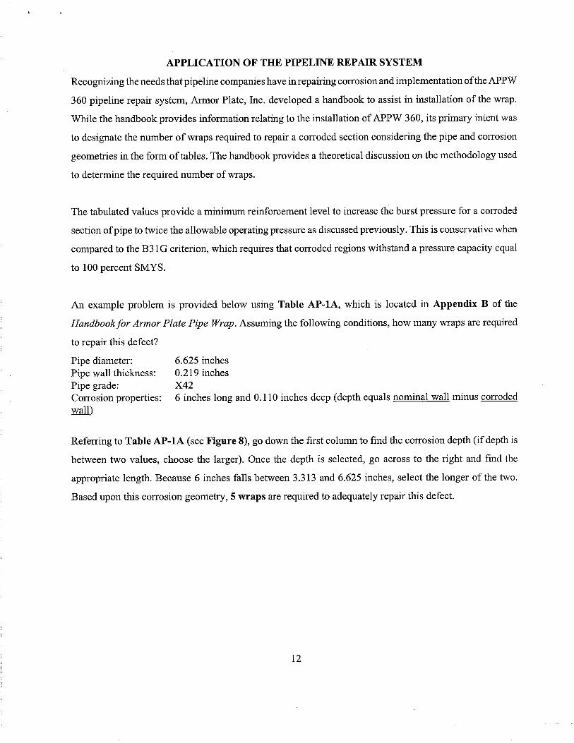
APPLICATION OF THE PIPELINE REPAIR SYSTEM
Recognizing the needs that pipeline companies have in repairing corrosion and implementation of the APPW
360 pipeline repair system, Aror Plate, Inc. developed a handbook to assist in installation of the wrap.
While the handbook provides information relating to the installation of APPW 360, its primary intent was
to designate the number of wraps required to repair a corroded section considering the pipe and corrosion
geometries in the form of tables. The handbook provides a theoretical discussion on the methodology used
to determine the required number of wraps.
The tabulated values provide a minimuIl reinforcement level to increase the burst pressure for a corroded
section of pipe to twice the allowable operating pressure as discussed previously. This is conservative when
compared to the B31 G criterion, which requires that corroded regions withstand a pressure capacity equal
to 100 percent SMYS.
An example problem is provided below using Table AP-IA, which is located in Appendix B of the
Handbookfor Armor Plate Pipe Wrap. Assuming the following conditions, how many wraps are required
to repair this defect?
Pipe diameter:
Pipe wall thickness:Pipe grade:
Corrosion properties:wall
6.625 inches0.219 inches
X426 inches long and 0.110 inches deep (depth equals nominal wall minus corroded
Referring to Table AP-IA (see Figure 8), go down the first column to find the corrosion depth (if depth is
between two values, choose the larger). Once the depth is selected, go across to the right and find the
appropriate length. Because 6 inches falls between 3.313 and 6.625 inches, select the longer of the two.
Based upon this corrosion geometr,S wraps are required to adequately repair this defect.
12

CONCLUDING REMARS
Based upon results of the test program, the Aror Plate Pipe Wrap has proven itself to be an effective
method forrepairing corroded and mechanically-damaged pipe by increasing the hydrostatic burst capacity.
Repairs of elbow and tee pipe fittings have also been conducted with favorable results. In addition to the pipe
testing, investigations have been conducted relating to the adhesive and composite system. These tests have
also proved that the proposed repair system possesses adequate strength characteristics.
To address longevity of the repair method, the Aror Plate, Inc. long-term test program is designed to deal
with concerns relating to environmental issues and performance of the composite/adhesive system over an
extended period of time under load. This document has attempted to present information relating to the
current test program as well as the proposed long-term research efforts. The objective of the overall test
program is to fit within a standardized method that wil be required for establishing the fitness of composite
repair methods.
REFERENCES
Alexander, C. R., Handbookfor Armor Plate Pipe Wrap, prepared by Stress Engineering Services, Inc. forAror Plate, Inc., Houston, Texas, April 1998.
Alexander, C. R., Ross, G. R. and Fowler, J. R., Testing of Armor Plate Pipe Wrap using Tensile Couponsand Strain Gage Measurements Taken from 16" Pipe Assembly, prepared by Stress Engineering Services,Inc. for Aror Plate, Inc., Houston, Texas, February 1998.
Alexander, C. R. and Biel, R. C., Experimental Testing of Armor Plate Pipe Wrap (APPW 360) - Report #2,prepared by Stress Engineering Services, Inc. for Aror Plate, Inc., Houston, Texas, February 1998.
Alexander, C. R. and Kiefner, 1. F., Effects of Smooth and Rock Dents on Liquid Petroleum Pipelines, APIPublication 1156 (First Edition), American Petroleum Institute, Washington, D.C., November 1997.
American Society of Mechanical Engineers, Manualfor Determining the Remaining Strength of CorrodedPipelines, ASME B31G-1991, New York, New York, 1991 edition.
American Society of Mechanical Engineers, Liquid Transportation System for Hydrocarbons, LiquidPetroleum Gas, Anhydrous Ammonia and Alcohols, ASME B31.4, New York, New York, 1992 edition.
American Society of Mechanical Engineers, Gas Transmission and Distribution Piping Systems, ASMEB31.8, New York, New York, 1995 edition.
13

American Society of Testing and Materials, Paint - Products and Applications: Protective Coatings; PipingCoatings, Volume 6.02, West Conshohocken, Pennsylvania, 1998 edition.
Fowler, J. R. Alexander, C. R., Kovach, P. J., and Connelly, L. M.,FatigueLife of Pipelines with Dents and
Gouges Subjected to Cyclic Internal Pressure, Energy-Sources Technology Conference and Exhibition,Houston, Texas, February 1995.
Kiefner, J. F., and Vieth, P. V., New method corrects criterion for evaluating corroded pipe, Oil and GasJournal, August 9, 1990, pages 56-59.
Kuhlman, C. J., Lindholm, U. S., Stephens, D. R., and Kilinski, T. J., Long- Term Reliability of Gas Pipeline
Repairs by Reinforced Composites, Final Report to the Gas Research Institute, Chicago, Ilinois, GRI-95/0071, December 1995.
Stephens, D. R. and Kilinski, T. J., Field Validation of Composite Repair of Gas Transmission Pipelines,
Final Report to the Gas Research Institute, Chicago, Ilinois, GRI-98/0032, April 1998.
Sample Sample Description SMYS Predicted burst Predicted burst Actual burst
Number pressure pressure for pressure for pressure (3)
uncorroded pipe (I) corroded pipe (2)
WC-3B 12.75" X 0.188" W.t. pipe, grade X52 1,533 psi 2,284 psi 974 psi 2,289 psi
50% corrosion (24" long by 8" wide)taclU'1 = 0.191 inches (base pipe material)tmin = 0.078 inches (in corrosion)Pipe yield strength = 49,000 psiPipe tensile strength = 76,250 psi
(7 wraps used, 7 reqd. by handbook tables)
WC-4F 12.75" X 0.188" W.t. pipe, grade X52 1,533 psi 2,284 psi 974 psi 2,313 psi
50% corrosion (24" long by 8" wide)tactu.1 = 0.191 inches (base pipe material)4n = 0.078 inches (in corrosion)Pipe yield strength = 49,000 psiPipe tensile strength = 76,250 psi
(sample pressure cycled 3,290 times prior toburst with ßP = 100 to 1200 psi)
(7 wraps used, 7 reqd. by handbook tables)
Pipe #2 6.625" X 0.280" W.t. pipe, grade X46 3,888 psi 5,968 psi 3,629 psi. 6,170 psi
50% corrosion (4" long by 4" wide)taciu.i = 0.280 inches (base pipe material)tmin = 0.140 inches (in corrosion)Pipe yield strength = 47,500 psiPipe tensile strength = 70,600 psi
(4 wraps used, 6 reqd. by handbook tables)
Table 1 Repaired Burst Test Samples
Notes:
(I) Predicted burst pressure based on actnal wall thickness and ultimate tensile strength of pipe
(2) Predicted burst pressures for corroded pipes based on ultimate strength of pipe and reduction factor to account for corroded wall thickness(3) Burst pressures for the repaired samples exceeded not only 100 percent SMYS, but were also greater than the predicted failure pressures for the base pipe materialassuming no defects were present.
14

Figure 1 Installation of Aror Plate Pipe Wrap
Figure 2 Completed installation of Aror Plate Pipe Wrap
15

Figure 5 Installation of APPW 360 on elbow with corrosion
Figure 6 Installation of APPW 360 in a cris-cross pattern on tee
16

~ëê8,c.~
û5c.oo:r
3000
Ä~
j
2000
Order of Operation:o minutes Start (up to 1755 psi, 10 psi/second)3 minutes Arrive at 1755 psi, 1 minute hold4 minutes Come down in pressure to 0 psi5 minutes 0 psi, start up again to 1755 psi8 minutes Arrive at 1755 psi, 1 minute hold9 minutes Come down in pressure to 0 psi10 minutes 0 psi, start up again to 2438 psi13 minutes Arrive at 2438 psi, 1 minute hold14 minutes Come down In pressure to 0 psi
1000
o
o 5 10Time (minutes)
15
Figure 3 Pressure-time map used in experimental testing
HOOP STRAIN AS A FUNCTION OF PRESSUREIN CORRODED REGION OF PIPE CONSIDERINGEXPERIMENTAL AND FINITE ELEMENT VALUES
Calculated FEA and experimental results assume a 16" X 0.375" pipe with a 8" X 8" corrosionpatch, 50% of the wall (X52 grade pipe). Experimental corroded region wrapped with 8 layers
of APPW 360. Testing and analysis conducted by Stress Engineering Services, Inc.
2.50
2.00
Note:1. Exparimenial strain values obtained using strain gages localed
beneath the APPW 360 wrap (2 bi-axial gages used)2. Two strain gages placed beneath the APPW 360 wrap. one positioned
longitudinally in the center and the other 2" from the center of thecorrosion along the axis of the pipe.
3. Finite elemant analysis (FEA) results obtained using shell elementsto model pipe, end caps, and 50% corrosion patch. Material modelfor FEA based upon non-linear elastic-plastic values using the yieldand ultimate strength for the actal pipe.
Legend
-t FEA - Center of Corrsion
~ FEA - 2" from Center of Corrosion
~B- Experimental- Center of Corrosion
......tJ Experimental- 2" from Center of Corrosion
1.50
1.00
0.50Experimental APPW 360strain results
0.00"..\! ",," .....",,\!~.
o 1000 2000 3000Internal Pressure (psi)
Figure 4 Hoop strain as a function of pressure for experimental and analytical work
17

8.75 inches
inches (approx.) I~0.25 inches JAdhesive bond
Steel on Steel Lap Shear Sample
steel Adherend I
inches
I, 1.25 inches (approx.)Composite Adherend
8.75 ~Adhesive bond area ~ Sleel Plate 0.25 inches J
Composite on Steel Lap Shear Sample
Figure 7 Configuration of lap shear test samples used in testing
Pipe Diameter (in) 6.625 I Notes:
PIpe wall thickness (in) 0.219 1. Repair is not required if corrsion length In table is less than the calculated limiting corrosion length. L. per 831G (see last column in
Pipe Grade (Spec API 5L) X42 table).
SMYS (psi) 42000 2. If operating pressure is greater than the calculated MAOP, then a specifc calculation for the given pipe, grade and operating pressureis required.
UTS (psi) 60000 3. If the pipe grade (e.g. X52) has a yield strength that is greater than X42 material, then a specifc calculation for the given pipe, gradeWrap UTS (psi) 30000 and operating pressure is required jf a greater level of reinforcement is desired from the wrap (if wrap thickness value from table are used.
MAOP (psi) 1999 result is conservative if operating pressure less than calculated MAOP at left)Maximum pennitted 4. NR in cell means that repair is not necessary per B31G for this particular corrsion length.
corrosion depth (inches) 0.175
Required Number ot wraps
Corrosion DepthCorrosion Length percentage a pipe aiameter an i iength in Inches)
(inches)5'10 U 10%D 25%D 50% D 1000 U 150%D 200%D Infinite L per 831tjU.""l U.oo" 1.656 3.313 O.O;¿O ~.\""tl 13.250 luuuu Incr es
0.022 NK NK NK ~ 1 1 1 5.396
0.033 NK NK NK ~ 2 2 2 ~. 5.396
U.U44 NK NK NK NK 2 2 2 2 3.611
0.055 NR NR NR 2 2 3 3 3 2.337
0.066 NK NR NR 2 3 3 3 3 1.799
0.077 NK NK 2 3 3 3 3 4 1.489
0.088 NK NK 2 3 4 4 4 -4 1.2tl;¿
0.099 NK NK 3 4 4 4 4 5 1.130
u.i10 NK NK 3 4 5 5 5 5 1.012
0.120 NR NR 3 4 5 5 5 6 0.916
0.131 NR NR 4 5 b 6 6 6 U.ö"b
0.142 NR NR 4 5 6 6 6 7 0.767
0.153 NK NK 5 6 7 7 7 0.707
0.164 NK 3 5 7 7 7 7 0.653
0.170 NK 3 ö f tl tl tl -8 U.öUo
Figure 8 Table AP-1A from the Armor Plate Pipe Wrap Handbook
18