Embed Size (px)
Citation preview

Proceedings of the 6th International Offshore Pipeline Forum IOPF 2011
October 19-20, 2011, Houston, Texas, USA
IOPF2011-4002
© Copyright 2011 ASME 1
EVALUALTING THE PERFORMANCE OF A COMPOSITE-REINFORCED STEEL
DRILLING RISER VIA FULL-SCALE TESTING FOR HPHT SERVICE
Chris Alexander Stress Engineering Services, Inc.
Houston, Texas [email protected]
Chad Cederberg
Lincoln Composites Lincoln, Nebraska
Brent Vyvial Stress Engineering Services, Inc.
Houston, Texas [email protected]
Don Baldwin
Lincoln Composites Lincoln, Nebraska
ABSTRACT A program was undertaken to evaluate the performance of a composite-reinforced steel riser for deepwater HPHT service via full-scale testing. This program was sponsored by the RPSEA (Research Partnership to Secure Energy for America) Deepwater Program that involved the design, fabrication, and testing of three prototype test samples. Lincoln Composites completed the design, analysis, and fabrication of test samples that were subjected to internal pressure, bending, and impact loadings. Stress Engineering Services, Inc. was responsible for destructively testing the samples. The design requirements for the riser included the following: 10,000 ft water depth, internal pressure of 15,000 psi, top tension capacity of 3,000 kips, 20-year service life, service temperature ranging from 32 to 180 °F, and a drift diameter 19.5 inches. The purpose in testing was to demonstrate that an acceptable design margin exists between the design and limit state conditions. The results of the test program demonstrated that a safety factor of 2.60 exists when comparing the 15 ksi design conditions to the burst pressure for one of the test samples that was included in this program. The failure for this particular sample occurred at 39,086 psi. During testing, strain gages were used to monitor strain on the outer surface of the carbon material. Good correlation was observed between the target design conditions based on finite element work and the data recorded during testing. With increased drilling at deeper water depths, including high pressure and high temperature conditions, the demands for game-changing technology is essential if the offshore industry is to operate safely and economically at these environmental conditions. INTRODUCTION Scaling conventional riser technology for ultra-deepwater and high pressure has a prohibitive impact on the required wall thickness and riser weight. A heavier riser requires a corresponding increase in tensioning capability, structural capacity of the supporting platform, and its equipment; making necessary larger and more expensive floating structures. In addition to the costs associated with supporting such a riser, existing fabrication methods may not be feasible at the required thickness. An alternative to accommodating heavier risers is to reinforce existing riser constructions with high-strength and lightweight composite materials. By virtue of a much higher specific strength, an equivalent
increase in X80 pipe thickness can be made with composite materials at one-fifth of the weight. Design methods from the pressure vessel industry for optimizing utilization and reliability of composite over-wrapped metal pressure vessels may also be applied to risers to further improve performance. Preceding investigations have suggested a weight savings potential on order of fifty percent for a composite-reinforced riser in comparison to all steel construction. The objective of this project is to develop and commercialize a dry tree riser system for ultra-deepwater and high pressure that is suitable for existing tension-leg (TLP) or spar platforms using industry standard equipment. The project has been planned in phases; beginning with design and proof of concept testing, followed by design qualification, field demonstration, and ending with commercialization. TESTING METHODS A total of three riser prototypes were manufactured by Lincoln Composites for the test program. The following tests were performed on the riser prototypes: 1. Burst Test (SN1)
• Autofrettage cycle to 20,000 psi • Proof cycle to 18,750 psi • Preconditioning cycles (20) to 16,500 psi • Pressure test to failure
2. Bending Cycles/ Burst Test (SN2) • Autofrettage cycle to 20,000 psi • Apply 100,000 bending cycles of +735 ft-kips to -560 ft-
kips with internal pressure of 7,790 psi • Pressure test to failure
3. Impact Test/ Bending Cycles/ Burst Test (SN3) • Autofrettage cycle to 20,000 psi • Drop 10,000 lbs from 5 ft at three locations along riser • Pressure test to 15,000 psi • Apply 100,000 bending cycles of +735 ft-kips to -560 ft-
kips with internal pressure of 7,790 psi • Pressure test to failure
A total of 20 tri-axial strain gage rosettes were bonded to the risers in each phase. The gages were 0o, 45o, 90o rosettes from Micro-Measurements Group (CEA-06-125UR-350).
© Copyright 2011 ASME 2
Strain gages 1-4 were 78.2 inches from end-A, gages 5-8 were 125.1 inches from end-A, gages 9-12 were in the center of the riser, gages 13-16 were 125.1 inches from end-B, and gages 17-20 were 78.2 inches from end-B. Gages 1, 5, 9, 13, and 17 were placed at 0o along the tube. Gages 2, 6, 10, 14, and 18 were placed at 90o along the tube. Gages 3, 7, 11, 15, and 19 were placed at 180o along the tube. Gages 4, 8, 12, 16, and 20 were placed at 270o along the tube. A diagram of the strain gage locations is shown in Figure 1. Displacement transducers were used to measure circumferential expansion at locations of 165.5 (station-A) inches and 266.5 (station-B) inches from end-A. The overall change in length was measured at 0o and 180o. Change in length was also measured between Station-A and Station-B at 0o and 180o. Strain gage readings, pressure transducers, and displacement transducers were all recorded using StrainDAQ software and hardware. The StrainDAQ system is comprised of National Instruments and Stress Engineering Services (SES) hardware and SES written software.
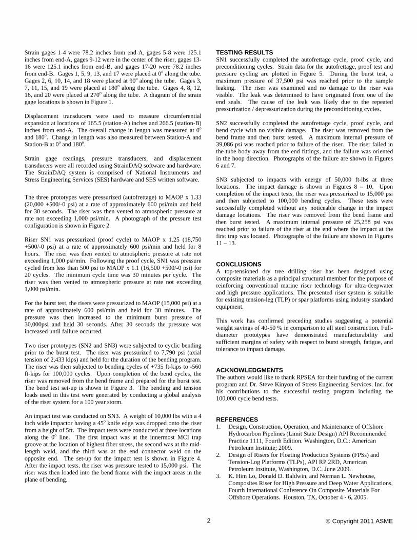
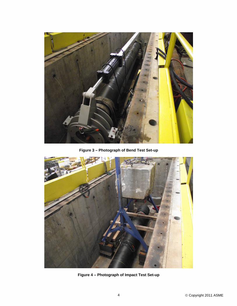
The three prototypes were pressurized (autofrettage) to MAOP x 1.33 (20,000 +500/-0 psi) at a rate of approximately 600 psi/min and held for 30 seconds. The riser was then vented to atmospheric pressure at rate not exceeding 1,000 psi/min. A photograph of the pressure test configuration is shown in Figure 2. Riser SN1 was pressurized (proof cycle) to MAOP x 1.25 (18,750 +500/-0 psi) at a rate of approximately 600 psi/min and held for 8 hours. The riser was then vented to atmospheric pressure at rate not exceeding 1,000 psi/min. Following the proof cycle, SN1 was pressure cycled from less than 500 psi to MAOP x 1.1 (16,500 +500/-0 psi) for 20 cycles. The minimum cycle time was 30 minutes per cycle. The riser was then vented to atmospheric pressure at rate not exceeding 1,000 psi/min. For the burst test, the risers were pressurized to MAOP (15,000 psi) at a rate of approximately 600 psi/min and held for 30 minutes. The pressure was then increased to the minimum burst pressure of 30,000psi and held 30 seconds. After 30 seconds the pressure was increased until failure occurred. Two riser prototypes (SN2 and SN3) were subjected to cyclic bending prior to the burst test. The riser was pressurized to 7,790 psi (axial tension of 2,433 kips) and held for the duration of the bending program. The riser was then subjected to bending cycles of +735 ft-kips to -560 ft-kips for 100,000 cycles. Upon completion of the bend cycles, the riser was removed from the bend frame and prepared for the burst test. The bend test set-up is shown in Figure 3. The bending and tension loads used in this test were generated by conducting a global analysis of the riser system for a 100 year storm. An impact test was conducted on SN3. A weight of 10,000 lbs with a 4 inch wide impactor having a 45o knife edge was dropped onto the riser from a height of 5ft. The impact tests were conducted at three locations along the 0o line. The first impact was at the innermost MCI trap groove at the location of highest fiber stress, the second was at the mid-length weld, and the third was at the end connector weld on the opposite end. The set-up for the impact test is shown in Figure 4. After the impact tests, the riser was pressure tested to 15,000 psi. The riser was then loaded into the bend frame with the impact areas in the plane of bending.
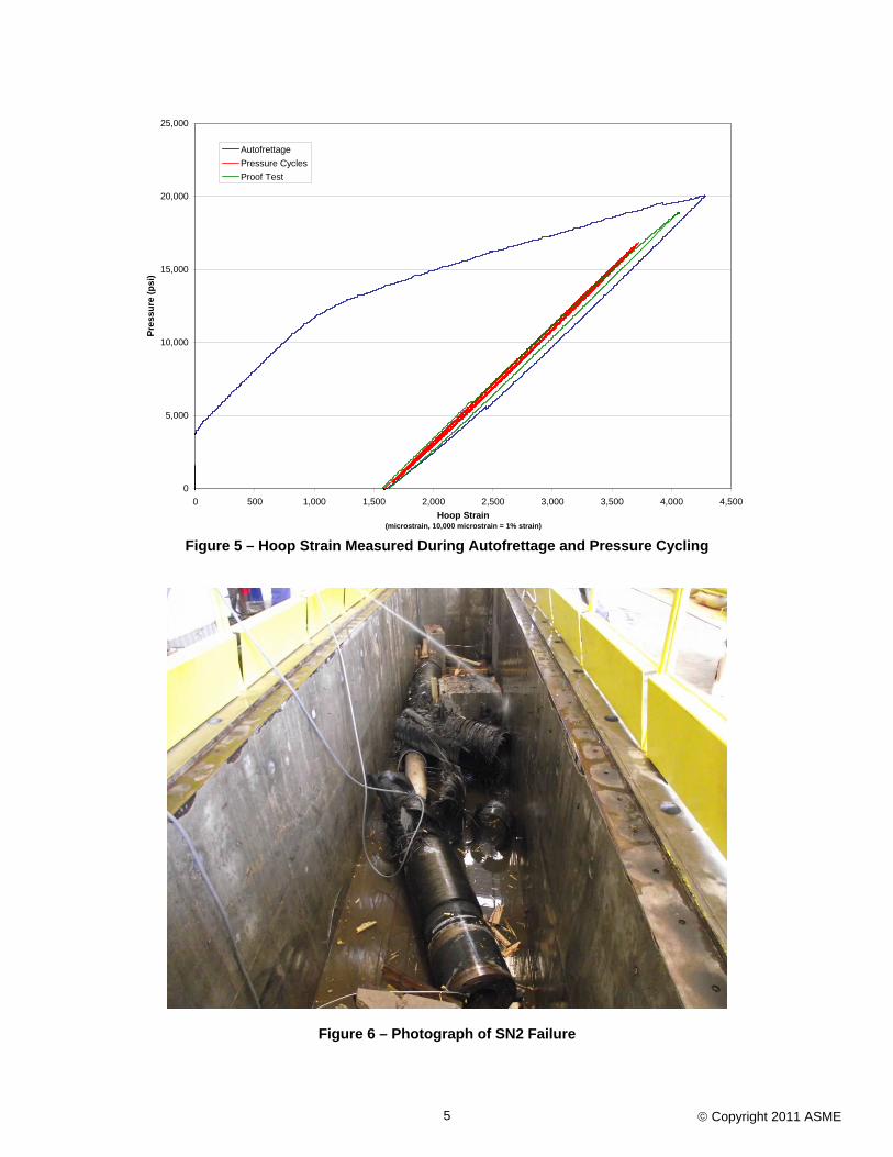
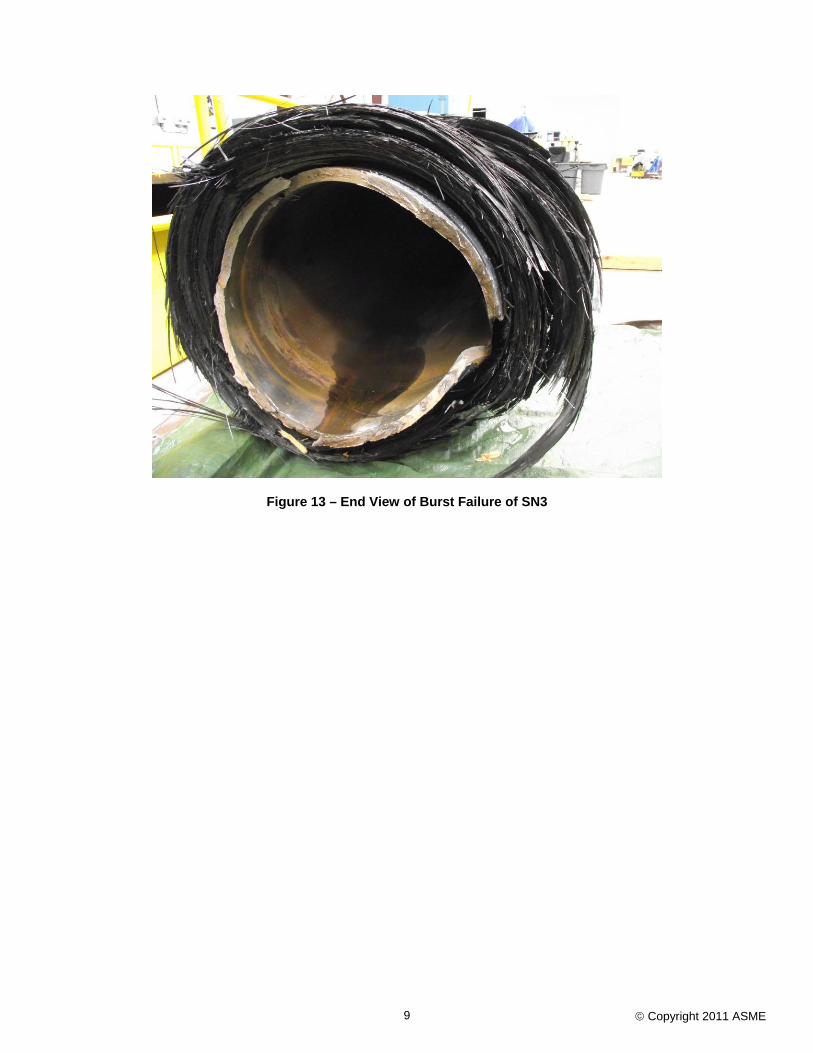
TESTING RESULTS SN1 successfully completed the autofrettage cycle, proof cycle, and preconditioning cycles. Strain data for the autofrettage, proof test and pressure cycling are plotted in Figure 5. During the burst test, a maximum pressure of 37,500 psi was reached prior to the sample leaking. The riser was examined and no damage to the riser was visible. The leak was determined to have originated from one of the end seals. The cause of the leak was likely due to the repeated pressurization / depressurization during the preconditioning cycles. SN2 successfully completed the autofrettage cycle, proof cycle, and bend cycle with no visible damage. The riser was removed from the bend frame and then burst tested. A maximum internal pressure of 39,086 psi was reached prior to failure of the riser. The riser failed in the tube body away from the end fittings, and the failure was oriented in the hoop direction. Photographs of the failure are shown in Figures 6 and 7. SN3 subjected to impacts with energy of 50,000 ft-lbs at three locations. The impact damage is shown in Figures 8 – 10. Upon completion of the impact tests, the riser was pressurized to 15,000 psi and then subjected to 100,000 bending cycles. These tests were successfully completed without any noticeable change in the impact damage locations. The riser was removed from the bend frame and then burst tested. A maximum internal pressure of 25,258 psi was reached prior to failure of the riser at the end where the impact at the first trap was located. Photographs of the failure are shown in Figures 11 – 13. CONCLUSIONS A top-tensioned dry tree drilling riser has been designed using composite materials as a principal structural member for the purpose of reinforcing conventional marine riser technology for ultra-deepwater and high pressure applications. The presented riser system is suitable for existing tension-leg (TLP) or spar platforms using industry standard equipment. This work has confirmed preceding studies suggesting a potential weight savings of 40-50 % in comparison to all steel construction. Full-diameter prototypes have demonstrated manufacturability and sufficient margins of safety with respect to burst strength, fatigue, and tolerance to impact damage. ACKNOWLEDGMENTS The authors would like to thank RPSEA for their funding of the current program and Dr. Steve Kinyon of Stress Engineering Services, Inc. for his contributions to the successful testing program including the 100,000 cycle bend tests. REFERENCES 1. Design, Construction, Operation, and Maintenance of Offshore
Hydrocarbon Pipelines (Limit State Design) API Recommended Practice 1111, Fourth Edition. Washington, D.C.: American Petroleum Institute; 2009.
2. Design of Risers for Floating Production Systems (FPSs) and Tension-Log Platforms (TLPs), API RP 2RD, American Petroleum Institute, Washington, D.C. June 2009.
3. K. Him Lo, Donald D. Baldwin, and Norman L. Newhouse, Composites Riser for High Pressure and Deep Water Applications, Fourth International Conference On Composite Materials For Offshore Operations. Houston, TX, October 4 - 6, 2005.

© Copyright 2011 ASME 3
Figure 1 – Diagram of Strain Gage Locations
Figure 2 – Photograph of Pressure Test Set-up
end-A end-B
Gages 1-4Gages 5-8 Gages 9-12 Gages 13-16
Gages 17-20
Not to Scaleend-A end-B
Gages 1-4Gages 5-8 Gages 9-12 Gages 13-16
Gages 17-20
Not to Scale
© Copyright 2011 ASME 4
Figure 3 – Photograph of Bend Test Set-up
Figure 4 – Photograph of Impact Test Set-up
© Copyright 2011 ASME 5
0
5,000
10,000
15,000
20,000
25,000
0 500 1,000 1,500 2,000 2,500 3,000 3,500 4,000 4,500Hoop Strain
(microstrain, 10,000 microstrain = 1% strain)
Pres
sure
(psi
)AutofrettagePressure CyclesProof Test
Figure 5 – Hoop Strain Measured During Autofrettage and Pressure Cycling
Figure 6 – Photograph of SN2 Failure

© Copyright 2011 ASME 6
Figure 7 – Close-up Photograph of SN2 Failure
Figure 8 – Photograph of Impact Damage at First Trap

© Copyright 2011 ASME 7
Figure 9 – Photograph of Impact Damage at Center Weld Location
Figure 10 – Photograph of Impact Damage at End Connector Weld

© Copyright 2011 ASME 8
Figure 11 – Overall View of Burst Failure of SN3
Figure 12 – Burst Failure of SN3
© Copyright 2011 ASME 9
Figure 13 – End View of Burst Failure of SN3