Embed Size (px)
Citation preview
Abridgment
Analysis of Subgrade Rutting in Flexible Airfield Pavements
Y. T. Chou, Soils and Pavements Laboratory, U.S. Army Engineer Waterways Experiment Station, Vicksburg, Mississippi
The problem of subgrade rutting is an important factor in the overall structural design system of flexible pavements. In recent years the method of controlling the magnitude of the vertical compressive strain at the surface of the subgrade to some tolerable amount associated with a specific number of load repetitions has been proposed and adopted in some design procedures. By controlling the characteristics of the material in the pavement sections through proper design and construe -tion procedures and by ensuring that materials of adequate stiffness and sufficient thickness are used so that this strain level is not exceeded, rutting equal to or less than some prescribed amount is assured. The use of these limiting subgrade strain criteria has been developed for both highway and airfield pavements (!, ; ~ !. ~).
Since most of the c\U·1·ent research work on rutting has emphasized the study of the factors influencing the rutting of subgrade soil by using the i·esults of laboratory repeated-load tests, this paper reports studies in which the amount of rutting occurring in the subgrade soil of prototype accelerated-traffic test pavements has been computed, and the rutting characteristics of subgrade soil as related to factors such as pavement thickness, sl.lbgi-ade strength, magnitude of load, and load repeti tions have been investigated. Compntations we1•e also made on subgrade soils of many pavements designed by the CBR equation for different loads and different subgrade strengths by using the procedure suggested by Monismith and others (~.
LABORATORY TESTING AND THEORETICAL COMPUTATIONS
The soil tested in the laboratory was a heavy clay material, which has an LL of 73 and a PI of 48. The samples were 7.1 cm (2.8 in) in diameter and 15.2 cm (6 in) in length and were compacted using the Corps of
Publication of this paper sponsored by Committee on Strength and Deformation Characteristics of Pavement Sections.
44
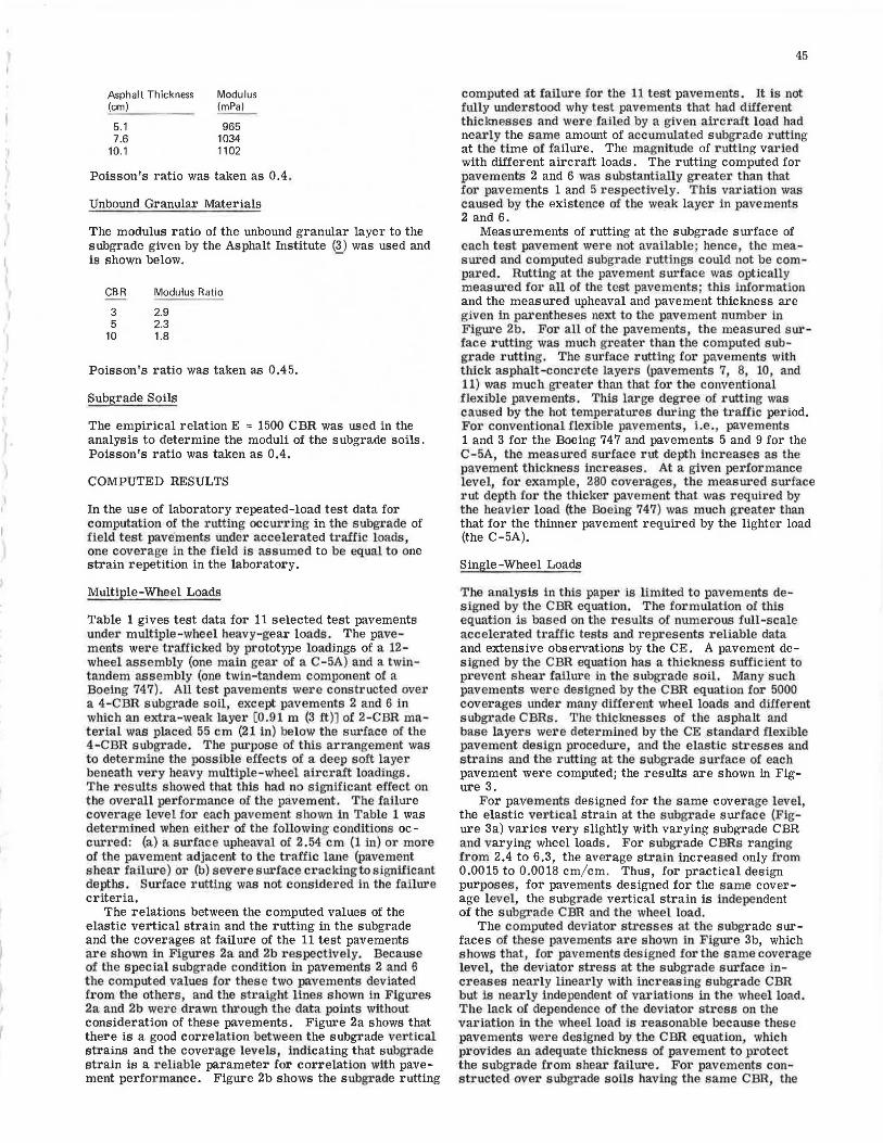
Engineers (CE) 12 compaction effort. A conventional triaxial cell was used for testing, but no confining pressure was used throughout the testing program. The lab r atory results showed that the permanent strain increases greatly with increased load repetitions and also with increased load intensity. As the CBR of the soil increases, its resistance to permanent deformation increases rapidly (7). Elastic strains were measured in each soil specimen during the tests. Figure 1 shows the relation between the elastic and the permanent strains measured at 1000 repetitions. The permanent strain focreases with increasing elastic strain, and, at a given elastic strain, the pe1·manent strain increases with decreasing soil strength. Similar relations are also found for other numbers of strain repetitions.
The BISTRO computer program was used to compute the stresses in the subgrade. The computed points in the subgi·ade we1·e spaced closely nea1· the subgrade surface but farther apart as the depth inc1·eased. The permanent strains were computed to a depth of about 16 m (50 ft), where the stresses became negligibly small. For single-wheel loads, the permanent strains were computed at points along the load axis ; for multiple-wheel loads, the permanent strains were computed at points along the vertical axis at the centroid of the Boeing 747 twin-tandem assembly and at points along the vertical axia u.1.der one of the innel' wheels in the second row of the C-5A 12-wheel assembly, where the computed values are generally their maximum.
The test pavements analyzed in this study were conventional flexible pavements and full-depth asphalt pavements. The selections of modulus values for the asphalt concrete, unbound granular materials, and subgrade soils are explained as follows:
Asphalt Concrete
For each test pavement, a mean temperature versus depth relation for the whole traffic period was determined and used in the computations. The resilient moduli of asphalt mixtw·es developed by the Asphalt Institute (8) and shown below were used. -
Asphalt Thickness (cm)
5.1 7.6
10.1
Modulus (mPa)
965 1034 1102
Poisson's ratio was taken as 0.4.
Unbound Granular Materials
The modulus ratio of the unbound granular layer to the subgrade given by the Asphalt Institute (3) was used and is shown below. -
CBR Modulus Ratio
3 2.9 5 2.3
10 1.8
Poisson's ratio was taken as 0.45.
Subgrade Soils
The empirical relation E = 1500 CBR was used in the analysis to determine the moduli of the subgrade soils. Poisson's ratio was taken as 0.4.
COMPUTED RESULTS
In the use of laboratory repeated-load test data for computation of the rutting occurring in the subgrade of field test pave·ments under accelerated traffic loads, one coverage in the field is assumed to be equal to one strain repetition in the laboratory.
Multiple-Wheel Loads
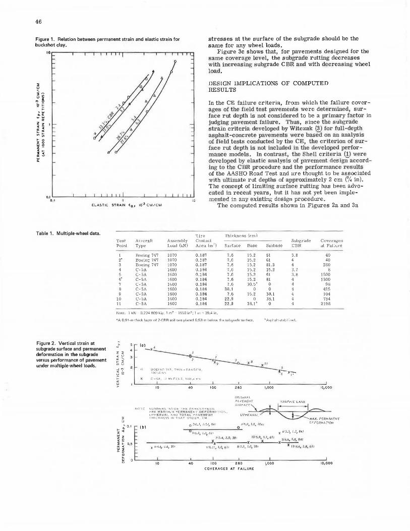
Table 1 gives test data for 11 selected test pavements under multiple-wheel heavy-gear loads. The pavements were trafficked by prototype loadings of a 12-wheel assembly (one main gear of a C-5A) and a twintandem assembly (one twin-tandem component of a Boeing 747). All test pavements were constructed over a 4-CBR subgrade soil, except pavements 2 and 6 in which an extra-weak layer [0 .91 m (3 ft)] of 2-CBR material was placed 55 cm (21 in) below the surface of the 4-CBR subgrade. The purpose of this arrangement was to determine the possible effects of a deep soft layer beneath very heavy multiple-wheel aircraft loadings. The results showed that this had no signnicant effect ou the overall pel'formance of the pavement. The failure coverage level for each pavement shown in Table 1 was determined when either of the following conditions oc -curred: (a) a surface upheaval of 2.54 cm (1 in) or more of the pavement adjacent to the traffic lane (pavement shear failure) 01· (b) severe surfacecrackingto signtticant depths. Surface rutting was not conside1·ed in the failure criteria.
The relations between the computed values of the elastic vertical strain and the rutting in the subgrade and the coverages at failure of the 11 test pavements are shown in Figures 2a and 2b respectively. Because of the special subgrade condition in pavements 2 and 6 the computed values for these two pavements deviated from the others, and the straight lines shown in Figures 2a and 2b were drawn through the data points without consideration of these pavements. Figure 2a shows that there is a good correlation between the subgrade vertical strains and the coverage levels , indicating that subgi'ade strain is a i·eliable parameter for correlation with pavement performance. Figure 2b shows the subgrade rutting
45
computed at failui·e for the 11 test pavements. It is not fully understood why test pavements that had different thicknesses and were failed by a given aircraft load had nearly the same amount of accumulated subgrade rutting at the time of failure. The magnitude of rutting varied with different aircraft loads. The rutting computed for pavements 2 and 6 was substantially greater than that for pavements 1 and 5 respectively. TWs vai·iation was caused by the existence of the weak laye1· in pavements 2 and 6.
Measurements of rutting at the subgrade surface of each test pavement were not available· hence, the measured and computed subgrade ruttings could not be compared. Rutting at the pavement surface was optically measured for all of the test pavements; this information and the measured upheaval and pavement thickness are given in pai·entheses next to the pavement number in Figure 2b. For all of the pavements, the measured surface rutting was much greater than the computed subgrade rutting. The surface rutting for pavements with thick asphalt-concrete layers (pavements 7, 8, 10, and 11) was much greater than that for the conventional flexible pavements. This lai·ge degree of rutting was caused by the hot temperatures during the traffic period. For conventional flexible pavements, i.e., pavements 1 and 3 for the Boeing 747 and pavements 5 and 9 for the C-5A, the measured surface rut depth increases as the pavement thickness increases. At a given performance level, for example, 280 coverages, the measured sul'face rut depth for the thicker pavement that was required by the heavier load {the Boeing 747) was much greater than that for the thinner pavement required by the lighter load (the C-5A).
Single-Wheel Loads
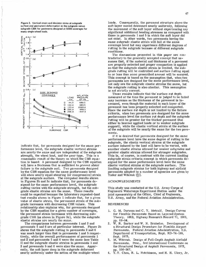
The analysis in this paper is limited to pavements designed by the CBR equation. The formulation of this equation is based on the r esults of nume1·ous full-scale accelerated tnffic tests and represents reliable data and extensive observations by the CE. A pavement designed by the CBR equation has a thickness sufficient to prevent shear failure in the subgrade soil. Many such pavements were designed by the CBR equation for 5000 coverages under many dille1·ent wheel loads and different subgrade CBRs. The thicknesses of the asphalt and base layers were determined by the CE standard flexible pavement design procedure, and the elastic stresses and strains and the i·utting at the subgrade surface of each pavement were computed; the results are shown in Figure 3.
For pavements designed for the same coverage level, the elastic vertical strain at the subgrade surface (Figure 3a) varies very slightly with varying subgrade CBR and varying wheel loads. For subgrade CBRs ranging from 2.4 to 6.3, the average strain. increased only from 0.0015 to 0.0018 cm/ cm. Thus, for practical design purposes, for pavements designed for the same coverage level, the subgrade vertical strain is independent of the subgrade CBR and the wheel load.
The computed deviator stresses at the subgrade surfaces of these pavements are shown in Figure 3b, which shows that, for pavements designed for the same coverage level, the deviato1· stress at the subgrade surface increases nearly linearly with increasing subgrade CBR but is nea1:ly independent of variations in the wheel load. The lack of dependence of the deviator stress on the variation in the wheel load is reasonable because these pavements were designed by the CBR equation, which provides an adequate thickness of pavement to protect the subgrade from shear failure. For pavemen~s constructed over subgrade soils having the same CBR, the
46
Figure 1. Relation between permanent strain and elastic strain for buckshot clay.
stresses at the surface of the subgrade should be the same for any wheel loads.
2 u ' a~
.., 0
\? !: t
' ... .... w ...
0:
! Z I : c t- 0:
"'lii t- 0 z 0 "'0 ~ -2 ~ a: -"' ..
Figure 3c shows that, for pavements designed for the same coverage level, the subgrade rutting decreases with increasing subgrade CBR and with decreasing wheel load.
DESIGN IMPLICATIONS OF COMPUTED RESULTS
In the CE failure criteria, from which the failure coverages of the field test pavements were determined, sur·face rut depth is not considered to be a primary factor in judging pavement failure. Thus, since the subgrade stl'ain criteria developed by Witczak (~) for Lull-depth asphalt-concrete pavements were based on an analysis of field tests condueted by tbe CE, the criterion of surface rut depth is not included in the developed performance models. In contrast, the Shell criteria (1) were developed by elastic analysis of pavement design according to the CBR procedure and the performance results
0,1 .._ _ _ _._ _ ___.. _ _.__..__.___._ ....... ......._ __ _..___.___.___.__.__._ ....... _,
of the AASHO Road Test and are thought to be associated with ultimate rut depths of approximately 2 cm (%in). The concept of limiting surface rutting has been advocated in recent yeru:s, but it has not yet been implemented in any existing design procedure. 0 ,t :c
ELASTIC STRAIN (RI 10·3 CM/CM The computed results shown in Figures 2a and 3a
Table 1. Multiple-wheel data.
Figure 2. Vertical strain at subgrade surface and permanent deformation in the subgrade versus performance of pavement under multiple-wheel loads.
Tire Thickness (cm) Test Aircraft Assembly Contact Subgracte Coverages Point Type Load (kN) Area (m') Sur[ace Base Subbase CBR
1 Boeing 747 1070 0.187 7 .6 15.2 61 3.8 2· Boeing 747 1070 0.1 87 7,6 15.2 61 4 3 Boeing 747 1070 0 .187 7,6 15.2 81.3 4 4 C-5A 1600 0.1 84 7 .6 15.2 15.2 3. 7 5 C-5A 1600 0.104 7.G 15.2 61 3.~ 5• C-5A 1600 0.184 7.6 15.2 61 4 7 C-5A 1600 0.184 7. 6 30.5b 0 4 8 C-5A 1600 0.184 38.1 0 0 4 9 C-5A 1600 0.184 7.6 15.2 38.1 4
10 C-5A 1600 0.184 22.9 0 38.1 4 11 C-5A 1600 0.184 22.9 38.1 b 0 4
Note: 1 kN = 0.224 809 kip; 1 m' = 1550 in'; 1 m = 39.4 in,
•A 0,91 -m thick layer of 2-CBR soil was placed 0 53 m below the subgrade surface. b Asphal t-stabil1zed .
z::; < u .. ' I-::; "'u _J., <' u e 1-.. "' >
4
3 -
(al • -x
~lC1 l ~X· lC IO
0 BOEING 747 TWIN -TANDEM - ~I!_ 1067 .6 KN 6 )(.;;-
)( C-SA , 12 WHEE LS 160 1,'1 KN
10 40 100 280 1,000
ORIGINAL
PAVEMENT TRAFFIC LANE
at Failure
40 40
280 8
1500 1500
98 425 104 734
2198
10,000
NOTE SURFACE'\ ~I • 1,,...--......., UPHEAVAL ~ :AX. PERMANENT
N UMB ERS I NSID E THE PARENTHESIS ARE ~A.X IMUM PERM,i\U(NT 0 F0f1 ... ATION . UPH~VA L AN O TQ"l.A PA\IE MFttT
::; u
.;: 0 I ( b) ~.,
~ Q 2 I- o.s 0: < ~~
0 IL
"' c
THI C KNESS IN THAT ORD ER , C M
O 216,I, 2.541 84J 318.9. 1.8, 1041
~~-------~o,._ h6,r, z.1, B4 •
~t1, <1 , 1.0. JS• UffS,t, f. t, dl f
x 6fJ.J, 1.3, 84)
$1•.6. 1.e, ..,,
DEFORMATION
~----------4x x~-A---x---911. 27, 1.0. ~I J a-1.J, t.o. J"' x 111.t.4, 1.!I. 6H
10 40 100 280 1,000 10,000
COVERAGES AT FAILURE
, I
Figure 3. Vertical strain and deviator stress at subgrade surface and permanent deformation in the subgrade versus subgrade CSR for pavements designed at 5000 coverages for many single-wheel loads.
<ll::; LB _Ju
g ~2.0f (a)
~~ 1.6 ~o ~- I ~ 1·4 2.__ _ __ 3..._ __ _.4 _ __ ..... 5 _ __ ...... 6 __ __,
~ 150 ( b l ~
2
~ 1 00
"' er 1-Vl
er 50 0 ~ > . w O'-----'-----'----'-----'----' a 2 3
::; 0 .8 (c) u
c. <l
z 0
~ 0 ,5 ::; er 0 ... "' a 1-z "' z < ::; er
4
5000 DESIGNED COVERAGES
5
INFLATION LOAD PRESSURE ~ 10 3 PA
0 689.5 0 689.5 2068.4
689.5 1447.9
~ 02~---3'-----'4---'"'5----'6--~
SUBGRADE CBR
indicate that, for pavements designed for the same performance level, the subgrade elastic vertical strains are nearly the same and are independent of the subgrade strength, the wheel load, and the gear type. This is a r easonable result of the theory on which the CBR equation is based: A pavement designed by the CBR equation will have a thickness that is sufficient to prevent shear failure in the subgrade soil. Two pavements designed by the CBR equation for the same performance level will show nearly equal shearing (or compressive) strain at the subgrade surface . The computed results shown in Figures 2b and 3c indicate that, for pavements designed for the same performance level, the subgrade rutting varies with the subgrade strength, but the subgr ade elastic strai11s are the same. These results could be expected because the labo1·atory repeated-load test results shown in Figure 1 indicate that, for a given value of elastic strain, the permanent strain of the subgrade increases with decreasing CBR values. This relationship a.lso explains why, for pavements designed by the CBR equation for a given number of coverages the permanent strain increases with decreasing subgrade CBR (as s)lown in Figure 3c), while the subgi·ade elastic strains are nearly the same.
The comparisons between pavements 1 and 2 and pavements 5 and 6 are of particular interest. Figure 2b shows tllat the subgrade rutting in pavements 2 and 6 was much larger than that in pavements 1 and 5 respectively, while the overall performances of pavements 1 and 2 and pavements 5 and 6 were the same (see Table 1) and the subg1·ade elastic strains in pavements 1 and 2 and pavements 5 and 6 were also the same. Appai·ently, the soft layer deep in the subgrade deformed nearly uniformly unde1· the action of the multiple-wheel
47
loads. Consequently, the pavement structure above the soft layer moved downward neai·ly uniformly, following the movement of the soft layer without experiencing any significant additional bending stresses as compared with those in pavements 1 and 5 in which the soft layer did not exist. In other words, two pavements having the same subgrade elastic strain will fail at the same coverage level but may experience different degrees of rutting in the subgrade because of different subgrade conditions.
The discussions presented in this paper are contradictory to the generally accepted concept that assumes that, if the material and thickness of a pavement are properly selected and proper compaction is applied so that the subgrade elastic strain is limited, the subgrade rutting will be controlled and surface rutting equal to or less than some prescribed amount will be ensu1·ed. This concept is based on the assumption that, when two pavements are designed for the same performance level, not only are the subgrade elastic strains the same, but the subgrade rutting is also similar. This assumption is not strictly correct .
These results indicate that the· surface rut depth measured at the time the pavement is judged to be failed may increase as the thickness of the pavement is increased, even though the material in each layer of the pavement has been properly selected and compacted. Since the surface rut depth is not limited by the failure c,t•iteria, when two pavements are designed for the same performance level the surface rut depth and the subgrade rutting will be greater for the thicker pavement (due either to heavier applied loads or to weaker subgrade support), while the elastic vertical strai11 at the surface of the subgrade will be nearly the same for the two pavements.
If it is desired that pavements designed for the same performance level have the same degree of rutting in the subgrade, the elastic vertical strains at the subgrade su1·face induced by the load will have to be varied with smaller elastic strains allowed for weaker subgrades and greate1• elastic strains allowed Io1· stronger subgrades. This is, of course, in contrast with the cui·rent limiting subgi·ade strain crite1·ia concept in which pavements de signed for the same performance level have the same elastic vertical strains at the subgrade surface. [The limiting subgracle strains for both highway and airfield pavements adopted by a number of agencies are given by Yoder and Witczak (~)).
ACKNOWLEDGMENTS
This study was conducted at the U.S. Army Corps of Engineers Waterways Experiment Station under the joint sponsorship of the Office, Chief of Engineers, U.S. Army, and the Federal Aviation Administration,
REFERENCES
1. G. M. Dorman and C. T. Metcalf. Design Curves for Flexible Pavements Based on Layered System Theory. HRB, Highway Research Record 71, 1965, pp. 69-84.
2. W. R. Barker and W. N. Brabston. Development of a Structural Design Procedure for Flexible Airport Pavements. Federal Aviation Administration, U.S. Department of Transportation, Rept. RD-74-199, Sept. 1975.
3. M. Witczak. Design of Full-Depth Asphalt Airfield Pavements. Proc., 3rd International Conference on the Structural Design of Asphalt Pavements, 1972, pp. 550-567.
4. Y. T. Chou, R. L. Hutchinson, and H. H. Ulery, Jr.
48
Design Method for Flexible Airfield Pavements. TRB, Transportation Research Record 521, 1974, pp. 1-13.
5. E. J. Yoder and M. W. Witczak. Principles of Pavement Design, 2nd Ed. Wiley, New York, 1975, p. 291.
6. C. L. Monismith, N. Ogawa, and C. R. Freeme. Permanent Deformation Characteristics of Subgrade Soils in Repeated Loading. TRB, Trans portation Research Record 537, 1975, pp. 1-7.
7. F. C. Townsend and E . E. Chisolm. Plastic and Resilient Properties of Vicksburg Buckshot Clay Under Repetitive Loadings. U.S. Army Engineer Waterways Experiment Station, Vicksburg, Miss., technical rept., in preparation.
8. R. I. Kingham and B. F . Kallas. Laboratory Fatigue and Its Relationship to Pavement Performance. Proc., 3rd International Conference on the Structural Design of Asphalt Pavements, 1972, pp. 849-865.