Embed Size (px)
Citation preview

Rochester Institute of Technology Rochester Institute of Technology
RIT Scholar Works RIT Scholar Works
Theses
2010
Analysis of compression strength of corrugated shipping Analysis of compression strength of corrugated shipping
containers with different designed hand holes containers with different designed hand holes
Wonho Kwak
Follow this and additional works at: https://scholarworks.rit.edu/theses
Recommended Citation Recommended Citation Kwak, Wonho, "Analysis of compression strength of corrugated shipping containers with different designed hand holes" (2010). Thesis. Rochester Institute of Technology. Accessed from
This Thesis is brought to you for free and open access by RIT Scholar Works. It has been accepted for inclusion in Theses by an authorized administrator of RIT Scholar Works. For more information, please contact [email protected].

ANALYSIS OF COMPRESSION STRENGTH OF CORRUGATED SHIPPING
CONTAINERS WITH DIFFERENT DESIGNED HAND HOLES
By
Wonho Kwak
A thesis
Submitted to
Department of Packaging Science
College of Applied Science and Technology
Rochester Institute of Technology
Rochester, New York
in partial fulfillment of the requirements
for the degree of
MASTER OF SCIENCE
2010


I
Department of Packaging Science
College of Applied Science and Technology
Rochester Institute of Technology
Rochester, New York
CERTIFICATE OF APPROVAL
M.S. DEGREE THESIS
The M.S. degree thesis of
Wonho Kwak
Has been examined and approved
By the thesis committee as satisfactory
For the thesis requirements for the
Master of Science degree
Daniel L. Goodwin ______________________________________
Thomas Kausch ______________________________________
Deanna M. Jacobs ______________________________________
II
ANALYSIS OF COMPRESSION STRENGTH OF CORRUGATED SHIPPING
CONTAINERS WITH DIFFERENT DESIGNED HAND HOLES
I, Wonho Kwak, hereby grant permission to the Wallace
Memorial Library of Rochester Institute of Technology to
reproduce me thesis in whole or in part. Any reproduction
will not be for commercial use or profit.
June 30, 2010

III
ACKNOWLEDGEMENTS
There have been a lot of people who have supported and
contributed to this study. I am truly thanks to each of
them for their encouragement.
I thank to my thesis advisor Dr. Daniel L. Goodwin for his
patient guidance and advice. I also appreciate to the
committee member who Professor Thomas Kausch for his
assistance and reviews.
My sincere appreciation goes to Packaging Science Master
Program chair professor Deanna M. Jacobs for her
deliberation of all my thesis procedure.
I specially thank to my family, my father, mother and wife.
Without their support, this thesis would not have been
possible to complete.

IV
ABSTRACT
Analysis of compression strength of corrugated shipping
containers with different designed hand holes
BY
WON HO KWAK
2010
The purpose of this study was to examine the compression
strength of the corrugated shipping containers having the
conventional purpose hand holes and the arc top hand holes.
Generally, the arc top hand hole has stronger tear strength
than the conventional purpose hand hole, but the arc top
hand hole has a larger opening area than the conventional
purpose hand hole, and the larger opening area needs more
space of a dispersion of compression stress to increase
compression resistance. However, when a hand hole has
enough space to distribute compression stress, the only one
variable is the width of the opening area in shipping
containers if the containers have the same dimensions.
In this study, two designs of the hand hole have the same
width of opening area and are located to have enough space
to distribute compression stress. As a result, the
resistance forces of containers are the same in each
different environment.

V
Table of Contents
CERTIFICATE OF APPROVAL ............................................................................................. I
THESIS RELEASE PERMISSION ...................................................................................... II
ACKNOWLEDGMENTS ............................................................................................................... III
ABSTRACT.................................................................................................................................. IV
LIST OF FIGURES ............................................................................................................ VIII
LIST OF TABLES .................................................................................................................... X
LIST OF GRAPHS .................................................................................................................. XI
1.0 Introduction...........................................1
1.1 Problem Statement ....................................3
1.2 Hypotheses ...........................................8
1.3 Assumptions ..........................................9
2.0 Literature review.....................................11
2.1 Introduction of Packaging ...........................11
2.2 Corrugated board ....................................12
2.2.1 Flute standards and Corrugated board grades....12
2.3 Corrugated shipping container .......................13
2.3.1 Styles of corrugated containers ...............14
2.3.2 Compression Strength of corrugated containers..17
2.4 Testing for corrugated material .....................18
2.4.1 BCT method ....................................18
2.4.2 McKee‟s Formula ...............................19

VI
2.5 Holes on corrugated shipping containers .............21
2.6 Environments of distribution ........................23
3.0 Design of experiment .................................29
3.1 Equipment ...........................................29
3.1.1 Compression tester ............................29
3.1.2 Sample cutting table ..........................32
3.1.3 Environment chamber ...........................34
3.1.4 Computer based design system ..................36
3.2 Sample designs .....................................38
3.3 Test method .........................................38
3.3.1 Pre-conditioning ..............................39
3.3.2 Conditioning ..................................39
3.3.3 Test procedure.................................42
4.0 Data and results .....................................45
4.1 Data ................................................45
4.2 Data analysis .......................................45
4.2.1 Room conditions ...............................45
4.2.2 Hot and humid Conditions.......................47
4.2.3 Cold and humid conditions......................48
5.0 Conclusion ...........................................51
6.0 Recommendations ......................................54
7.0 Appendix A ...........................................55
8.0 Appendix B ...........................................61

VII
9.0 Appendix C (BCT test results).........................68
10.0 Works Cited .........................................74

VIII
List of Figures
Page
(Figure 1) 10”x10”x10” ‘C’ flute RSC corrugated box sample.
...................................................... 4
(Figure 2) 10”x10”x10” ‘C’ flute RSC corrugated box sample
with 1”x4” own designed hand hole. .................... 4
(Figure 3) Load of compression strength................... 6
(Figure 4) Load of compression strength with hand hole.... 7
(Figure 5) Minimum space of distributing compression
strength. ............................................. 8
(Figure 6) Models for various ventilation holes
investigated ......................................... 22
(Figure 7) Rate of compression strength of various
ventilation hole types. .............................. 22
(Figure 8) Compression strength tester................... 31
(Figure 9) Ending position of compression strength tester 32
(Figure 10) Sample cutting table......................... 33
(Figure 11) Control unit of sample cutting table......... 34
(Figure 12) Environmental chamber........................ 35
(Figure 13) Control box of environmental chamber......... 36
(Figure 14) Computer Aided Design system (Artios CAD).... 37
(Figure B- 1) Conditioning table <ISTA 2A 2008 – Page 6>. 61
(Figure B- 2) 72hours graph for cold and humid
conditioning. ........................................ 62
(Figure B- 3) 72hours graph for hot and humid conditioning.
..................................................... 62
(Figure B- 4) Conventional purpose hand hole sample design.
..................................................... 63

IX
(Figure B- 5) Conventional purpose hand hole sample design.
..................................................... 64
(Figure B- 6) Arc-top hand hole sample design............ 65
(Figure B- 7) Box sample design having arc-top hand hole. 66
(Figure B- 8) Constant rate control configuration........ 67
X
List of Tables
Page
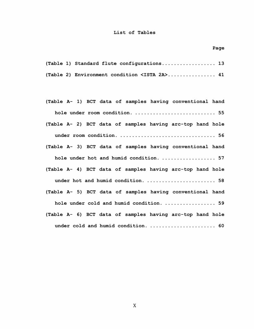
(Table 1) Standard flute configurations.................. 13
(Table 2) Environment condition <ISTA 2A>................ 41
(Table A- 1) BCT data of samples having conventional hand
hole under room condition. ........................... 55
(Table A- 2) BCT data of samples having arc-top hand hole
under room condition. ................................ 56
(Table A- 3) BCT data of samples having conventional hand
hole under hot and humid condition. .................. 57
(Table A- 4) BCT data of samples having arc-top hand hole
under hot and humid condition. ....................... 58
(Table A- 5) BCT data of samples having conventional hand
hole under cold and humid condition. ................. 59
(Table A- 6) BCT data of samples having arc-top hand hole
under cold and humid condition. ...................... 60

XI
List of Graphs
Page
(Graph 1) Comparison compression strength under room
temperature. ......................................... 46
(Graph 2) Comparison compression strength under hot and
humid. ............................................... 48
(Graph 3) Comparison compression strength under cold and
humid. ............................................... 50
(Graph A- 1) Compression strength of samples having
conventional hand hole under room conditions. ........ 55
(Graph A- 2) Compression strength of samples having arc-top
hand hole under room conditions. ..................... 56
(Graph A- 3) Compression strength of samples having
conventional hand hole under hot and humid conditions. 57
(Graph A- 4) Compression strength of samples having arc-top
hand hole under hot and humid conditions. ............ 58
(Graph A- 5) Compression strength of samples having
conventional hand hole under cold and humid conditions.
..................................................... 59
(Graph A- 6) Compression strength of samples having arc-top
hand hole under cold and humid conditions. ........... 60

XII
(Graph C- 1) BCT data of sample having conventional hand-
hole under room conditions <Sample Graph 1> .......... 68
(Graph C- 2) BCT data of sample having arc top hand-hole
under room conditions <Sample Graph 2> ............... 69
(Graph C- 3) BCT data of sample having arc top hand-
hole under hot and humid conditions <Sample Graph 3> . 70
(Graph C- 4) BCT data of sample having conventional hand-
hole under hot and humid conditions <Sample Graph 4> . 71
(Graph C- 5) BCT data of sample having conventional hand-
hole under cold and humid conditions <Sample Graph 5> 72
(Graph C- 6) BCT data of sample having arc top hand-hole
under cold and humid conditions <Sample Graph 6> ..... 73

1
1.0 Introduction
Packaging is a means of ensuring safe delivery of a
product to the ultimate user in a sound condition, at a
minimum overall cost (Corrugated Board Packaging, 1993).
Jay Singh, Eric Olsen, S.P. Singh, J. Manley, and F.
Wallace explain in “The effect of ventilation and hand
holes on loss of compression strength in corrugated
boxes” why studying corrugated shipping containers is
important (Journal of Applied Packaging Research 2.4,
2008). Corrugated fiberboard is an efficient and
economical material for making shipping containers that
are widely used for distribution, transportation and
storage of products. Corrugated fiberboard is used to
package about 90% of all products for retail distribution
in the United States.
Corrugated shipping containers are designed to protect
the product from hazards of the distribution,
transportation and storage environment so that the
product can be shipped to consumers without damage. This
meets the manufacturer‟s condition.
In addition, some of corrugated shipping containers
have hand holes because they increase performance of
manual transportation function. The first concern in the
process to make hand holes is the strength of hand holes

2
to hold the weight of contents. Therefore, designers make
an effort to develop new shapes to increase tear strength.
However, the hand holes also affect the compression
strength of corrugated containers during storage and
distribution.
ASTM 6804, which is the “Standard Guide for Hand Hole
Design in Corrugated Boxes,” provides a guide for
designing hand holes with increasing tear strength.
This thesis project evaluates the compression strength
of corrugated boxes with two different common holes which
are introduced in ASTM 6804, named “Conventional purpose
hand hole” (Figure B-5) and “Arc-top hand hole” (Figure
B-7). The arc-top hand hole offers greater tear out
resistance following ASTM 6804. However, the arc-top hand
hole needs more opening area than the conventional
purpose hand hole. It is generally considered that the
compression strength of corrugated shipping containers
with the arc-top hand hole is less than that which occurs
with the conventional purpose hand hole. This study
verifies the compression strength of corrugated shipping
containers with the arc-top hand hole and the
conventional purpose hand hole.

3
The compression strength was tested in three different
humidity and temperature environments to consider
multiple environments.
1.1 Problem statement
A pre-test showed that the hand holes decreased
the compression strength of the corrugated shipping
container. The peak force compression strength of
the corrugated shipping container without hand holes
was 822.4 lbs (Figure 1) and the peak force of
compression strength of the corrugated box with hand
holes sized 1”x4” was 511.9 lbs (Figure 2) –
specimens were made by „C‟ flute corrugated board
and RSC (Regular Slotted Container, p.14) style
corrugated shipping containers. The inside
dimensions were 10”x10”x10” and the samples were
placed in ambient room conditions (temperature was
68.4F and humidity was 62%)for 72 hours before the
test.

4
(Figure 1) 10”x10”x10” ‘C’ flute RSC corrugated box sample.
(Figure 2) 10”x10”x10” ‘C’ flute RSC corrugated box sample
with 1”x4” own designed hand hole.

5
The compression strength of the RSC style corrugated
shipping container is calculated using the McKee
formula and it shows the relationship of compression
strength and the dimension of the box, which is the
perimeter of the corrugated shipping container.
However, the McKee formula does not show the
relationship between the opening areas, such as hand
holes or vent holes1, and the compression strength
because the compression load intensity is not the same
on all points of the perimeter, so a location of hand
holes also has an effect on compression strength
(Figure 3).
1 Hole for the ventilation to keep fresh environment in a shipping container.

6
(Figure 3) Load of compression strength.
However, it is possible to apply the McKee formula
to compare the compression strength of boxes with hand
holes having enough space for dispersion. In
determining the compression strength of the RSC
(Regular Slotted Container) style corrugated container,
the perimeter of the shipping container is the only
variable in the McKee Formula when the same materials
are used. The compression strength of the RSC style

7
shipping containers with hand holes can be estimated
by subtracting the width of the hand holes from the
perimeter of the container if the hand holes are
located in the same position (Figure 4).
(Figure 4) Load of compression strength with hand hole.
If boxes have holes with the same area but
differently designed shape and location, the
compression strength will be different. One study
tested compression strength with different vent hole
designs using a simulation program. The result of the
test also showed different compression strength.

8
However, a problem with this test was that it was
not concerned about strength dispersion space. Figure
5 shows the compression stress around the hand holes.
If the hole does not have enough space horizontally
and vertically around it for distributing the
compression stress, the compression strength is lower
than that of other designs. If the hole has enough
space, the width of the hole is the only variable that
will affect compression strength.
(Figure 5) Minimum space of distributing compression
strength.
1.2 Hypotheses
The height and shape of hand holes are not major
factors affecting compression strength. The width of
the hand hole subtracted from the perimeter of the

9
shipping container is the major factor in reduction of
compression strength.
Even though the arc-top hand hole needs a larger
opening area compared with the conventional purpose
hand hole, the compression strength of corrugated
shipping containers are equal if the width of the hand
holes are the same and have enough space for
distributing compression strength.
1) Hand holes on the shipping container affect the
compression strength of the corrugated shipping box.
2) The height of the hand hole does not affect the
compression strength of the corrugated shipping box.
3) If the corrugated shipping boxes have different hand
holes but the width of the hand holes are same, the
compression strength will be the same.
4) It shows the same result under different conditions,
temperature and humidity.
1.3 Assumptions
1) The materials used for the test have the same
specification and pre-conditioning.
2) The test machines used for the test have the same
performance.

10
3) The compression tester‟s applied forces to the samples
are the same for all configurations.
4) Each type of sample is to be put under three different
conditions and tested at the end of 72 hours. All the
tests are performed in the same conditions during each
test.

11
2.0 Literature review
2.1 Introduction of Packaging
Packaging is a means of ensuring safe delivery of a
product to the ultimate user in a sound condition, at
a minimum overall cost (Corrugated Board Packaging,
1993). This basic meaning of packaging explains the
function of all packaging. The basic function of all
packaging is to identify the product and carry it
safely through the distribution system to the final
user (The Packaging User‟s hand book,1991).
Packaging provides an economical way of protecting
products during distribution. If the packaging is also
adapted to the distribution system and is considered
an integral part of both internal and external
distribution, it is possible to minimize distribution
cost (Corrugated Board Packaging, 1993). As a result,
all packaging has to be designed to protect products
and to reduce materials and then tested to prove
having enough performance.

12
2.2 Corrugated board
Corrugated fiberboard is the most common
distribution container material. Corrugated board has
a sandwich material structure. It comprises a central
paper (called the corrugating medium, or, simply the
„medium‟) which has been formed, using heat, moisture
and pressure, in a corrugated, i.e. fluted, shape on a
corrugator and one or two flat papers (called liners)
have been glued to the tips of the corrugations. The
sandwich can be formed in several ways (Paper and
Paperboard Packaging Technology, 2005).
2.2.1 Flute Standards and Corrugated Board Grades
Corrugated board is normally made in one of the
nine flute sizes which are A, B, C, D, E, F, G, K
and O. However, A, B, C and E flute are commonly
used for industry and properties are below:

13
Flute Flutes/Metre Flutes/Foot Thickness*
Take-up
Factor
A 100 to 120 30 to 36
4.67 (0.184
in.)
1.54 in.
B 145 to 165 44 to 50
2.46 (0.097
in.)
1.32 in.
C 120 to 140 36 to 42
3.63 (0.142
in.)
1.42 in.
E 280 to 310 86 to 94
1.19 (0.047
in.)
1.27 in.
(Table 1) Standard flute configurations
*Not including facing
(Source : ASTM D 5639, Selection of Corrugated
Fiberboard materials and Box Construction Based on
Performance Requirements.)
2.3 Corrugated shipping containers
Corrugated shipping containers were used almost
hundred years ago and these have become the most
popular shipping containers in the world.
Shipping containers exist to serve the needs of
logistical systems. For most of the 20th century, they
have been designed to meet requirements published by

14
the railroad and trucking associations for specific
grades of corrugated fiberboard, based on bursting of
edge-crush test (ECT) strength.
Integration of supply chains and advances in
packaging technology has enlarged the focus to a more
system-wide approach, beyond just transport and simple
properties of corrugated fiberboard.
Since ECT and its relationship to compression and
stacking strength plays a key role in corrugated
fiberboard container performance (Cartons, crates and
corrugated Board, 2005).
2.3.1 Styles of corrugated containers
There are a lot of corrugated boxes with
different styles and some common style of boxes
are introduced below:
a. 0200 Half Slotted Container (HSC)
It is same as Regular Slotted Container (0201)
without one set of flaps.

15
b. 0201 Regular Slotted Container (RSC)
All flaps have the same length, and the two outer
flaps are one-half the container‟s width, so that
they meet at the center of the box when folded.
c. 0202 Overlap Slotted Container (OSC)

16
All flaps have the same length. The outer flaps
overlap by one inch or more.
d. 0203 Full Overlap Slotted Container (FOL)
All flaps have the same length (the width of the
box).

17
e. 0204 Center Special Slotted Container (CSSC)
Inner and outer flaps are cut to different
lengths. Both pairs of flaps meet at the center of
the box.
(Fibre Box handbook, 1999)
2.3.2 Compression Strength of corrugated
containers
BusinessDictionary.com defines compression
strength as Stacking strength of a fiberboard
container measured as the maximum load that can
be applied to it under specified conditions
before it is crushed, and expressed in newtons or
pounds per square inch. Printing directly onto
the container face or surface reduces its
compression strength by crushing the material and

18
saturating the fibers with ink. Also the
compression strength called compression
resistance, compressive strength, or crush
resistance.
2.4 Testing for Corrugated material
The compression strength of a corrugated board box
is a direct measure of the stacking strength of
corrugated board packages, but since the load-bearing
properties of a box are often of decisive importance
under modern transport conditions, it can also be said
that the compression strength constitutes a general
measure of the performance potential of a corrugated
board package. The compression strength is measured
according to some standardized test method which is,
in general, designated the BCT, Box Compression Test,
value (Testing Methods and Instruments for Corrugated
Board, 1992).
2.4.1 BCT method
The BCT-method is only top to bottom load test,
which is, as a rule, carried out on empty sealed
corrugated board shipping containers. These are
compressed between flat parallel plates in a

19
compression tester at a constant compression rate
(Figure B-8).
2.4.2 McKee’s formula
McKee R. C. (1963) published what has become
the industry‟s seminal article in box compression
analysis, including detailed citations of the
literature that preceded their analysis. Their
work resulted in an equation to predict single-
wall box compression strength P, called simply
the “McKee equation,”
121)( bbyxm
b ZDDaPP (1)
where mP is the edge-crush value of the combined
board, xD and yD are the flexural stiffness values
for the combined board in each direction, and Z
is the perimeter of the box to be modeled (Box
Compression Analysis of World-Wide Data Spanning
46 Years, 2005).
According to the McKee equation, the
compression strength BCT of a corrugated board

20
box with the regular Slotted Box (RSC) design can
be predicted from knowledge of:
1. The edgewise crush resistance of the
corrugated board, the ECT-value in kN/m
2. The bending stiffness in the machine and
cross-machine directions of the corrugated board,
MDSB and CDSB , in Nm
3. The periphery of the box, Z in m.
In general, the so-called McKee formula says
121 bbb ZSECTkBCT (2)
The formula can, for corrugated board, be adapted
to
5.025.075.0 ZSBECTkBCT (3)
where SB is the geometric mean stiffness
given by CDMD SBSBSB
k represents constants chosen so that the
product gives the BCT-strength in N (Testing
Method and Instruments for Corrugated Board,
1988, p.11).

21
2.5 Holes in corrugated shipping containers
There are generally two kinds of holes on corrugated
shipping container: vent holes and hand holes.
The vent hole exists for circulation of fresh air
and keeps the temperature stable, and the hand hole
makes a corrugated shipping container easy to carry. A
recent trend in the physical distribution of fresh
food produce requires a somewhat excessive multi-layer
stacking of outer containers within a cold-chain
distribution system. The outer containers with
reasonable compression strength, despite having a
couple of ventilating or hand hole structures, may be
a primary concern in the development of those
containers (Finite Element Analysis of Vent/Hand Hole
Designs for Corrugated Fibreboard Boxes, 2007).
This study used two kinds hand hole for comparing
compression strength. Two hand holes are of different
design and different opening size but the same as sums
of horizontal lengths in the opening areas.

22
(Figure 6) Models for various ventilation holes
investigated
(Figure 7) Rate of compression strength of various
ventilation hole types.

23
Above data showed that type #01, #02, #03, #08, #09,
#11, #13 have the same width of the vent hole and #10
has the smallest width. #02, #03. #10 samples did not
have enough space for distributing compression stress;
therefore, these showed a lower compression strength
than #01, #08, #09, #11, #13.
2.6 Distribution environments
The first step in designing an effective package
system is to determine the severity of the shipping
environment. Evaluation of the product‟s distribution
method can determine which hazards the product will
likely come across, as well as the level of intensity
of those hazards. Then the package system can be
designed accordingly.
Package handling, transportation, and storage can
lead to a variety of hazards within the shipping
environment, including, but not limited to, vertical
drops, horizontal impacts, vehicle vibration,
temperature extremes, and compression loads. The
method of distribution greatly influences the presence
and severity of these hazards, so understanding the
shipping environment is essential to designing a

24
package that will effectively protect its product.
There are four different ways of determining the
environment through which a product is shipped:
- Observation
The most informative method of describing the
distribution environment would be to actually follow a
package as it travels through the shipping environment
and watch what happens to it. Through the use of human
observation, first-hand knowledge of the environment
can be obtained. Cameras can provide documented
evidence of the hazards that a package encounters. Of
course, following a package through its complete
travel route can be very time-consuming and expensive.
The information acquired will only be relevant to the
time the observation was made and will only provide a
glimpse of that environment. In addition, the behavior
of the handlers may be affected by the presence of the
observers, as it is human nature to try to perform
better while being watched.
Unless the observation can take place unnoticed, the
results may not give a completely accurate description
of the shipping environment. This method may work best
for an initial assessment of the environment, which

25
can later be correlated with supporting data gained
from other types of measurement. It may also work well
for simple and/or controlled environments that only
utilize one or two different modes of distribution.
- Damage Claims
Some hazards in a distribution environment go
unnoticed until they cause damage to products with
insufficient protection. A review of damage reports,
which can be obtained from carrier logs, customer
complaints, or shipping department personnel, can
provide a better understanding of the hazards
encountered in a shipping environment. These reports
can be used as documented evidence and can indicate
how much money is lost due to damage in transit. It
may be possible to characterize the type of damage, as
well as the geographical location where the damage
took place.
However, damage reports do not always contain
specific information on the type or extent of damage
that occurred. Sometimes damage is incorrectly blamed
on insufficient packaging, when in fact the product
itself was defective before shipping or the package
was grossly mishandled during shipment. Faulty

26
products are often incorrectly packaged for return,
resulting in damage during shipping that is unrelated
to, or compounds, the original problem. This often
causes damage reports to be misleading. Furthermore,
not all damage is reported, since sometimes losses are
absorbed rather than claimed, making accurate
information hard to obtain.
It can be costly to wait for damage to be reported
before trying to determine its cause. This method is
most effective when investigating damage that occurs
to new products and when trying to improve existing
package systems.
- Literature Search
Perhaps the most widely used approach is to research
what others have done. There have been numerous
studies performed and an examination of available data
can provide a broad understanding of the issues
surrounding the measurement of a distribution
environment. Research also requires a smaller
commitment of time and resources than actually
performing the experiments. The difficulty with this
approach is that the data can sometimes be outdated
and sampling parameters can be unclear or unknown.

27
Conclusions drawn by studies are usually dependent on
the author‟s perspective and selective data may have
been used. Also, the data may not be relevant to the
shipping environment in question and some variables
may not have been fully addressed. In general,
however, this approach has provided the guidelines and
rules of thumb used in today‟s package design work.
- Direct Measurement
The best substitute for actual observation of the
environment a package travels through is the use of a
recording device to monitor the package and/or vehicle
during shipment. The measurement device can record the
events that happen throughout the trip without
influencing the package‟s treatment, since it is
usually concealed inside the package. It can be
calibrated in the lab before use to test for accuracy,
and a correction factor can be established if
necessary. Many devices can collect various types of
measurements at the same time, thereby utilizing the
full capacity of limited resources. Provided the same
route is measured enough times using the same
equipment and protocol, some sort of statistically
valid information can be obtained to help describe

28
that particular channel of distribution. Specific
events will obviously vary from trip to trip but a
general idea of what to expect will develop.
The disadvantages to this technique are that the
equipment can be expensive, and the analysis of the
data very time-consuming. The analysis is also subject
to the limitations of the recording devices. The
accuracy of the equipment determines how well the
recorded event correlates to the actual event, and
sometimes it can be difficult to compare data. Also,
there may be such a great number of variables that
only a rough estimate of the environment can be made.
Although it is not ideal, for now direct measurement
may be the best-suited approach for gaining
information about a specific distribution channel
(Four ways to define the environment distribution,
Hewlett Packard Packaging department, 2004).
29
3.0 Design of experiment
3.1 Equipment
The equipment used for the project are a compression
tester (Lansmont‟s model 152 compression test system),
a sample cutting table (Data TECHnology model DT6646
counter cutter/sample maker), an environmental chamber
(Bally environmental chamber assembly), and a computer
based design system (Artios CAD). All equipment is
located in Packaging Science Department of Rochester
Institute of Technology.
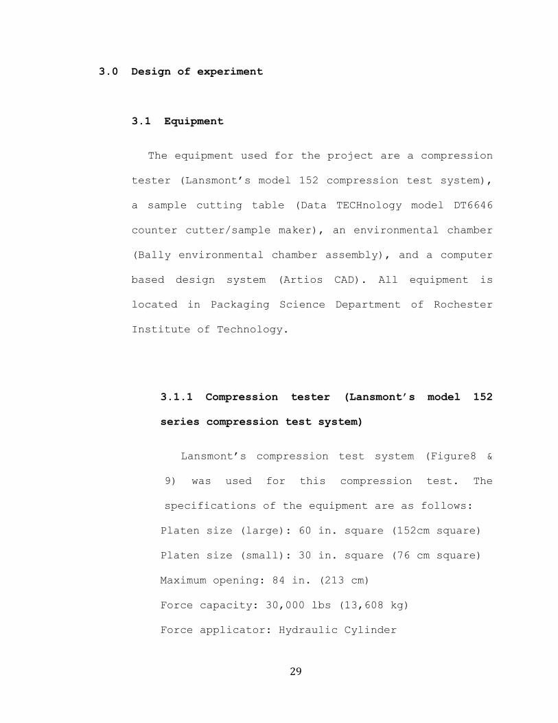
3.1.1 Compression tester (Lansmont’s model 152
series compression test system)
Lansmont‟s compression test system (Figure8 &
9) was used for this compression test. The
specifications of the equipment are as follows:
Platen size (large): 60 in. square (152cm square)
Platen size (small): 30 in. square (76 cm square)
Maximum opening: 84 in. (213 cm)
Force capacity: 30,000 lbs (13,608 kg)
Force applicator: Hydraulic Cylinder

30
Cross-Head positioning: Electric Hoist @ 8
ft./min. (244 cm/min.)
Test speed :0.5 in./min. (1.27 cm/min)
Lansmont‟s Model 152 Compression Test System is
specifically designed to efficiently and
accurately evaluate the performance of individual
packages, pallets, and unit loads under
compressive forces (Http://www.Lansmont.com).
A condition for carrying out the BCT-test in an
accurate and uniform way is that the compression
tester meets the basic requirements specified in
the test standard. These requirements are fixed
so that different test conditions, which may
influence the result, will be kept under control
as much as possible. This is essential if the
test results are to be comparable regardless of
where the test has been carried out. Some of the
requirements given in the standards concern the
design of the compression plates. These shall be
plane and rigid.
Another requirement is a fixed compression
speed, specified to be 0.1 in./min. (10-

31
13mm/min.) (Testing Methods and Instruments for
Corrugated Board, 1988)
(Figure 8) Compression strength tester

32
(Figure 9) Ending position of compression strength tester
3.1.2 Sample cutting table (Data TECHnology model
DT6646 counter cutter/sample maker)
DT6646 counter cutter/sample maker (Figure 10)
is a heavy-duty production counter cutter that
turns into a high-speed sample maker with a quick
tool head change. It is used for cutting sample
containers that are designed by computer based
design systems and the samples are used for

33
verifying design, performance or small amounts of
products. This machine is not a fast method to
make a product, but it can produce a much more
accurate product than producing by hand, and the
cutting unit is manually located using control
unit (Figure 11). The sample cutting table, used
for this study, is model DT6646 made by Data
TECHnology.
(Figure 10) Sample cutting table

34
(Figure 11) Control unit of sample cutting table
3.1.3 Environmental chamber (Bally environmental
chamber assembly)
An environmental chamber (Figure 12) can
control temperature and humidity. It can

35
artificially make a common distribution
environment or extreme distribution environment.
This test used three conditions: room conditions,
low temperature with humidity and high
temperature with humidity because moisture can
easily affect the compression strength of the
corrugated board during distribution. The
artificial environment is recorded during the
test in data sheet in the control box (Figure
13).
(Figure 12) Environmental chamber

36
(Figure 13) Control box of environmental chamber
3.1.4 Computer based design system (ArtiosCAD)
There are many computer based design system in
engineering field such as AutoCAD, CADian and
CivilVad. AutoCAD is a basic design program,
ArchiCAD is used for architectural field
materials. CADian is used for mechanical field,
and CivilCAD is used for Civil Engineering.

37
Artios Corporation made ArtiosCAD specifically
for the packaging science field. This program
allows the designer to pick the material and
common style of container, and easily modify the
design. The designer can send the design to the
cutting table machine to produce sample.
(Figure 14) Computer Aided Design system (Artios CAD)

38
3.2 Sample designs
The RSC style containers with two types of hand
holes were used in the compression test. The
specifications of the corrugated fiberboard are as
follows:
Flute construction: C-Flute
Outer liner: Unbleached kraft
Inner liner: Unbleached kraft
Dimensions (outer): 10”X12”X10” (LXWXD)
- Conventional purpose hand hole (Figure B-6)
Removed area: 3.29 sq inches
Width of hand hole: 3.5 inches
- Arc-top hand hole (Figure B-8)
Removed area: 5.41 sq inches
Width of hand hole: 3.56 inches
3.3 Test method
The test used „C‟ flute corrugated fiberboard to
make samples under three different conditions which
followed ISTA 2A as below 3.3.2. The test procedure
followed ASTM D 642 which is the „Standard Method of

39
Determining Compressive Resistance of shipping
Container components of Unit Loads‟
3.3.1 Preconditioning
The ISTA 2A shows guidelines for
preconditioning for testing. The packaged-product
should be stored prior to climate conditioning at
laboratory ambient temperature and humidity for
six hours. All materials used for the study are
stored under the same condition which is the
laboratory condition ,67.2F and 58% humidity, for
a six hours, so all materials‟ conditions were
the same.
3.3.2 Conditioning
To permit an adequate determination of a
packaged product performance at anticipated
atmospheric limits, and where it is known that
the atmospheric extremes are detrimental to the
product, ISTA:
- Requires the highest temperature and humidity
limits of the product be used, but

40
- Recommends that both the highest and lowest
atmospheric conditions be used.
Condition packaged-products according to one or
more of the conditions listed in the table below:
Anticipated
conditions
Time in
Hours
Temperature in
F 4F
Humidity in
%
Extreme cold,
uncontrolled RH
72 -20F
Uncontrolled
RH
Cold, humid 72 40F 85% RH 5%
Controlled
conditions
72 73F 50% RH 5%
Hot, humid 72 100F 85% RH 5%
Hot, humid then
Extreme heat,
moderate RH
72
then
6
100F
then
140F
85% RH 5%
then
30% RH 5%
Elevated
temperature,
uncontrolled RH
72 120F
Uncontrolled
RH
Extreme heat,
dry
72 140F 15% RH 5%
Severe cold,
Uncontrolled RH
72 0F
Uncontrolled
RH

41
User defined
high limit
72
Based upon known
conditions
Known
conditions
User defined
low limit
72
Based upon known
conditions
Known
conditions
User defined
cycle
72
Based upon known
conditions
Known
conditions
(Table 2) Environment condition <ISTA 2A>
- Remaining test requirements should be performed
as soon as possible after removing the packaged-
product from environmental conditioning
apparatus.
- If more than one conditioning sequences are
selected, a new and complete test should be
performed following each sequence.
The test used empty corrugated shipping
containers because the products in shipping
containers can affect the compression strength.

42
The study used three conditions which are room
condition -LAB condition-, high temperature and
humid, and low temperature and humid.
Two types of samples were put into three
different conditions‟ chambers for 72 hours, and
then tested. Each sample was moved one by one
from conditioning chamber to the compression
tester to keep the conditions stable.
3.3.3 Test procedure
The compression strength test followed ASTM
D642 (Standard Method of Determining Compressive
Resistance of Shipping Container Components of
Unit Loads, 2007).
Step 1) The corrugated board for the test was
verified that it has all the same
specifications and condition (pre-
conditioning). All materials were in the
Rochester Institute of Technology packaging
science department LAB. Therefore, all
materials were pre-tested using the ECT and
stiffness test.

43
Step 2) 15 RSC style corrugated shipping
containers with the conventional purpose hand
hole and 15 RSC style corrugated shipping
containers with the arc top hand hole were cut
same day. The corrugated shipping containers
were placed in Rochester Institute of
Technology Packaging Department material lab to
maintain the same conditions.
Step 3) To compare compression strength of
corrugated shipping containers with the
conventional purpose hand hole to those with
the arc-top hand hole, four sets of five
containers were prepared for the test. All
samples were sealed using 2 inches wide
transparent tape according to ASTM D642.
Step 4) Five samples were put into LAB
condition for 72 hours. (67.2F, 58%)
Step 5) The compression tester was set up with
general parameters: pre-load is 50 lbs, fall
back is 10% and displacement limit was turned
off.
Step 6) The samples were brought one by one
just before compression test to keep conditions
stable.

44
Step 7) Each sample was tested and then all
data were recorded.
Step 8) Same as Step 3
Step 9) Five samples were put into conditioning
chamber cold and humid for 72 hours.(40F, 85%)
Step 10) Same as Step 6 and 7
Step 11) Same as Step 3
Step 12) All samples were leave in conditioning
chamber hot and humid for 72 hours.(100F, 85%)
Step 13) Same as Step 6 and 7
45
4.0 Data and results
4.1 Data
200 RSC style corrugated shipping containers were
produced with two kinds of hand holes in this study.
The top to bottom compression strength of sample
containers was recorded by a compression strength
test machine.
The peak force and deflection at peak just before
failure were collected during BCT test. Appendix A
contains sample data for individual test.
4.2 Data analysis
4.2.1 Room conditions
This study was the comparison of compression
strength of the conventional hand hole with the
arc-top hand hole. The results were from each of
5 samples set in room condition for 72 hours
before test.
The average peak compression strength of the
conventional hand hole was 543.58 lbs and the
standard deviation was 24.04.
46
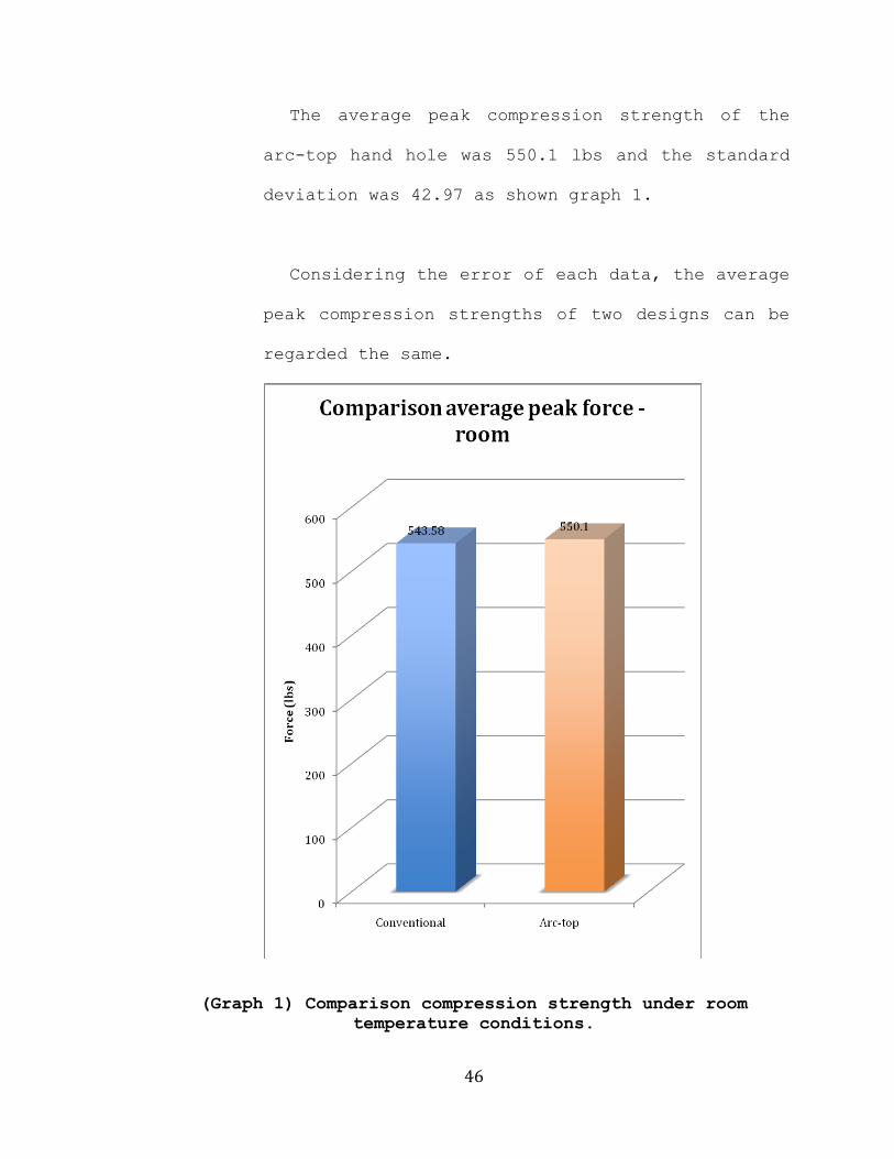
The average peak compression strength of the
arc-top hand hole was 550.1 lbs and the standard
deviation was 42.97 as shown graph 1.
Considering the error of each data, the average
peak compression strengths of two designs can be
regarded the same.
(Graph 1) Comparison compression strength under room
temperature conditions.
47
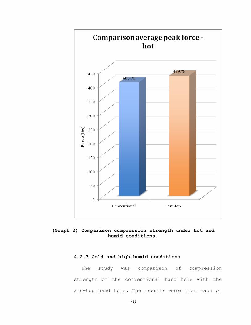
4.2.2 Hot and humid conditions
The study was comparison of compression
strength of the conventional hand hole with the
arc-top hand hole. The results were from each of
5 samples in hot (100F) and humid (80%) condition
for 72 hours before test.
The average peak compression strength of the
conventional hand hole was 405.98 lbs and the
standard deviation was 47.71.
The average peak compression strength of the
arc-top hand hole was 429.78 lbs and standard
deviation was 32.80 as shown graph 2.
Considering the error of each data, the average
peak compression strengths of two designs can be
regarded the same.
48
(Graph 2) Comparison compression strength under hot and
humid conditions.
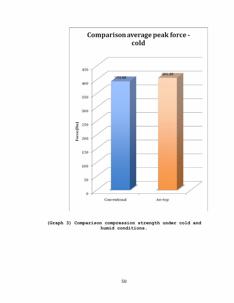
4.2.3 Cold and high humid conditions
The study was comparison of compression
strength of the conventional hand hole with the
arc-top hand hole. The results were from each of
49
5 samples in cold (40F)and humid (85%) condition
for 72 hours.
The average peak compression strength of the
conventional hand hole was 398.88 lbs and the
standard deviation was 11.54.
The average peak compression strength of the
arc-top hand hole was 406.48 lbs and the standard
deviation was 8.79 as shown graph 3.
Considering the error of each data, the average
peak compression strengths of two designs can be
regarded the same.
50
(Graph 3) Comparison compression strength under cold and
humid conditions.

51
5.0 Conclusion
The basic functions of Packaging are to contain,
transport, inform and protect. All functions are vitally
important for packaging so designers make an effort to
increase the performance of packaging functions. This
study specifically considers the compression strength of
the corrugated shipping containers that have hand holes.
Designers also make a new design of hand holes to make
the container easy to carry, and to increase tear
strength, as well as compression strength.
Two common styles of hand hole used in the study are
the conventional purpose hand hole (Figure B-5) and the
arc-top hand hole (Figure B-7), and which had almost same
width, 3.5 inches. ASTM D 6804-02 Standard Guide for Hand
Hole Design in Corrugated Boxes shows that the tear
strength of the arc-top hand hole offers over four times
as much strength conventional purpose hand hole.
However, the arc top hand hole has a larger opening
area, 5.41 sq inches, than the conventional hand hole‟s
opening area, 3.29 sq inches. A larger opening area
generally has an negative effect on the compression
strength of the container because the larger opening area
needs a larger space for distributing compression
strength. However, the dimension of the shipping

52
containers are limited; therefore, the size of the hand
hole needs to be considered according to the dimension of
the containers.
When the hand hole is located with enough space around
it for dispersion, the width of the hand hole is the only
variable directly related with the compression strength
of the corrugated shipping containers. The result of the
study showed that the compression strengths of two
different samples were the same in all different
conditions, even though the arc-top hand hole‟s opening
area is 1.64 times larger than the conventional hand
hole‟s opening area. This study did not calculate the
size of the appropriate space around the hand holes to
distribute the compression strength, so it used a common
design to give enough space for dispersion.
In conclusion, the compression strengths of corrugated
shipping containers and corrugated fiber boards are not
related with the size of the opening area. The
compression strength is only related to the width of the
opening area if the hole is located properly, and has
enough space for distributing the compression strength.
As a result, resistance forces of containers are the
same if the sums of the width of the hand holes are the
same and the hand holes have enough space to distribute

53
the compression stress, even though the designs of the
hand holes are different.

54
6.0 Recommendations
There are many designs of hand holes for the
corrugated shipping containers. This study used only two
common styles the hand holes. In addition, two hand holes
are located in the same position to allow for enough
space to distribute a load stress and this study only
compared two different designs of hand holes in three
different conditions. Therefore, a future study is
recommended to use more variety of designs of the hand
holes to compare compression strength and opening area
and to find the placement that will achieve optimum
results.
In addition, the corrugated board is moisture-
sensitive material. A future study is also recommended to
find the difference of each decrease ratio of the
compression strength of the corrugated shipping container
without hand holes under controlled condition and various
extreme conditions and the compression strength of the
corrugated shipping container with hand holes under
controlled condition and various extreme conditions, such
as high humid and low humid conditions. This will allow
for comparisons between corrugated shipping containers
with hand holes and those without.

55
7.0 Appendix A
(Table A- 1) BCT data of samples having the conventional
hand hole under room conditions.
Normal-conventional hand hole
Peak force Deflection
Sample #1 582.4 lbs 0.22 inches
Sample #2 538 lbs 0.22 inches
Sample #3 510.9 lbs 0.19 inches
Sample #4 531.4 lbs 0.2 inches
Sample #5 555.2 lbs 0.24 inches
(Graph A- 1) Compression strength of samples having the
conventional hand hole under room conditions.

56
(Table A- 2) BCT data of samples having the arc-top hand
hole under room conditions.
Normal-arc top hand hole
Peak force Deflection
Sample #1 496.9 0.22
Sample #2 609.5 0.29
Sample #3 522.7 0.18
Sample #4 529.9 0.18
Sample #5 591.5 0.3
(Graph A- 2) Compression strength of samples having the
arc-top hand hole under room conditions.

57
(Table A- 3) BCT data of samples having the conventional
hand hole under hot and humid conditions.
(Graph A- 3) Compression strength of samples having the
conventional hand hole under hot and humid conditions.
Hot-conventional hand hole
Peak force Deflection
Sample #1 445.5 0.24
Sample #2 312.6 0.13
Sample #3 433.2 0.21
Sample #4 417.8 0.18
Sample #5 420.8 0.21

58
(Table A- 4) BCT data of samples having the arc-top hand
hole under hot and humid conditions.
Hot-arc top hand hole
Peak force Deflection
Sample #1 436.7 0.23
Sample #2 428.5 0.24
Sample #3 468.9 0.22
Sample #4 444.8 0.22
Sample #5 370 0.19
(Graph A- 4) Compression strength of samples having the
arc-top hand hole under hot and humid conditions.

59
(Table A- 5) BCT data of samples having the conventional
hand hole under cold and humid conditions.
cold-conventional hand hole
peak force Deflection
sample #1 402 0.21
sample #2 407 0.21
sample #3 377.4 0.21
sample #4 383 0.2
sample #5 400 0.22
(Graph A- 5) Compression strength of samples having the
conventional hand hole under cold and humid conditions.

60
(Table A- 6) BCT data of samples having the arc-top hand
hole under cold and humid conditions.
cold-arc top hand hole
peak force Deflection
sample #1 406.5 0.22
sample #2 410.7 0.21
sample #3 409.7 0.23
sample #4 415.6 0.23
sample #5 389.9 0.21
(Graph A- 6) Compression strength of samples having the
arc-top hand hole under cold and humid conditions.

61
8.0 Appendix B
(Figure B- 1) Conditioning table <ISTA 2A 2008 – Page 6>.

62
(Figure B- 2) 72hours graph for cold and humid
conditioning.
(Figure B- 3) 72hours graph for hot and humid conditioning.
63
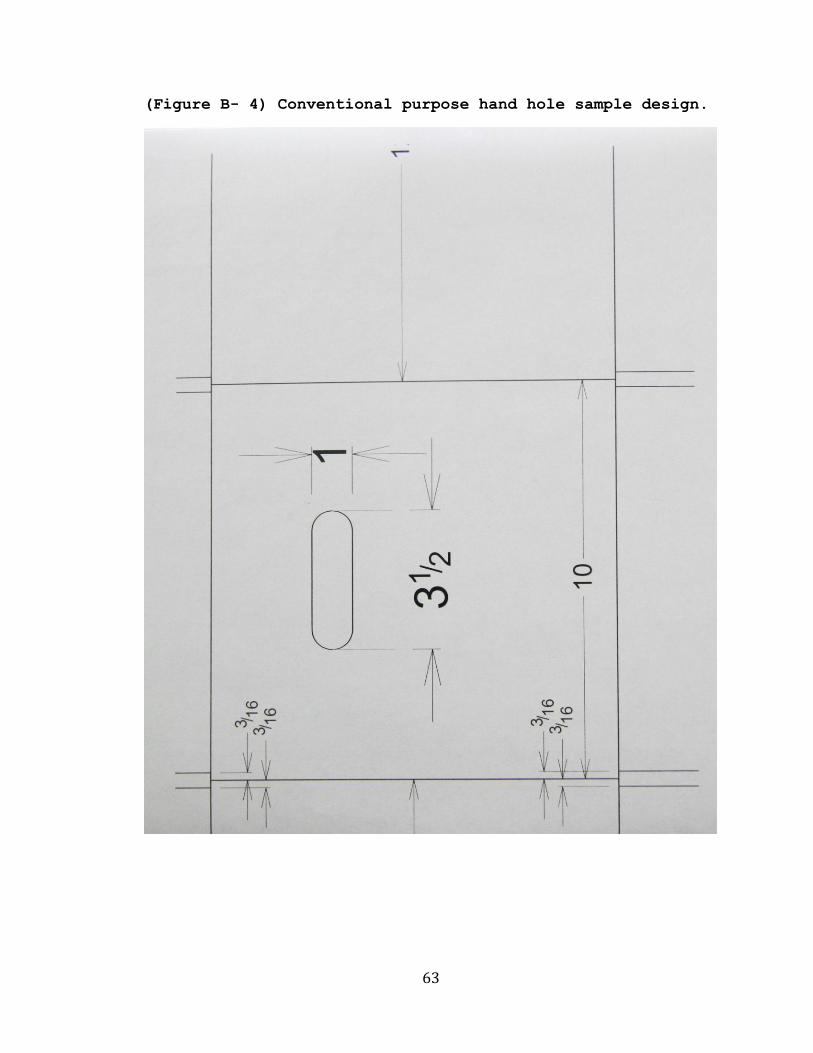
(Figure B- 4) Conventional purpose hand hole sample design.

64
(Figure B- 5) Box sample design having Conventional purpose
hand hole.

65
(Figure B- 6) Arc-top hand hole sample design.

66
(Figure B- 7) Box sample design having arc-top hand hole

67
(Figure B- 8) Constant rate control configuration.

68
9.0 Appendix C (Samples of BCT test result)
(Graph C- 1) BCT data of sample having conventional hand-
hole under room conditions <Sample Graph 1>

69
(Graph C- 2) BCT data of sample having arc top hand-hole
under room conditions <Sample Graph 2>

70
(Graph C- 3) BCT data of sample having arc top hand-
hole under hot and humid conditions <Sample Graph 3>

71
(Graph C- 4) BCT data of sample having conventional hand-
hole under hot and humid conditions <Sample Graph 4>

72
(Graph C- 5) BCT data of sample having conventional hand-
hole under cold and humid conditions <Sample Graph 5>

73
(Graph C- 6) BCT data of sample having arc top hand-hole
under cold and humid conditions <Sample Graph 6>

74
10.0 Works Cited
ASTM D 6804-02, “Standard Guide for Hand Hole Design in
Corrugated Boxes,” Philadelphia, ASTM, 2007.
ASTM D 5639, “Selection of Corrugated Fiberboard
materials and Box Construction Based on Performance
Requirements,” Philadelphia, ASTM, 2007.
ASTM D 642-00, “Standard Test Method for Determining
Compressive Resistance of Shipping Containers, Components,
and Unit Loads,” Philadelphia, ASTM, 2007.
Diana Twede and Susan E. M. Selke.“Cartons, crates and
corrugated board,” Lancaster, PA, DEStech Publications,
2005.
Eyre, R. Michael and Kaczor, A. Nancy. “The effect of
flexographic printing on the compression strength of
corrugated shipping containers,” Packaging Science
Department, Rochester Institute of Technology, 1990.

75
F.A. Paine. “The Packaging User‟s hand book,”
Bishopbriggs, Glasgow, Blackie Academic & Professional,
1991.
Fibre Box Association. “Fibre box handbook,” Rolling
Meadows, IL, Fibre Box Association., 1999.
Hakan Markstrom. “Testing methods ad instruments for
corrugated board,” Sweden, Lorentzen & Wettre, 1988.
Hewlett Packard Packaging department.“Four ways to define
the environment distribution,” 2004.
<http://www.hp.com/packaging/made/FinalReport/defining_a_
distribution_environm.htm>
Jonhkoo Han and Jong Min Park. “Finite element analysis
of vent/hand hole designs for corrugated fibreboard
boxes,” Packaging Technology and science, Vol.20, 2007.
39-47.
Jonson, Gunilla. “Corrugated BoardPackaging,”
Leatherhead, UK.,Pira International, 1995.

76
Mark J. Kirwan. “Paper and Paperboard Packaging
Technology,” London, UK: Blackwell, 2005.
Richard K. Brandenburg and Julian June-Ling
Lee.“Fundamentals of packaging dynamics,” Franklin Park,
IL, L.A.B. Equipment, 2001.
Richard John Curatalo. “A comparative study of the
compression strength of corrugated shipping container and
corrugated board, based on different corrugated
directions,” Packaging Science Department, Rochester
Institute of Technology, 2000.
Singh, J., Manley, J., Wallace, F., Olsen, E., and Singh,
S. P. “The Effect of Ventilation and Hand Holes on Loss
of Compression Strength in Corrugated Boxes,” Journal of
Applied Packaging Research, Vol. 2, No. 4, June 2008, P.
227-238.
Soroka, Walter. “Fundamentals of Packaging Technology,”
Institute of Packaging Professionals, 1995.
Sriratbunterng, Worawut. “The compression strength
comparison of corrugated shipping containers, printed by

77
thick and thin plate,” Packaging Science Department,
Rochester Institute of Technology, 1998.
Thomas J. Urbanik and Benjamin Frank. “Box compression
analysis of world-wide data spanning 46 years,” Wood and
fiber science, Vol. 38, July 2006, P.399-416.