Embed Size (px)
Citation preview

Corrugated Hose Loop Calculations
Mode: variable radius “loop” Point M motion is horizontal Data: F : fixed reference point M : movable point D = MM’ : M displacement E = 2R : minimum horizontal distance between F and M a : eventual level difference between F and M
Examples of use: refer to the first mode: Problem: live strength of a some hose Ø 1” + 1 braid, conveying fuel oil at 120oC and 20 bar pressure, for an installation where D = 500mm, E = 600mm, ā = 150mm (F located under MM’) Solution: the following gives minimum bending radius:
The loop installation is one of the most common application for metal hoses. It allows the flexible hose assembly to work properly. Care must always be exercised to ensure that point F and M always move in the same line so that the hose assemblies are not subjected to torque.
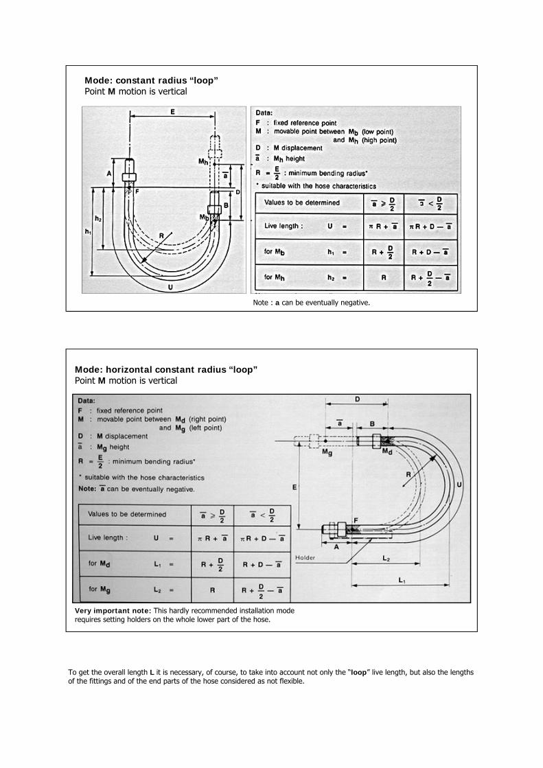
Mode: constant radius “loop” Point M motion is vertical
Note : a can be eventually negative.
Mode: horizontal constant radius “loop” Point M motion is vertical
Very important note: This hardly recommended installation mode requires setting holders on the whole lower part of the hose.
To get the overall length L it is necessary, of course, to take into account not only the “loop” live length, but also the lengths of the fittings and of the end parts of the hose considered as not flexible.
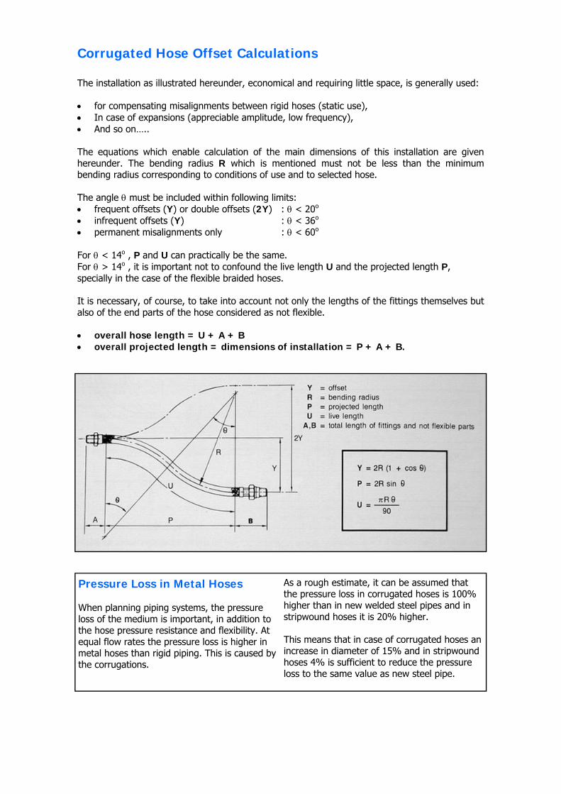
The installation as illustrated hereunder, economical and requiring little space, is generally used: • for compensating misalignments between rigid hoses (static use), • In case of expansions (appreciable amplitude, low frequency), • And so on….. The equations which enable calculation of the main dimensions of this installation are given hereunder. The bending radius R which is mentioned must not be less than the minimum bending radius corresponding to conditions of use and to selected hose. The angle θ must be included within following limits: • frequent offsets (Y) or double offsets (2Y) : θ < 20o • infrequent offsets (Y) : θ < 36o • permanent misalignments only : θ < 60o
For θ < 14o , P and U can practically be the same. For θ > 14o , it is important not to confound the live length U and the projected length P, specially in the case of the flexible braided hoses. It is necessary, of course, to take into account not only the lengths of the fittings themselves but also of the end parts of the hose considered as not flexible. • overall hose length = U + A + B • overall projected length = dimensions of installation = P + A + B.
Corrugated Hose Offset Calculations
Pressure Loss in Metal Hoses When planning piping systems, the pressure loss of the medium is important, in addition to the hose pressure resistance and flexibility. At equal flow rates the pressure loss is higher in metal hoses than rigid piping. This is caused by the corrugations.
As a rough estimate, it can be assumed that the pressure loss in corrugated hoses is 100% higher than in new welded steel pipes and in stripwound hoses it is 20% higher. This means that in case of corrugated hoses an increase in diameter of 15% and in stripwound hoses 4% is sufficient to reduce the pressure loss to the same value as new steel pipe.
Guide to Correct Installation • Allow flexibles to hang naturally from end fittings. • Avoid short radii and S-bends. • Keep fitting ends or flanges parallel. • Do not be tempted to use a shorter-than-recommended length. • Use pipe hangers so that no weight is carried by the flexibles. • Protect outer braid or tubing with non-flammable material if welding nearby. • NEVER put valves between flexibles and equipment. • Locate valves only at the piping end. • Install the unit to the exact normal length. • Avoid compressing or stretching. • Line up bolt holes of mating flanges accurately. • A floating flange on one end of a connector will simplify installation. • Always use two wrenches to prevent torque when a flexible connector with screwed ends is
being fitted. • Anchor the flexible securely at the piping end - NEVER at the equipment end. • Restrict motion to a single plane. Use pre-bent units to handle multiple movements.
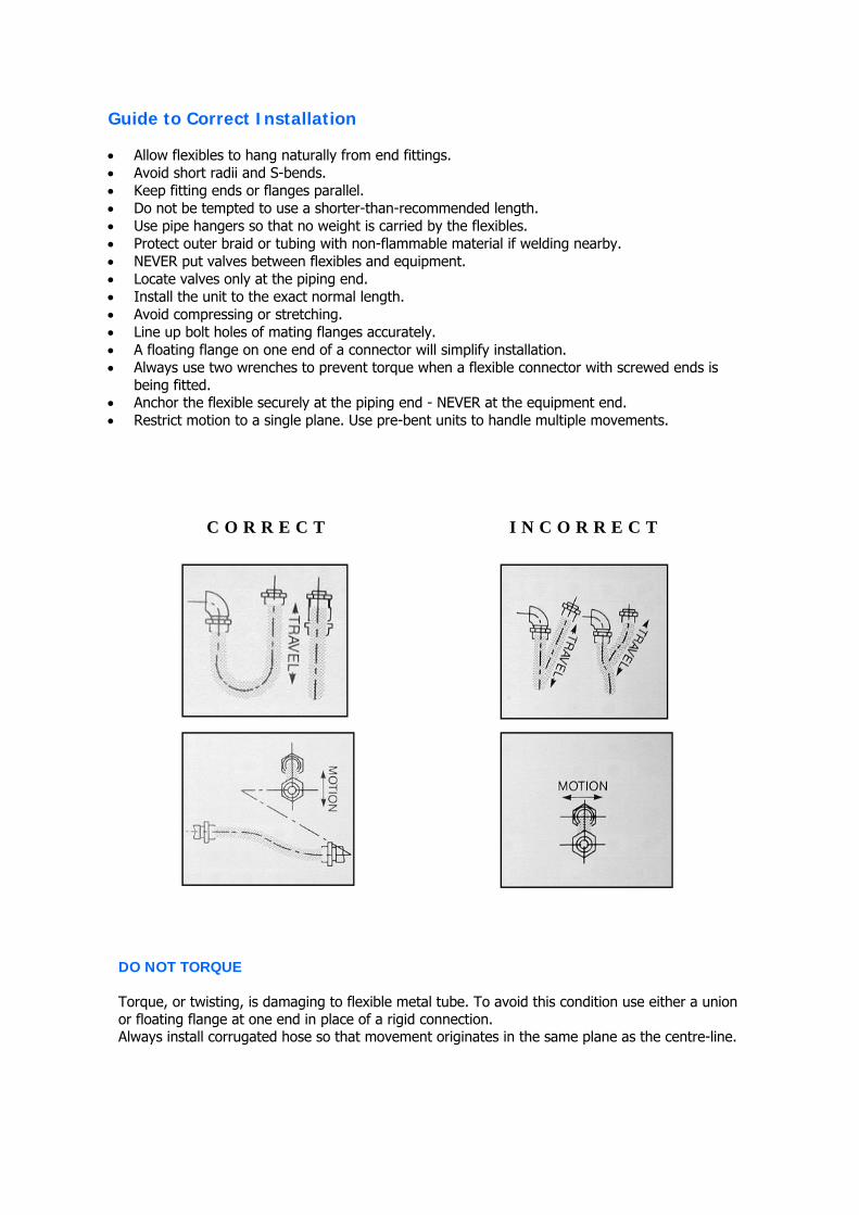
C O R R E C T I N C O R R E C T
DO NOT TORQUE Torque, or twisting, is damaging to flexible metal tube. To avoid this condition use either a union or floating flange at one end in place of a rigid connection. Always install corrugated hose so that movement originates in the same plane as the centre-line.
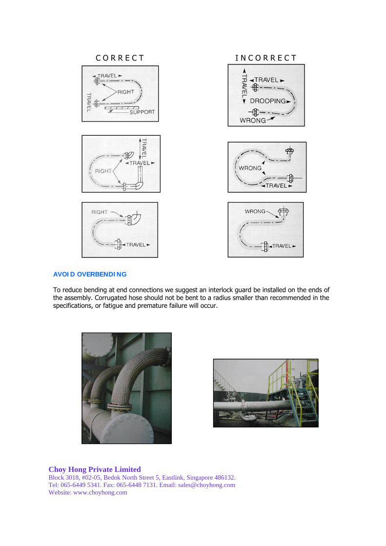
C O R R E C T I N C O R R E C T
AVOID OVERBENDING To reduce bending at end connections we suggest an interlock guard be installed on the ends of the assembly. Corrugated hose should not be bent to a radius smaller than recommended in the specifications, or fatigue and premature failure will occur.
Choy Hong Private Limited Block 3018, #02-05, Bedok North Street 5, Eastlink, Singapore 486132. Tel: 065-6449 5341. Fax: 065-6448 7131. Email: [email protected] Website: www.choyhong.com