Embed Size (px)
Citation preview

RE 95230-B/08.2015 Replaces: 03.06English
Analog Amplifier RA
Instruction manual
2/36 Bosch Rexroth AG Analog Amplifier RA RE 95230-B/08.2015
Manufacturer
Bosch Rexroth AG Mobile Applications Glockeraustraße 4 89275 Elchingen, Germany Service Tel. +49 9352 40 50 60 [email protected] www.boschrexroth.com/mobile-electronics
www.boschrexroth.com/addresses
At this Internet address you will also find information about the contacts in the different countries.
About this instruction manual
This instruction manual describes the analog amplifier RA from Rexroth. You will need the individual chapters of the manual in the various phases of working with the analog amplifier:
• In "Safety instructions" you will find information about avoiding dangers and injury when using the analog amplifier in machines and systems.
• In "Functional description" you will find background information about understanding the way the analog amplifier works, and about its usage, benefits, major features and technical data.
• In "Project planning notes" you will learn about the requirements for using the analog amplifier.
• In "Installation" you will find, amongst other things, notes on the installation position, mounting and mating connector assembly.
• In "Block circuit diagram" you will find a block circuit diagram of the analog amplifier.
• In "Pin assignment" you will find an overview table with a brief description of all the pins.
• In "Connection variants (standard)" and "Examples of connection variants" you will learn how to use the analog amplifier in different ways.
• In "Commissioning" you will learn how to define parameters for the analog amplifier, and how you can rectify typical commissioning problems.
Content
1 Safety Instructions ................................................................3
2 Functional Description ........................................................42.1 Usage and benefits ...........................................................42.2 Features................................................................................42.3 Operating modes ...............................................................52.4 Assignment and function of the LEDs and
adjusting potentiometer ....................................................62.5 Technical data .....................................................................7
3 Project Planning Notes ........................................................8
4 Installation .................................................................................94.1 Notes on unpacking ..........................................................94.2 Preparing the analog amplifier for installation .............94.3 Installation position ............................................................94.4 Mounting ............................................................................104.5 Connector assembly .......................................................10
5 Block Circuit Diagram ........................................................19
6 Pin Assignment .................................................................... 20
7 Connection Variants (Standard) .................................. 227.1 Parallel operation ............................................................ 227.2 Toggling operation with one potentiometer ............. 24
8 Examples of Connection Variants .............................. 268.1 Variants when wiring an input or in parallel operation 268.2 Variants with independent wiring ................................ 288.3 Variants with parallel operation of the output stages 29
9 Commissioning .....................................................................319.1 Defining parameters ........................................................319.2 Rectification of typical problems ................................. 329.3 Factory settings ............................................................... 329.4 Repairs and replacement .............................................. 329.5 Maintenance and cleaning ............................................ 33
Index ...................................................................................................... 35
Bosch Rexroth AGRE 95230-B/08.2015 Analog Amplifier RA 3/36
1 Safety Instructions
In order to avoid injury and hazards, please note the following general safety instructions:
• Setup, installation and operation of the equipment cannot be monitored. The user is therefore himself responsible for the correct use of the product. The valid manufacturer’s data for the machine/the vehicle must be noted without fail during installation.
• The user must check the analog amplifier for any visible faults before starting use, and observe faults during operation. A device, on which safety-relevant faults have been found, must not be commissioned or used further. Safety-relevant faults must be rectified before further operation.
• Analog amplifiers, in contrast to digital controller, only permit limited diagnosis and monitoring facilities. The use of the analog amplifier in applications where dangerous machine conditions could arise if a fault occurs is not permitted without additional external protective measures.
• The details stated in the technical data sheet RE 95 230 must be met and must not be exceeded, in order to ensure operation according to specifications.
• The safety details for the machine/vehicle must be met.
• If the analog amplifier fails, malfunctions – such as undesirable actuation or switching off of one or more solenoids – cannot be prevented safely.
• In emergency situations or where major functions fail, the operating voltage must be switched off externally. For this the power supply to the electronics will be interrupted by an emergency stop switch. The emergency stop switch must be installed in an easily accessible position for the operator. Safe braking must be ensured when the emergency stop function is activated.
• Electrical connection and commissioning may only be carried out by a qualifed member of staff.
• The analog amplifier may only be wired when it has been de-energized.
• Damaged devices must not be commissioned. It is not permitted to connect to public supply networks.
• Mixing up the ground connections on the analog amplifier can lead to functional impairments.
• The cable connection must be strain relieved and fixed in such a way that no friction or corrosion can occur on the connector contacts due to vibration. The contacts are to be protected against corrosion.
• If the solenoid output is overloaded (short circuit) the affected output is not switched off permanently.
• In the case of cable breakage on one of the external potentiometers, the outputs can continue to pass current and are not switched off on all connection variants. In this case, however, the fault output (Pin 15) is activated, depending on the type of connection.
• In order to avoid faults, connect the wiring shield from/to the potentiometers on one side only to the equipment or to vehicle ground via a low-resistance connection.
• Cables to the electronics must not be routed close to other power-conducting cables in the machine or vehicle.
• Sufficient distance from radio systems must be maintained.
• Do not use any radio devices or mobile phones in the driver’s compartment or close to the control electronics without a suitable external antenna!
• During electrical welding operations and electrical painting work, all connectors must be unplugged from the electronics.
• A permanent wetting of the analog amplifier with hydraulic fluids, acids or leaching solutions is to be avoided.
• The suggested circuits do not imply any technical liability for the system on the part of Rexroth.
• The two PWM outputs must not be connected to each other (bridged)!
4/36 Bosch Rexroth AG Analog Amplifier RA RE 95230-B/08.2015
2 Functional Description
2.1 Usage and benefits
The analog amplifier is designed to control up to two proportional solenoids. The specified control voltage is processed in the amplifier as the input variable. As the output variable, the analog amplifier provides a controlled electrical current to control the proportional solenoids.
The analog amplifier RA can be used to actuate up to two proportional solenoids in one device (e.g. a toggling axial piston unit or a valve disk with separate actuation of the proportional solenoids) or to control two devices separately from each other (e.g. two simple axial piston units or valves). The use of only one proportional output is possible. A 1 A output for a switching function is also available.
2.2 Features
The electronic analog amplifier offers the following features:
• optional reciprocal locking of the proportional solenoid control
• voltage supply for external setpoint potentiometer
• conditional monitoring of the setpoint potentiometer for cable breakage and short circuit
• externally controllable switching output
• error output
• separately adjustable times for up and down ramps for each solenoid
• overloading protection, overvoltage protection, conditional short circuit protection
• separately adjustable currents Imin (offset) and Imax (gradient) for each solenoid
• externally adjustable PWM frequency
Bosch Rexroth AGRE 95230-B/08.2015 Analog Amplifier RA 5/36
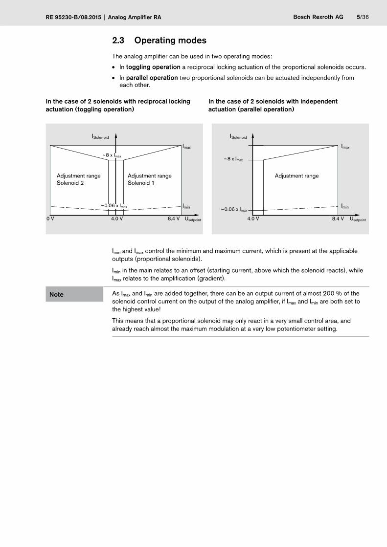
2.3 Operating modes
The analog amplifier can be used in two operating modes:
• In toggling operation a reciprocal locking actuation of the proportional solenoids occurs.
• In parallel operation two proportional solenoids can be actuated independently from each other.
In the case of 2 solenoids with reciprocal locking actuation (toggling operation)
In the case of 2 solenoids with independent actuation (parallel operation)
Adjustment range Solenoid 2
Adjustment range Solenoid 1
~0.06 x Imax
0 V 4.0 V 8.4 V Usetpoint
Imin
~8 x Imax
Imax
ISolenoid
Adjustment range
ISolenoid
Imin
Imax
~0.06 x Imax
~8 x Imax
4.0 V Usetpoint8.4 V
Imin and Imax control the minimum and maximum current, which is present at the applicable outputs (proportional solenoids).
Imin in the main relates to an offset (starting current, above which the solenoid reacts), while Imax relates to the amplification (gradient).
Note As Imax and Imin are added together, there can be an output current of almost 200 % of the solenoid control current on the output of the analog amplifier, if Imax and Imin are both set to the highest value!
This means that a proportional solenoid may only react in a very small control area, and already reach almost the maximum modulation at a very low potentiometer setting.

6/36 Bosch Rexroth AG Analog Amplifier RA RE 95230-B/08.2015
2.4 Assignment and function of the LEDs and adjusting potentiometer
Channel 1
Channel 2
LEDs
LEDs I2: yellow Power: green Error: red I1: yellow
The brightness of the LEDs I1 and I2 depends on the strength of the output current and therefore serves as a rough optical control.
The ramps control the time, which the output current needs to reach a new value. The control area lies between 100 ms and 10 s at a maximum change of Imin to Imax.
For the potentiometer, the following applies in general: A rotation to the right means an increase in the set value (longer ramp time and/or higher current).
Bosch Rexroth AGRE 95230-B/08.2015 Analog Amplifier RA 7/36
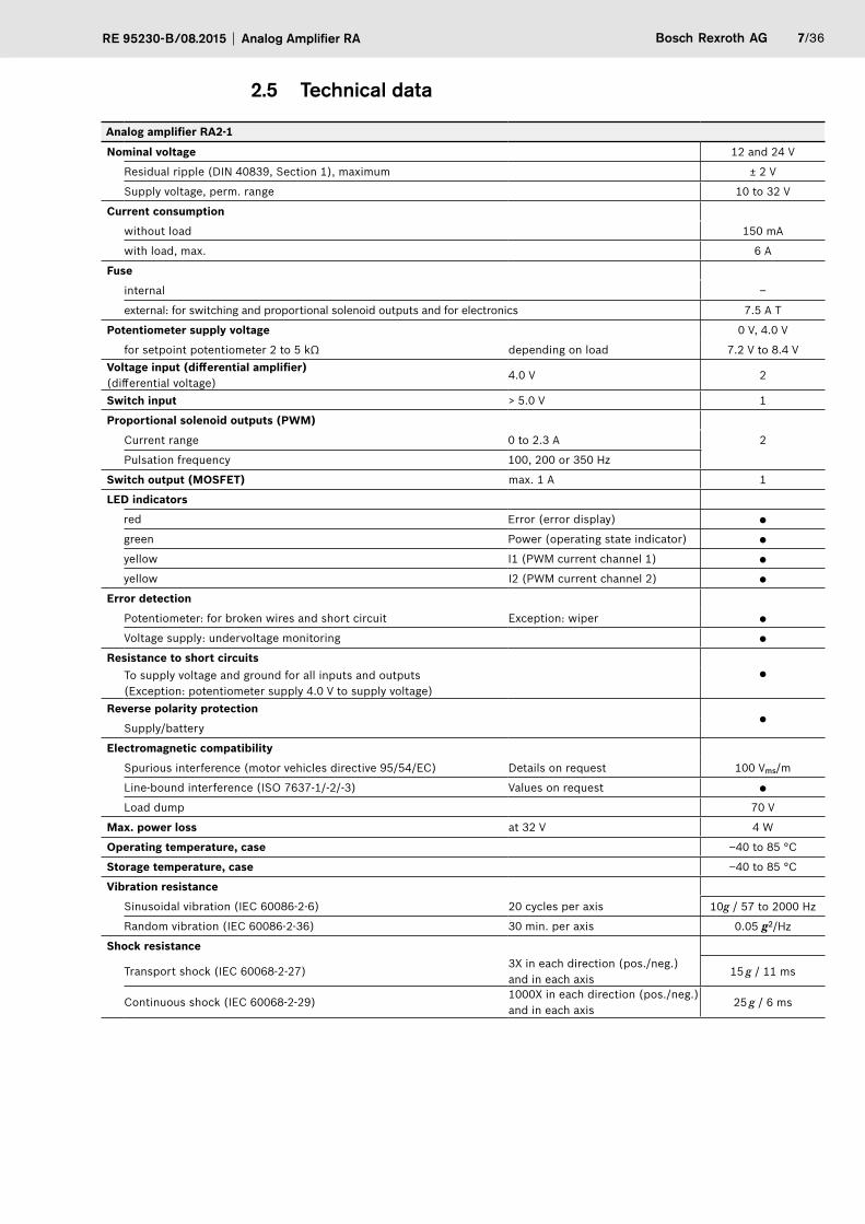
2.5 Technical data
Analog amplifier RA2-1
Nominal voltage 12 and 24 V
Residual ripple (DIN 40839, Section 1), maximum ± 2 V
Supply voltage, perm. range 10 to 32 V
Current consumption
without load 150 mA
with load, max. 6 A
Fuse
internal –
external: for switching and proportional solenoid outputs and for electronics 7.5 A T
Potentiometer supply voltage 0 V, 4.0 V
for setpoint potentiometer 2 to 5 kΩ depending on load 7.2 V to 8.4 VVoltage input (differential amplifier) (differential voltage)
4.0 V 2
Switch input > 5.0 V 1
Proportional solenoid outputs (PWM)
Current range 0 to 2.3 A 2
Pulsation frequency 100, 200 or 350 Hz
Switch output (MOSFET) max. 1 A 1
LED indicators
red Error (error display)
green Power (operating state indicator)
yellow I1 (PWM current channel 1)
yellow I2 (PWM current channel 2)
Error detection
Potentiometer: for broken wires and short circuit Exception: wiper
Voltage supply: undervoltage monitoring
Resistance to short circuitsTo supply voltage and ground for all inputs and outputs
(Exception: potentiometer supply 4.0 V to supply voltage)Reverse polarity protection
Supply/battery
Electromagnetic compatibility
Spurious interference (motor vehicles directive 95/54/EC) Details on request 100 Vms/m
Line-bound interference (ISO 7637-1/-2/-3) Values on request
Load dump 70 V
Max. power loss at 32 V 4 W
Operating temperature, case –40 to 85 °C
Storage temperature, case –40 to 85 °C
Vibration resistance
Sinusoidal vibration (IEC 60086-2-6) 20 cycles per axis 10g / 57 to 2000 Hz
Random vibration (IEC 60086-2-36) 30 min. per axis 0.05 g2/Hz
Shock resistance
Transport shock (IEC 60068-2-27)3X in each direction (pos./neg.) and in each axis
15 g / 11 ms
Continuous shock (IEC 60068-2-29)1000X in each direction (pos./neg.) and in each axis
25 g / 6 ms

8/36 Bosch Rexroth AG Analog Amplifier RA RE 95230-B/08.2015
Analog amplifier RA2-1
Resistance to moisture90 % (+25 °C to +55 °C)
IEC 60068-2-30Db; version 2
Resistance to salt spray72 h, 35°C, 5% NaCl
IEC 60068-2-11
Type of protection (DIN / EN 60529) with installed mating connector1) IP65
Case materialPlastic injection molding PA66 GF 35
Mass, approx. 0.3 kg
Outer dimensions Length 108 mm
Width 135 mm
Height 42 mm
1) for the appropriate routing of the connection cable, see “Installation position”
3 Project Planning Notes
When project planning a machine or a system with analog amplifier RA, you should take note of the following conditions:
• The total of the setpoints of parallel wired potentiometers (for parallel operation, see Page 9) must be in the range between 2 kWand 5 kW. Potentiometers with 4.7 kW or 5 kW are recommended.
• Do not use any freewheeling diodes in the proportional solenoid wires.
• Other inductive solenoids in the system should be equipped with freewheeling diodes.
• External switching contacts in the solenoid wires are not permitted.
• The interference immunity to electrostatic and electromagnetic fields depends to a great extent on the way the device is connected. When connecting the device, all the necessary electrical connections for the setting of the operating mode, e.g. the setting of the PWM frequency, must occur directly in/on the connector.
• The analog amplifier must not be used in potentially explosive environments.
• The analog amplifier is designed for DC voltage of 12 or 24 Volt.
• Any type of DC voltage signals can be used as setpoint sensor, e.g., potentiometers or external signals (in the specified range).
Bosch Rexroth AGRE 95230-B/08.2015 Analog Amplifier RA 9/36
4 Installation
The installation of the analog amplifier must be carried out by a qualified member of staff, a specialist trained or instructed person.
4.1 Notes on unpacking
When unpacking the analog amplifier please note the following information:
CAUTION Risk of damage
The device can fall out and be damaged as a result of an incorrect opening of the packaging.
• Only open the packaging from above.
Note The packaging consists of fully recyclable materials.
When disposing of the packaging, national legislation must be observed.
4.2 Preparing the analog amplifier for installation
In order to prepare the analog amplifier for installation:
1 Take the device out of the packaging.
2 Check the device for visible damage (e.g. cracks).
3 Compare the part number and designation with the details in the order confirmation. If the material number does not conform to that in the order confirmation, contact Rexroth Service for clarification.
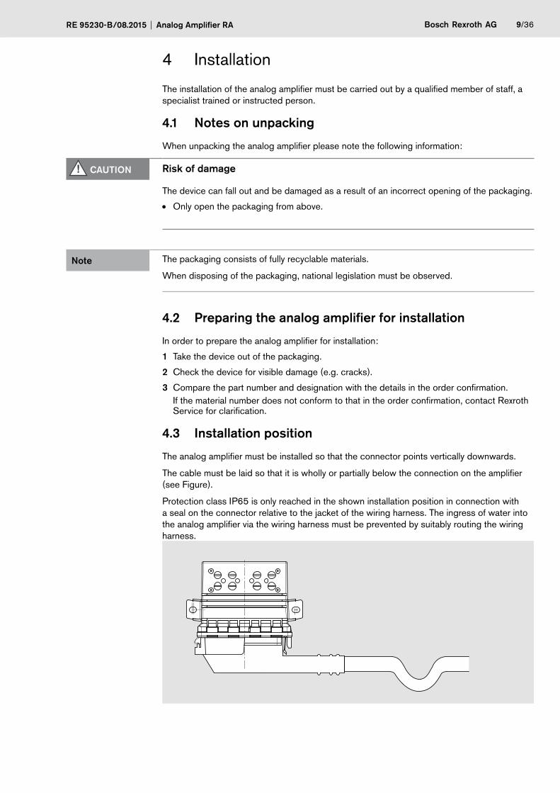
4.3 Installation position
The analog amplifier must be installed so that the connector points vertically downwards.
The cable must be laid so that it is wholly or partially below the connection on the amplifier (see Figure).
Protection class IP65 is only reached in the shown installation position in connection with a seal on the connector relative to the jacket of the wiring harness. The ingress of water into the analog amplifier via the wiring harness must be prevented by suitably routing the wiring harness.
10/36 Bosch Rexroth AG Analog Amplifier RA RE 95230-B/08.2015
4.4 Mounting
The analog amplifier RA has mounting brackets for installation.
Use M6 screws (not flat-head). Washers are essential. Tighten the screws with a torque of 4 Nm.
4.5 Connector assembly
The following explains how the mating connector for the Rexroth analog amplifier RA is crimped and installed.
The mating connector is not supplied with the analog amplifier RA. The complete set can be obtained from Rexroth under material number R902603063.
CAUTION Risk of damage
The Rexroth analog amplifier can be destroyed due to incorrect polarity on the outputs.
• Always ensure that the outputs have the correct polarity.
Valid documents
• Tyco Electronics AMP (114-18022): General guidelines for the processing of contacts with open crimping sleeves. This specification contains the general guidelines for the processing of AMP contacts with open wire and insulation crimping sleeves.
• Tyco Electronics AMP (114-18050): Junior Power Timer contact.This specification contains the guidelines for the processing of Junior Power Timer contacts and Junior Power Timer contacts "Type A".
Recommended tool
For crimping:
• Hand-held crimping device (Tyco AMP part number: 539635-1)
• Use (matrix) (Tyco AMP part number: 539674-2) for Junior Power Timer contact 927775-3 or 927783-3
For disassembly:
• Pin removal tool (Tyco AMP part number: 968107-1) for Junior Power Timer contact 927775-3 or 927783-3
Bosch Rexroth AGRE 95230-B/08.2015 Analog Amplifier RA 11/36
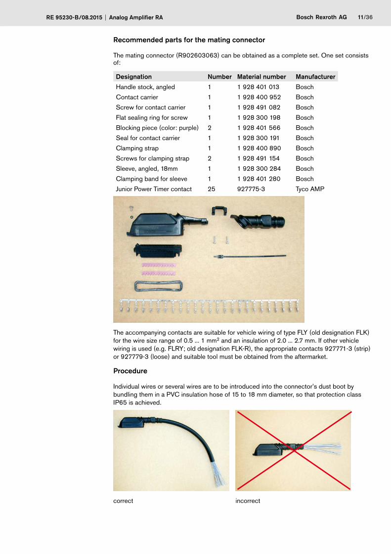
Recommended parts for the mating connector
The mating connector (R902603063) can be obtained as a complete set. One set consists of:
Designation Number Material number Manufacturer
Handle stock, angled 1 1 928 401 013 Bosch
Contact carrier 1 1 928 400 952 Bosch
Screw for contact carrier 1 1 928 491 082 Bosch
Flat sealing ring for screw 1 1 928 300 198 Bosch
Blocking piece (color: purple) 2 1 928 401 566 Bosch
Seal for contact carrier 1 1 928 300 191 Bosch
Clamping strap 1 1 928 400 890 Bosch
Screws for clamping strap 2 1 928 491 154 Bosch
Sleeve, angled, 18mm 1 1 928 300 284 Bosch
Clamping band for sleeve 1 1 928 401 280 Bosch
Junior Power Timer contact 25 927775-3 Tyco AMP
The accompanying contacts are suitable for vehicle wiring of type FLY (old designation FLK) for the wire size range of 0.5 ... 1 mm2 and an insulation of 2.0 ... 2.7 mm. If other vehicle wiring is used (e.g. FLRY; old designation FLK-R), the appropriate contacts 927771-3 (strip) or 927779-3 (loose) and suitable tool must be obtained from the aftermarket.
Procedure
Individual wires or several wires are to be introduced into the connector’s dust boot by bundling them in a PVC insulation hose of 15 to 18 mm diameter, so that protection class IP65 is achieved.
correct incorrect
12/36 Bosch Rexroth AG Analog Amplifier RA RE 95230-B/08.2015
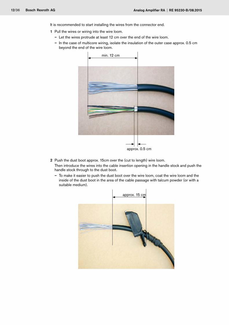
It is recommended to start installing the wires from the connector end.
1 Pull the wires or wiring into the wire loom.– Let the wires protrude at least 12 cm over the end of the wire loom.– In the case of multicore wiring, isolate the insulation of the outer case approx. 0.5 cm
beyond the end of the wire loom.
min. 12 cm
approx. 0.5 cm
2 Push the dust boot approx. 15cm over the (cut to length) wire loom.Then introduce the wires into the cable insertion opening in the handle stock and push the handle stock through to the dust boot.– To make it easier to push the dust boot over the wire loom, coat the wire loom and the
inside of the dust boot in the area of the cable passage with talcum powder (or with a suitable medium).
approx. 15 cm
Bosch Rexroth AGRE 95230-B/08.2015 Analog Amplifier RA 13/36
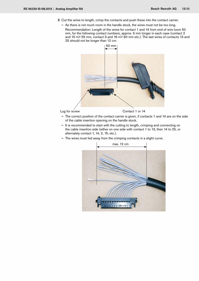
3 Cut the wires to length, crimp the contacts and push these into the contact carrier.– As there is not much room in the handle stock, the wires must not be too long.
Recommendation: Length of the wires for contact 1 and 14 from end of wire loom 50 mm, for the following contact numbers, approx. 5 mm longer in each case (contact 2 and 15 => 55 mm, contact 3 and 16 => 60 mm etc.). The last wires of contacts 13 and 25 should not be longer than 12 cm.
50 mm
Lug for screw Contact 1 or 14
– The correct position of the contact carrier is given, if contacts 1 and 14 are on the side of the cable insertion opening on the handle stock.
– It is recommended to start with the cutting to length, crimping and connecting on the cable insertion side (either on one side with contact 1 to 13, then 14 to 25, or alternately contact 1, 14, 2, 15, etc.).
– The wires must fed away from the crimping contacts in a slight curve.
max. 12 cm
14/36 Bosch Rexroth AG Analog Amplifier RA RE 95230-B/08.2015
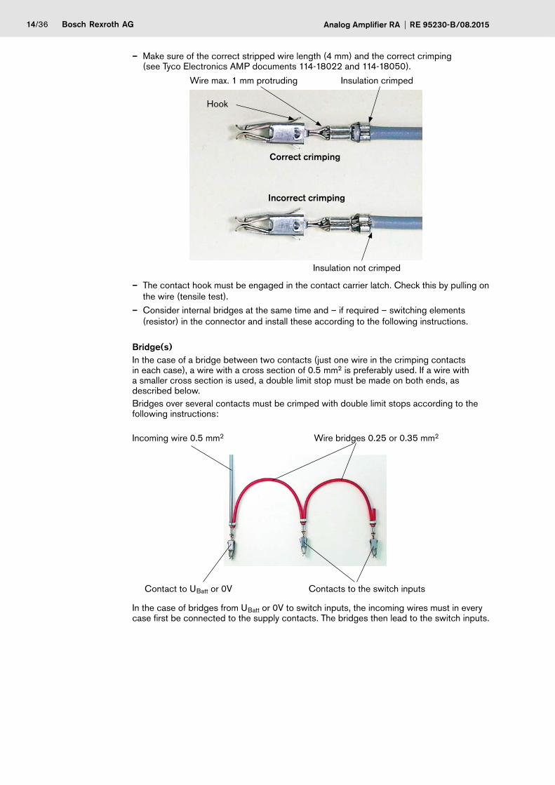
– Make sure of the correct stripped wire length (4 mm) and the correct crimping (see Tyco Electronics AMP documents 114-18022 and 114-18050).
Wire max. 1 mm protruding Insulation crimped
Insulation not crimped
Correct crimping
Incorrect crimping
Hook
– The contact hook must be engaged in the contact carrier latch. Check this by pulling on the wire (tensile test).
– Consider internal bridges at the same time and – if required – switching elements (resistor) in the connector and install these according to the following instructions.
Bridge(s)In the case of a bridge between two contacts (just one wire in the crimping contacts in each case), a wire with a cross section of 0.5 mm2 is preferably used. If a wire with a smaller cross section is used, a double limit stop must be made on both ends, as described below.Bridges over several contacts must be crimped with double limit stops according to the following instructions:
Incoming wire 0.5 mm2 Wire bridges 0.25 or 0.35 mm2
Contact to UBatt or 0V Contacts to the switch inputs
In the case of bridges from UBatt or 0V to switch inputs, the incoming wires must in every case first be connected to the supply contacts. The bridges then lead to the switch inputs.
Bosch Rexroth AGRE 95230-B/08.2015 Analog Amplifier RA 15/36
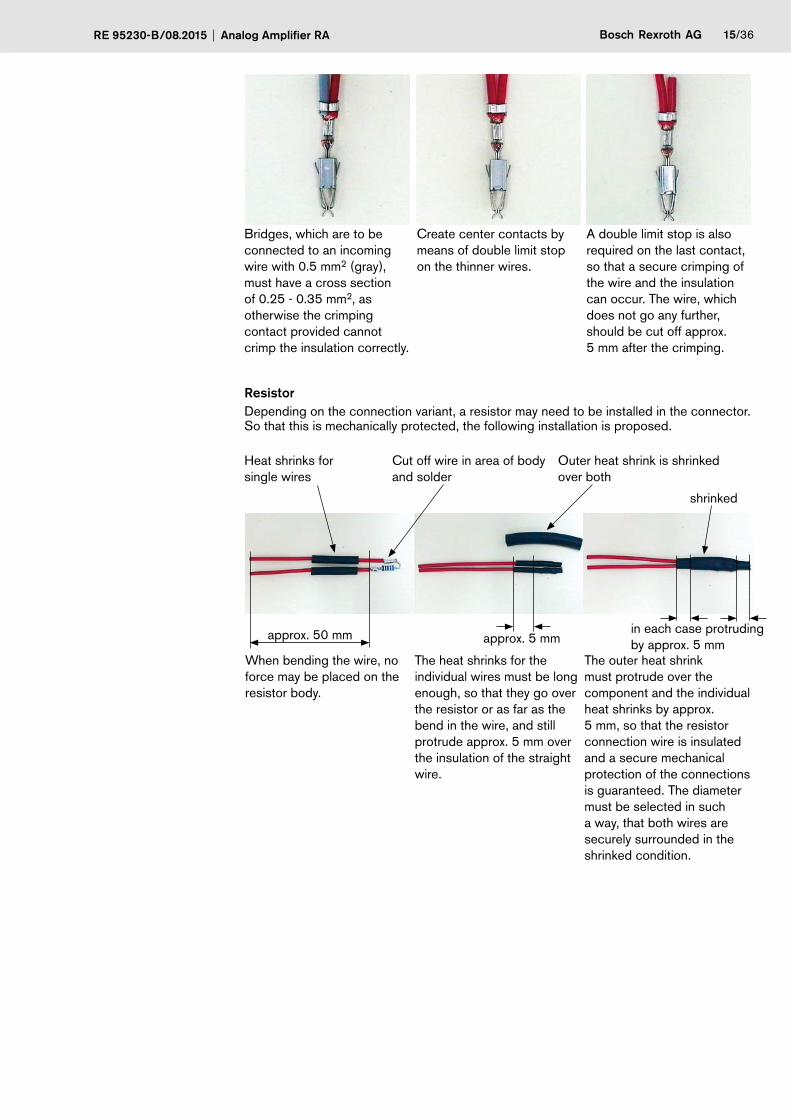
Bridges, which are to be connected to an incoming wire with 0.5 mm2 (gray), must have a cross section of 0.25 - 0.35 mm2, as otherwise the crimping contact provided cannot crimp the insulation correctly.
Create center contacts by means of double limit stop on the thinner wires.
A double limit stop is also required on the last contact, so that a secure crimping of the wire and the insulation can occur. The wire, which does not go any further, should be cut off approx. 5 mm after the crimping.
ResistorDepending on the connection variant, a resistor may need to be installed in the connector. So that this is mechanically protected, the following installation is proposed.
When bending the wire, no force may be placed on the resistor body.
Heat shrinks for single wires
Cut off wire in area of body and solder
Outer heat shrink is shrinked over both
shrinked
approx. 50 mm approx. 5 mm
The heat shrinks for the individual wires must be long enough, so that they go over the resistor or as far as the bend in the wire, and still protrude approx. 5 mm over the insulation of the straight wire.
The outer heat shrink must protrude over the component and the individual heat shrinks by approx. 5 mm, so that the resistor connection wire is insulated and a secure mechanical protection of the connections is guaranteed. The diameter must be selected in such a way, that both wires are securely surrounded in the shrinked condition.
in each case protruding by approx. 5 mm
16/36 Bosch Rexroth AG Analog Amplifier RA RE 95230-B/08.2015
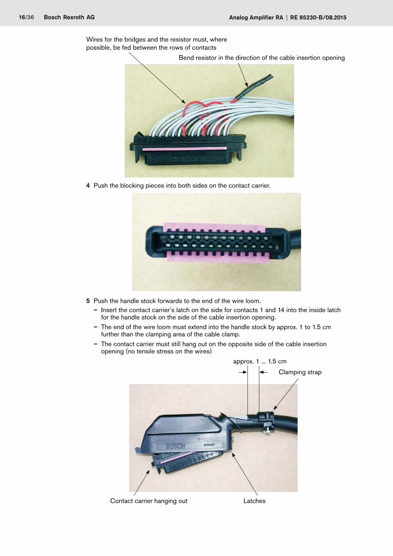
Wires for the bridges and the resistor must, where possible, be fed between the rows of contacts
Bend resistor in the direction of the cable insertion opening
4 Push the blocking pieces into both sides on the contact carrier.
5 Push the handle stock forwards to the end of the wire loom.– Insert the contact carrier’s latch on the side for contacts 1 and 14 into the inside latch
for the handle stock on the side of the cable insertion opening.– The end of the wire loom must extend into the handle stock by approx. 1 to 1.5 cm
further than the clamping area of the cable clamp.– The contact carrier must still hang out on the opposite side of the cable insertion
opening (no tensile stress on the wires)
approx. 1 ... 1.5 cm
Contact carrier hanging out
Clamping strap
Latches

Bosch Rexroth AGRE 95230-B/08.2015 Analog Amplifier RA 17/36
6 Screw the clamp strap with the appropriate screws.– Tightening torque 0.9 – 1.1 Nm– If the clamping of the wire loom (e.g. if there are only a few wires) is too low, splicing
tape must be applied in the clamping area.
7 Insert the contact carrier fully into the handle stock.– No great amount of force should be necessary, otherwise wires or contacts may be
damaged; it may be necessary to check the correct wire length or the wire guide (only a slight curve over the contacts; no twisting of the wires with each other).
– Make sure that the (optional) resistor is seated correctly.
Position of resistor
8 Equip the screw for the contact carrier with a flat sealing ring.
9 Screw the contact carrier and handle stock with the screw (and flat sealing ring!).– Tightening torque 0.4 – 0.7 Nm
10 Insert the seal for the contact carrier.– The seal must be inserted with the concave side to the contact carrier (inward)
(straight surface must be visible from the outside).– The seal must lie fully inserted between the handle stock and the contact carrier.
Place concave side inwards to the contact carrier
Straight surface visible from outside
18/36 Bosch Rexroth AG Analog Amplifier RA RE 95230-B/08.2015
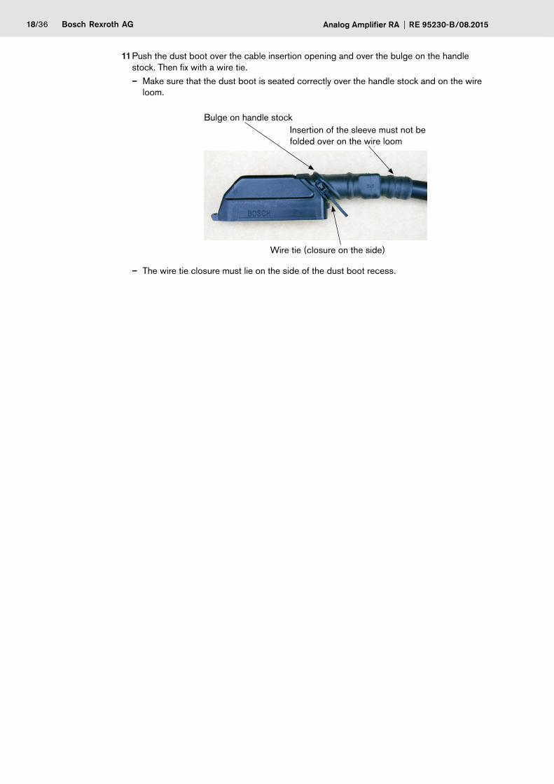
11 Push the dust boot over the cable insertion opening and over the bulge on the handle stock. Then fix with a wire tie.– Make sure that the dust boot is seated correctly over the handle stock and on the wire
loom.
Bulge on handle stockInsertion of the sleeve must not be folded over on the wire loom
Wire tie (closure on the side)
– The wire tie closure must lie on the side of the dust boot recess.
Bosch Rexroth AGRE 95230-B/08.2015 Analog Amplifier RA 19/36
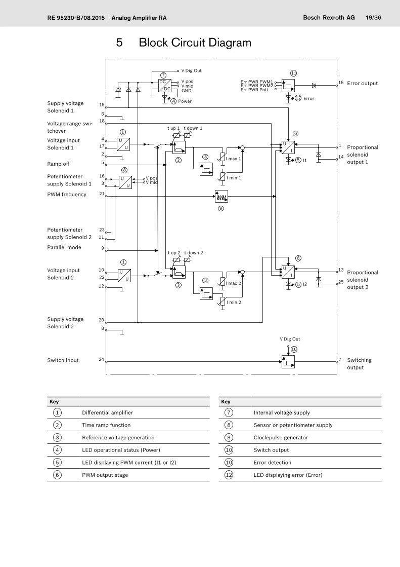
5 Block Circuit Diagram
1
V Dig Out
DC
V posV mid
t up 1 t down 1
GND
DC
5
IU
I min 1
I max 1 I1
I2
ErrorPower
6
12
11
Err PWR PWM1 Err PWR PWM2Err PWR Poti
6
5
U I
I min 2
I max 2
8
2
19
1
15
14
13
25
7
618
417
2
5
163
21
2311
9
1022
12
20
24
8
3
UU
U U
V posV mid
4
7
9
1
23 U
t up 2 t down 2
U
10
V Dig Out
Error output
Proportional solenoid output 1
Proportional solenoid output 2
Switching output
Supply voltage Solenoid 1
Supply voltage Solenoid 2
Voltage range swi-tchover
Voltage input Solenoid 1
Voltage input Solenoid 2
Ramp off
Potentiometer supply Solenoid 1
Potentiometer supply Solenoid 2
PWM frequency
Parallel mode
Switch input
Key
1 Differential amplifier
2 Time ramp function
3 Reference voltage generation
4 LED operational status (Power)
5 LED displaying PWM current (I1 or I2)
6 PWM output stage
Key
7 Internal voltage supply
8 Sensor or potentiometer supply
9 Clock-pulse generator
10 Switch output
10 Error detection
12 LED displaying error (Error)
20/36 Bosch Rexroth AG Analog Amplifier RA RE 95230-B/08.2015
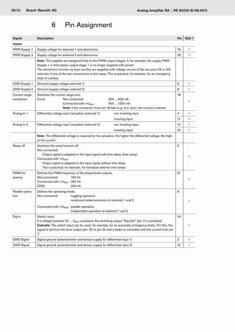
6 Pin Assignment
Signal Description Pin RA2-1
Inputs
PWR Supply 1 Supply voltage for solenoid 1 and electronics 19 P
PWR Supply 2 Supply voltage for solenoid 2 and electronics 20 P
Note: The supplies are assigned firmly to the PWM output stages. If, for example, the supply PWR Supply 1 is interrupted, output stage 1 is no longer supplied with power. The electronics function as soon as they are supplied with voltage via one of the two pins (19 or 20), and even if one of the two connections is torn away. This is practical, for example, for an emergency stop on a press.
GND Supply 1 Ground (supply voltage solenoid 1) 6 P
GND Supply 2 Ground (supply voltage solenoid 2) 8 P
Current range switchover
Switches the current range over. Errors Not connected: 200 ... 600 mA
Connected with +UBatt: 400 ... 1200 mA Note: If the connection from pin 18 fails (e.g. torn wire), the current is halved.
18
P
Analog In 1 Differential voltage input (actuation solenoid 1): non inverting input 4 P
inverting input 17 P
Analog In 2 Differential voltage input (actuation solenoid 2): non inverting input 10 P
inverting input 22 P
Note: The differential voltage is required for the actuation; the higher the differential voltage, the high-er the current.
Ramp off Switches the ramp function off.Not connected: Output signal is adapted to the input signal with time delay (time ramp).Connected with +UBatt: Output signal is adapted to the input signal without time delay. This is practical, for example, for individual external time ramps.
5
P
PWM fre-quency
Defines the PWM frequency of the proportional outputs. Not connected: 100 Hz Connected with +UBatt: 350 Hz GND: 200 Hz
21
P
Parallel opera-tion
Defines the operating mode.Not connected: toggling operation, reciprocal locked actuation of solenoid 1 and 2
Connected with +UBatt: parallel operation, independent operation of solenoid 1 and 2
9
P
Dig In Switch input. If a voltage between 5V ... UBatt is present, the switching output "Dig Out" (pin 7) is activated. Example: The switch input can be used, for example, for an automatic emergency brake. For this, the signal is led from the error output (pin 15) to pin 24 and a brake is controlled with the current from pin 7.
24
P
GND Signal Signal ground (potentiometer and sensor supply for differential input 1) 2 P
GND Signal Signal ground (potentiometer and sensor supply for differential input 2) 12 P
Bosch Rexroth AGRE 95230-B/08.2015 Analog Amplifier RA 21/36
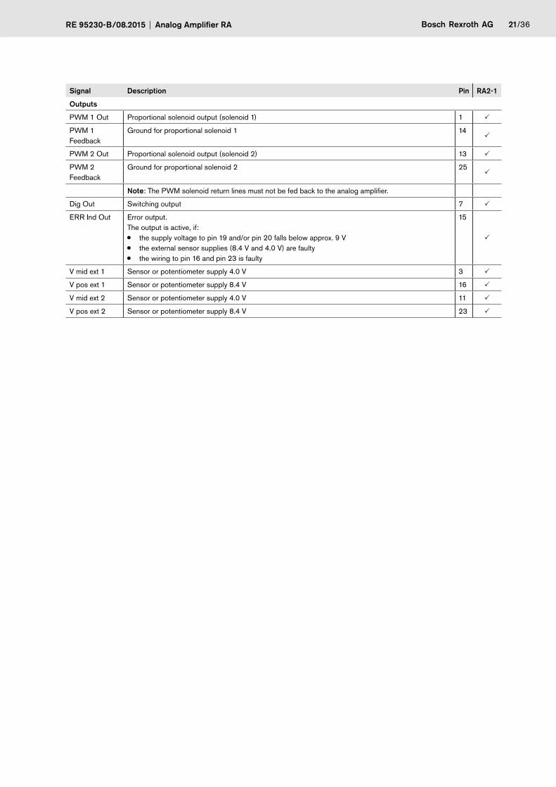
Signal Description Pin RA2-1
Outputs
PWM 1 Out Proportional solenoid output (solenoid 1) 1 P
PWM 1 Feedback
Ground for proportional solenoid 1 14P
PWM 2 Out Proportional solenoid output (solenoid 2) 13 P
PWM 2 Feedback
Ground for proportional solenoid 2 25P
Note: The PWM solenoid return lines must not be fed back to the analog amplifier.
Dig Out Switching output 7 P
ERR Ind Out Error output. The output is active, if: • the supply voltage to pin 19 and/or pin 20 falls below approx. 9 V • the external sensor supplies (8.4 V and 4.0 V) are faulty • the wiring to pin 16 and pin 23 is faulty
15
P
V mid ext 1 Sensor or potentiometer supply 4.0 V 3 P
V pos ext 1 Sensor or potentiometer supply 8.4 V 16 P
V mid ext 2 Sensor or potentiometer supply 4.0 V 11 P
V pos ext 2 Sensor or potentiometer supply 8.4 V 23 P
22/36 Bosch Rexroth AG Analog Amplifier RA RE 95230-B/08.2015
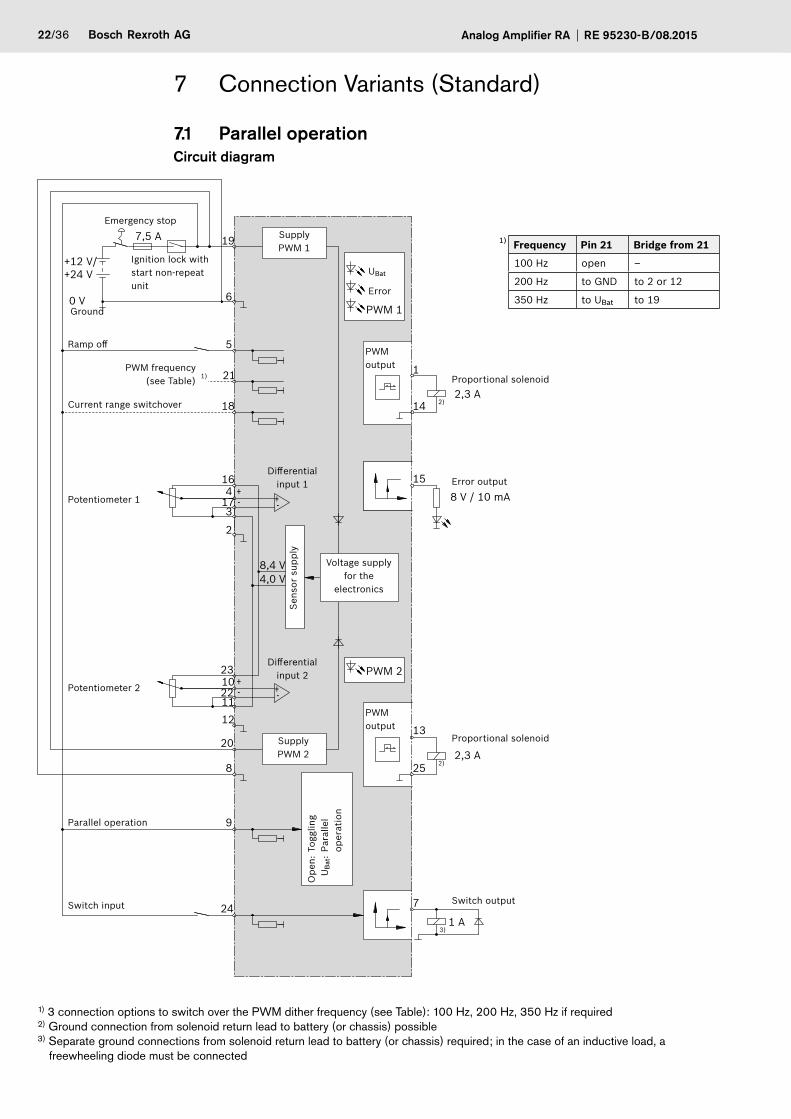
7 Connection Variants (Standard)
7.1 Parallel operationCircuit diagram
-+-+
-+
-+
19
6PWM 1
0 V
7,5 A
+12 V/+24 V
PWM 2
5
4
3
2
8
7
25
13
15
14 2)2,3 A
2)2,3 A
3)1 A
8 V / 10 mA
8,4 V4,0 V
1
9
21
18
16
17
1112
1023
22
20
24
1)
Emergency stop
Ignition lock with start non-repeat unit
Ground
Supply PWM 1
UBat
Error
Ramp off
PWM frequency (see Table)
Current range switchover
Potentiometer 1
Potentiometer 2
Parallel operation
Switch input
Ope
n: T
oggl
ing
U
Bat
: Pa
ralle
l op
erat
ion
Supply PWM 2
PWM output
Differential input 2
Differential input 1
Sens
or s
uppl
y
Voltage supply for the
electronics
PWM output
Proportional solenoid
Proportional solenoid
Error output
Switch output
1) Frequency Pin 21 Bridge from 21
100 Hz open –
200 Hz to GND to 2 or 12
350 Hz to UBat to 19
1) 3 connection options to switch over the PWM dither frequency (see Table): 100 Hz, 200 Hz, 350 Hz if required 2) Ground connection from solenoid return lead to battery (or chassis) possible 3) Separate ground connections from solenoid return lead to battery (or chassis) required; in the case of an inductive load, a freewheeling diode must be connected
Bosch Rexroth AGRE 95230-B/08.2015 Analog Amplifier RA 23/36
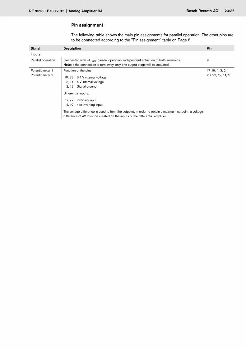
Pin assignment
The following table shows the main pin assignments for parallel operation. The other pins are to be connected according to the "Pin assignment" table on Page 8.
Signal Description Pin
Inputs
Parallel operation Connected with +UBatt: parallel operation, independent actuation of both solenoids.Note: If the connection is torn away, only one output stage will be actuated.
9
Potentiometer 1 Potentiometer 2
Function of the pins:
16, 23: 8.4 V internal voltage 3, 11: 4 V internal voltage 2, 12: Signal ground
Differential inputs:
17, 22: inverting input 4, 10: non inverting input
The voltage difference is used to form the setpoint. In order to obtain a maximum setpoint, a voltage difference of 4V must be created on the inputs of the differential amplifier.
17, 16, 4, 3, 2 23, 22, 12, 11, 10
24/36 Bosch Rexroth AG Analog Amplifier RA RE 95230-B/08.2015
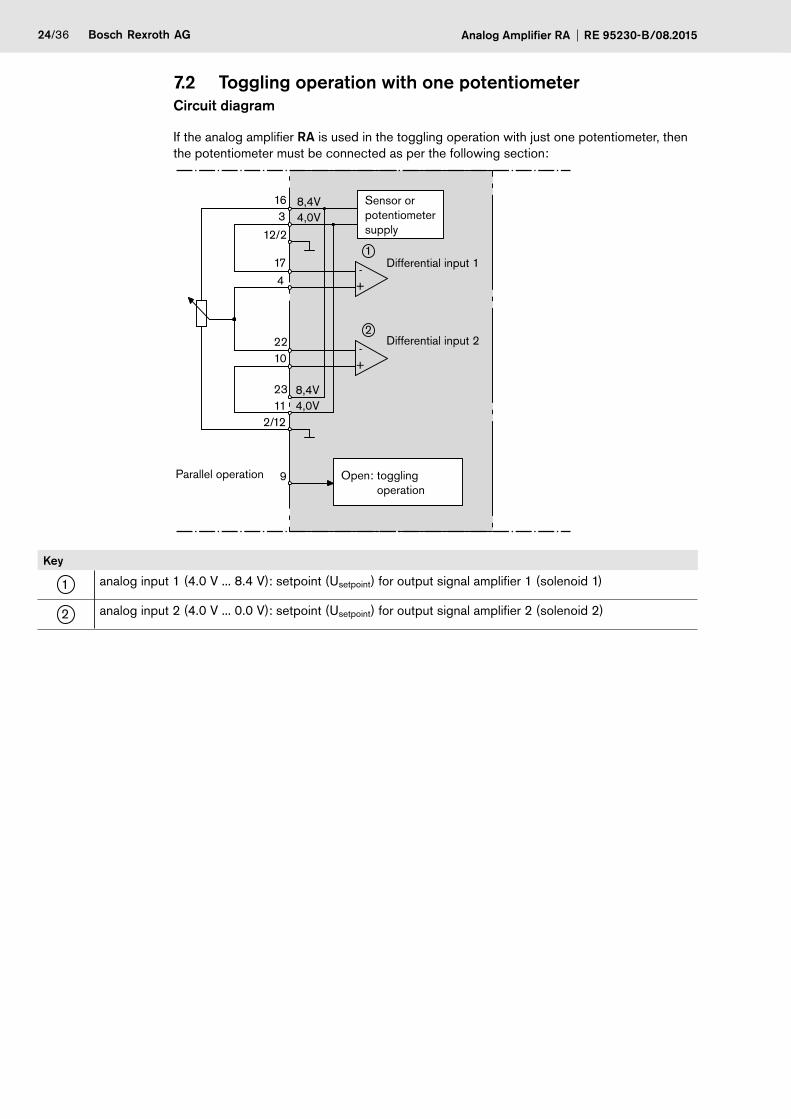
7.2 Toggling operation with one potentiometer Circuit diagram
If the analog amplifier RA is used in the toggling operation with just one potentiometer, then the potentiometer must be connected as per the following section:
+
+ -
2
-
1
4,0V8,4V16
3
1022
417
8,4V4,0V
23 11
2/12
9
12/2
Differential input 1
Differential input 2
Sensor or potentiometer supply
Parallel operation Open: toggling operation
Key
1 analog input 1 (4.0 V ... 8.4 V): setpoint (Usetpoint) for output signal amplifier 1 (solenoid 1)
2 analog input 2 (4.0 V ... 0.0 V): setpoint (Usetpoint) for output signal amplifier 2 (solenoid 2)
Bosch Rexroth AGRE 95230-B/08.2015 Analog Amplifier RA 25/36
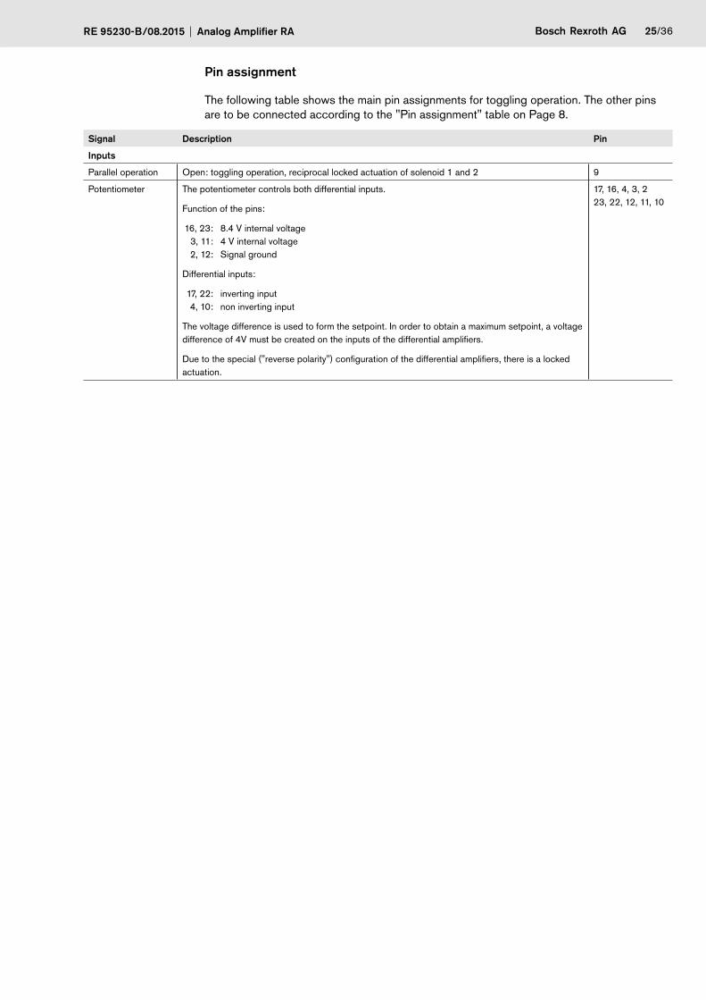
Pin assignment
The following table shows the main pin assignments for toggling operation. The other pins are to be connected according to the "Pin assignment" table on Page 8.
Signal Description Pin
Inputs
Parallel operation Open: toggling operation, reciprocal locked actuation of solenoid 1 and 2 9
Potentiometer The potentiometer controls both differential inputs.
Function of the pins:
16, 23: 8.4 V internal voltage 3, 11: 4 V internal voltage 2, 12: Signal ground
Differential inputs:
17, 22: inverting input 4, 10: non inverting input
The voltage difference is used to form the setpoint. In order to obtain a maximum setpoint, a voltage difference of 4V must be created on the inputs of the differential amplifiers.
Due to the special ("reverse polarity") configuration of the differential amplifiers, there is a locked actuation.
17, 16, 4, 3, 2 23, 22, 12, 11, 10
26/36 Bosch Rexroth AG Analog Amplifier RA RE 95230-B/08.2015
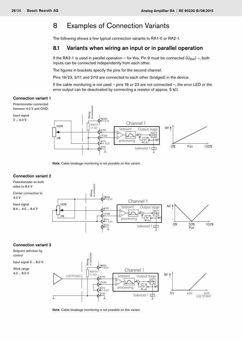
8 Examples of Connection Variants
The following shows a few typical connection variants to RA1-0 or RA2-1.
8.1 Variants when wiring an input or in parallel operation
If the RA2-1 is used in parallel operation – for this, Pin 9 must be connected (UBatt) –, both inputs can be connected independently from each other.
The figures in brackets specify the pins for the second channel.
Pins 16/23, 3/11 and 2/12 are connected to each other (bridged) in the device.
If the cable monitoring is not used – pins 16 or 23 are not connected –, the error LED or the error output can be deactivated by connecting a resistor of approx. 5 kW.
Connection variant 1Potentiometer connected between 4.0 V and GND.
Input signal 0 ... 4.0 V.
Wiri
ng
in c
onne
ctor
(23)
(10)
(22)
(11)
(12)
Channel 1Setpoint
processing
Output stage
Solenoid 1
approx. 5.1 kΩ
8.4V
4.0V
Note: Cable breakage monitoring is not possible on this variant.
Connection variant 2Potentiometer on both sides to 8.4 V
Center connection to 4.0 V
Input signal 8.4 ... 4.0 ... 8.4 V
(23)
(10)
(22)
(11)
(12)
Wiri
ng
in c
onne
ctor
Channel 1Setpoint
processing
Output stage
Solenoid 1
8.4V
4.0V
Connection variant 3Setpoint definition by control
Input signal 0 ... 8.0 V.
Work range 4.0 ... 8.0 V
(23)
(10)
(22)
(11)
(12)
Wiri
ng
in c
onne
ctor
Channel 1Setpoint
processing
Output stage
Solenoid 1
USETPOINT
USETPOINT
approx. 5.1 kΩ
8.4V
4.0V8.0V4.0V
Note: Cable breakage monitoring is not possible on this variant.
Bosch Rexroth AGRE 95230-B/08.2015 Analog Amplifier RA 27/36
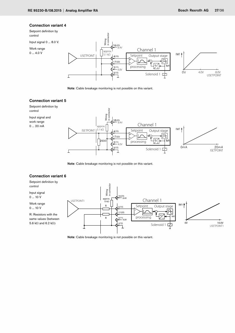
Connection variant 4Setpoint definition by control
Input signal 0 ... 8.0 V.
Work range 0 ... 4.0 V
(23)
(10)
(22)
(11)
(12)
Wiri
ng
in c
onne
ctor
Channel 1Setpoint
processing
Output stage
Solenoid 1
USETPOINT
USETPOINT
approx. 5.1 kΩ
8.4V
4.0V8.0V4.0V
Note: Cable breakage monitoring is not possible on this variant.
Connection variant 5Setpoint definition by control
Input signal and work range 0 ... 20 mA
(23)
(10)
(22)
(11)
(12)
Wiri
ng
in c
onne
ctor
Channel 1Setpoint
processing
Output stage
Solenoid 1
ISETPOINT
ISETPOINT
approx. 5.1 kΩ
8.4V
4.0V
Note: Cable breakage monitoring is not possible on this variant.
Connection variant 6Setpoint definition by control
Input signal 0 ... 10 V
Work range 0 ... 10 V
R: Resistors with the same values (between 5.6 kW and 6.2 kW)
+
-
IM1
ui
IM1
+
-
8.4V
4.0V
16
4
17
3
2 0V 10.0V
R
R
approx. 5 kΩ
(23)
(10)
(22)
(11)
(12)
Wiri
ng
in c
onne
ctor
Channel 1Setpoint
processing
Output stage
Solenoid 1
USETPOINT1
USETPOINT1
Note: Cable breakage monitoring is not possible on this variant.

28/36 Bosch Rexroth AG Analog Amplifier RA RE 95230-B/08.2015
8.2 Variants with independent wiring
Connection variant 7Parallel operation
Separate control with separate potentiometers and reciprocal modulation
Potentiometer connected between 8.4 V and 4.0 V.
Input signal 4.0 ... 8.4 V.
Alternative suggested circuit
Advantage: fewer wires
Parallel operation9
UBatt
Wiri
ng
in c
onne
ctor
Channel 2Setpoint
processing
Output stage
Solenoid 2
Channel 1Setpoint
processing
Output stage
Solenoid 1
8.4V
4.0V
8.4V
4.0V
8.4V
4.0V
4.0V
Note: If only one potentiometer supply line breaks, cable breakage will not be displayed.
Connection variant 8Setpoint definition by joystick
Input signal 0.5 ... 4.5 V
Work range Channel 1: 2.5 ... 4.5 V Channel 2: 0.5 ... 2.5 V
Note: The stated values for R1 and R2 can vary, as the voltage on pin 16 (8.4 V) is subject to tolerance and is additionally depen-dent on the total R1+R2.
The total of R1 and R2 must lie in the range of 2 kW to 5 kW
(2.4 kΩ
(1 kΩ
+
-
IM1
4.5V0.5V
ui
IM1
+
-
8.4V
4.0V
16
4
17
3
2
4.0V
12
11
22
10+
-
8.4V23
IM2i
+
u-
IM2
2.5V
2.5V0.5V 4.5V
R1
R2
UST
Wiri
ng
in c
onne
ctor
Channel 2Setpoint
processing
Output stage
Solenoid 2
USETPOINT
USETPOINT
Channel 1Setpoint
processing
Output stage
Solenoid 1 USETPOINT
Notes: – Cable breakage monitoring is not possible on this variant. – Due to the reduced signal stroke of 2 V in both directions, it is possible that the maximum current will not be reached.
Bosch Rexroth AGRE 95230-B/08.2015 Analog Amplifier RA 29/36
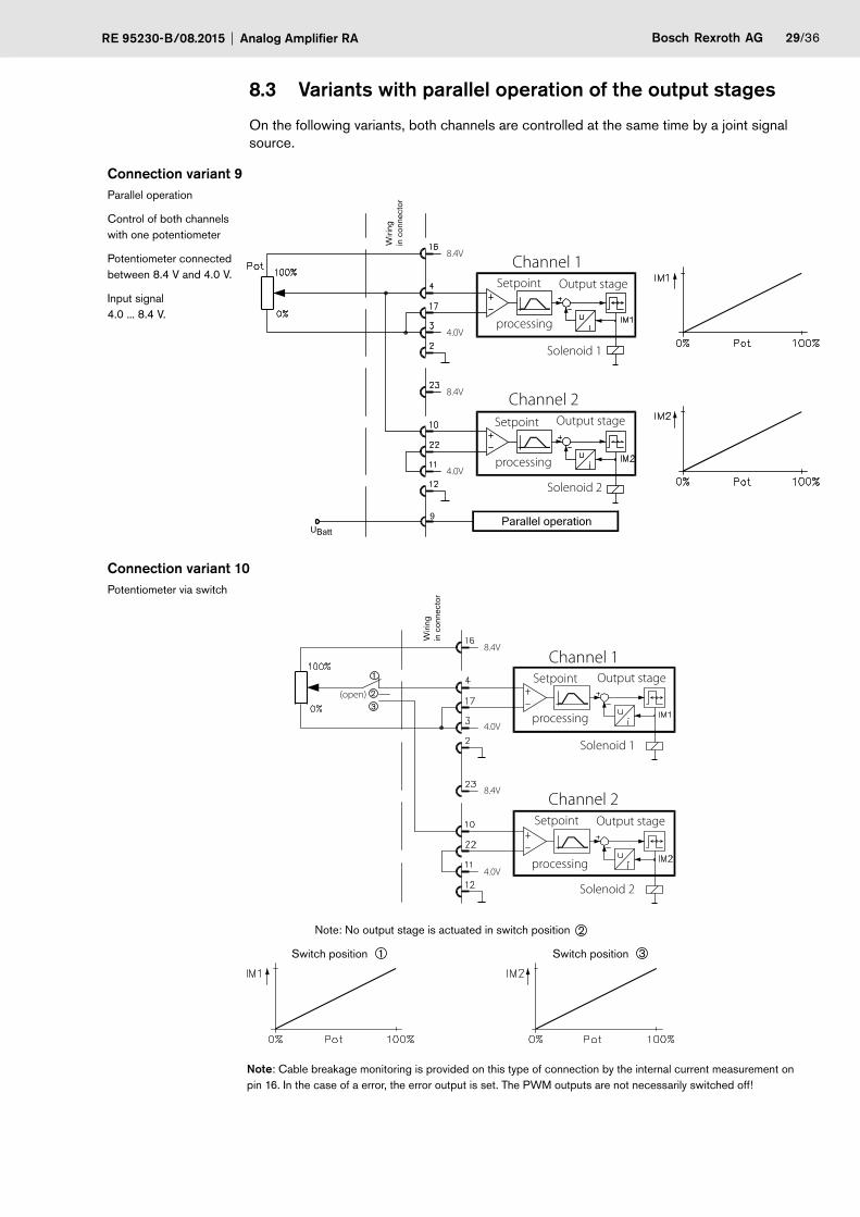
8.3 Variants with parallel operation of the output stages
On the following variants, both channels are controlled at the same time by a joint signal source.
Connection variant 9Parallel operation
Control of both channels with one potentiometer
Potentiometer connected between 8.4 V and 4.0 V.
Input signal 4.0 ... 8.4 V.
9
UBattParallel operation
Wiri
ng
in c
onne
ctor
Channel 2Setpoint
processing
Output stage
Solenoid 2
Channel 1Setpoint
processing
Output stage
Solenoid 1
8.4V
4.0V
8.4V
4.0V
Connection variant 10Potentiometer via switch
1
2
3
Switch position 1 Switch position 3
Note: No output stage is actuated in switch position 2
Wiri
ng
in c
onne
ctor
Channel 2Setpoint
processing
Output stage
Solenoid 2
Channel 1Setpoint
processing
Output stage
Solenoid 1
(open)
8.4V
4.0V
8.4V
4.0V
Note: Cable breakage monitoring is provided on this type of connection by the internal current measurement on pin 16. In the case of a error, the error output is set. The PWM outputs are not necessarily switched off!

30/36 Bosch Rexroth AG Analog Amplifier RA RE 95230-B/08.2015
Connection variant 11Parallel operation
Setpoint definition by control
Input signal 0 ... 10 V
Work range 0 ... 10 V
R: Resistors with the same values (between 2.7 kW and 3.0 kW)
9
UBattParallel operation
Wiri
ng
in c
onne
ctor
Channel 2Setpoint
processing
Output stage
Solenoid 2
Channel 1Setpoint
processing
Output stage
Solenoid 1
USETPOINT
USETPOINT
USETPOINT
approx. 5.1 kΩ
8.4V
4.0V
8.4V
4.0V
10.0V
10.0V
Note: Cable breakage monitoring is not possible on this variant.
Bosch Rexroth AGRE 95230-B/08.2015 Analog Amplifier RA 31/36
9 Commissioning
This section gives you an overview of the main steps in commissioning and gives information about rectifying typical problems.
9.1 Defining parameters
CAUTION Risk of property damage and personal injury
As the parameters are defined when the electrics are switched on, it is possible for the machine/vehicle to move unintentionally and cause damage.
• Make sure that nobody is in the hazard area.
• Ensure that the machine/vehicle cannot move, if possible (e.g. by disconnecting the transmission or jacking up the vehicle).
The analog amplifier must be adjusted before commissioning, so that it supplies the desired setpoint current at its output where the setpoint signal is at 100%.
Proceed as follows to adjust the analog amplifier:
1 Turn the adjusting potentiometer on the RA for Imin and Imax fully to the left.
2 Set the setpoint potentiometer, or the joystick, the sensor or the appropriate signal source (in this document referred to as setpoint potentiometer) to 100% (maximum value).
3 Turn the adjusting potentiometer for Imin to the right, until there is a reaction from the pump, the motor, the valve or the drive.
4 Turn the adjusting potentiometer Imax to the right, until the desired reaction of the hydraulic function is reached.
Note The adjusting potentiometer Imax should not be turned any further to the right after achieving the desired reaction (quantity/speed/pressure etc.), as otherwise an unnecessarily high current will flow. In addition, where the setpoint potentiometer is reduced (<100%) the drive does not reduce immediately. Conversely, the maximum modulation already occurs before 100% of the setpoint definition.
The correct setting has been made, if the drive follows immediately when reducing the setpoint potentiometer from 100%.
5 To adjust the ramp times, first set the setpoint potentiometer to 0%. After the drive has come to a standstill, quickly turn it to 100%. Use the adjusting potentiometer tup to set the up ramp to the desired time.
6 To adjust the down ramp, turn the setpoint potentiometer quickly to 0% and then use the adjusting potentiometer tdown to set the desired time.
Note The ramp adjustment procedure may need to be repeated several times.
It may be possible that the initial reaction fails too much on ramp operation. In this case, it can be reduced by turning the adjusting potentiometer Imin to the left. Then the maximum modulation must be reset again, in that you set the setpoint potentiometer to 100% and then set the desired maximum modulation with the adjusting potentiometer Imax by turning it to the right.
32/36 Bosch Rexroth AG Analog Amplifier RA RE 95230-B/08.2015
9.2 Rectification of typical problems
This section gives you some information about rectifying problems which could occur during commissioning.
Note If, during operation, a malfunction or a error is detected, then always check the external wiring (fuse, voltage supply, cabling etc) first. If the malfunction or error can be clearly traced back to the analog amplifier, then this should be sent to Rexroth together with a brief description of the error and a sketch of the wiring.
• General functional impairments– Ensure that all the ground connections are connected according to specifications.
• Malfunctions in parallel operation– Ensure that the input parallel operation (pin 9) is connected.
• Machine produces too little power– Check the current range switchover (pin 18).– Check the settings for Imin and Imax.
• Proportional solenoids do not react– Ensure that the differential amplifier is correctly connected and that Imin and Imax are set
correctly.– Ensure that the supply voltage is present.– Ensure that both input voltages are connected on RA if two proportional solenoids are
used.
• Error output is set – Ensure that a resistor in the range of 2 kW ... 5 kW is connected to pins 16 or 23
(depending on connection variant).– There is a difference between the internal and external voltages (e.g. short circuit or
incorrect cabling of the potentiometer). Check the wiring harness.– The voltage on one of the output stages is below approx. 9 V.
9.3 Factory settings
The standard factory settings are as follows:
• 3 seconds ramp (up/down) on all four ramps
• 200 ... 600 mA (pin 18 not connected)
• 400 ... 1200 mA (pin 18 with +UBatt connected)
9.4 Repairs and replacement
• Opening and repairing the device may only be carried out by Rexroth.
• The proper disposal of the device (electronic component) must occur according to the appropriate nationally valid laws.
Note The analog amplifier is not subject to EU-RL2000/53/EEC(ELV) and EU-RL2002/96/EC(WEEE).

Bosch Rexroth AGRE 95230-B/08.2015 Analog Amplifier RA 33/36
9.5 Maintenance and cleaning
The analog amplifier is maintenance-free.
The case is not resistant to cleaning with high pressure and/or steam jet devices.

34/36 Bosch Rexroth AG Analog Amplifier RA RE 95230-B/08.2015

Bosch Rexroth AGRE 95230-B/08.2015 Analog Amplifier RA 35/36
Index
A
Adjusting potentiometer 6
B
Benefits 4Block circuit diagram 19
C
Cleaning 33Commissioning 31
Defining parameters 31Typical problems 32
Connection variants 22Additional 26Parallel operation 22Toggling operation 24
Connector assembly 10
D
Disposal 9
E
Exchange 32
F
Factory settings 32Features 4Functional description 4Function of the LEDs 6
I
Installation 9Connector assembly 10Installation position 9Mounting 10
Installation position 9
L
LEDs 6
M
Maintenance 33Meaning of the LEDs 6Mounting 10
O
Operating modes 5Parallel operation 22Toggling operation 24
P
Paint work 3Parallel operation 22Pin assignment 20Potentiometer 6Project planning notes 8
R
Repairs 32Reversing operation
see Toggling operation 24
S
Safety instructions 3
T
Toggling operation 24
U
Unpacking 9Usage 4
W
Welding work 3

36/36 Bosch Rexroth AG Analog Amplifier RA RE 95230-B/08.2015
© All rights reserved by Bosch Rexroth AG, also for the event of registration of industrial property rights. All powers of disposition, such as reproduction and forwarding rights with us.
The information contained herein is intended to serve purely as a product description. The information we have provided cannot be used as evidence of a particular aspect or of suitability for a particular purpose. This information does not release the user from his responsibility to perform his own assessments and tests. Please note that our products are subject to the natural processes of aging and wear.
We reserve the right to make changes.
Bosch Rexroth AGMobile ApplicationsGlockeraustrasse 489275 Elchingen, GermanyService Tel. +49 9352 40 50 [email protected]/mobilelektronik


![User Manual - Analog Metricanalogmetric.com/download/2A3 PP Amplifier User Manual.pdf · [2A3 Push-Pull Tube Amplifier ] Analog Metric 6 5. If no any abnormal events, turn off the](https://img.dokumen.tips/doc/110x75/5ae78f757f8b9a87048f854e/user-manual-analog-pp-amplifier-user-manualpdf2a3-push-pull-tube-amplifier-.jpg)