Embed Size (px)
Citation preview

Rev. 1.3 8/08 Copyright © 2008 by Silicon Laboratories AN148
AN148
MAGNETIC STRIPE READER
1. Introduction
Magnetic stripe readers (MSRs) are widely used inmany different applications such as point-of-saleterminals and key card readers. The C8051F330 iscapable of integrating MSR functionality in a very smallspace with few external components. The high-speed,high-resolution ADC, coupled with a fast controller coremakes this integration possible. This designdemonstrates a two-channel MSR function using theon-chip ADC to read information directly from themagnetic read head. Output can be viewed using aPC’s terminal program via an RS-232 connection.
2. MSR Background
There are a number of different formats used forencoding information on magnetic stripes, and manydifferent types of card readers available. This designdemonstrates a swipe-type reader that reads Track 1and Track 2 of cards encoded using the ISO/IEC-7811standard. A firmware example for reading Track 1, 2,and 3 is also provided.
2.1. EncodingThe encoding format used by the ISO/IEC-7811standard is known as “F2F” or “Aiken Biphase”encoding. The F2F encoding format allows the serialdata to be self-clocking. Bits are encoded serially on themagnetic stripe using a series of magnetic fluxtransitions. Each bit of data on a track has a fixedphysical length on the magnetic stripe. Flux transitionsare located at the edge of each bit, and also in thecenter of each “1” bit. As the stripe passes the magneticread head, the flux transitions on the stripe areconverted into a series of alternating positive andnegative pulses, as shown in Figure 1. Afterdetermining which flux transitions represent the edgesof a bit, ones and zeros can be differentiated by thepresence or absence of a pulse in the center of the bit.
2.2. Data FormatThe data format specified by ISO/IEC-7811 encodes 7-bit (6 bits + parity) characters on Track 1, and 5-bit (4 bits + parity) decimal characters on Track 2. Track 3may contain 7-bit or 5-bit encoding, depending on thecard. Characters are written to the stripe LSB-first, withthe parity bit written last. All tracks contain leading andtrailing zeros at the ends of the stripe to aid the clockrecovery process. When read in the forward direction, atypical track contains information in the following order:
1. Clocking zeros
2. A start sentinel character
3. Data characters
4. An end sentinel character
5. A longitudinal redundancy check character
6. Clocking zeros
A number of error-checking features are included toensure accurate reads of the stripe information:
The Start Sentinel (SS) and End Sentinel (ES) characters are unique characters which signal the beginning and the end of the data encoded on the stripe. The SS and ES characters are not allowed as part of the data segment.
A Longitudinal Redundancy Check (LRC) character is included after the ES. The LRC is the result of an XOR operation on all characters in the track (including the SS and ES, but not the LRC character itself).
Relevant DevicesThis application note applies to the following devices:C8051F330
FLASH 3.7k/7.5kBytes
50%
RAM 402/768Bytes
53%
Port I/O11/17Pins
65%
Device Utilization

AN148
2 Rev. 1.3
Figure 1. Magnetic Stripe Encoding
All characters, including the SS, ES, and LRC, include a parity bit. Odd parity is used, meaning that the number of “1” bits in each character is odd when the parity bit is included.
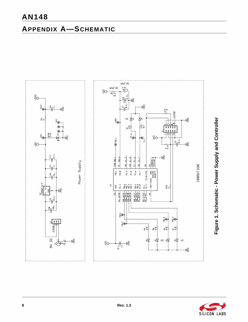
3. HardwareThe schematic and layout for this design can be foundin "Appendix A—Schematic‚" on page 8 and "AppendixB—Layout‚" on page 10, respectively. The designincludes circuitry for the core MSR function, as well aspower supply and RS-232 components. Although thereference design uses a two-track reader, there areprovisions for connecting a reader with three tracks.
3.1. Power SupplyPower can be supplied to the board using a 9 V dcadaptor connected to the 2.1 x 5.5 mm center-positivejack provided (P1). Power for the board circuitry isderived using a 3.3 V LDO regulator.
3.2. Analog InputsThe magnetic read heads are each connected directlyto one of the C8051F330’s differential ADC inputchannels. The magnetic head signals are filtered with asmall capacitor, and biased to the ground plane. Noadditional components are necessary.
3.3. Voltage ReferenceSignal levels from the magnetic read heads can be aslittle as a few millivolts. The on-chip voltage reference isused in this design. To enhance the signal detectioncapabilities of the device, the voltage reference for the10-bit ADC can be set as low as 1 V. There areplaceholders on the schematic and layout for resistorswhich will divide the 3.3 V supply down to 1 V.
3.4. RS-232 CircuitryAn RS-232 transceiver is included on-board for dataoutput purposes. The board can be connected directlyto a PC’s COM port using an RS-232 serial cable. Datais transferred at 115.2 kbps using 8 data bits, no Paritybit, and one Stop bit (8-N-1).
4. Software
The firmware listings can be found in "Appendix E—Firmware Listing For 2-Channel Example‚" on page 15and "Appendix F—Firmware Listing For 3-ChannelExample‚" on page 44. The provided firmware has beendeveloped using the Keil “C” compiler and the SiliconLabs IDE. The two-track solution is described in detail inthe following sections. The three-track firmwareexample is identical from an algorithmic standpoint.Differences between the two versions of the firmwareare listed at the end of this section.
The main structure of the firmware is relatively simple.After initializing the necessary device peripherals, thecontroller begins sampling ADC data, waiting for fluxtransitions at regular intervals. During the card swipe,the processor performs the F2F decoding and storesrecognized bits into RAM. After a swipe has finished,the stored data is then decoded and checked for errors.Decoded data is output to the UART, and the controllerwaits for another card swipe.
4.1. ADC SamplingThe ADC is configured to sample at 200 ksps usingTimer 2. Track 1 is sampled twice as often as Track 2,for an effective throughput of 133 ksps on Track 1 and67 ksps on Track 2. An exponential averaging techniqueis applied to the data to filter the signal prior to the signaldetection algorithm. Filtering increases the effectiveresolution of the ADC by reducing noise, and aids in thedetection of smaller read head signals.
N S S N N S S N N SMagnetic Stripe N S
Read Head Signal
0 0 0Decoded Data 1

AN148
Rev. 1.3 3
4.2. Signal DetectionSignal detection is performed by finding the minimumand maximum peaks in the filtered data that correspondto the pulse locations from the read head. See Figure 2.A moving comparison window allows local peak valuesto be recognized and time-stamped. The size of thecomparison window is controlled by the THRESHOLD1and THRESHOLD2 constants in firmware. Largervalues provide more noise rejection, while smallervalues allow weaker signals to be detected. The timebetween minimum and maximum peak values iscomputed and recorded after each pulse is detected.This information is used to synchronize with the bitstream and to discern between ones and zeros.
4.3. SynchronizationTo synchronize with the stream of clocking zeros, it isinitially assumed that all detected pulses are located atclock edges. During this phase of synchronization, thesoftware detects and counts zero bits, as shown inFigure 3. Three of the pulse timing values (Tbit) aresummed, and then divided by 2 and 4 to provide 150%and 75% timing thresholds, respectively. When Z_LIMIT(Zero Limit) consecutive timing values fall between the75% and 150% thresholds (i.e., when the softwaredetects Z_LIMIT zeros in a row), the algorithm begins tolook for the first "1" in the bit stream. When a "1" isdetected, the synchronization is complete. The first "1"is recorded to the data buffer and the software beginsthe data collection process.
Figure 2. Signal Detection
LimitWindow
PulseDetection
+
-

AN148
4 Rev. 1.3
4.4. Collecting DataDuring the data collection process, the clock edgetiming is continuously monitored, so that the algorithmcan adapt to variations in card swipe speed. The 75%threshold is re-calculated every three pulses. At eachvalid pulse from the magnetic head, the timinginformation is compared with the 75% threshold todetermine if the pulse occurred at the center or the edgeof a bit. Whenever a pulse occurs at the edge of a bit, a"1" or a "0" is recorded to the data buffer for the track. A"1" is recorded to the data buffer when a pulse wasdetected in the center of the most recent bit (i.e., when apulse was detected below the 75% threshold). If nopulse was detected within the bit, a "0" is recorded.When the conversion counter reaches 4096, the datacollection process is halted. The raw data is thendecoded and checked for errors. Figure 4 shows howthe detected pulses are recorded into the data buffer.
4.5. Decoding the Raw DataThe first step in decoding the raw data is to determinewhich direction (forward or reverse) the card wasswiped. To find the read direction, the decodingalgorithm looks for a start sentinel (SS) character at thebeginning and the end of the data set. If the SS is foundat the beginning of the data and not found at the end of
the data, the track is decoded in the forward direction. Ifthe SS is found at the end of the data and not found atthe beginning of the data, the track is decoded in thereverse direction. In the special case where the SS isfound at both ends of the data set, one of these SScharacters is actually the LRC. The routine then readsthe next forward character in reverse, and compares itwith the end sentinel (ES). If this character matches theES, data is decoded in the reverse direction. Otherwise,data is decoded in the forward direction.
If the SS is not found at either end of the data set, thedecoding algorithm looks at a character starting with thenext "1" bit in both directions and repeats the process.
For data collected in the forward direction, the bits arestored in the raw collection array LSB-first. The forwarddecode algorithm begins at the MSB of the rawcollection array and unpacks the data into bytes in theASCII array, until all data has been unpacked.
For data collected in the reverse direction, the bits arestored in the raw collection array MSB-first. The reversedecode algorithm begins by finding the location of thelast "1" bit in the raw array. Working backward throughthe array, the bits are copied into bytes in the ASCIIarray until all data has been unpacked.
Figure 3. Synchronization with Data Stream
Figure 4. Recording Data
4.6. Error Checking When data has been decoded into ASCII characters,
T75%
T150%
'0' Detected,Increase Zero
Count
PulseDetection
TBIT
+
-
Z_LIMITReached
First '1'Detected
Record '1'to Buffer
T75%
T75%
PulseDetection
+
-
T75%
0 0 1 1 0 1Recorded Data
T75% T75% T75% T75%

AN148
Rev. 1.3 5
the firmware checks the data for three types of errors:
Parity Check: Each character is checked individually to ensure that it has odd parity. The parity check sums the number of “1"s in the character’s data bits and determines if the parity bit should be a "1" or a "0" to make the sum odd. If the parity bit does not match the determined value, a parity error has occurred.
SS and ES Check: Data is checked to ensure that a Start Sentinel and an End Sentinel are both present. Any data stream that does not include a SS and an ES in the correct places was not read correctly.
LRC Check: As they are scanned for parity errors, each character’s data bits are XORed until the ES is reached (this check includes both the SS and ES characters). The result of the XOR function is compared with the LRC character to determine if an LRC error has occurred.
If no errors are detected, the decoded data is output,and the firmware prepares for another read.
4.7. OutputData is output through the UART on the device at115,200 Baud. The data format is 8 data bits, no paritybit, and 1 stop bit. The decoded data is converted toASCII before it is sent to the UART so that it can beeasily viewed. There are two different output modesdefined in the software. The modes are controlled by
conditional compilation using the constant DEBUG.
If DEBUG is set to "0", decoded track data will be outputas shown in Figure 5. Track data is output only if noerrors were detected for the track. The output will beginwith the Start Sentinel character and end with the EndSentinel character followed by the LRC. The StartSentinel for Track 1 is represented with the character“%”. For Track 2, the Start Sentinel is represented bythe character “;”. The End Sentinel for both tracks isrepresented by the character “?”.
If DEBUG is set to "1", the data output appears asshown in Figure 6. In this mode, data is output for bothtracks, regardless of whether an error occurred. Thedecoded data appears as when DEBUG is set to "0".The decoded data is followed by the raw data for thetrack. The raw data is displayed as a very longhexadecimal number. With the exception of the first byte(which is set to 0x00), the information displayed is thedata that was recorded during the card swipe.
In either output mode, the dual-color LEDs (D4 and D3)will give an indication of whether any errors weredetected in the collected data. D4 is used to indicate thestatus of Track 1, and D3 is used to indicate the statusof Track 2. During a card swipe, the diode will light bothred and green, to indicate a card swipe in progress. Ifthe data collection was successful and no errors weredetected, only the green LED will remain on. If errorswere detected, only the red LED will remain on.
Figure 5. Example Output when DEBUG = "0"
%B0123456789101112^SCHMOE/JOSEPH X^01020304050607080910?8;0123456789101112=01020304050607080910?:

AN148
6 Rev. 1.3
Figure 6. Example Output When DEBUG = "1"
4.8. Differences Between 2-Track and 3-Track Firmware
For the most part, the two firmware examples areidentical, with necessary variables and code added tohandle the third track. The three-track firmware has thefollowing notable differences from the two-track versiondescribed in the preceding sections:
• Two additional pins are used for analog input of Track 3
• Two additional pins are used to drive the dual-color LED (D1) for Track 3 status information.
• A conditional compilation constant has been added to allow the code to be compiled for either 5-bit or 7-bit encoding on the magnetic stripe. When T3_5BIT is cleared to "0", 7-bit encoding is used, and when T3_5BIT is set to "1", 5-bit encoding is used.
• Track 1 and Track 3 are sampled at an effective 80 ksps, while Track 2 is sampled at an effective 40 ksps.
Testing
DATA CH1:%B0123456789101112^SCHMOE/JOSEPH X^01020304050607080910?8END DATA CH1
RAW COLLECTION CH1:0x00A28C2454B90AD469D46CC8A122C58A95F67C42EDFAA5E557ACF4838B0239F048A11284C810A84A811A04EA10684991427C1A00000000END RAW CH1
DATA CH2:;0123456789101112=01020304050607080910?:END DATA CH2
RAW COLLECTION CH2:0x00D0608C92ADE0A700C210458300A039090350B43C08833807EB000000END RAW CH2
No Errors

AN148
Rev. 1.3 7
5. Operational Notes
Cards can be swiped through the reader in eitherdirection. When swiping a card it is essential that themagnetic stripe on the card makes contact with the readhead, and that the card remains level as it travelsthrough the reader, as shown in Figure 7. If the card istilted during the swipe, information may be lost.
6. Additional Information
Additional information on magnetic stripe readers andthe ISO/IEC-7811 standard can be found at thefollowing sources:
MagTek, I/O Interface for TTL Magnetic Stripe Readers, P/N 99875148, http://www.magtek.com.
International Standards Organization, ISO/IEC-7811, http://www.iso.org.
Figure 7. Swiping a Card through the Reader
Card Must Remain Level During Swipe
Magnetic Stripe Must FaceRead Head
AN148
8 Rev. 1.3
APPENDIX A—SCHEMATIC
Fig
ure
1. S
chem
atic
- P
ow
er S
up
ply
an
d C
on
tro
ller

AN148
Rev. 1.3 9
Figure 8. Schematic—Analog Input and RS-232 Output
AN148
10 Rev. 1.3
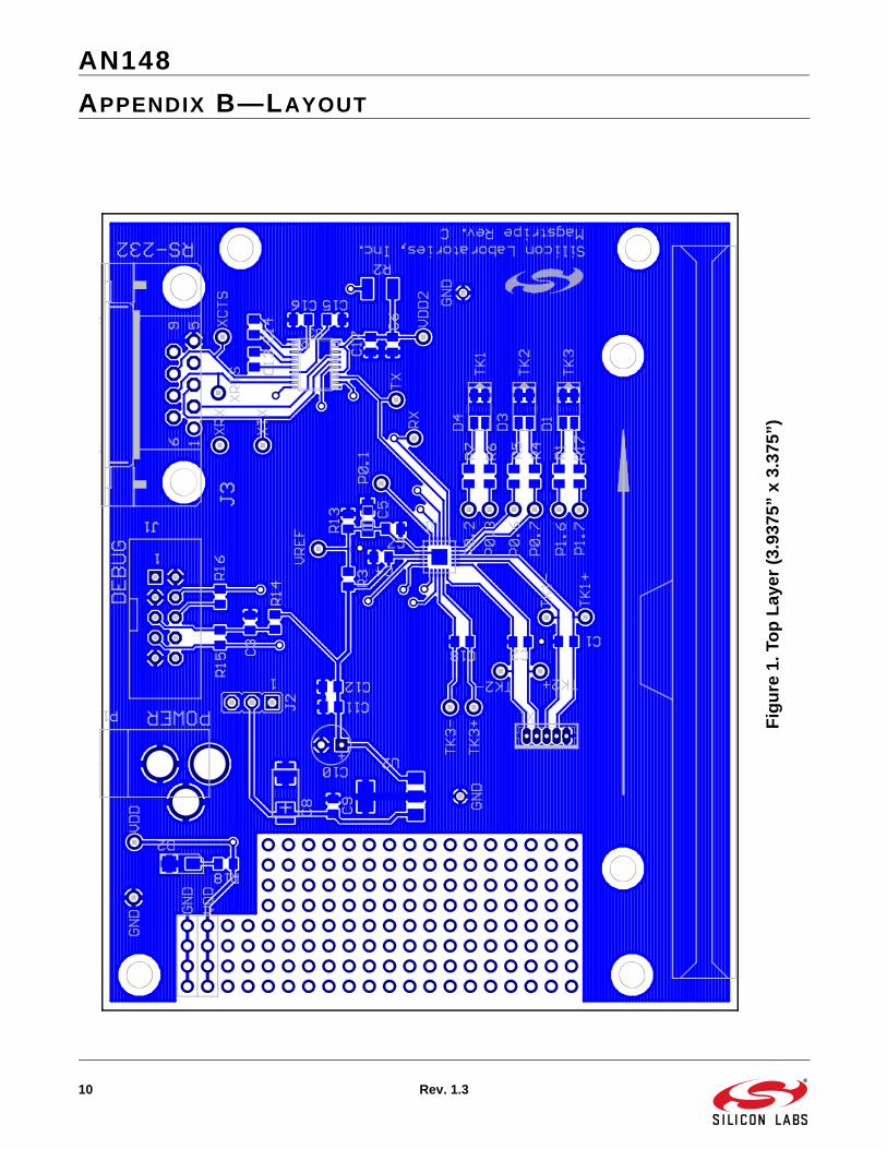
APPENDIX B—LAYOUT
Fig
ure
1. T
op
Lay
er (
3.93
75”
x 3.
375”
)

AN148
Rev. 1.3 11
Fig
ure
1. B
ott
om
Lay
er (
Mir
rore
d, 3
.937
5” x
3.3
75”)

AN148
12 Rev. 1.3
APPENDIX C—BILL OF MATERIALS
Qty Part Value Package Manufacturer
2 (2) C1, C2, C18† 150 pF 0805
10 (2) C3*, C4, C7, C9*, C12*, C13*, C14*, C15*, C16*, C17*
0.1 F 0805
1 (1) C5 4.7 F Tant. EIA Size A 3216
2 (0) C6*, C11* 1 F 0805
1 (0) C8* 10 uF Tant. EIA Size C 6032
1 (0) C10* 15 F Tant. Thru-Hole
3 (0) D1*†, D3*, D4* SML-LX1210SRSGC Lumex
1 (0) D2* LN1251C Panasonic
1 (0) J1* 2510-6002UB 0.1” Thru-Hole 3M
1 (0) J2* 1x3 Header 0.1” Thru-Hole
1 (0) J3* 747844-6 DB9_F AMP
1 (0) P1* RAPC722 2.1 x 5.5 mm SwitchCraft
3 (0) R1*†, R4*, R5*, R6*, R7*, R17*†, R18*
470 0805
1 (0) R2* 2 1210
1 (0) R3* (Not Populated) 4.75 k 0805
1 (0) R13* (Not Populated) 2.15 k 0805
3 (1) R14, R15*, R16* 1 k 0805
1 (1) U1 C8051F330 MLP20 Silicon Labs
1 (0) U2* LM2913IMP-3.3 SOT223 National Semiconductor
1 (0) U3* SP3223 TSSOP20 Sipex
1 (1) X1 53047-0510 1.25 mm Thru-Hole
Molex
1 (1) Magnetic Head Assy. 21047004 Magtek
( ) Denotes quantity of components necessary for 2-channel C8051F330 MSR function.* Denotes demonstration board components not required for C8051F330 MSR function.† Denotes additional components used in 3-channel C8051F330 MSR function.

AN148
Rev. 1.3 13
APPENDIX D—DEVICE UTILIZATION AND BOARD SPACE REQUIREMENTS
The device memory and peripheral requirements are shown in Table 1 and Table 2. Some peripherals such as theUART, Timer 1, and the Port I/O pins connected to the LED indicator are not essential to the MSR function, and canbe used for other purposes.
The PCB area required for the core MSR function can be estimated by totaling the area required by eachcomponent. Table 3 shows an estimation of the area required by each component, as well as the total arearequired to implement the MSR function. This area estimate does not include space required for connectors orPCB traces.
Table 1. Device Resource Usage for 2-Channel Example Code
Device Resources Used Available
Flash Memory Approx. 3.7 kB Approx. 3.8 kB
RAM 402 Bytes 366 Bytes
Port I/O 11 (5 Analog, 2 UART, 4 LEDs) 6 (12 w/o UART and LEDs)
10-Bit SAR ADC 2 Differential Inputs (4 Pins) Yes*
Timers Timer 1 (UART), Timer 2 (ADC) Timer 0, Timer 3
Serial Communications UART SMBus, SPI
10-Bit Current-Mode DAC No Yes
Comparator No Yes
3-Channel PCA No Yes
*Note: The ADC can be used for other purposes when card is not being read.
Table 2. Device Resource Usage for 3-Channel Example Code
Device Resources Used Available
Flash Memory Approx. 4.7 kB Approx. 2.8 kB
RAM 524 Bytes 244 Bytes
Port I/O 15 (7 Analog, 2 UART, 6 LEDs) 2 (10 w/o UART and LEDs)
10-Bit SAR ADC 3 Differential Inputs (6 Pins) Yes*
Timers Timer 1 (UART), Timer 2 (ADC) Timer 0, Timer 3
Serial Communications UART SMBus, SPI
10-Bit Current-Mode DAC No Yes
Comparator No Yes
3-Channel PCA No Yes
*Note: The ADC can be used for other purposes when card is not being read.

AN148
14 Rev. 1.3
Table 3. Estimated Component PCB Area
Device Area
(sq. inch)
Quantity Total Area
(sq. inch)
C8051F330 4 x 4 mm 20-pin MLP 0.025 1 0.025
4.7 F Tantalum Capacitor on VREF (3216, EIA Size A) 0.012 1 0.012
0.1 F Capacitors for Decoupling and Bypass (0805) 0.008 2 0.016
150 pF Filtering Capacitor (0805) (1 per channel) 0.008 2 (2 Ch)3 (3 Ch)
0.0160.024
1 k Pullup Resistor on /RST (0805) 0.008 1 0.008
Total Component Area (sq. inch) 2-Channel3-Channel
0.0770.085

AN148
Rev. 1.3 15
APPENDIX E—FIRMWARE LISTING FOR 2-CHANNEL EXAMPLE
//-----------------------------------------------------------------------------// MagStripeReaderF330_2CH.c//-----------------------------------------------------------------------------// Copyright 2004 Silicon Laboratories//// AUTH: BD// DATE: 3 MAR 04// VER: 2.0//// This program reads the magnetic stripe from a card written in the standard// ISO 2-channel format using F2F encoding. Read data is output to the UART// after being decoded.//// Target: C8051F33x// Tool chain: KEIL C51 7.06 / KEIL EVAL C51//
//-----------------------------------------------------------------------------// Includes//-----------------------------------------------------------------------------
#include <c8051f330.h> // SFR declarations for C8051F330
//-----------------------------------------------------------------------------// 16-bit SFR Definitions for ‘F33x//-----------------------------------------------------------------------------sfr16 TMR2RL = 0xca; // Timer2 reload valuesfr16 TMR2 = 0xcc; // Timer2 counter
//-----------------------------------------------------------------------------// Conditional Compilation CONSTANTS//-----------------------------------------------------------------------------
#define DEBUG 0 // Set to ‘1’ for extra information
//-----------------------------------------------------------------------------// Global CONSTANTS//-----------------------------------------------------------------------------
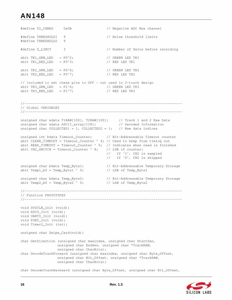
#define SYSCLK 24500000 // SYSCLK frequency in Hz#define BAUDRATE 115200 // Baud rate of UART in bps#define SAMPLE_RATE 200000 // Sample rate of ADC
#define T1_SS 0x45 // Start Sentinel + parity#define T1_ES 0x1F // End Sentinel + parity#define T1_BITS 7 // data + parity bit#define T1_CHPOS 0x08 // Positive ADC Mux channel#define T1_CHNEG 0x09 // Negative ADC Mux channel
#define T2_SS 0x0B // Start Sentinel + parity#define T2_ES 0x1F // End Sentinel + parity#define T2_BITS 5 // data + parity bit#define T2_CHPOS 0x0A // Positive ADC Mux channel
AN148
16 Rev. 1.3
#define T2_CHNEG 0x0B // Negative ADC Mux channel
#define THRESHOLD1 9 // Noise threshold limits#define THRESHOLD2 9
#define Z_LIMIT 3 // Number of Zeros before recording
sbit TK1_GRN_LED = P0^2; // GREEN LED TK1sbit TK1_RED_LED = P0^3; // RED LED TK1
sbit TK2_GRN_LED = P0^6; // GREEN LED TK2sbit TK2_RED_LED = P0^7; // RED LED TK2
// Included to set these pins to OFF - not used in 2-track designsbit TK3_GRN_LED = P1^6; // GREEN LED TK3sbit TK3_RED_LED = P1^7; // RED LED TK3
//-----------------------------------------------------------------------------// Global VARIABLES//-----------------------------------------------------------------------------
unsigned char xdata T1RAW[100], T2RAW[100]; // Track 1 and 2 Raw Dataunsigned char xdata ASCII_array[128]; // Decoded Informationunsigned char COLLECTED1 = 1, COLLECTED2 = 1; // Raw data indices
unsigned int bdata Timeout_Counter; // Bit-Addressable Timeout countersbit CLEAR_TIMEOUT = Timeout_Counter ^ 4; // Used to keep from timing outsbit READ_TIMEOUT = Timeout_Counter ^ 5; // Indicates when read is finishedsbit CH2_SWITCH = Timeout_Counter ^ 8; // LSB of counter: // If ‘1’, CH2 is sampled // If ‘0’, CH2 is skipped
unsigned char bdata Temp_Byte1; // Bit-Addressable Temporary Storagesbit Temp1_b0 = Temp_Byte1 ^ 0; // LSB of Temp_Byte1
unsigned char bdata Temp_Byte2; // Bit-Addressable Temporary Storagesbit Temp2_b0 = Temp_Byte2 ^ 0; // LSB of Temp_Byte2
//-----------------------------------------------------------------------------// Function PROTOTYPES//-----------------------------------------------------------------------------
void SYSCLK_Init (void);void ADC0_Init (void);void UART0_Init (void);void PORT_Init (void);void Timer2_Init (int);
unsigned char Swipe_Card(void);
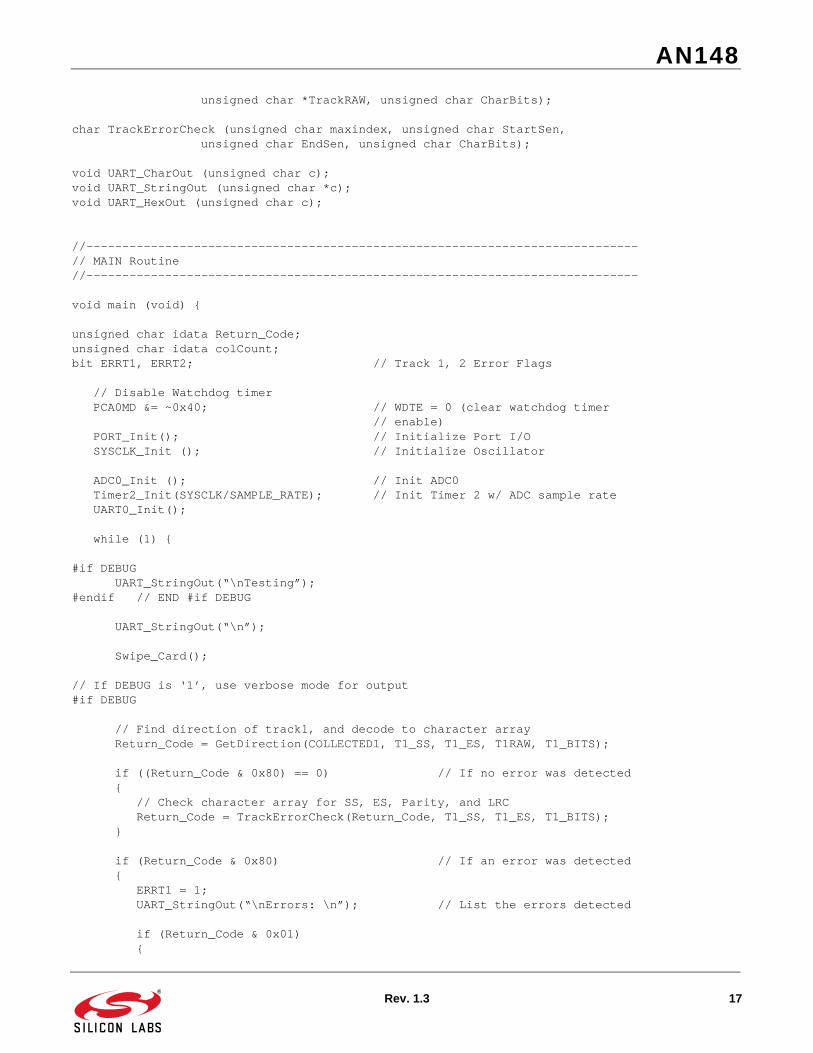
char GetDirection (unsigned char maxindex, unsigned char StartSen, unsigned char EndSen, unsigned char *TrackRAW, unsigned char CharBits);char DecodeTrackForward (unsigned char maxindex, unsigned char Byte_Offset, unsigned char Bit_Offset, unsigned char *TrackRAW, unsigned char CharBits);
char DecodeTrackBackward (unsigned char Byte_Offset, unsigned char Bit_Offset,
AN148
Rev. 1.3 17
unsigned char *TrackRAW, unsigned char CharBits);
char TrackErrorCheck (unsigned char maxindex, unsigned char StartSen, unsigned char EndSen, unsigned char CharBits);
void UART_CharOut (unsigned char c);void UART_StringOut (unsigned char *c);void UART_HexOut (unsigned char c);
//-----------------------------------------------------------------------------// MAIN Routine//-----------------------------------------------------------------------------
void main (void) {
unsigned char idata Return_Code;unsigned char idata colCount;bit ERRT1, ERRT2; // Track 1, 2 Error Flags
// Disable Watchdog timer PCA0MD &= ~0x40; // WDTE = 0 (clear watchdog timer // enable) PORT_Init(); // Initialize Port I/O SYSCLK_Init (); // Initialize Oscillator
ADC0_Init (); // Init ADC0 Timer2_Init(SYSCLK/SAMPLE_RATE); // Init Timer 2 w/ ADC sample rate UART0_Init();
while (1) {
#if DEBUG UART_StringOut(“\nTesting”);#endif // END #if DEBUG
UART_StringOut(“\n”);
Swipe_Card();
// If DEBUG is ‘1’, use verbose mode for output#if DEBUG
// Find direction of track1, and decode to character array Return_Code = GetDirection(COLLECTED1, T1_SS, T1_ES, T1RAW, T1_BITS);
if ((Return_Code & 0x80) == 0) // If no error was detected { // Check character array for SS, ES, Parity, and LRC Return_Code = TrackErrorCheck(Return_Code, T1_SS, T1_ES, T1_BITS); }
if (Return_Code & 0x80) // If an error was detected { ERRT1 = 1; UART_StringOut(“\nErrors: \n”); // List the errors detected
if (Return_Code & 0x01) {

AN148
18 Rev. 1.3
UART_StringOut(“\tStart Sentinel not found\n”); } if (Return_Code & 0x02) { UART_StringOut(“\tEnd Sentinel not found\n”); } if (Return_Code & 0x04) { UART_StringOut(“\tLRC incorrect\n”); } if (Return_Code & 0x08) { UART_StringOut(“\tParity error(s)\n”); }
UART_StringOut(“\nDATA CH1:\n”); for (colCount = 0; colCount < 128; colCount++) { UART_CharOut(0x20 + (ASCII_array[colCount]&0x3F)); UART_CharOut(0x30); } UART_CharOut(‘\n’); UART_StringOut(“END DATA CH1\n”); } else // No errors, print T1 data { ERRT1 = 0; UART_StringOut(“\nDATA CH1:\n”);
for (colCount = 0; colCount < Return_Code; colCount++) { UART_CharOut(0x20 + (ASCII_array[colCount]&0x3F)); ASCII_array[colCount] = 0x30; } UART_CharOut(‘\n’); UART_StringOut(“END DATA CH1\n”); }
// Print the RAW data for Track 1 UART_StringOut(“\nRAW COLLECTION CH1:\n0x”);
for (colCount = 0; colCount < COLLECTED1; colCount++) { UART_HexOut (T1RAW[colCount]); }
UART_CharOut(‘\n’); UART_StringOut(“END RAW CH1\n”);
// Find direction of track2, and decode to character array Return_Code = GetDirection(COLLECTED2, T2_SS, T2_ES, T2RAW, T2_BITS);
if ((Return_Code & 0x80) == 0) // If no error was detected { // Check character array for SS, ES, Parity, and LRC Return_Code = TrackErrorCheck(Return_Code, T2_SS, T2_ES, T2_BITS); }
if (Return_Code & 0x80) // If an error was detected

AN148
Rev. 1.3 19
{ ERRT2 = 1; UART_StringOut(“\nErrors: \n”); // List the errors detected
if (Return_Code & 0x01) { UART_StringOut(“\tStart Sentinel not found\n”); } if (Return_Code & 0x02) { UART_StringOut(“\tEnd Sentinel not found\n”); } if (Return_Code & 0x04) { UART_StringOut(“\tLRC incorrect\n”); } if (Return_Code & 0x08) { UART_StringOut(“\tParity error(s)\n”); }
UART_StringOut(“\nDATA CH2:\n”); for (colCount = 0; colCount < 128; colCount++) { UART_CharOut(0x30 + (ASCII_array[colCount]&0x0F)); ASCII_array[colCount] = 0x30; } UART_CharOut(‘\n’); UART_StringOut(“END DATA CH2\n”); } else // No errors, print T2 data { ERRT2 = 0; UART_StringOut(“\nDATA CH2:\n”);
for (colCount = 0; colCount < Return_Code; colCount++) { UART_CharOut(0x30 + (ASCII_array[colCount]&0x0F)); ASCII_array[colCount] = 0x30; } UART_CharOut(‘\n’); UART_StringOut(“END DATA CH2\n”); }
// Print the RAW data for Track 2 UART_StringOut(“\nRAW COLLECTION CH2:\n0x”);
for (colCount = 0; colCount < COLLECTED2; colCount++) { UART_HexOut (T2RAW[colCount]); }
UART_CharOut(‘\n’); UART_StringOut(“END RAW CH2\n”);
// Signal Error / OK with LEDs if (!ERRT1) { TK1_RED_LED = 0;

AN148
20 Rev. 1.3
TK1_GRN_LED = 1; } else { TK1_RED_LED = 1; TK1_GRN_LED = 0; } // Signal Error / OK with LEDs if (!ERRT2) { TK2_RED_LED = 0; TK2_GRN_LED = 1; } else { TK2_RED_LED = 1; TK2_GRN_LED = 0; }
#endif // END #if DEBUG
// If DEBUG is ‘0’, only output valid track info#if !DEBUG
// Find direction of track1, and decode to character array Return_Code = GetDirection(COLLECTED1, T1_SS, T1_ES, T1RAW, T1_BITS);
if ((Return_Code & 0x80) == 0) // If no error was detected { // Check character array for SS, ES, Parity, and LRC Return_Code = TrackErrorCheck(Return_Code, T1_SS, T1_ES, T1_BITS); }
if (Return_Code & 0x80) // If an error was detected { // set the error bit ERRT1 = 1; } else // Otherwise print Track 1 { ERRT1 = 0; for (colCount = 0; colCount < Return_Code; colCount++) { UART_CharOut(0x20 + (ASCII_array[colCount]&0x3F)); ASCII_array[colCount] = 0x30; } UART_CharOut(‘\n’); }
// Find direction of track2, and decode to character array Return_Code = GetDirection(COLLECTED2, T2_SS, T2_ES, T2RAW, T2_BITS);
if ((Return_Code & 0x80) == 0) // If no error was detected { // Check character array for SS, ES, Parity, and LRC Return_Code = TrackErrorCheck(Return_Code, T2_SS, T2_ES, T2_BITS); }

AN148
Rev. 1.3 21
if (Return_Code & 0x80) // If an error was detected { // set the error bit ERRT2 = 1; } else // Otherwise print Track 2 { ERRT2 = 0; for (colCount = 0; colCount < Return_Code; colCount++) { UART_CharOut(0x30 + (ASCII_array[colCount]&0x0F)); ASCII_array[colCount] = 0x30; } UART_CharOut(‘\n’); }
// Signal Error / OK with LEDs if (!ERRT1) { TK1_RED_LED = 0; TK1_GRN_LED = 1; } else { TK1_RED_LED = 1; TK1_GRN_LED = 0; } // Signal Error / OK with LEDs if (!ERRT2) { TK2_RED_LED = 0; TK2_GRN_LED = 1; } else { TK2_RED_LED = 1; TK2_GRN_LED = 0; }
#endif // END #if !DEBUG
} // END while(1)} // END main()
//-----------------------------------------------------------------------------// Initialization Subroutines//-----------------------------------------------------------------------------
//-----------------------------------------------------------------------------// PORT_Init//-----------------------------------------------------------------------------//// Configure the Crossbar and GPIO ports.//// P0.0 - VREF Input (analog, skipped)// P0.2 - TK1 Green LED (push-pull, skipped)// P0.3 - TK1 Red LED (push-pull, skipped)// P0.4 - UART TX (push-pull)// P0.5 - UART RX (open drain)

AN148
22 Rev. 1.3
// P0.6 - TK2 Green LED (push-pull, skipped)// P0.7 - TK2 Red LED (push-pull, skipped)// P1.0 - Channel 1+ (analog, skipped)// P1.1 - Channel 1- (analog, skipped)// P1.2 - Channel 2+ (analog, skipped)// P1.3 - Channel 2- (analog, skipped)// P1.6 - TK3 Green LED (push-pull, skipped)// P1.7 - TK3 Red LED (push-pull, skipped)//
void PORT_Init (void){ P0MDOUT |= 0xDC; // enable TX and LEDs as push-pull out
P0MDIN &= ~0x01; // VREF analog in P1MDIN &= ~0x0F; // Enable P1.0 through 1.3 as analog in P1MDOUT |= 0xC0; // P1.6, 1.7 Push-pull output
P0SKIP |= 0xCD; // Skip VREF pin and LED Outputs P1SKIP |= 0xCF; // Skip Analog Inputs and LED Outputs
XBR0 = 0x01; // Enable UART on P0.4(RX) and P0.5(TX) XBR1 = 0x40; // Enable crossbar and enable // weak pull-ups
TK1_RED_LED = 0; // Turn all LEDs off TK1_GRN_LED = 0; TK2_RED_LED = 0; TK2_GRN_LED = 0; TK3_RED_LED = 0; TK3_GRN_LED = 0;}
//-----------------------------------------------------------------------------// SYSCLK_Init//-----------------------------------------------------------------------------//// This routine initializes the system clock to use the internal oscillator// at its maximum frequency, enables the Missing Clock Detector and VDD// monitor.//
void SYSCLK_Init (void){ OSCICN |= 0x03; // Configure internal oscillator for // its maximum frequency RSTSRC = 0x06; // Enable missing clock detector and // VDD Monitor}
//-----------------------------------------------------------------------------// ADC0_Init//-----------------------------------------------------------------------------//// Configure ADC0 to use Timer 2 as conversion source, and to initially point// to Channel 2. Disables ADC end of conversion interrupt. Leaves ADC// disabled.//void ADC0_Init (void)

AN148
Rev. 1.3 23
{ ADC0CN = 0x02; // ADC0 disabled; Normal tracking // mode; ADC0 conversions are initiated // on timer 2
AMX0P = T1_CHPOS; // Channel 1+ AMX0N = T1_CHNEG; // Channel 1-
ADC0CF = (SYSCLK/3000000) << 3; // ADC conversion clock <= 3MHz
ADC0CF &= ~0x04; // Right-Justify data REF0CN = 0x03; // VREF = P0.0 internal VREF, bias // generator is on.
}
//-----------------------------------------------------------------------------// UART0_Init//-----------------------------------------------------------------------------//// Configure the UART0 using Timer1, for <BAUDRATE> and 8-N-1.//void UART0_Init (void){ SCON0 = 0x10; // SCON0: 8-bit variable bit rate // level of STOP bit is ignored // RX enabled // ninth bits are zeros // clear RI0 and TI0 bits if (SYSCLK/BAUDRATE/2/256 < 1) { TH1 = -(SYSCLK/BAUDRATE/2); CKCON &= ~0x0B; // T1M = 1; SCA1:0 = xx CKCON |= 0x08; } else if (SYSCLK/BAUDRATE/2/256 < 4) { TH1 = -(SYSCLK/BAUDRATE/2/4); CKCON &= ~0x0B; // T1M = 0; SCA1:0 = 01 CKCON |= 0x01; } else if (SYSCLK/BAUDRATE/2/256 < 12) { TH1 = -(SYSCLK/BAUDRATE/2/12); CKCON &= ~0x0B; // T1M = 0; SCA1:0 = 00 } else { TH1 = -(SYSCLK/BAUDRATE/2/48); CKCON &= ~0x0B; // T1M = 0; SCA1:0 = 10 CKCON |= 0x02; }
TL1 = TH1; // init Timer1 TMOD &= ~0xf0; // TMOD: timer 1 in 8-bit autoreload TMOD |= 0x20; TR1 = 1; // START Timer1 TI0 = 1; // Indicate TX0 ready}
//-----------------------------------------------------------------------------// Timer2_Init//-----------------------------------------------------------------------------//// Configure Timer2 to auto-reload at interval specified by <counts> (no

AN148
24 Rev. 1.3
// interrupt generated) using SYSCLK as its time base.//void Timer2_Init (int counts){ TMR2CN = 0x00; // STOP Timer2; Clear TF2H and TF2L; // disable low-byte interrupt; disable // split mode; select internal timebase CKCON |= 0x10; // Timer2 uses SYSCLK as its timebase
TMR2RL = -counts; // Init reload values TMR2 = TMR2RL; // Init Timer2 with reload value}
//-----------------------------------------------------------------------------// Support Subroutines//-----------------------------------------------------------------------------
//-----------------------------------------------------------------------------// Swipe_Card//-----------------------------------------------------------------------------//// This routine performs the signal detection and data collection when a card// is swiped through the reader for Track 1 and 2. Interrupts should be// turned off when this routine runs for optimal performance.//
unsigned char Swipe_Card(void){unsigned char data zerocount1; // Zero counter - Track 1unsigned char data bytecount1; // Raw data counter - TK 1unsigned char data zerocount2; // Zero counter - Track 2unsigned char data bytecount2; // Raw data counter - TK 2
char data runningsum1 = 0, rsum1_div = 0; // Filtering variableschar data runningsum2 = 0, rsum2_div = 0;
// Minimum / Maximum and // next peak valueschar data localmax1 = 0, localmin1 = 0, next_peak1 = 0;char data localmax2 = 0, localmin2 = 0, next_peak2 = 0;
char data ADC_DATA; // Raw ADC Data (low byte)
unsigned int data cyclecount1, cyclecount2; // Cycle counters
unsigned int maincycle; // Main time stamp for // ADC conversions
unsigned int data maxtime1, mintime1; // Min / Max time stampsunsigned int data maxtime2, mintime2;
unsigned char data cycleindex1; // Index for # of cyclesunsigned char data cycleindex2; // present in sumunsigned int data cyclesum1 = 0; // Sum over 3 cyclesunsigned int data cyclesum2 = 0;unsigned int data CP75pct1 = 0, CP150pct1 = 0; // 75% and 150% comparisonunsigned int data CP75pct2 = 0, CP150pct2 = 0; // values
AN148
Rev. 1.3 25
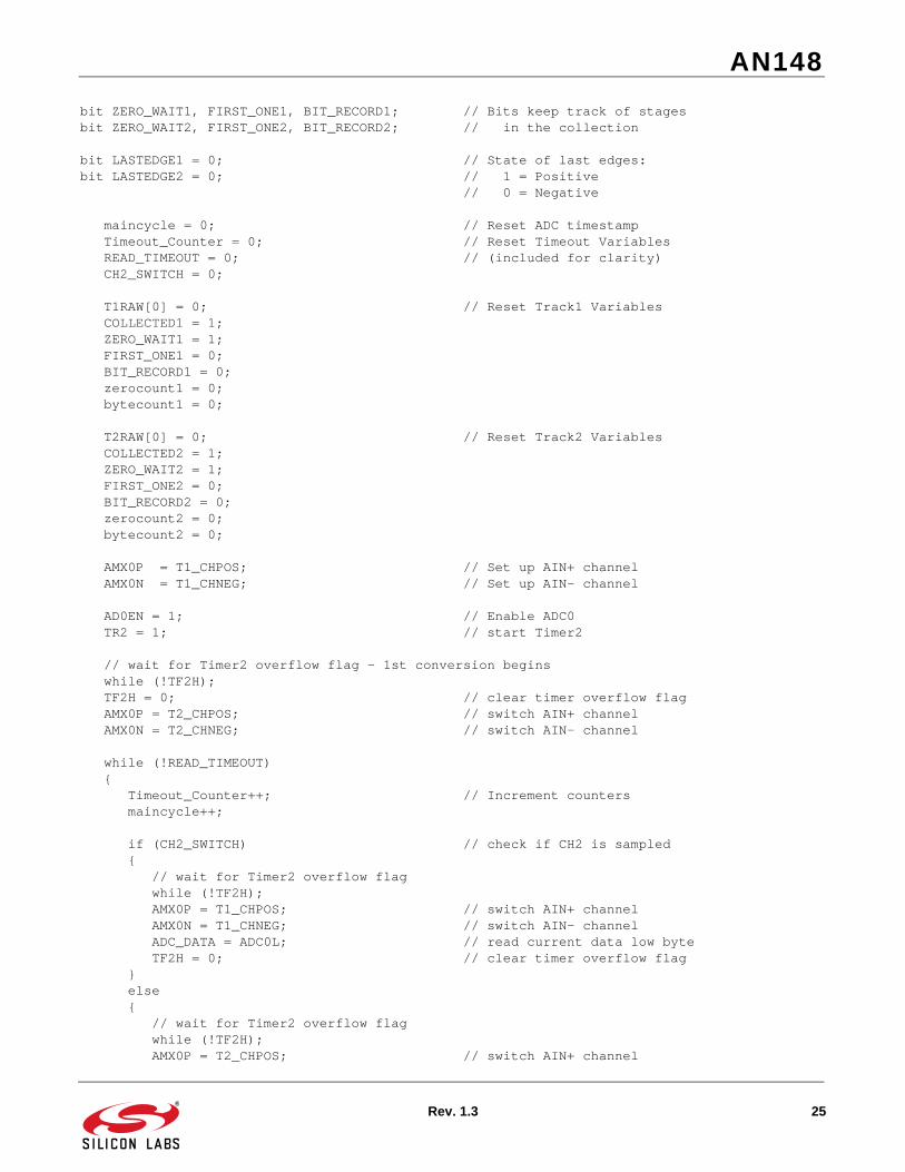
bit ZERO_WAIT1, FIRST_ONE1, BIT_RECORD1; // Bits keep track of stagesbit ZERO_WAIT2, FIRST_ONE2, BIT_RECORD2; // in the collection
bit LASTEDGE1 = 0; // State of last edges:bit LASTEDGE2 = 0; // 1 = Positive // 0 = Negative
maincycle = 0; // Reset ADC timestamp Timeout_Counter = 0; // Reset Timeout Variables READ_TIMEOUT = 0; // (included for clarity) CH2_SWITCH = 0;
T1RAW[0] = 0; // Reset Track1 Variables COLLECTED1 = 1; ZERO_WAIT1 = 1; FIRST_ONE1 = 0; BIT_RECORD1 = 0; zerocount1 = 0; bytecount1 = 0;
T2RAW[0] = 0; // Reset Track2 Variables COLLECTED2 = 1; ZERO_WAIT2 = 1; FIRST_ONE2 = 0; BIT_RECORD2 = 0; zerocount2 = 0; bytecount2 = 0;
AMX0P = T1_CHPOS; // Set up AIN+ channel AMX0N = T1_CHNEG; // Set up AIN- channel
AD0EN = 1; // Enable ADC0 TR2 = 1; // start Timer2
// wait for Timer2 overflow flag - 1st conversion begins while (!TF2H); TF2H = 0; // clear timer overflow flag AMX0P = T2_CHPOS; // switch AIN+ channel AMX0N = T2_CHNEG; // switch AIN- channel
while (!READ_TIMEOUT) { Timeout_Counter++; // Increment counters maincycle++;
if (CH2_SWITCH) // check if CH2 is sampled { // wait for Timer2 overflow flag while (!TF2H); AMX0P = T1_CHPOS; // switch AIN+ channel AMX0N = T1_CHNEG; // switch AIN- channel ADC_DATA = ADC0L; // read current data low byte TF2H = 0; // clear timer overflow flag } else { // wait for Timer2 overflow flag while (!TF2H); AMX0P = T2_CHPOS; // switch AIN+ channel

AN148
26 Rev. 1.3
AMX0N = T2_CHNEG; // switch AIN- channel ADC_DATA = ADC0L; // read current data low byte TF2H = 0; // clear timer overflow flag }
// Perform exponential average runningsum1 = runningsum1 + ADC_DATA - rsum1_div; rsum1_div = runningsum1>>2;
if (!ZERO_WAIT1) // Test to see if still waiting for zeros { // If NOT.. collect data
if (!LASTEDGE1) // Test if last edge was negative { if (runningsum1 > next_peak1) // Test against peak limit { // Establish new local max // and compute min-max // peak timing localmax1 = runningsum1; cyclecount1 += mintime1 - maxtime1; next_peak1 = localmax1 - THRESHOLD1;
if (cyclecount1 <= CP75pct1) // 1/2 or Full cycle? { // **1/2 cycle BIT_RECORD1 = 1; FIRST_ONE1 = 1; } else // **Full cycle { cyclesum1 += cyclecount1; // Update cycle sum cycleindex1++;
if (FIRST_ONE1) // If first ‘1’ is found { Temp_Byte1 = Temp_Byte1 << 1; Temp1_b0 = BIT_RECORD1; // Record a bit bytecount1++; BIT_RECORD1 = 0; // Reset bit value to ‘0’ } cyclecount1 = 0; // Reset cycle counter CLEAR_TIMEOUT = 0; // Keep from timing out } LASTEDGE1 = 1; // Positive edge } else if (runningsum1 < localmin1) // Check against local min { localmin1 = runningsum1; // Update local min // and next peak next_peak1 = localmin1 + THRESHOLD1; mintime1 = maincycle; // Time stamp local min } else // Perform some housekeeping { if (bytecount1 == 8) // Store the current byte { T1RAW[COLLECTED1] = Temp_Byte1; bytecount1 = 0; COLLECTED1++;

AN148
Rev. 1.3 27
} if (cycleindex1 >= 3) // Calculate 75% Value { CP75pct1 = cyclesum1 >> 2; cyclesum1 = 0; cycleindex1 = 0; } } } else // Last edge was positive.. { if (runningsum1 < next_peak1) // Test against peak limit { // Establish new local min // and compute max-min // peak timing localmin1 = runningsum1; cyclecount1 += maxtime1 - mintime1; next_peak1 = localmin1 + THRESHOLD1;
if (cyclecount1 <= CP75pct1) // 1/2 or Full cycle? { // **1/2 cycle BIT_RECORD1 = 1; FIRST_ONE1 = 1; } else // **Full cycle { cyclesum1 += cyclecount1; // Update cycle sum cycleindex1++;
if (FIRST_ONE1) // If first ‘1’ is found { Temp_Byte1 = Temp_Byte1 << 1; Temp1_b0 = BIT_RECORD1; // Record a bit bytecount1++; BIT_RECORD1 = 0; // Reset bit value to ‘0’ } cyclecount1 = 0; // Reset cycle counter CLEAR_TIMEOUT = 0; } LASTEDGE1 = 0; // Negative edge } else if (runningsum1 > localmax1) // Check against local max { localmax1 = runningsum1; // Update local max // and next peak next_peak1 = localmax1 - THRESHOLD1; maxtime1 = maincycle; // Time stamp local max } else // Perform some housekeeping { if (bytecount1 == 8) // Store the current byte { T1RAW[COLLECTED1] = Temp_Byte1; bytecount1 = 0; COLLECTED1++; } if (cycleindex1 >= 3) // Calculate 75% Value {

AN148
28 Rev. 1.3
CP75pct1 = cyclesum1 >> 2; cyclesum1 = 0; cycleindex1 = 0; } } } } // End of data collection code (after Z_LIMIT zeros detected)
else // IF ZERO_WAIT1 == 1, still waiting for Z_LIMIT zeros { CLEAR_TIMEOUT = 0;
if (!LASTEDGE1) // Test if last edge was negative { if (runningsum1 > next_peak1) // Test against peak limit { // Establish new local max // and compute min-max // peak timing localmax1 = runningsum1; cyclecount1 += mintime1 - maxtime1; next_peak1 = localmax1 - THRESHOLD1;
cyclesum1 += cyclecount1; // Update cycle sum cycleindex1++;
// Check for a value that looks periodic if ((cyclecount1 > CP75pct1)&&(cyclecount1 < CP150pct1)) { if (++zerocount1 == Z_LIMIT) // Count up and check { // for Z_LIMIT ZERO_WAIT1 = 0; TK1_RED_LED = 1; TK1_GRN_LED = 1; } } else // Outside of range { zerocount1 = 0; // Reset zero count }
cyclecount1 = 0; // Reset cycle counter LASTEDGE1 = 1; // Positive edge } else if (runningsum1 < localmin1) // Check against local min { localmin1 = runningsum1; // Update local min // and next peak next_peak1 = localmin1 + THRESHOLD1; mintime1 = maincycle; // Time stamp local min } else // Perform some housekeeping { if (cycleindex1 >= 3) // Calculate 75% and 150% { CP150pct1 = cyclesum1 >> 1; CP75pct1 = CP150pct1 >> 1; cyclesum1 = 0; cycleindex1 = 0;

AN148
Rev. 1.3 29
} } } else // Last edge was positive { if (runningsum1 < next_peak1) // Test against peak limit { // Establish new local min // and compute max-min // peak timing localmin1 = runningsum1; cyclecount1 += maxtime1 - mintime1; next_peak1 = localmin1 + THRESHOLD1;
cyclesum1 += cyclecount1; // Update cycle sum cycleindex1++;
// Check for a value that looks periodic if ((cyclecount1 > CP75pct1)&&(cyclecount1 < CP150pct1)) { if (++zerocount1 == Z_LIMIT) // Count up and check { // for Z_LIMIT ZERO_WAIT1 = 0; TK1_RED_LED = 1; TK1_GRN_LED = 1; } } else // Outside of range { zerocount1 = 0; // Reset zero count } cyclecount1 = 0; // Reset cycle counter LASTEDGE1 = 0; // Negative edge } else if (runningsum1 > localmax1) // Check against local max { localmax1 = runningsum1; // Update local max // and next peak next_peak1 = localmax1 - THRESHOLD1; maxtime1 = maincycle; // Time stamp local max } else // Perform some housekeeping { if (cycleindex1 >= 3) // Calculate 75% and 150% { CP150pct1 = cyclesum1 >> 1; CP75pct1 = CP150pct1 >> 1; cyclesum1 = 0; cycleindex1 = 0; } } } } // End of Waiting for Zeroes code (before Z_LIMIT reached)
if (CH2_SWITCH) // Check if CH2 is sampled { // wait for Timer2 overflow flag while (!TF2H);

AN148
30 Rev. 1.3
AMX0P = T1_CHPOS; // switch AIN+ channel AMX0N = T1_CHNEG; // switch AIN- channel ADC_DATA = ADC0L; // read current data low byte TF2H = 0; // clear timer overflow flag
// Perform exponential average runningsum2 = runningsum2 + ADC_DATA - rsum2_div; rsum2_div = runningsum2>>2;
maincycle++;
if (!ZERO_WAIT2) // Test to see if still waiting for zeros { // If NOT.. collect data
if (!LASTEDGE2) // Test if last edge was negative { if (runningsum2 > next_peak2) // Test against peak limit { // Establish new local max // and compute min-max // peak timing localmax2 = runningsum2; cyclecount2 += mintime2 - maxtime2; next_peak2 = localmax2 - THRESHOLD2;
if (cyclecount2 <= CP75pct2) // 1/2 or Full cycle? { // **1/2 cycle BIT_RECORD2 = 1; FIRST_ONE2 = 1; } else // **Full cycle { cyclesum2 += cyclecount2; // Update cycle sum cycleindex2++;
if (FIRST_ONE2) // If first ‘1’ is found { Temp_Byte2 = Temp_Byte2 << 1; Temp2_b0 = BIT_RECORD2; // Record a bit bytecount2++; BIT_RECORD2 = 0; // Reset bit value to ‘0’ } cyclecount2 = 0; // Reset cycle counter } LASTEDGE2 = 1; // Positive edge } else if (runningsum2 < localmin2) // Check against local min { // Update local min localmin2 = runningsum2; // and next peak next_peak2 = localmin2 + THRESHOLD2; mintime2 = maincycle; // Time stamp local min } else // Perform some housekeeping { if (bytecount2 == 8) // Store the current byte { T2RAW[COLLECTED2] = Temp_Byte2; bytecount2 = 0;

AN148
Rev. 1.3 31
COLLECTED2++; } if (cycleindex2 >= 3) // Calculate 75% Value { CP75pct2 = cyclesum2 >> 2; cyclesum2 = 0; cycleindex2 = 0; } } } else // Last edge was positive.. { if (runningsum2 < next_peak2) // Test against peak limit { // Establish new local min // and compute max-min // peak timing localmin2 = runningsum2; cyclecount2 += maxtime2 - mintime2; next_peak2 = localmin2 + THRESHOLD2;
if (cyclecount2 <= CP75pct2) // 1/2 or Full cycle? { // **1/2 cycle BIT_RECORD2 = 1; FIRST_ONE2 = 1; } else // **Full cycle { cyclesum2 += cyclecount2; // Update cycle sum cycleindex2++;
if (FIRST_ONE2) // If first ‘1’ is found { Temp_Byte2 = Temp_Byte2 << 1; Temp2_b0 = BIT_RECORD2; // Record a bit bytecount2++; BIT_RECORD2 = 0; // Reset bit value to ‘0’ } cyclecount2 = 0; // Reset cycle counter } LASTEDGE2 = 0; // Negative edge } else if (runningsum2 > localmax2) // Check against local max { // Update local max localmax2 = runningsum2; // and next peak next_peak2 = localmax2 - THRESHOLD2; maxtime2 = maincycle; // Time stamp local max
} else // Perform some housekeeping { if (bytecount2 == 8) // Store the current byte { T2RAW[COLLECTED2] = Temp_Byte2; bytecount2 = 0; COLLECTED2++; } if (cycleindex2 >= 3) // Calculate 75% Value
AN148
32 Rev. 1.3
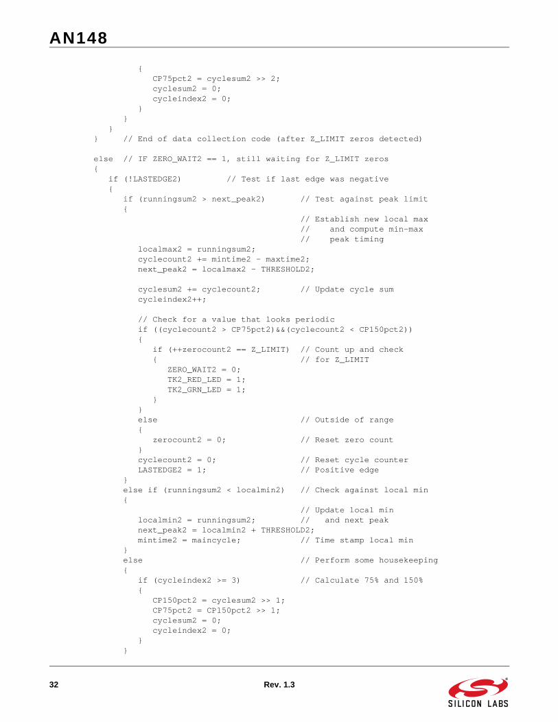
{ CP75pct2 = cyclesum2 >> 2; cyclesum2 = 0; cycleindex2 = 0; } } } } // End of data collection code (after Z_LIMIT zeros detected)
else // IF ZERO_WAIT2 == 1, still waiting for Z_LIMIT zeros { if (!LASTEDGE2) // Test if last edge was negative { if (runningsum2 > next_peak2) // Test against peak limit { // Establish new local max // and compute min-max // peak timing localmax2 = runningsum2; cyclecount2 += mintime2 - maxtime2; next_peak2 = localmax2 - THRESHOLD2;
cyclesum2 += cyclecount2; // Update cycle sum cycleindex2++;
// Check for a value that looks periodic if ((cyclecount2 > CP75pct2)&&(cyclecount2 < CP150pct2)) { if (++zerocount2 == Z_LIMIT) // Count up and check { // for Z_LIMIT ZERO_WAIT2 = 0; TK2_RED_LED = 1; TK2_GRN_LED = 1; } } else // Outside of range { zerocount2 = 0; // Reset zero count } cyclecount2 = 0; // Reset cycle counter LASTEDGE2 = 1; // Positive edge } else if (runningsum2 < localmin2) // Check against local min { // Update local min localmin2 = runningsum2; // and next peak next_peak2 = localmin2 + THRESHOLD2; mintime2 = maincycle; // Time stamp local min } else // Perform some housekeeping { if (cycleindex2 >= 3) // Calculate 75% and 150% { CP150pct2 = cyclesum2 >> 1; CP75pct2 = CP150pct2 >> 1; cyclesum2 = 0; cycleindex2 = 0; } }

AN148
Rev. 1.3 33
} else // Last edge was positive { if (runningsum2 < next_peak2) // Test against peak limit { // Establish new local min // and compute max-min // peak timing localmin2 = runningsum2; cyclecount2 += maxtime2 - mintime2; next_peak2 = localmin2 + THRESHOLD2;
cyclesum2 += cyclecount2; // Update cycle sum cycleindex2++;
// Check for a value that looks periodic if ((cyclecount2 > CP75pct2)&&(cyclecount2 < CP150pct2)) { if (++zerocount2 == Z_LIMIT) // Count up and check { // for Z_LIMIT ZERO_WAIT2 = 0; TK2_RED_LED = 1; TK2_GRN_LED = 1; } } else // Outside of range { zerocount2 = 0; // Reset zero count } cyclecount2 = 0; // Reset cycle counter LASTEDGE2 = 0; // Negative edge } else if (runningsum2 > localmax2) // Check against local max { // Update local max localmax2 = runningsum2; // and next peak next_peak2 = localmax2 - THRESHOLD2; maxtime2 = maincycle; // Time stamp local max } else // Perform some housekeeping { if (cycleindex2 >= 3) // Calculate 75% and 150% { CP150pct2 = cyclesum2 >> 1; CP75pct2 = CP150pct2 >> 1; cyclesum2 = 0; cycleindex2 = 0; } } } } // End of Waiting for Zeroes code (before Z_LIMIT reached)
} // End IF CH2_SWITCH
} // End While (!READ_TIMEOUT)
// Finish off last bytes with zeros.. while (bytecount1 < 8) {

AN148
34 Rev. 1.3
Temp_Byte1 = Temp_Byte1 << 1; Temp1_b0 = 0; // record a zero bytecount1++; } T1RAW[COLLECTED1] = Temp_Byte1;
while (bytecount2 < 8) { Temp_Byte2 = Temp_Byte2 << 1; Temp2_b0 = 0; // record a zero bytecount2++; } T2RAW[COLLECTED2] = Temp_Byte2;
return (1);}
//-----------------------------------------------------------------------------// TrackErrorCheck//-----------------------------------------------------------------------------//// This routine checks the decoded track data for Start Sentinel, End Sentinel,// Parity, and LRC errors.//
char TrackErrorCheck (unsigned char maxindex, unsigned char StartSen, unsigned char EndSen, unsigned char CharBits){unsigned char idata ASCII_Index, ASCII_Mask;unsigned char idata ASCII_Data, PC_count, Read_LRC = 0, Calc_LRC = 0;char idata errorcode = 0;bit ES_Found = 0, ParityCheck = 0;
ASCII_Mask = 0x7F >> (8 - CharBits); // Mask used to separate data info
if (ASCII_array[0] != StartSen) // Check for SS at start of array { errorcode |= 0x81; // ERROR - SS is not 1st character }
// Loop through ASCII_array and check each byte for errors for (ASCII_Index = 0; ASCII_Index <= maxindex; ASCII_Index++) { ASCII_Data = ASCII_array[ASCII_Index]; if (!ES_Found) // If ES not found yet { // LRC Check - XOR’s data from all bytes (except the LRC) Calc_LRC ^= (ASCII_Data & ASCII_Mask);
if (ASCII_Data == EndSen) // If this is the End Sentinel, { // treat the next character as // the LRC, and signal that // the ES has been found Read_LRC = (ASCII_array[ASCII_Index+1] & ASCII_Mask); maxindex = ASCII_Index+1; ES_Found = 1; } }

AN148
Rev. 1.3 35
// Parity Check - checks #1’s against Parity bit for ODD parity. ParityCheck = 0; // Reset parity check variable for (PC_count = 0; PC_count < CharBits; PC_count++) { ParityCheck ^= (ASCII_Data & 0x01); ASCII_Data = ASCII_Data >> 1; } if (ParityCheck == (ASCII_Data & 0x01)) { ASCII_array[ASCII_Index] |= 0x80; // Mark this byte for ID later errorcode |= 0x88; // ERROR - Parity error } }
// Check that End Sentinel was found in captured data if (!ES_Found) { errorcode |=0x82; // ERROR - End Sentinel never found } // If ES was found... else if (Calc_LRC != (Read_LRC & ASCII_Mask)) { errorcode |= 0x84; // LRC error
// Parity Check for LRC - checks #1’s against Parity bit for ODD parity. ParityCheck = 0; // Reset parity check variable for (PC_count = 0; PC_count < CharBits; PC_count++) { ParityCheck ^= (Read_LRC & 0x01); Read_LRC = Read_LRC >> 1; } if (ParityCheck == (Read_LRC & 0x01)) { ASCII_array[maxindex] |= 0x80; // Mark LRC byte for ID later errorcode |= 0x88; // ERROR - Parity error } }
// If no errors were detected, return the number of bytes found. // Otherwise, return the error code. if (errorcode == 0) { return ASCII_Index; } else { return errorcode; }
}
//-----------------------------------------------------------------------------// DecodeTrackForward//-----------------------------------------------------------------------------//// This routine is used to decode a track into characters, assuming it was// recorded in the forward direction into the array.//

AN148
36 Rev. 1.3
char DecodeTrackForward (unsigned char maxindex, unsigned char Byte_Offset, unsigned char Bit_Offset, unsigned char *TrackRAW, unsigned char CharBits){unsigned char idata Track_Index = 0;char idata ASCII_Index = 0, ASCII_Mask;unsigned char idata Track_Data, ASCII_Data;unsigned char idata Track_bit, ASCII_bit;
// Reset temporary variables ASCII_bit = 0x01; ASCII_Data = 0x00;
// Generate a bit comparison value for sorting through ASCII bytes ASCII_Mask = 0x01 << (CharBits-1);
// Begin at the specified offset, and proceed until the end of the track for (Track_Index = Byte_Offset; Track_Index <= maxindex; Track_Index++) { // Grab a byte of raw data Track_Data = TrackRAW[Track_Index];
// Unpack raw data byte into character(s) for (Track_bit = Bit_Offset; Track_bit != 0x00; Track_bit = Track_bit>>1) { if (Track_bit & Track_Data) { ASCII_Data |= ASCII_bit; } else { ASCII_Data &= ~ASCII_bit; } if (ASCII_bit != ASCII_Mask) { ASCII_bit = ASCII_bit << 1; } else { ASCII_bit = 0x01; ASCII_array[ASCII_Index] = ASCII_Data;
if ((ASCII_Data == 0x00)||(ASCII_Index == 126)) { Track_Index = maxindex; // end translation }
ASCII_Index++; } } }
// Return the number of characters unpacked return (ASCII_Index);
}
//-----------------------------------------------------------------------------// DecodeTrackBackward

AN148
Rev. 1.3 37
//-----------------------------------------------------------------------------//// This routine is used to decode a track into characters, assuming it was// recorded in the backward direction into the array.//char DecodeTrackBackward (unsigned char Byte_Offset, unsigned char Bit_Offset, unsigned char *TrackRAW, unsigned char CharBits){unsigned char idata Track_Index;char idata ASCII_Index = 0, ASCII_Mask;unsigned char idata Track_Data, ASCII_Data;unsigned char idata ASCII_bit;
// Reset temporary variables ASCII_bit = 0x01; ASCII_Data = 0x00;
// Generate a bit comparison value for sorting through ASCII bytes ASCII_Mask = 0x01 << (CharBits-1);
// Begin at the specified offset, and proceed until the beginning for (Track_Index = Byte_Offset; Track_Index != 0x00; Track_Index--) { // Grab a byte of raw data Track_Data = TrackRAW[Track_Index];
// Unpack raw data byte into character(s) while (Bit_Offset != 0x00) { if (Bit_Offset & Track_Data) { ASCII_Data |= ASCII_bit; } else { ASCII_Data &= ~ASCII_bit; } if (ASCII_bit != ASCII_Mask) { ASCII_bit = ASCII_bit << 1; } else { ASCII_bit = 0x01; ASCII_array[ASCII_Index] = ASCII_Data; ASCII_Data = 0; ASCII_Index++; } Bit_Offset = Bit_Offset << 1; } Bit_Offset = 0x01; }
// Finish off last byte with trailing zeros ASCII_Mask = ASCII_Mask << 1; while (ASCII_bit != ASCII_Mask) { ASCII_Data &= ~ASCII_bit;

AN148
38 Rev. 1.3
ASCII_bit = ASCII_bit << 1; } ASCII_array[ASCII_Index] = ASCII_Data;
// Return the number of characters unpacked return (ASCII_Index);
}
//-----------------------------------------------------------------------------// GetDirection//-----------------------------------------------------------------------------//// This routine determines which direction data was collected from the magnetic// stripe and calls the appropriate decoding routine.//
char GetDirection (unsigned char maxindex, unsigned char StartSen, unsigned char EndSen, unsigned char *TrackRAW, unsigned char CharBits){
unsigned char idata FW_Byte_Off, FW_Bit_Off, RV_Byte_Off, RV_Bit_Off;unsigned char idata Read_Char, Bit_Count, Temp_Char, Temp_Bit, Temp_Mask;char idata MAX_Decoded;bit FW_StartSen, RV_StartSen, Direction_Found = 0, Abort_Direction = 0;
// Initialize Index Pointers FW_Byte_Off = 1; FW_Bit_Off = 0x80; RV_Byte_Off = maxindex; RV_Bit_Off = 0x01;
while ((Direction_Found == 0)&&(Abort_Direction == 0)) { // Read a byte at FW pointer Read_Char = TrackRAW[FW_Byte_Off];
// Find the next ‘1’ Forward while ((FW_Byte_Off != RV_Byte_Off)&&((Read_Char & FW_Bit_Off) == 0)) { FW_Bit_Off = FW_Bit_Off >> 1; if (FW_Bit_Off == 00) { FW_Bit_Off = 0x80; FW_Byte_Off++; Read_Char = TrackRAW[FW_Byte_Off]; } }
if (FW_Byte_Off == RV_Byte_Off) { Abort_Direction = 1; }
Temp_Bit = 0x02; Temp_Char = 0x01; Temp_Mask = FW_Bit_Off;

AN148
Rev. 1.3 39
for (Bit_Count = 1; Bit_Count < CharBits; Bit_Count++) { Temp_Mask = Temp_Mask >> 1; if (Temp_Mask == 0x00) { Temp_Mask = 0x80; Read_Char = TrackRAW[FW_Byte_Off+1]; } if (Read_Char & Temp_Mask) { Temp_Char |= Temp_Bit; } else { Temp_Char &= ~Temp_Bit; } Temp_Bit = Temp_Bit << 1; }
// Check character against Start Sentinel if (Temp_Char == StartSen) { FW_StartSen = 1; } else { FW_StartSen = 0; }
// Read a byte at RV pointer Read_Char = TrackRAW[RV_Byte_Off];
// Find the next ‘1’ Reverse while ((FW_Byte_Off != RV_Byte_Off)&&((Read_Char & RV_Bit_Off) == 0)) { RV_Bit_Off = RV_Bit_Off << 1; if (RV_Bit_Off == 00) { RV_Bit_Off = 0x01; RV_Byte_Off--; Read_Char = TrackRAW[RV_Byte_Off]; } }
if (FW_Byte_Off == RV_Byte_Off) { Abort_Direction = 1; }
Temp_Bit = 0x02; Temp_Char = 0x01; Temp_Mask = RV_Bit_Off;
for (Bit_Count = 1; Bit_Count < CharBits; Bit_Count++) { Temp_Mask = Temp_Mask << 1; if (Temp_Mask == 0x00) {

AN148
40 Rev. 1.3
Temp_Mask = 0x01; Read_Char = TrackRAW[RV_Byte_Off-1]; } if (Read_Char & Temp_Mask) { Temp_Char |= Temp_Bit; } else { Temp_Char &= ~Temp_Bit; } Temp_Bit = Temp_Bit << 1; }
// Check character against Start Sentinel if (Temp_Char == StartSen) { RV_StartSen = 1; } else { RV_StartSen = 0; }
if (FW_StartSen ^ RV_StartSen) { Direction_Found = 1; } else if (FW_StartSen && RV_StartSen) { //*** Check for ES Backwards in front Temp_Bit = 0x80; Temp_Char = 0x00; Temp_Mask = FW_Bit_Off;
MAX_Decoded = FW_Byte_Off; // MAX_Decoded used as temporary storage if ((Temp_Mask >> CharBits) != 0x00) { Temp_Mask = Temp_Mask >> CharBits; } else { FW_Byte_Off++; Temp_Mask = Temp_Mask << (8 - CharBits); }
Read_Char = TrackRAW[FW_Byte_Off]; for (Bit_Count = 0; Bit_Count < CharBits; Bit_Count++) { if (Read_Char & Temp_Mask) { Temp_Char |= Temp_Bit; } else { Temp_Char &= ~Temp_Bit; } Temp_Bit = Temp_Bit >> 1;

AN148
Rev. 1.3 41
Temp_Mask = Temp_Mask >> 1; if (Temp_Mask == 0x00) { Temp_Mask = 0x80; Read_Char = TrackRAW[FW_Byte_Off+1]; } } FW_Byte_Off = MAX_Decoded; // Restore FW_Byte_Off
Temp_Char = Temp_Char >> (8 - CharBits); // Check character against End Sentinel // If found here, track is reverse. if (Temp_Char == EndSen) { FW_StartSen = 0; } //otherwise, it is forward else { RV_StartSen = 0; }
Direction_Found = 1; } else if (!Abort_Direction) { FW_Bit_Off = FW_Bit_Off >> 1; if (FW_Bit_Off == 00) { FW_Bit_Off = 0x80; FW_Byte_Off++; } RV_Bit_Off = RV_Bit_Off << 1; if (RV_Bit_Off == 00) { RV_Bit_Off = 0x01; RV_Byte_Off--; }
if (FW_Byte_Off >= RV_Byte_Off) { Abort_Direction = 1; } }
} // End while((Direction_Found == 0)&&(Abort_Direction == 0))
if ((Direction_Found)&&(!Abort_Direction)) { if (FW_StartSen) { MAX_Decoded = DecodeTrackForward(maxindex, FW_Byte_Off, FW_Bit_Off, TrackRAW, CharBits); } else if (RV_StartSen) { MAX_Decoded = DecodeTrackBackward(RV_Byte_Off, RV_Bit_Off, TrackRAW, CharBits); }

AN148
42 Rev. 1.3
} else { MAX_Decoded = 0x81; // Could not find Start Sentinel }
return (MAX_Decoded);
}
//-----------------------------------------------------------------------------// UART_CharOut//-----------------------------------------------------------------------------//// This routine sends a single character to the UART. It is used in lieu of// printf() to reduce overall code size.//
void UART_CharOut (unsigned char c){ if (c == ‘\n’) { while (!TI0); TI0 = 0; SBUF0 = 0x0d; /* output CR */ } while (!TI0); TI0 = 0; SBUF0 = c;}
//-----------------------------------------------------------------------------// UART_StringOut//-----------------------------------------------------------------------------//// This routine calls the UART_CharOut repeatedly to send a string value to the// UART. It is used in lieu of printf() to reduce overall code size.//
void UART_StringOut (unsigned char *c){ while (*c != 0x00) { UART_CharOut(*c); c++; }}
#if DEBUG//-----------------------------------------------------------------------------// UART_HexOut//-----------------------------------------------------------------------------//// This routine sends the hexadecimal value of a character to the UART as ASCII// text. Only used when DEBUG = 1.//void UART_HexOut (unsigned char c){

AN148
Rev. 1.3 43
while (!TI0); TI0 = 0; if ((c & 0xF0) < 0xA0) SBUF0 = ((c >> 4) & 0x0F) + 0x30; else SBUF0 = ((c >> 4) & 0x0F) + 0x37;
while (!TI0); TI0 = 0; if ((c & 0x0F) < 0x0A) SBUF0 = (c & 0x0F) + 0x30; else SBUF0 = (c & 0x0F) + 0x37;
}#endif // END #if DEBUG

AN148
44 Rev. 1.3
APPENDIX F—FIRMWARE LISTING FOR 3-CHANNEL EXAMPLE
//-----------------------------------------------------------------------------// MagStripeReaderF330_3CH.c//-----------------------------------------------------------------------------// Copyright 2004 Silicon Laboratories//// AUTH: BD// DATE: 3 MAR 04// VER: 2.0//// This program reads the magnetic stripe from a card written in the standard// ISO 3-channel format using F2F encoding. Read data is output to the UART// after being decoded.//// Target: C8051F33x// Tool chain: KEIL C51 7.06 / KEIL EVAL C51//
//-----------------------------------------------------------------------------// Includes//-----------------------------------------------------------------------------
#include <c8051f330.h> // SFR declarations for C8051F330
//-----------------------------------------------------------------------------// 16-bit SFR Definitions for ‘F33x//-----------------------------------------------------------------------------sfr16 TMR2RL = 0xca; // Timer2 reload valuesfr16 TMR2 = 0xcc; // Timer2 counter
//-----------------------------------------------------------------------------// Conditional Compilation CONSTANTS//-----------------------------------------------------------------------------
#define DEBUG 0 // Set to ‘1’ for extra information#define T3_5BIT 1 // Set to ‘1’ for T3 5-bit encoding // Set to ‘0’ for T3 7-bit encoding
// **NOTE** The Track 3 encoding scheme is different for different card types// The ISO-4909 standard uses 5-bit Track 3 encoding// Many cards now use 7-bit encoding for Track 3
//-----------------------------------------------------------------------------// Global CONSTANTS//-----------------------------------------------------------------------------
#define SYSCLK 24500000 // SYSCLK frequency in Hz#define BAUDRATE 115200 // Baud rate of UART in bps#define SAMPLE_RATE 200000 // Sample rate of ADC
#define T1_SS 0x45 // Start Sentinel + parity#define T1_ES 0x1F // End Sentinel + parity#define T1_BITS 7 // data + parity bit#define T1_CHPOS 0x08 // Positive ADC Mux channel

AN148
Rev. 1.3 45
#define T1_CHNEG 0x09 // Negative ADC Mux channel
#define T2_SS 0x0B // Start Sentinel + parity#define T2_ES 0x1F // End Sentinel + parity#define T2_BITS 5 // data + parity bit#define T2_CHPOS 0x0A // Positive ADC Mux channel#define T2_CHNEG 0x0B // Negative ADC Mux channel
#if T3_5BIT // Use 5-bit encoding on Track 3#define T3_SS 0x0B // Start Sentinel + parity#define T3_ES 0x1F // End Sentinel + parity#define T3_BITS 5 // data + parity bit#endif
#if !T3_5BIT // Use 7-bit encoding on Track 3#define T3_SS 0x45 // Start Sentinel + parity#define T3_ES 0x1F // End Sentinel + parity#define T3_BITS 7 // data + parity bit#endif
#define T3_CHPOS 0x0C // Positive ADC Mux channel#define T3_CHNEG 0x0D // Negative ADC Mux channel
#define THRESHOLD1 7 // Noise threshold limits#define THRESHOLD2 7#define THRESHOLD3 7
#define Z_LIMIT 3 // Number of Zeros before recording
sbit TK1_GRN_LED = P0^2; // GREEN LED TK1sbit TK1_RED_LED = P0^3; // RED LED TK1
sbit TK2_GRN_LED = P0^6; // GREEN LED TK2sbit TK2_RED_LED = P0^7; // RED LED TK2
sbit TK3_GRN_LED = P1^6; // GREEN LED TK3sbit TK3_RED_LED = P1^7; // RED LED TK3
//-----------------------------------------------------------------------------// Global VARIABLES//-----------------------------------------------------------------------------
unsigned char xdata T1RAW[100], T2RAW[100], // Track 1 and 2 Raw Data T3RAW[100]; // Track 3 Raw Dataunsigned char xdata ASCII_array[128]; // Decoded Informationunsigned char COLLECTED1 = 1, COLLECTED2 = 1, // Raw data indices COLLECTED3 = 1;
unsigned int bdata Timeout_Counter; // Bit-Addressable Timeout countersbit CLEAR_TIMEOUT = Timeout_Counter ^ 4; // Used to keep from timing outsbit READ_TIMEOUT = Timeout_Counter ^ 5; // Indicates when read is finishedsbit CH2_SWITCH = Timeout_Counter ^ 8; // LSB of counter: // If ‘1’, CH2 is sampled // If ‘0’, CH2 is skipped
unsigned char bdata Temp_Byte1; // Bit-Addressable Temporary Storagesbit Temp1_b0 = Temp_Byte1 ^ 0; // LSB of Temp_Byte1

AN148
46 Rev. 1.3
unsigned char bdata Temp_Byte2; // Bit-Addressable Temporary Storagesbit Temp2_b0 = Temp_Byte2 ^ 0; // LSB of Temp_Byte2
unsigned char bdata Temp_Byte3; // Bit-Addressable Temporary Storagesbit Temp3_b0 = Temp_Byte3 ^ 0; // LSB of Temp_Byte3
//-----------------------------------------------------------------------------// Function PROTOTYPES//-----------------------------------------------------------------------------
void SYSCLK_Init (void);void ADC0_Init (void);void UART0_Init (void);void PORT_Init (void);void Timer2_Init (int);
unsigned char Swipe_Card(void);
char GetDirection (unsigned char maxindex, unsigned char StartSen, unsigned char EndSen, unsigned char *TrackRAW, unsigned char CharBits);char DecodeTrackForward (unsigned char maxindex, unsigned char Byte_Offset, unsigned char Bit_Offset, unsigned char *TrackRAW, unsigned char CharBits);
char DecodeTrackBackward (unsigned char Byte_Offset, unsigned char Bit_Offset, unsigned char *TrackRAW, unsigned char CharBits);
char TrackErrorCheck (unsigned char maxindex, unsigned char StartSen, unsigned char EndSen, unsigned char CharBits);
void UART_CharOut (unsigned char c);void UART_StringOut (unsigned char *c);void UART_HexOut (unsigned char c);
//-----------------------------------------------------------------------------// MAIN Routine//-----------------------------------------------------------------------------
void main (void) {
unsigned char idata Return_Code;unsigned char idata colCount;bit ERRT1, ERRT2, ERRT3; // Track 1, 2, 3 Error Flags
// Disable Watchdog timer PCA0MD &= ~0x40; // WDTE = 0 (clear watchdog timer // enable) PORT_Init(); // Initialize Port I/O SYSCLK_Init (); // Initialize Oscillator
ADC0_Init (); // Init ADC0 Timer2_Init(SYSCLK/SAMPLE_RATE); // Init Timer 2 w/ ADC sample rate UART0_Init();
while (1) {

AN148
Rev. 1.3 47
#if DEBUG UART_StringOut(“\nTesting”);#endif // END #if DEBUG
UART_StringOut(“\n”);
Swipe_Card();
// If DEBUG is ‘1’, use verbose mode for output#if DEBUG
// Find direction of track1, and decode to character array Return_Code = GetDirection(COLLECTED1, T1_SS, T1_ES, T1RAW, T1_BITS);
if ((Return_Code & 0x80) == 0) // If no error was detected { // Check character array for SS, ES, Parity, and LRC Return_Code = TrackErrorCheck(Return_Code, T1_SS, T1_ES, T1_BITS); }
if (Return_Code & 0x80) // If an error was detected { ERRT1 = 1; UART_StringOut(“\nErrors: \n”); // List the errors detected
if (Return_Code & 0x01) { UART_StringOut(“\tStart Sentinel not found\n”); } if (Return_Code & 0x02) { UART_StringOut(“\tEnd Sentinel not found\n”); } if (Return_Code & 0x04) { UART_StringOut(“\tLRC incorrect\n”); } if (Return_Code & 0x08) { UART_StringOut(“\tParity error(s)\n”); }
UART_StringOut(“\nDATA CH1:\n”); for (colCount = 0; colCount < 128; colCount++) { UART_CharOut(0x20 + (ASCII_array[colCount]&0x3F)); UART_CharOut(0x30); } UART_CharOut(‘\n’); UART_StringOut(“END DATA CH1\n”); } else // No errors, print T1 data { ERRT1 = 0; UART_StringOut(“\nDATA CH1:\n”);
for (colCount = 0; colCount < Return_Code; colCount++) { UART_CharOut(0x20 + (ASCII_array[colCount]&0x3F));

AN148
48 Rev. 1.3
ASCII_array[colCount] = 0x30; } UART_CharOut(‘\n’); UART_StringOut(“END DATA CH1\n”); }
// Print the RAW data for Track 1 UART_StringOut(“\nRAW COLLECTION CH1:\n0x”);
for (colCount = 0; colCount < COLLECTED1; colCount++) { UART_HexOut (T1RAW[colCount]); }
UART_CharOut(‘\n’); UART_StringOut(“END RAW CH1\n”);
// Find direction of track2, and decode to character array Return_Code = GetDirection(COLLECTED2, T2_SS, T2_ES, T2RAW, T2_BITS);
if ((Return_Code & 0x80) == 0) // If no error was detected { // Check character array for SS, ES, Parity, and LRC Return_Code = TrackErrorCheck(Return_Code, T2_SS, T2_ES, T2_BITS); }
if (Return_Code & 0x80) // If an error was detected { ERRT2 = 1; UART_StringOut(“\nErrors: \n”); // List the errors detected
if (Return_Code & 0x01) { UART_StringOut(“\tStart Sentinel not found\n”); } if (Return_Code & 0x02) { UART_StringOut(“\tEnd Sentinel not found\n”); } if (Return_Code & 0x04) { UART_StringOut(“\tLRC incorrect\n”); } if (Return_Code & 0x08) { UART_StringOut(“\tParity error(s)\n”); }
UART_StringOut(“\nDATA CH2:\n”); for (colCount = 0; colCount < 128; colCount++) { UART_CharOut(0x30 + (ASCII_array[colCount]&0x0F)); ASCII_array[colCount] = 0x30; } UART_CharOut(‘\n’); UART_StringOut(“END DATA CH2\n”); } else // No errors, print T2 data {

AN148
Rev. 1.3 49
ERRT2 = 0; UART_StringOut(“\nDATA CH2:\n”);
for (colCount = 0; colCount < Return_Code; colCount++) { UART_CharOut(0x30 + (ASCII_array[colCount]&0x0F)); ASCII_array[colCount] = 0x30; } UART_CharOut(‘\n’); UART_StringOut(“END DATA CH2\n”); }
// Print the RAW data for Track 2 UART_StringOut(“\nRAW COLLECTION CH2:\n0x”);
for (colCount = 0; colCount < COLLECTED2; colCount++) { UART_HexOut (T2RAW[colCount]); }
UART_CharOut(‘\n’); UART_StringOut(“END RAW CH2\n”);
// Find direction of track3, and decode to character array Return_Code = GetDirection(COLLECTED3, T3_SS, T3_ES, T3RAW, T3_BITS);
if ((Return_Code & 0x80) == 0) // If no error was detected { // Check character array for SS, ES, Parity, and LRC Return_Code = TrackErrorCheck(Return_Code, T3_SS, T3_ES, T3_BITS); }
if (Return_Code & 0x80) // If an error was detected { ERRT3 = 1; UART_StringOut(“\nErrors: “); // List the errors detected UART_CharOut(‘\n’);
if (Return_Code & 0x01) { UART_StringOut(“\tStart Sentinel not found\n”); } if (Return_Code & 0x02) { UART_StringOut(“\tEnd Sentinel not found\n”); } if (Return_Code & 0x04) { UART_StringOut(“\tLRC incorrect\n”); } if (Return_Code & 0x08) { UART_StringOut(“\tParity error(s)\n”); }
UART_StringOut(“\nDATA CH3:\n”); for (colCount = 0; colCount < 128; colCount++) { UART_CharOut(0x30 + (ASCII_array[colCount]&0x0F));

AN148
50 Rev. 1.3
ASCII_array[colCount] = 0x30; } UART_CharOut(‘\n’); UART_StringOut(“END DATA CH3\n”); } else // No errors, print T3 data { ERRT3 = 0; UART_StringOut(“\nDATA CH3:\n”);
for (colCount = 0; colCount < Return_Code; colCount++) { UART_CharOut(0x30 + (ASCII_array[colCount]&0x0F)); ASCII_array[colCount] = 0x30; } UART_CharOut(‘\n’); UART_StringOut(“END DATA CH3\n”); }
// Print the RAW data for Track 3 UART_StringOut(“\nRAW COLLECTION CH3:\n0x”);
for (colCount = 0; colCount < COLLECTED3; colCount++) { UART_HexOut (T3RAW[colCount]); }
UART_CharOut(‘\n’); UART_StringOut(“END RAW CH3\n”);
// Signal Error / OK with LEDs if (!ERRT1) { TK1_RED_LED = 0; TK1_GRN_LED = 1; } else { TK1_RED_LED = 1; TK1_GRN_LED = 0; } // Signal Error / OK with LEDs if (!ERRT2) { TK2_RED_LED = 0; TK2_GRN_LED = 1; } else { TK2_RED_LED = 1; TK2_GRN_LED = 0; }
// Signal Error / OK with LEDs if (!ERRT3) { TK3_RED_LED = 0;

AN148
Rev. 1.3 51
TK3_GRN_LED = 1; } else { TK3_RED_LED = 1; TK3_GRN_LED = 0; }
#endif // END #if DEBUG
// If DEBUG is ‘0’, only output valid track info#if !DEBUG
// Find direction of track1, and decode to character array Return_Code = GetDirection(COLLECTED1, T1_SS, T1_ES, T1RAW, T1_BITS);
if ((Return_Code & 0x80) == 0) // If no error was detected { // Check character array for SS, ES, Parity, and LRC Return_Code = TrackErrorCheck(Return_Code, T1_SS, T1_ES, T1_BITS); }
if (Return_Code & 0x80) // If an error was detected { // set the error bit ERRT1 = 1; } else // Otherwise print Track 1 { ERRT1 = 0; for (colCount = 0; colCount < Return_Code; colCount++) { UART_CharOut(0x20 + (ASCII_array[colCount]&0x3F)); ASCII_array[colCount] = 0x30; } UART_CharOut(‘\n’); }
// Find direction of track2, and decode to character array Return_Code = GetDirection(COLLECTED2, T2_SS, T2_ES, T2RAW, T2_BITS);
if ((Return_Code & 0x80) == 0) // If no error was detected { // Check character array for SS, ES, Parity, and LRC Return_Code = TrackErrorCheck(Return_Code, T2_SS, T2_ES, T2_BITS); }
if (Return_Code & 0x80) // If an error was detected { // set the error bit ERRT2 = 1; } else // Otherwise print Track 2 { ERRT2 = 0; for (colCount = 0; colCount < Return_Code; colCount++) { UART_CharOut(0x30 + (ASCII_array[colCount]&0x0F)); ASCII_array[colCount] = 0x30; }

AN148
52 Rev. 1.3
UART_CharOut(‘\n’); }
// Find direction of track3, and decode to character array Return_Code = GetDirection(COLLECTED3, T3_SS, T3_ES, T3RAW, T3_BITS);
if ((Return_Code & 0x80) == 0) // If no error was detected { // Check character array for SS, ES, Parity, and LRC Return_Code = TrackErrorCheck(Return_Code, T3_SS, T3_ES, T3_BITS); }
if (Return_Code & 0x80) // If an error was detected { // set the error bit ERRT3 = 1; } else // Otherwise print Track 3 { ERRT3 = 0; for (colCount = 0; colCount < Return_Code; colCount++) { UART_CharOut(0x30 + (ASCII_array[colCount]&0x0F)); ASCII_array[colCount] = 0x30; } UART_CharOut(‘\n’); }
// Signal Error / OK with LEDs if (!ERRT1) { TK1_RED_LED = 0; TK1_GRN_LED = 1; } else { TK1_RED_LED = 1; TK1_GRN_LED = 0; } // Signal Error / OK with LEDs if (!ERRT2) { TK2_RED_LED = 0; TK2_GRN_LED = 1; } else { TK2_RED_LED = 1; TK2_GRN_LED = 0; }
// Signal Error / OK with LEDs if (!ERRT3) { TK3_RED_LED = 0; TK3_GRN_LED = 1; } else {

AN148
Rev. 1.3 53
TK3_RED_LED = 1; TK3_GRN_LED = 0; }#endif // END #if !DEBUG
} // END while(1)} // END main()
//-----------------------------------------------------------------------------// Initialization Subroutines//-----------------------------------------------------------------------------
//-----------------------------------------------------------------------------// PORT_Init//-----------------------------------------------------------------------------//// Configure the Crossbar and GPIO ports.//// P0.0 - VREF Input (analog, skipped)// P0.4 - UART TX (push-pull)// P0.5 - UART RX (open drain)// P1.0 - Channel 1+ (analog, skipped)// P1.1 - Channel 1- (analog, skipped)// P1.2 - Channel 2+ (analog, skipped)// P1.3 - Channel 2- (analog, skipped)// P1.4 - Channel 3+ (analog, skipped)// P1.5 - Channel 3- (analog, skipped)// P1.6 - Green LED (push-pull, skipped)// P1.7 - Red LED (push-pull, skipped)//
void PORT_Init (void){ P0MDOUT |= 0xDC; // enable TX and LEDs as push-pull out
P0MDIN &= ~0x01; // VREF analog in P1MDIN &= ~0x3F; // Enable P1.0 through 1.5 as analog in P1MDOUT |= 0xC0; // P1.6, 1.7 Push-pull output
P0SKIP |= 0xCD; // Skip VREF pin and LED Outputs P1SKIP |= 0xFF; // Skip Analog Inputs and LED Outputs
XBR0 = 0x01; // Enable UART on P0.4(RX) and P0.5(TX) XBR1 = 0x40; // Enable crossbar and enable // weak pull-ups
TK1_RED_LED = 0; // Turn all LEDs off TK1_GRN_LED = 0; TK2_RED_LED = 0; TK2_GRN_LED = 0; TK3_RED_LED = 0; TK3_GRN_LED = 0;}
//-----------------------------------------------------------------------------// SYSCLK_Init//-----------------------------------------------------------------------------//// This routine initializes the system clock to use the internal oscillator

AN148
54 Rev. 1.3
// at its maximum frequency, enables the Missing Clock Detector and VDD// monitor.//
void SYSCLK_Init (void){ OSCICN |= 0x03; // Configure internal oscillator for // its maximum frequency RSTSRC = 0x06; // Enable missing clock detector and // VDD Monitor}
//-----------------------------------------------------------------------------// ADC0_Init//-----------------------------------------------------------------------------//// Configure ADC0 to use Timer 2 as conversion source, and to initially point// to Channel 2. Disables ADC end of conversion interrupt. Leaves ADC// disabled.//void ADC0_Init (void){ ADC0CN = 0x02; // ADC0 disabled; Normal tracking // mode; ADC0 conversions are initiated // on timer 2
AMX0P = T1_CHPOS; // Channel 1+ AMX0N = T1_CHNEG; // Channel 1-
ADC0CF = (SYSCLK/3000000) << 3; // ADC conversion clock <= 3MHz
ADC0CF &= ~0x04; // Right-Justify data REF0CN = 0x03; // VREF = P0.0 internal VREF, bias // generator is on.
}
//-----------------------------------------------------------------------------// UART0_Init//-----------------------------------------------------------------------------//// Configure the UART0 using Timer1, for <BAUDRATE> and 8-N-1.//void UART0_Init (void){ SCON0 = 0x10; // SCON0: 8-bit variable bit rate // level of STOP bit is ignored // RX enabled // ninth bits are zeros // clear RI0 and TI0 bits if (SYSCLK/BAUDRATE/2/256 < 1) { TH1 = -(SYSCLK/BAUDRATE/2); CKCON &= ~0x0B; // T1M = 1; SCA1:0 = xx CKCON |= 0x08; } else if (SYSCLK/BAUDRATE/2/256 < 4) { TH1 = -(SYSCLK/BAUDRATE/2/4); CKCON &= ~0x0B; // T1M = 0; SCA1:0 = 01 CKCON |= 0x01; } else if (SYSCLK/BAUDRATE/2/256 < 12) {

AN148
Rev. 1.3 55
TH1 = -(SYSCLK/BAUDRATE/2/12); CKCON &= ~0x0B; // T1M = 0; SCA1:0 = 00 } else { TH1 = -(SYSCLK/BAUDRATE/2/48); CKCON &= ~0x0B; // T1M = 0; SCA1:0 = 10 CKCON |= 0x02; }
TL1 = TH1; // init Timer1 TMOD &= ~0xf0; // TMOD: timer 1 in 8-bit autoreload TMOD |= 0x20; TR1 = 1; // START Timer1 TI0 = 1; // Indicate TX0 ready}
//-----------------------------------------------------------------------------// Timer2_Init//-----------------------------------------------------------------------------//// Configure Timer2 to auto-reload at interval specified by <counts> (no// interrupt generated) using SYSCLK as its time base.//void Timer2_Init (int counts){ TMR2CN = 0x00; // STOP Timer2; Clear TF2H and TF2L; // disable low-byte interrupt; disable // split mode; select internal timebase CKCON |= 0x10; // Timer2 uses SYSCLK as its timebase
TMR2RL = -counts; // Init reload values TMR2 = TMR2RL; // Init Timer2 with reload value}
//-----------------------------------------------------------------------------// Support Subroutines//-----------------------------------------------------------------------------
//-----------------------------------------------------------------------------// Swipe_Card//-----------------------------------------------------------------------------//// This routine performs the signal detection and data collection when a card// is swiped through the reader for Track 1 2 and 3. Interrupts should be// turned off when this routine runs for optimal performance.//
unsigned char Swipe_Card(void){unsigned char data zerocount1; // Zero counter - Track 1unsigned char data bytecount1; // Raw data counter - TK 1unsigned char data zerocount2; // Zero counter - Track 2unsigned char data bytecount2; // Raw data counter - TK 2unsigned char data zerocount3; // Zero counter - Track 3unsigned char data bytecount3; // Raw data counter - TK 3
char data runningsum1 = 0, rsum1_div = 0; // Filtering variableschar data runningsum2 = 0, rsum2_div = 0;

AN148
56 Rev. 1.3
char data runningsum3 = 0, rsum3_div = 0;
// Minimum / Maximum and // next peak valueschar data localmax1 = 0, localmin1 = 0, next_peak1 = 0;char data localmax2 = 0, localmin2 = 0, next_peak2 = 0;char data localmax3 = 0, localmin3 = 0, next_peak3 = 0;
char data ADC_DATA; // Raw ADC Data (low byte)
unsigned int data cyclecount1, cyclecount2, // Cycle counters cyclecount3;
unsigned int maincycle; // Main time stamp for // ADC conversions
unsigned int data maxtime1, mintime1; // Min / Max time stampsunsigned int data maxtime2, mintime2;unsigned int data maxtime3, mintime3;
unsigned char data cycleindex1; // Index for # of cyclesunsigned char data cycleindex2; // present in sumunsigned char data cycleindex3;unsigned int data cyclesum1 = 0; // Sum over 3 cyclesunsigned int data cyclesum2 = 0;unsigned int data cyclesum3 = 0;unsigned int data CP75pct1 = 0, CP150pct1 = 0; // 75% and 150% comparisonunsigned int data CP75pct2 = 0, CP150pct2 = 0; // valuesunsigned int data CP75pct3 = 0, CP150pct3 = 0;
bit ZERO_WAIT1, FIRST_ONE1, BIT_RECORD1; // Bits keep track of stagesbit ZERO_WAIT2, FIRST_ONE2, BIT_RECORD2; // in the collectionbit ZERO_WAIT3, FIRST_ONE3, BIT_RECORD3;
bit LASTEDGE1 = 0; // State of last edges:bit LASTEDGE2 = 0; // 1 = Positivebit LASTEDGE3 = 0; // 0 = Negative
maincycle = 0; // Reset ADC timestamp Timeout_Counter = 0; // Reset Timeout Variables READ_TIMEOUT = 0; // (included for clarity) CH2_SWITCH = 0;
T1RAW[0] = 0; // Reset Track1 Variables COLLECTED1 = 1; ZERO_WAIT1 = 1; FIRST_ONE1 = 0; BIT_RECORD1 = 0; zerocount1 = 0; bytecount1 = 0;
T2RAW[0] = 0; // Reset Track2 Variables COLLECTED2 = 1; ZERO_WAIT2 = 1; FIRST_ONE2 = 0; BIT_RECORD2 = 0; zerocount2 = 0; bytecount2 = 0;

AN148
Rev. 1.3 57
T3RAW[0] = 0; // Reset Track3 Variables COLLECTED3 = 1; ZERO_WAIT3 = 1; FIRST_ONE3 = 0; BIT_RECORD3 = 0; zerocount3 = 0; bytecount3 = 0;
AMX0P = T1_CHPOS; // Set up AIN+ channel AMX0N = T1_CHNEG; // Set up AIN- channel
AD0EN = 1; // Enable ADC0 TR2 = 1; // start Timer2
// wait for Timer2 overflow flag - 1st conversion begins while (!TF2H); TF2H = 0; // clear timer overflow flag AMX0P = T2_CHPOS; // switch AIN+ channel AMX0N = T2_CHNEG; // switch AIN- channel
while (!READ_TIMEOUT) { Timeout_Counter++; // Increment counters maincycle++;
if (CH2_SWITCH) // check if CH2 is sampled { // wait for Timer2 overflow flag while (!TF2H); AMX0P = T3_CHPOS; // switch AIN+ channel AMX0N = T3_CHNEG; // switch AIN- channel ADC_DATA = ADC0L; // read current data low byte TF2H = 0; // clear timer overflow flag } else { // wait for Timer2 overflow flag while (!TF2H); AMX0P = T1_CHPOS; // switch AIN+ channel AMX0N = T1_CHNEG; // switch AIN- channel ADC_DATA = ADC0L; // read current data low byte TF2H = 0; // clear timer overflow flag }
// Perform exponential average runningsum1 = runningsum1 + ADC_DATA - rsum1_div; rsum1_div = runningsum1>>2;
if (!ZERO_WAIT1) // Test to see if still waiting for zeros { // If NOT.. collect data
if (!LASTEDGE1) // Test if last edge was negative { if (runningsum1 > next_peak1) // Test against peak limit { // Establish new local max // and compute min-max // peak timing

AN148
58 Rev. 1.3
localmax1 = runningsum1; cyclecount1 += mintime1 - maxtime1; next_peak1 = localmax1 - THRESHOLD1;
if (cyclecount1 <= CP75pct1) // 1/2 or Full cycle? { // **1/2 cycle BIT_RECORD1 = 1; FIRST_ONE1 = 1; } else // **Full cycle { cyclesum1 += cyclecount1; // Update cycle sum cycleindex1++;
if (FIRST_ONE1) // If first ‘1’ is found { Temp_Byte1 = Temp_Byte1 << 1; Temp1_b0 = BIT_RECORD1; // Record a bit bytecount1++; BIT_RECORD1 = 0; // Reset bit value to ‘0’ } cyclecount1 = 0; // Reset cycle counter CLEAR_TIMEOUT = 0; // Keep from timing out } LASTEDGE1 = 1; // Positive edge } else if (runningsum1 < localmin1) // Check against local min { localmin1 = runningsum1; // Update local min // and next peak next_peak1 = localmin1 + THRESHOLD1; mintime1 = maincycle; // Time stamp local min } else // Perform some housekeeping { if (bytecount1 == 8) // Store the current byte { T1RAW[COLLECTED1] = Temp_Byte1; bytecount1 = 0; COLLECTED1++; } if (cycleindex1 >= 3) // Calculate 75% Value { CP75pct1 = cyclesum1 >> 2; cyclesum1 = 0; cycleindex1 = 0; } } } else // Last edge was positive.. { if (runningsum1 < next_peak1) // Test against peak limit { // Establish new local min // and compute max-min // peak timing localmin1 = runningsum1; cyclecount1 += maxtime1 - mintime1; next_peak1 = localmin1 + THRESHOLD1;

AN148
Rev. 1.3 59
if (cyclecount1 <= CP75pct1) // 1/2 or Full cycle? { // **1/2 cycle BIT_RECORD1 = 1; FIRST_ONE1 = 1; } else // **Full cycle { cyclesum1 += cyclecount1; // Update cycle sum cycleindex1++;
if (FIRST_ONE1) // If first ‘1’ is found { Temp_Byte1 = Temp_Byte1 << 1; Temp1_b0 = BIT_RECORD1; // Record a bit bytecount1++; BIT_RECORD1 = 0; // Reset bit value to ‘0’ } cyclecount1 = 0; // Reset cycle counter CLEAR_TIMEOUT = 0; } LASTEDGE1 = 0; // Negative edge } else if (runningsum1 > localmax1) // Check against local max { localmax1 = runningsum1; // Update local max // and next peak next_peak1 = localmax1 - THRESHOLD1; maxtime1 = maincycle; // Time stamp local max } else // Perform some housekeeping { if (bytecount1 == 8) // Store the current byte { T1RAW[COLLECTED1] = Temp_Byte1; bytecount1 = 0; COLLECTED1++; } if (cycleindex1 >= 3) // Calculate 75% Value { CP75pct1 = cyclesum1 >> 2; cyclesum1 = 0; cycleindex1 = 0; } } } } // End of data collection code (after Z_LIMIT zeros detected)
else // IF ZERO_WAIT1 == 1, still waiting for Z_LIMIT zeros { CLEAR_TIMEOUT = 0;
if (!LASTEDGE1) // Test if last edge was negative { if (runningsum1 > next_peak1) // Test against peak limit { // Establish new local max // and compute min-max // peak timing

AN148
60 Rev. 1.3
localmax1 = runningsum1; cyclecount1 += mintime1 - maxtime1; next_peak1 = localmax1 - THRESHOLD1;
cyclesum1 += cyclecount1; // Update cycle sum cycleindex1++;
// Check for a value that looks periodic if ((cyclecount1 > CP75pct1)&&(cyclecount1 < CP150pct1)) { if (++zerocount1 == Z_LIMIT) // Count up and check { // for Z_LIMIT ZERO_WAIT1 = 0; TK1_RED_LED = 1; TK1_GRN_LED = 1; } } else // Outside of range { zerocount1 = 0; // Reset zero count }
cyclecount1 = 0; // Reset cycle counter LASTEDGE1 = 1; // Positive edge } else if (runningsum1 < localmin1) // Check against local min { localmin1 = runningsum1; // Update local min // and next peak next_peak1 = localmin1 + THRESHOLD1; mintime1 = maincycle; // Time stamp local min } else // Perform some housekeeping { if (cycleindex1 >= 3) // Calculate 75% and 150% { CP150pct1 = cyclesum1 >> 1; CP75pct1 = CP150pct1 >> 1; cyclesum1 = 0; cycleindex1 = 0; } } } else // Last edge was positive { if (runningsum1 < next_peak1) // Test against peak limit { // Establish new local min // and compute max-min // peak timing localmin1 = runningsum1; cyclecount1 += maxtime1 - mintime1; next_peak1 = localmin1 + THRESHOLD1;
cyclesum1 += cyclecount1; // Update cycle sum cycleindex1++;
// Check for a value that looks periodic if ((cyclecount1 > CP75pct1)&&(cyclecount1 < CP150pct1))

AN148
Rev. 1.3 61
{ if (++zerocount1 == Z_LIMIT) // Count up and check { // for Z_LIMIT ZERO_WAIT1 = 0; TK1_RED_LED = 1; TK1_GRN_LED = 1; } } else // Outside of range { zerocount1 = 0; // Reset zero count } cyclecount1 = 0; // Reset cycle counter LASTEDGE1 = 0; // Negative edge } else if (runningsum1 > localmax1) // Check against local max { localmax1 = runningsum1; // Update local max // and next peak next_peak1 = localmax1 - THRESHOLD1; maxtime1 = maincycle; // Time stamp local max } else // Perform some housekeeping { if (cycleindex1 >= 3) // Calculate 75% and 150% { CP150pct1 = cyclesum1 >> 1; CP75pct1 = CP150pct1 >> 1; cyclesum1 = 0; cycleindex1 = 0; } } } } // End of Waiting for Zeroes code (before Z_LIMIT reached)
if (CH2_SWITCH) // Check if CH2 is sampled { // wait for Timer2 overflow flag while (!TF2H); AMX0P = T1_CHPOS; // switch AIN+ channel AMX0N = T1_CHNEG; // switch AIN- channel ADC_DATA = ADC0L; // read current data low byte TF2H = 0; // clear timer overflow flag
// Perform exponential average runningsum2 = runningsum2 + ADC_DATA - rsum2_div; rsum2_div = runningsum2>>2;
maincycle++;
if (!ZERO_WAIT2) // Test to see if still waiting for zeros { // If NOT.. collect data
if (!LASTEDGE2) // Test if last edge was negative { if (runningsum2 > next_peak2) // Test against peak limit { // Establish new local max

AN148
62 Rev. 1.3
// and compute min-max // peak timing localmax2 = runningsum2; cyclecount2 += mintime2 - maxtime2; next_peak2 = localmax2 - THRESHOLD2;
if (cyclecount2 <= CP75pct2) // 1/2 or Full cycle? { // **1/2 cycle BIT_RECORD2 = 1; FIRST_ONE2 = 1; } else // **Full cycle { cyclesum2 += cyclecount2; // Update cycle sum cycleindex2++;
if (FIRST_ONE2) // If first ‘1’ is found { Temp_Byte2 = Temp_Byte2 << 1; Temp2_b0 = BIT_RECORD2; // Record a bit bytecount2++; BIT_RECORD2 = 0; // Reset bit value to ‘0’ } cyclecount2 = 0; // Reset cycle counter } LASTEDGE2 = 1; // Positive edge } else if (runningsum2 < localmin2) // Check against local min { // Update local min localmin2 = runningsum2; // and next peak next_peak2 = localmin2 + THRESHOLD2; mintime2 = maincycle; // Time stamp local min } else // Perform some housekeeping { if (bytecount2 == 8) // Store the current byte { T2RAW[COLLECTED2] = Temp_Byte2; bytecount2 = 0; COLLECTED2++; } if (cycleindex2 >= 3) // Calculate 75% Value { CP75pct2 = cyclesum2 >> 2; cyclesum2 = 0; cycleindex2 = 0; } } } else // Last edge was positive.. { if (runningsum2 < next_peak2) // Test against peak limit { // Establish new local min // and compute max-min // peak timing localmin2 = runningsum2; cyclecount2 += maxtime2 - mintime2;

AN148
Rev. 1.3 63
next_peak2 = localmin2 + THRESHOLD2;
if (cyclecount2 <= CP75pct2) // 1/2 or Full cycle? { // **1/2 cycle BIT_RECORD2 = 1; FIRST_ONE2 = 1; } else // **Full cycle { cyclesum2 += cyclecount2; // Update cycle sum cycleindex2++;
if (FIRST_ONE2) // If first ‘1’ is found { Temp_Byte2 = Temp_Byte2 << 1; Temp2_b0 = BIT_RECORD2; // Record a bit bytecount2++; BIT_RECORD2 = 0; // Reset bit value to ‘0’ } cyclecount2 = 0; // Reset cycle counter } LASTEDGE2 = 0; // Negative edge } else if (runningsum2 > localmax2) // Check against local max { // Update local max localmax2 = runningsum2; // and next peak next_peak2 = localmax2 - THRESHOLD2; maxtime2 = maincycle; // Time stamp local max
} else // Perform some housekeeping { if (bytecount2 == 8) // Store the current byte { T2RAW[COLLECTED2] = Temp_Byte2; bytecount2 = 0; COLLECTED2++; } if (cycleindex2 >= 3) // Calculate 75% Value { CP75pct2 = cyclesum2 >> 2; cyclesum2 = 0; cycleindex2 = 0; } } } } // End of data collection code (after Z_LIMIT zeros detected)
else // IF ZERO_WAIT2 == 1, still waiting for Z_LIMIT zeros { if (!LASTEDGE2) // Test if last edge was negative { if (runningsum2 > next_peak2) // Test against peak limit { // Establish new local max // and compute min-max // peak timing localmax2 = runningsum2;

AN148
64 Rev. 1.3
cyclecount2 += mintime2 - maxtime2; next_peak2 = localmax2 - THRESHOLD2;
cyclesum2 += cyclecount2; // Update cycle sum cycleindex2++;
// Check for a value that looks periodic if ((cyclecount2 > CP75pct2)&&(cyclecount2 < CP150pct2)) { if (++zerocount2 == Z_LIMIT) // Count up and check { // for Z_LIMIT ZERO_WAIT2 = 0; TK2_RED_LED = 1; TK2_GRN_LED = 1; } } else // Outside of range { zerocount2 = 0; // Reset zero count } cyclecount2 = 0; // Reset cycle counter LASTEDGE2 = 1; // Positive edge } else if (runningsum2 < localmin2) // Check against local min { // Update local min localmin2 = runningsum2; // and next peak next_peak2 = localmin2 + THRESHOLD2; mintime2 = maincycle; // Time stamp local min } else // Perform some housekeeping { if (cycleindex2 >= 3) // Calculate 75% and 150% { CP150pct2 = cyclesum2 >> 1; CP75pct2 = CP150pct2 >> 1; cyclesum2 = 0; cycleindex2 = 0; } } } else // Last edge was positive { if (runningsum2 < next_peak2) // Test against peak limit { // Establish new local min // and compute max-min // peak timing localmin2 = runningsum2; cyclecount2 += maxtime2 - mintime2; next_peak2 = localmin2 + THRESHOLD2;
cyclesum2 += cyclecount2; // Update cycle sum cycleindex2++;
// Check for a value that looks periodic if ((cyclecount2 > CP75pct2)&&(cyclecount2 < CP150pct2)) { if (++zerocount2 == Z_LIMIT) // Count up and check

AN148
Rev. 1.3 65
{ // for Z_LIMIT ZERO_WAIT2 = 0; TK2_RED_LED = 1; TK2_GRN_LED = 1; } } else // Outside of range { zerocount2 = 0; // Reset zero count } cyclecount2 = 0; // Reset cycle counter LASTEDGE2 = 0; // Negative edge } else if (runningsum2 > localmax2) // Check against local max { // Update local max localmax2 = runningsum2; // and next peak next_peak2 = localmax2 - THRESHOLD2; maxtime2 = maincycle; // Time stamp local max } else // Perform some housekeeping { if (cycleindex2 >= 3) // Calculate 75% and 150% { CP150pct2 = cyclesum2 >> 1; CP75pct2 = CP150pct2 >> 1; cyclesum2 = 0; cycleindex2 = 0; } } } } // End of Waiting for Zeroes code (before Z_LIMIT reached)
// wait for Timer2 overflow flag while (!TF2H); AMX0P = T3_CHPOS; // switch AIN+ channel AMX0N = T3_CHNEG; // switch AIN- channel ADC_DATA = ADC0L; // read current data low byte TF2H = 0; // clear timer overflow flag } // End IF CH2_SWITCH
else { // wait for Timer2 overflow flag while (!TF2H); AMX0P = T2_CHPOS; // switch AIN+ channel AMX0N = T2_CHNEG; // switch AIN- channel ADC_DATA = ADC0L; // read current data low byte TF2H = 0; // clear timer overflow flag }
// Perform exponential average runningsum3 = runningsum3 + ADC_DATA - rsum3_div; rsum3_div = runningsum3>>2;
maincycle++;
if (!ZERO_WAIT3) // Test to see if still waiting for zeros { // If NOT.. collect data

AN148
66 Rev. 1.3
if (!LASTEDGE3) // Test if last edge was negative { if (runningsum3 > next_peak3) // Test against peak limit { // Establish new local max // and compute min-max // peak timing localmax3 = runningsum3; cyclecount3 += mintime3 - maxtime3; next_peak3 = localmax3 - THRESHOLD3;
if (cyclecount3 <= CP75pct3) // 1/2 or Full cycle? { // **1/2 cycle BIT_RECORD3 = 1; FIRST_ONE3 = 1; } else // **Full cycle { cyclesum3 += cyclecount3; // Update cycle sum cycleindex3++;
if (FIRST_ONE3) // If first ‘1’ is found { Temp_Byte3 = Temp_Byte3 << 1; Temp3_b0 = BIT_RECORD3; // Record a bit bytecount3++; BIT_RECORD3 = 0; // Reset bit value to ‘0’
} cyclecount3 = 0; // Reset cycle counter } LASTEDGE3 = 1; // Positive edge } else if (runningsum3 < localmin3) // Check against local min { // Update local min localmin3 = runningsum3; // and next peak next_peak3 = localmin3 + THRESHOLD3; mintime3 = maincycle; // Time stamp local min } else // Perform some housekeeping { if (bytecount3 == 8) // Store the current byte { T3RAW[COLLECTED3] = Temp_Byte3; bytecount3 = 0; COLLECTED3++; } if (cycleindex3 >= 3) // Calculate 75% Value { CP75pct3 = cyclesum3 >> 2; cyclesum3 = 0; cycleindex3 = 0; } } } else // Last edge was positive.. { if (runningsum3 < next_peak3) // Test against peak limit

AN148
Rev. 1.3 67
{ // Establish new local min // and compute max-min // peak timing localmin3 = runningsum3; cyclecount3 += maxtime3 - mintime3; next_peak3 = localmin3 + THRESHOLD3;
if (cyclecount3 <= CP75pct3) // 1/2 or Full cycle? { // **1/2 cycle BIT_RECORD3 = 1; FIRST_ONE3 = 1; } else // **Full cycle { cyclesum3 += cyclecount3; // Update cycle sum cycleindex3++;
if (FIRST_ONE3) // If first ‘1’ is found { Temp_Byte3 = Temp_Byte3 << 1; Temp3_b0 = BIT_RECORD3; // Record a bit bytecount3++; BIT_RECORD3 = 0; // Reset bit value to ‘0’ } cyclecount3 = 0; // Reset cycle counter } LASTEDGE3 = 0; // Negative edge } else if (runningsum3 > localmax3) // Check against local max { // Update local max localmax3 = runningsum3; // and next peak next_peak3 = localmax3 - THRESHOLD3; maxtime3 = maincycle; // Time stamp local max } else // Perform some housekeeping { if (bytecount3 == 8) // Store the current byte { T3RAW[COLLECTED3] = Temp_Byte3; bytecount3 = 0; COLLECTED3++; } if (cycleindex3 >= 3) // Calculate 75% Value { CP75pct3 = cyclesum3 >> 2; cyclesum3 = 0; cycleindex3 = 0; } } } } // End of data collection code (after Z_LIMIT zeros detected)
else // IF ZERO_WAIT3 == 1, still waiting for Z_LIMIT zeros { if (!LASTEDGE3) // Test if last edge was negative { if (runningsum3 > next_peak3) // Test against peak limit {
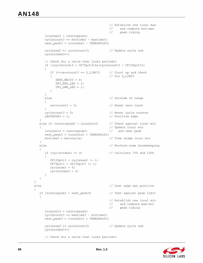
AN148
68 Rev. 1.3
// Establish new local max // and compute min-max // peak timing localmax3 = runningsum3; cyclecount3 += mintime3 - maxtime3; next_peak3 = localmax3 - THRESHOLD3;
cyclesum3 += cyclecount3; // Update cycle sum cycleindex3++;
// Check for a value that looks periodic if ((cyclecount3 > CP75pct3)&&(cyclecount3 < CP150pct3)) { if (++zerocount3 == Z_LIMIT) // Count up and check { // for Z_LIMIT ZERO_WAIT3 = 0; TK3_RED_LED = 1; TK3_GRN_LED = 1; } } else // Outside of range { zerocount3 = 0; // Reset zero count } cyclecount3 = 0; // Reset cycle counter LASTEDGE3 = 1; // Positive edge } else if (runningsum3 < localmin3) // Check against local min { // Update local min localmin3 = runningsum3; // and next peak next_peak3 = localmin3 + THRESHOLD3; mintime3 = maincycle; // Time stamp local min } else // Perform some housekeeping { if (cycleindex3 >= 3) // Calculate 75% and 150% { CP150pct3 = cyclesum3 >> 1; CP75pct3 = CP150pct3 >> 1; cyclesum3 = 0; cycleindex3 = 0; } } } else // Last edge was positive { if (runningsum3 < next_peak3) // Test against peak limit { // Establish new local min // and compute max-min // peak timing localmin3 = runningsum3; cyclecount3 += maxtime3 - mintime3; next_peak3 = localmin3 + THRESHOLD3;
cyclesum3 += cyclecount3; // Update cycle sum cycleindex3++;
// Check for a value that looks periodic

AN148
Rev. 1.3 69
if ((cyclecount3 > CP75pct3)&&(cyclecount3 < CP150pct3)) { if (++zerocount3 == Z_LIMIT) // Count up and check { // for Z_LIMIT ZERO_WAIT3 = 0; TK3_RED_LED = 1; TK3_GRN_LED = 1; } } else // Outside of range { zerocount3 = 0; // Reset zero count }
cyclecount3 = 0; // Reset cycle counter LASTEDGE3 = 0; // Negative edge
} else if (runningsum3 > localmax3) // Check against local max { // Update local max localmax3 = runningsum3; // and next peak next_peak3 = localmax3 - THRESHOLD3; maxtime3 = maincycle; // Time stamp local max } else // Perform some housekeeping { if (cycleindex3 >= 3) // Calculate 75% and 150% { CP150pct3 = cyclesum3 >> 1; CP75pct3 = CP150pct3 >> 1; cyclesum3 = 0; cycleindex3 = 0; } } } } // End of Waiting for Zeroes code (before Z_LIMIT reached) } // End While (!READ_TIMEOUT)
// Finish off last bytes with zeros.. while (bytecount1 < 8) { Temp_Byte1 = Temp_Byte1 << 1; Temp1_b0 = 0; // record a zero bytecount1++; } T1RAW[COLLECTED1] = Temp_Byte1;
while (bytecount2 < 8) { Temp_Byte2 = Temp_Byte2 << 1; Temp2_b0 = 0; // record a zero bytecount2++; } T2RAW[COLLECTED2] = Temp_Byte2;
while (bytecount3 < 8) { Temp_Byte3 = Temp_Byte3 << 1; Temp3_b0 = 0; // record a zero

AN148
70 Rev. 1.3
bytecount3++; } T3RAW[COLLECTED3] = Temp_Byte3;
return (1);}
//-----------------------------------------------------------------------------// TrackErrorCheck//-----------------------------------------------------------------------------//// This routine checks the decoded track data for Start Sentinel, End Sentinel,// Parity, and LRC errors.//
char TrackErrorCheck (unsigned char maxindex, unsigned char StartSen, unsigned char EndSen, unsigned char CharBits){unsigned char idata ASCII_Index, ASCII_Mask;unsigned char idata ASCII_Data, PC_count, Read_LRC = 0, Calc_LRC = 0;char idata errorcode = 0;bit ES_Found = 0, ParityCheck = 0;
ASCII_Mask = 0x7F >> (8 - CharBits); // Mask used to separate data info
if (ASCII_array[0] != StartSen) // Check for SS at start of array { errorcode |= 0x81; // ERROR - SS is not 1st character }
// Loop through ASCII_array and check each byte for errors for (ASCII_Index = 0; ASCII_Index <= maxindex; ASCII_Index++) { ASCII_Data = ASCII_array[ASCII_Index]; if (!ES_Found) // If ES not found yet { // LRC Check - XOR’s data from all bytes (except the LRC) Calc_LRC ^= (ASCII_Data & ASCII_Mask);
if (ASCII_Data == EndSen) // If this is the End Sentinel, { // treat the next character as // the LRC, and signal that // the ES has been found Read_LRC = (ASCII_array[ASCII_Index+1] & ASCII_Mask); maxindex = ASCII_Index+1; ES_Found = 1; } }
// Parity Check - checks #1’s against Parity bit for ODD parity. ParityCheck = 0; // Reset parity check variable for (PC_count = 0; PC_count < CharBits; PC_count++) { ParityCheck ^= (ASCII_Data & 0x01); ASCII_Data = ASCII_Data >> 1; } if (ParityCheck == (ASCII_Data & 0x01)) {

AN148
Rev. 1.3 71
ASCII_array[ASCII_Index] |= 0x80; // Mark this byte for ID later errorcode |= 0x88; // ERROR - Parity error } }
// Check that End Sentinel was found in captured data if (!ES_Found) { errorcode |=0x82; // ERROR - End Sentinel never found } // If ES was found... else if (Calc_LRC != (Read_LRC & ASCII_Mask)) { errorcode |= 0x84; // LRC error
// Parity Check for LRC - checks #1’s against Parity bit for ODD parity. ParityCheck = 0; // Reset parity check variable for (PC_count = 0; PC_count < CharBits; PC_count++) { ParityCheck ^= (Read_LRC & 0x01); Read_LRC = Read_LRC >> 1; } if (ParityCheck == (Read_LRC & 0x01)) { ASCII_array[maxindex] |= 0x80; // Mark LRC byte for ID later errorcode |= 0x88; // ERROR - Parity error } }
// If no errors were detected, return the number of bytes found. // Otherwise, return the error code. if (errorcode == 0) { return ASCII_Index; } else { return errorcode; }
}
//-----------------------------------------------------------------------------// DecodeTrackForward//-----------------------------------------------------------------------------//// This routine is used to decode a track into characters, assuming it was// recorded in the forward direction into the array.//
char DecodeTrackForward (unsigned char maxindex, unsigned char Byte_Offset, unsigned char Bit_Offset, unsigned char *TrackRAW, unsigned char CharBits){unsigned char idata Track_Index = 0;char idata ASCII_Index = 0, ASCII_Mask;unsigned char idata Track_Data, ASCII_Data;unsigned char idata Track_bit, ASCII_bit;
// Reset temporary variables

AN148
72 Rev. 1.3
ASCII_bit = 0x01; ASCII_Data = 0x00;
// Generate a bit comparison value for sorting through ASCII bytes ASCII_Mask = 0x01 << (CharBits-1);
// Begin at the specified offset, and proceed until the end of the track for (Track_Index = Byte_Offset; Track_Index <= maxindex; Track_Index++) { // Grab a byte of raw data Track_Data = TrackRAW[Track_Index];
// Unpack raw data byte into character(s) for (Track_bit = Bit_Offset; Track_bit != 0x00; Track_bit = Track_bit>>1) { if (Track_bit & Track_Data) { ASCII_Data |= ASCII_bit; } else { ASCII_Data &= ~ASCII_bit; } if (ASCII_bit != ASCII_Mask) { ASCII_bit = ASCII_bit << 1; } else { ASCII_bit = 0x01; ASCII_array[ASCII_Index] = ASCII_Data;
if ((ASCII_Data == 0x00)||(ASCII_Index == 126)) { Track_Index = maxindex; // end translation }
ASCII_Index++; } } }
// Return the number of characters unpacked return (ASCII_Index);
}
//-----------------------------------------------------------------------------// DecodeTrackBackward//-----------------------------------------------------------------------------//// This routine is used to decode a track into characters, assuming it was// recorded in the backward direction into the array.//char DecodeTrackBackward (unsigned char Byte_Offset, unsigned char Bit_Offset, unsigned char *TrackRAW, unsigned char CharBits){unsigned char idata Track_Index;char idata ASCII_Index = 0, ASCII_Mask;

AN148
Rev. 1.3 73
unsigned char idata Track_Data, ASCII_Data;unsigned char idata ASCII_bit;
// Reset temporary variables ASCII_bit = 0x01; ASCII_Data = 0x00;
// Generate a bit comparison value for sorting through ASCII bytes ASCII_Mask = 0x01 << (CharBits-1);
// Begin at the specified offset, and proceed until the beginning for (Track_Index = Byte_Offset; Track_Index != 0x00; Track_Index--) { // Grab a byte of raw data Track_Data = TrackRAW[Track_Index];
// Unpack raw data byte into character(s) while (Bit_Offset != 0x00) { if (Bit_Offset & Track_Data) { ASCII_Data |= ASCII_bit; } else { ASCII_Data &= ~ASCII_bit; } if (ASCII_bit != ASCII_Mask) { ASCII_bit = ASCII_bit << 1; } else { ASCII_bit = 0x01; ASCII_array[ASCII_Index] = ASCII_Data; ASCII_Data = 0; ASCII_Index++; } Bit_Offset = Bit_Offset << 1; } Bit_Offset = 0x01; }
// Finish off last byte with trailing zeros ASCII_Mask = ASCII_Mask << 1; while (ASCII_bit != ASCII_Mask) { ASCII_Data &= ~ASCII_bit; ASCII_bit = ASCII_bit << 1; } ASCII_array[ASCII_Index] = ASCII_Data;
// Return the number of characters unpacked return (ASCII_Index);
}
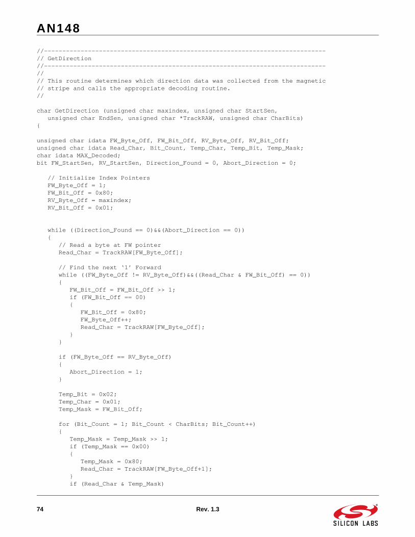
AN148
74 Rev. 1.3
//-----------------------------------------------------------------------------// GetDirection//-----------------------------------------------------------------------------//// This routine determines which direction data was collected from the magnetic// stripe and calls the appropriate decoding routine.//
char GetDirection (unsigned char maxindex, unsigned char StartSen, unsigned char EndSen, unsigned char *TrackRAW, unsigned char CharBits){
unsigned char idata FW_Byte_Off, FW_Bit_Off, RV_Byte_Off, RV_Bit_Off;unsigned char idata Read_Char, Bit_Count, Temp_Char, Temp_Bit, Temp_Mask;char idata MAX_Decoded;bit FW_StartSen, RV_StartSen, Direction_Found = 0, Abort_Direction = 0;
// Initialize Index Pointers FW_Byte_Off = 1; FW_Bit_Off = 0x80; RV_Byte_Off = maxindex; RV_Bit_Off = 0x01;
while ((Direction_Found == 0)&&(Abort_Direction == 0)) { // Read a byte at FW pointer Read_Char = TrackRAW[FW_Byte_Off];
// Find the next ‘1’ Forward while ((FW_Byte_Off != RV_Byte_Off)&&((Read_Char & FW_Bit_Off) == 0)) { FW_Bit_Off = FW_Bit_Off >> 1; if (FW_Bit_Off == 00) { FW_Bit_Off = 0x80; FW_Byte_Off++; Read_Char = TrackRAW[FW_Byte_Off]; } }
if (FW_Byte_Off == RV_Byte_Off) { Abort_Direction = 1; }
Temp_Bit = 0x02; Temp_Char = 0x01; Temp_Mask = FW_Bit_Off;
for (Bit_Count = 1; Bit_Count < CharBits; Bit_Count++) { Temp_Mask = Temp_Mask >> 1; if (Temp_Mask == 0x00) { Temp_Mask = 0x80; Read_Char = TrackRAW[FW_Byte_Off+1]; } if (Read_Char & Temp_Mask)

AN148
Rev. 1.3 75
{ Temp_Char |= Temp_Bit; } else { Temp_Char &= ~Temp_Bit; } Temp_Bit = Temp_Bit << 1; }
// Check character against Start Sentinel if (Temp_Char == StartSen) { FW_StartSen = 1; } else { FW_StartSen = 0; }
// Read a byte at RV pointer Read_Char = TrackRAW[RV_Byte_Off];
// Find the next ‘1’ Reverse while ((FW_Byte_Off != RV_Byte_Off)&&((Read_Char & RV_Bit_Off) == 0)) { RV_Bit_Off = RV_Bit_Off << 1; if (RV_Bit_Off == 00) { RV_Bit_Off = 0x01; RV_Byte_Off--; Read_Char = TrackRAW[RV_Byte_Off]; } }
if (FW_Byte_Off == RV_Byte_Off) { Abort_Direction = 1; }
Temp_Bit = 0x02; Temp_Char = 0x01; Temp_Mask = RV_Bit_Off;
for (Bit_Count = 1; Bit_Count < CharBits; Bit_Count++) { Temp_Mask = Temp_Mask << 1; if (Temp_Mask == 0x00) { Temp_Mask = 0x01; Read_Char = TrackRAW[RV_Byte_Off-1]; } if (Read_Char & Temp_Mask) { Temp_Char |= Temp_Bit; } else { Temp_Char &= ~Temp_Bit;

AN148
76 Rev. 1.3
} Temp_Bit = Temp_Bit << 1; }
// Check character against Start Sentinel if (Temp_Char == StartSen) { RV_StartSen = 1; } else { RV_StartSen = 0; }
if (FW_StartSen ^ RV_StartSen) { Direction_Found = 1; } else if (FW_StartSen && RV_StartSen) { //*** Check for ES Backwards in front Temp_Bit = 0x80; Temp_Char = 0x00; Temp_Mask = FW_Bit_Off;
MAX_Decoded = FW_Byte_Off; // MAX_Decoded used as temporary storage if ((Temp_Mask >> CharBits) != 0x00) { Temp_Mask = Temp_Mask >> CharBits; } else { FW_Byte_Off++; Temp_Mask = Temp_Mask << (8 - CharBits); }
Read_Char = TrackRAW[FW_Byte_Off]; for (Bit_Count = 0; Bit_Count < CharBits; Bit_Count++) { if (Read_Char & Temp_Mask) { Temp_Char |= Temp_Bit; } else { Temp_Char &= ~Temp_Bit; } Temp_Bit = Temp_Bit >> 1;
Temp_Mask = Temp_Mask >> 1; if (Temp_Mask == 0x00) { Temp_Mask = 0x80; Read_Char = TrackRAW[FW_Byte_Off+1]; } } FW_Byte_Off = MAX_Decoded; // Restore FW_Byte_Off
Temp_Char = Temp_Char >> (8 - CharBits);

AN148
Rev. 1.3 77
// Check character against End Sentinel // If found here, track is reverse. if (Temp_Char == EndSen) { FW_StartSen = 0; } //otherwise, it is forward else { RV_StartSen = 0; }
Direction_Found = 1; } else if (!Abort_Direction) { FW_Bit_Off = FW_Bit_Off >> 1; if (FW_Bit_Off == 00) { FW_Bit_Off = 0x80; FW_Byte_Off++; } RV_Bit_Off = RV_Bit_Off << 1; if (RV_Bit_Off == 00) { RV_Bit_Off = 0x01; RV_Byte_Off--; }
if (FW_Byte_Off >= RV_Byte_Off) { Abort_Direction = 1; } }
} // End while((Direction_Found == 0)&&(Abort_Direction == 0))
if ((Direction_Found)&&(!Abort_Direction)) { if (FW_StartSen) { MAX_Decoded = DecodeTrackForward(maxindex, FW_Byte_Off, FW_Bit_Off, TrackRAW, CharBits); } else if (RV_StartSen) { MAX_Decoded = DecodeTrackBackward(RV_Byte_Off, RV_Bit_Off, TrackRAW, CharBits); } } else { MAX_Decoded = 0x81; // Could not find Start Sentinel }
return (MAX_Decoded);
}

AN148
78 Rev. 1.3
//-----------------------------------------------------------------------------// UART_CharOut//-----------------------------------------------------------------------------//// This routine sends a single character to the UART. It is used in lieu of// printf() to reduce overall code size.//
void UART_CharOut (unsigned char c){ if (c == ‘\n’) { while (!TI0); TI0 = 0; SBUF0 = 0x0d; /* output CR */ } while (!TI0); TI0 = 0; SBUF0 = c;}
//-----------------------------------------------------------------------------// UART_StringOut//-----------------------------------------------------------------------------//// This routine calls the UART_CharOut repeatedly to send a string value to the// UART. It is used in lieu of printf() to reduce overall code size.//
void UART_StringOut (unsigned char *c){ while (*c != 0x00) { UART_CharOut(*c); c++; }}
#if DEBUG//-----------------------------------------------------------------------------// UART_HexOut//-----------------------------------------------------------------------------//// This routine sends the hexadecimal value of a character to the UART as ASCII// text. Only used when DEBUG = 1.//void UART_HexOut (unsigned char c){ while (!TI0); TI0 = 0; if ((c & 0xF0) < 0xA0) SBUF0 = ((c >> 4) & 0x0F) + 0x30; else SBUF0 = ((c >> 4) & 0x0F) + 0x37;
while (!TI0); TI0 = 0; if ((c & 0x0F) < 0x0A)

AN148
Rev. 1.3 79
SBUF0 = (c & 0x0F) + 0x30; else SBUF0 = (c & 0x0F) + 0x37;
}#endif // END #if DEBUG

AN148
Rev. 1.3 80
DOCUMENT CHANGE LIST:
Revision 1.2 to Revision 1.3 Corrected code in Appendix E-Firmware Listing for
2-Channel Example.
Corrected code in Appendix F-Firmware Listing for 3-Channel Example.

http://www.silabs.com
Silicon Laboratories Inc.400 West Cesar ChavezAustin, TX 78701USA
Simplicity Studio
One-click access to MCU and wireless tools, documentation, software, source code libraries & more. Available for Windows, Mac and Linux!
IoT Portfoliowww.silabs.com/IoT
SW/HWwww.silabs.com/simplicity
Qualitywww.silabs.com/quality
Support and Communitycommunity.silabs.com
DisclaimerSilicon Labs intends to provide customers with the latest, accurate, and in-depth documentation of all peripherals and modules available for system and software implementers using or intending to use the Silicon Labs products. Characterization data, available modules and peripherals, memory sizes and memory addresses refer to each specific device, and "Typical" parameters provided can and do vary in different applications. Application examples described herein are for illustrative purposes only. Silicon Labs reserves the right to make changes without further notice and limitation to product information, specifications, and descriptions herein, and does not give warranties as to the accuracy or completeness of the included information. Silicon Labs shall have no liability for the consequences of use of the information supplied herein. This document does not imply or express copyright licenses granted hereunder to design or fabricate any integrated circuits. The products are not designed or authorized to be used within any Life Support System without the specific written consent of Silicon Labs. A "Life Support System" is any product or system intended to support or sustain life and/or health, which, if it fails, can be reasonably expected to result in significant personal injury or death. Silicon Labs products are not designed or authorized for military applications. Silicon Labs products shall under no circumstances be used in weapons of mass destruction including (but not limited to) nuclear, biological or chemical weapons, or missiles capable of delivering such weapons.
Trademark InformationSilicon Laboratories Inc.® , Silicon Laboratories®, Silicon Labs®, SiLabs® and the Silicon Labs logo®, Bluegiga®, Bluegiga Logo®, Clockbuilder®, CMEMS®, DSPLL®, EFM®, EFM32®, EFR, Ember®, Energy Micro, Energy Micro logo and combinations thereof, "the world’s most energy friendly microcontrollers", Ember®, EZLink®, EZRadio®, EZRadioPRO®, Gecko®, ISOmodem®, Precision32®, ProSLIC®, Simplicity Studio®, SiPHY®, Telegesis, the Telegesis Logo®, USBXpress® and others are trademarks or registered trademarks of Silicon Labs. ARM, CORTEX, Cortex-M3 and THUMB are trademarks or registered trademarks of ARM Holdings. Keil is a registered trademark of ARM Limited. All other products or brand names mentioned herein are trademarks of their respective holders.