Embed Size (px)
Citation preview

HWAHAK KONGHAK Vol. 39, No. 1, February, 2001, pp. 1-8(Journal of the Korean Institute of Chemical Engineers)
������� � �1. �� �� ����
������������* †�� �
����� �����*����� �����
(1999 2� 23� ��, 2000 3� 24� ��)
An Optimal Design of Crude Distillation UnitPart 1. Determination of Optimal Feed Tray Locations
Jung Won Seo, Suk Joon Kim, Kyung Hyun Kim, Min Oh*† and Tae Hee Lee
Department of Chemical Engineering, Yonsei University, Seoul, Korea*Department of Chemical Engineering, Hanbat National University, Taejon, Korea
(Received 23 February 1999; accepted 24 March 2000)
� �
�� �� ���� � � � ���� ��� ��� ���� � ������� !�" #$ %&� '(�)
*. +, !�-. / 150,000 BPSD0 ������ !1 ��23 45 67 8�9� � ':$ ;<� =>�,
��� ��� #�? �@A B$C'� %�C�"D MINLP E�� FG�H �� � I� F�)*. #$?J�� K
�H #$ �LM3 !1 ��20 NO9 P pumparound0 #$ Q�� R� ' �S*. T"U %&VW0 4X 2Y0
9/Z [\� ]�^S�� _`� ��20 a9� bc ' �S*. !1 ��23 8�90 #$ �LMd ee 34M3 14
M�S�� !1 ��20 NO9 Q�� f 15% �@ ]�g ' �h� i ' �S*. j� �k0 l� m' -n�o �
p pumparound Q�� f 37% �- qr ' �S*.
Abstract − As a crude distillation unit(CDU) is one of the important processes in refinery industries and consumes enormous
energy, an optimal design of a CDU was attempted. The target CDU is under commercially operated and its capacity is 150,000
BPSD. The mathematical models for an atmospheric distillation column(ADC) and naphtha stabilizer were established and we
formulated the objective function so as to minimize the energy consumption. The optimal feed locations of both the atmo-
spheric distillation column and stabilizer were obtained by solving mixed-integer nonlinear programming problems. The opti-
mal duties of condenser and pumparound in the ADC were determined by the optimization task. In the case of optimal design,
vapor and liquid load was apparently decreased and the size of the ADC and the stabilizer was accordingly decreased. The opti-
mal feed tray of ADC and stabilizer were 34 and 14 respectively, and the condenser duty of the ADC was decreased by the
amount of 15% and the duty of pumparound, which permits heat recovery, was increased by the degree of 37%.
Key words: Optimal Design, Crude Distillation, Feed Tray, Simulation, MINLP
†E-mail: [email protected]
1. �
�� ����� 1857� �� �[1] � � �� ��� �� �
����, �� �� � ���� �� �� !��" #$. �
��% &�'� �� (�) 1995�' ** 42.2 +, -.'� 2015
�' ** 52.3 +, -.� /�0 12� 3456, (� /� 7
897: (;9< ��� =>�" #$[2]. &? @A Table 1'
BC DE F� 1990-1996� G�' �HI 12.5% JK� �� (�
� LMN2� /��" #) OP�6, 1997� Q RS AT �U
��/V WJXY) ** 2,438Z -.' �[$[3].
��/V��� �� ���� \]^_�� B$ �`� W_E
@�NC a3� bc de� �� !�: f�g h(N�$. ij
�� ��') 'k> � �� Jl mn oT" p@ X�' 8
� 8q r sta <�u� L= v�5" #) OP�$. wU� 8
x @yz: {�" i8 �|: }: ( #~�, �� �� WJ �
�� i8� �l��� 'k> �J i�� 0 ( #) a3 ��
: W�� �s� �$.
�� ��� ^f �] �����, �� �c: !��� ��N
1

2 �������������� �
te
2� 3p�~� �u� Nm� -�5s #$. �� � �� W_) �
�NC ]�2�� ���s ��" � ��E ��' Nl�g
��a �c: !���� �� �c �� Rd�� ��\�~�
�) 1�$[4]. ��� �� W_ �� ��� ��M �N: ,�\�
) W_ ( ¡� ¢ �£U �� ¤¥~ ¦�� §¨ ©ª�g
� �) iN� <�� p�0 ( #$. $\ Q��, �«2�) s¬
��u� h��6, �u: s� �¡0 1C� ¡��g� �",
$[ �«2�) � ��u ®�� a3 ��u: ¡��g� �$
) 1�$. 3¯) °�± ¡� ( ²³�" #2´� (�N2�
µ��( J©§ _¶·(MINLP) <�� �¸¹$. ��/V��� '
k> �J� º ��2� g� �> »� ��2� �¼s½ #s 3�
\¾¿' 8� �ÀNC ����� Á> Â26 wU� iN� ]�
' g� <�L: �>" #$. RSÃ> ��/V�� W_ � a3
(Ä� Å>£s @Æ�� �Ç% W_ �� �� �� YG È
»' �g �¼sM 1� *ÈN�É$. ij �� \¾¿ �� Ê
[ 32� �� 3� YG � iN�' 8� �¦� Ë� �¼s
Ì>, Liebmann r[5]� >N�ÍÎ� ��/V��' 8�g) �8
N2� o (� N26, o ��) �8 ��ÏG � o _Ð ÏGu'
�g � 7� 897 �Ñ� ��5> Â� Ò<�U 0 ( #$.
��/V�� iN W_ �Ñ `B) 'k> mn ��) �Ó
�ÑN ÔÕ�U) �'�~ o � ®$" 0 ( #$.
*ÈN2� ���¨ /V��' 8� iN� <� Ö �> �§2
� �× ( #$[6]. ØÙ, i� Jl �� i� 'k> Gl2� ��
) �Ú: �¼� f� iN a3 ��: ¡��) <��$. BÛ Ô
Õ (�) ~Ü Ý, Þ� ¤¥, !�� ¤¥ r�$. ��) �Ú�ß
*ÈN2� �7 ��M à~ �� ���9á Ï(K: �¸?6,
�E F� ¦�% iN� <�) J©§ _¶·(NLP) <�� â¡%$.
ãäÙ <��), �] �� ¢ �£U 7T' h�� i� ^ ( ¡
�: ²³�) <�� ^� °�± (�� Ò<' MINLP <�� %
$. �å �§ <�'�) W�JE a3J� Yã "t56, ^ (
� æ ?9 �À /�' wU W�J� /��) È� a3J) s¬
\LÃ>) n��) 1� *ÈNC @��$. ç>è2�, ^ (E �
� ~Ü^ � éV -ê^ iN f� ¦�) <��� � @A ë
\ MINLP <��$.
ì �¦) �� �� WJ i8� �>��� 'k>� Jl:
iN� �t) í' �L: ã" #2´�, î'� ïð� /V��'
8� W_ �§ � ØäÙE PäÙ @A' �ñ%$. iN� �·:
�l�g /Væ ��^ f�E �� 3�' 8�g ��) �Ú:
ò�� f� iN a3 ��: ¡��"¯ �Í$. 8� ��� RS
a35" #) 150,000 BPSD XY ��/V��2�� �� óÝ�
�, �ô /Væ, @c �õ¸ Ç��, nô /Væ r2� ¦�%$. 3
� ��' 8� iN a3 �� ¡�' ö� <�) �29[7]'� $
¼É$.
��/V�� �_NC W_ f�g g� ÷·' � �¦� >
±5s ø26[8-11] iN� �·: �l�g W_ <� �¡�t)
iù úz � ��) SrygleyE Holland[12]' �g (Ä5É$.
� �¦'�) �sM �� ��2�9á /Væ i� ^( ¡�
�Í$. SargentE Gaminibandara[13]) �� ¤¥~ ©ª <� û
ü2� $¼s, �sM 7T �KN2� �� f� iN /Væ ¦
� §¨ ¡��) B$ *È�% <� �¡�Í$. iN �� ~Ü
^: ¡��� f�g Viswanathan� Grossmann[14]� MINLP <�
�Ç�g Ö �> /Væ' Nl�Í26, Seo r[15]� � ��/V
æ' Nl�Í$.
ì ý<'�) ��/V�� iNW_ *p2� �� /V�� �
�ô /Væ� @c �õ¸ Ç�� iN ��^: ¡��Í$. /
Væ 'k> �J i�� �~� �N³( W��" /Væ' 8
� (�N Yþ: Pÿ2�� MINLP <� ¦��Í$. _�' h�
� ¯�) �� ���C �� �� ¯� �l�Í$. �� ì �
¦ _� ¡� �/: f�g �l YG� �l� YG ¡�E J
��Í$.
2. ��� ��
iN� <�) ql' #s ���� ¢ �£U �T, @�, �Û r
g� 7�'� Nl5" #>, <� (�NC ¦� � �·� ��
�ñ� J�� ¦� >$. ��' #s ��� �G�� iN� �
· ' ®� �g�Í$. �� �� �_NC W_� �©: f
�g Gl5) iN� �· *ÈN2� ã �> <� �§2� �× (
#$. ��) NLP��, �N³( �� ����� <� (u J©
§ �±³(� ¦�5s #$. $[ � �>) î ØäÙ @A' �
�g, �� �� �� J�±NC �c(ó us /Væ ^():
R�) �( �� 0� 1 ã �> �: �0 ( #) (� ²³5
)í � MINLPU" �6 *ÈNC §¨) $ü� F$[16, 17].
s.t.
Ax = a
(1)
g�� x) �À, �~, ôz r: �¸?) �± ( �á�", y)
�� �S 0-1� �¸?) �á�$. MINLP <��9á �M
( y ���� NLP <�� p%$. f(x), h(x) oT" g(x)) ��
�N³(, ÷�� oT" 9r ����� �ö% J©§ ³(�$.
NLP <�'�) SQP(successive quadratic programming) �"T��
�� �T ��)í, ��· _Ý �� Ò<' È»_� (� $[
g¸ ÷·' J�g �r� N$) ��: �>" #$. B$ º X
Y <� �� f�g) rSQP(reduced Hessian SQP)·� �l%$.
MINLP <�' 8� �·� ®� branch and bound·, GBD(generalized
Benders decomposition)· oT" OA(outer-approximation)· r2� �
× ( #$[18].
Branch and bound �"T�� �� � % µ��( _¶·(MIP)
��·2� LandE Doig[19]' �g �Ç5s Dakin[20]' �g
��� 5É$. GBD·� OA· @A'~ �· ����'� � ÷
·' ��´�, Branch and bound·� MINLP �· �ù �¼
" #$" 0 ( #$. o�� Branch and bound ÷·' � MINLP
�·� �8N2� �� ( NLP 9<� � ¦�� �6, wU�
minzx y,
= cTy f x( )+
h x( ) 0=
g x( ) 0≤
By Cx d≤+
x X∈ x x Rn∈ xL x xU≤ ≤,{ }=
y Y∈ y y 0 1,{ }m∈ Ey e≤,{ }=
Table 1. Trends of petroleum demand in Korea
1990 1991 1992 1993 1994 1995 1996 Average annual growth ra
Gross consumption[106 bbl] 356.3 424.7 514.2 546.6 621.5 677.2 721.2 -Growth rate[%] 124.1 119.2 121.1 19.8 110.1 119.0 116.5 12.5
���� �39� �1� 2001� 2�

������� �� �� 3
_�: f� Jl� �� �$) L� ̂ L2� B"5" #$. Benders
[21]) G(projection)E !�(relaxation)' �ù� �·: "Ç�Í)
í, � ÷·'�) �sM <� ã � ÔÕNC iN� <�� 7
0�g ou � È» _�: (ij2�� � ¦�$. Geoffrion[22]
� � ÷·: *È� �g GBD·: �Ç�Í26, <� »"�� ,
#) �( (� #) MIP <� xy-��� � y-��2� ��³
2�� �( ( ÔÕN2� ¦0 ( #$. � �"T�� !�% �
<�(master problem)E $�¾ J©§ 9 <�(subproblem) � �
8� ¦�)í $( È»_�' � (e ±~� %T$) 1� ^
L2� ]l�$.
OA �"T�� Duran� Grossmann[23]' �g ûü �Ç5É$.
� ÷·� GBD·� F� GE !�' �ù�6, � �% È»_�
'� �( (� "�% NLP 9 <� �·� !�% � <� �·2
� ¦�%$. NLP 9 <�) �� �� ¤¥~' 8� �± ( i
N��, MINLP <�' 8� �N³( ���: ���$. MILP �
<�) �&> ¤¥~ �'� �� '� �� �: () ¦� ©ª�
� 56 � �� �� )� ���B$ * @A MILP � <�) ��
�� %$.
J©§ ÷��: ����, �) OA �"T� ^L: B!��
f� ÷·Ó2�� equality relaxation(OA/ER) �"T�� �5É$
[17]. � ÷·� î ÷·� F� _� �K: �>�� +\N2� �
¸¹ J©§ r����: $, ( #$. o�� � ÷· �� ^L:
�>" #)í, MILP � <� ®�� GBD· @AB$ Rd� ®
$) L�$.
OA/ER: �©�� f�g `�% -�.(augmented penalty) ³(
¡�� ��a MILP � <�� Viswanathan� Grossmann[24]' �
g �Ç5É$. � AP/OA/ER �"T�� DICOPT++(DIscrete Con-
tinuous OPTimizer)U) -�>� õ�o/� 5s iN� õ�o/ ï
sC GAMS[25]'� Gl0 ( #$. RS iN� �· : "
t�g, $ü m'� ���% MINLP <�) AP/OA/ER �"T�:
�l�g GAMSE o' ±� solver �l�g �É$.
3. ����
3-1. ����
ì �¦ f� 8� ��� &? Å>£s0 ÏG� W_�g RS
�1�'� a3�" #) ** !�À 150,000 BPSD ��2�, ��
/V�� �ì� 5) �ô /V��, nô /V��, �� óÝ��
r 3� �� ��2� �¼sÌ$. ��' 8� ¯P� �Ñ� ì ý
< 29[7]' �¸?É$.
�ô /Væ� 2 � pumparoundE 2 � éV 3���� ¦�
56, �� �ô �'� �±N2� /V³2�� @c �õ¸, �c
�õ¸, kerosene, LGO(light gas oil), HGO(heavy gas oil) r: !��
$. ��) pumparound � !�� ¤¥� Ý�p: Û�g �Ý56,
i�N2� �Ý�'� ��) �~� �Ý5s �� /Væ2� us
�$. @c �õ¸) Ç�� Û�g �4a �7� ��%$. Pump-
around reflux) æ2�9á 5� éV 6� ?6 Ý�p: Û�g
Þ��g éV^ f 972� 57T) 1�$. Pumparound) �
T�, Þ�% 5�� æ �� 97' ~Ü82�� 7TU) é�'
�) °T�>, {� �~'� Ý� �� �Ý�) í' �92
��, �� �Ý� 9� :* ( #26, æ �9C q;� 9�
n�\< q;� ®� :�)í =A ��� ë0: �$. �'
��g æ ?9 �� �ë'� �>5 ¤¥: I*�� �>\<
: (� #", �) /Væ ?@ n� �½E æ W�Jl: n
�\�)í ¡�NC ��� ]l�$[11, 26]. wU� pumparound l
À ¡�� �� W_' �� ��� (� ��� ]l�6 �
W_ (� �� iNa3��: ¦�) 1� =A #) *�U
0 ( #$. ì �¦ #s æ ¦�E a3 ��� �� �� ¯
��9á ¦�Í" Table 2E 3' �¸?É$.
3-2. �� � �� �
���¨ YG � iN�' #s� � ¤¥ Ýë�N ��: �`
� _��) 1� ���$. ��) @�(� ���u »"� µ�
Table 2. Column configuration
Numbers of traysMain columnLN stabilizerHN side-stripperKerosene side-stripperLGO side-stripperHGO side-stripper
LocationsFeed for main columnFeed for LN stabilizerStripping steam of main columnHN pumparound draw and returnKerosene pumparound draw and returnLGO pumparound draw and returnHGO pumparound draw and return
353014121212
3317359, 8
18, 1724, 2328, 27
Table 3. Operating conditions
Stripping steamMain column
TemperaturePressure Flow rate
Kerosene side-stripper
[oC][kgf /cm2][kmol/h]
1704.63
555.1
TemperaturePressureFlow rate
LGO side-stripper
[oC][kgf /cm2][kmol/h]
170 4.63138.8
TemperaturePressureFlow rate
HGO side-stripper
[oC][kgf /cm2][kmol/h]
1704.63
238.7
TemperaturePressureFlow rate
[oC][kgf /cm2][kmol/h]
1704.6394.4
PumparoundHN
Flow rateReturn temperatureDuty
Kerosene
[kmol/h][oC][106kcal/h]
3,333.870
−14.9381
Flow rateTemperature dropDuty
LGO
[kmol/h][oC][106kcal/h]
1,286.440
−4.9884
Flow rateTemperature dropDuty
HGO
[kmol/h][oC][106kcal/h]
1,481.850
−9.9891
Flow rateReturn temperatureDuty
[kmol/h][oC][106kcal/h]
725.3286.5
−8.0028
HWAHAK KONGHAK Vol. 39, No. 1, February, 2001
4 �������������� �
�� �¼s½ #s� BÛ A)L �~ Bf' wU ��NC �7
2� �C� %$. �) �� �V' wU $D� Ò<' �`� 7
�� h��6 ��� 7�') TBP(true boiling point) E©, light end
7�, API(American petroleum institute) J� r: Û�g �¼sM$.
�x' �cÀ, F~, L~ r ¯� Û�g �G �`� 7�: 0
( #$. ì �¦'� Gl� ��) �UJ� @c��� API J��
33.1�6 H(�7� ���7: ��g 12� �72� �Cs _�
�Í$. �� ��: Table 4' �¸?É$.
Ýë�N ��: _��� f�g SRK(Soave-Redlich-Kwong) Yþ
� GS(Grayson-Streed) Yþ[27]: ��� 5�' �� Nl�Í$.
SRK Yþ� RK(Redlich-Kwong) �¨÷��' �ù�g Soave' �
g (�% 12�, �sM _' 8� µ�� ��� _�0 ( #
$. GS Yþ� Chao-Seader ö_[28] B$ I� Bf �~E ôz
Bf' `�� 12� µ�� H§_((K-value) _��) í' �
C$. SRK �¨÷��� P � �j: ()í, �� �� º �� �
� ô;C¯� 56, ��9á ô;C¯� R% �� $[ Ýë
�N ��u: _�0 ( #$.
µ�� � �7 i H§ _( Ki) $ü� F$.
(2)
Chao-Seader[28]) @�(�E �4a �� µ��' 8� �Æ�
*È�% 8q�¨ �T �l�g φil: Tr, Pr oT" ω J2�
�¸?É$. �Ò 5� Ë�~ _() ScatchardE Hildebrand �
Xl5�Ó: �l�Í" �� K�\. _() RK(Redlich-Kwong) �
2� ¦�Í$. Grayson-Streed[27]) _( (��g B$ {� �
~E ôz' Nl0 ( #~� �Í$. _�% 5� K�\. _(
E $[ Ýë� �c� �öö_�: �l�g 5� $[ Ýë
�N ��u: _�0 ( #$.
3-3. ���� �� �
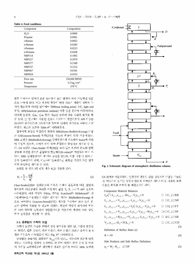
(�N Yþ (Õ: f�g �ô /Væ: *È ^, ¾L� �ð5
) i�^, �� �ð^, éV -ê^, éV ~Ü^ oT" q;� r 6
� 972� �CÉ26 �) Fig. 1' �¸?É$.
/Væ� q;� ²³�g Nmax� ^2� �¼s½ #26 ^
äM) � ^: ��g /��$. � ^' 8�g �c (> � 'k
> (> "t�Í26 Ýë�N �c� î'� ý� SRK Yþ�
GS ö_ �l�Í$. Ç�� @A~ F� ÷�2� Yþ: ,uÉ
$. Ç�� @A) éV� N26 i�^� SJ��$. $ü Yþ
�u� iN� <� r ����� %$.
Component Material Balances
(3)Definition of Reflux Ratio (r)
(4)
Side Products and Side Reflux Definition
(5)
K iyi
xi
----γiφi
l
φ̂iv
--------= =
fstzcst L j 1– xc j 1–, Bxc j, V jyc j, 0 ∀ C∈ j RB∈,=––+
L j 1– xc j 1–, V j+1yc j+1, L jxc j, V jyc j, 0 ∀ C∈ j NP∈,=––+
L j 1– xc j 1–, V j+1yc j+1, f jzcf L j– xc j, V jyc j, 0 c∀ C∈ j FT∈,=–+ +
L j 1– xc j 1–, V j+1yc j+1, L j– xc j, V jyc j, Wjxc j,– 0 c∀ C∈ j SP∈,=–+
L j 1– xc j 1–, Rjxc j−1, +Vj+1yc j+1, L– jxc j, V jyc j, 0 c∀ C∈ j SR∈,=–+
V j+1yc j+1, L j D+( )– xc j, 0= ∀ C∈ j CD∈,
R rD=
pj Wj Rj 1– j SP∈–=
Table 4. Feed conditions
Component Composition
H2O 0.0000Propane 0.0061i-Butane 0.0052n-Butane 0.0283i-Pentane 0.0215n-Pentane 0.0438NBP114 0.1965NBP227 0.2979NBP377 0.2180NBP537 0.1152NBP667 0.0341NBP824 0.0333
Flow rate 150,000 BPSDPressure 3.5 kgf /cm2
Temperature 370oC
Fig. 1. Schematic diagram of atmospheric distillation column.
���� �39� �1� 2001� 2�

������� �� �� 5
(6)
Energy Balances
(7)
Pumparounds Heat Duty Definition
(8)
3-4. ��� ��
iN� <�) i8� �� i�� 5sc �N³(E ����2�
¦�%$. �O �Ñ% DE F� /Væ� 'k> �J� ®´� 'k
> Ï(' ö� �: �N³(� "t�Í$. Ý Ï() pumparound
Û�g �¼s>6, Ï(% Ý� æ' ~Ü5) �� �Ý�)í �
l%$. iN �� ~Ü ^ f�E pumparound iN lÀ: ¡�
�� f�g $ü� F� �N³( ,uÉ$.
(9)
Ç�� @A) $ü� F� SJ� lÀ: i�� �~� �N
³( �P$.
(10)
3-3m' �¸Q r ����� ³R iN� <� !�: f�g W
_ � a3 ����� �S�$. ��^� S ( #) ^ Bf
) 2TjTTR−1�6, �� �� � ' f�� éV f�(7̂ )B$ ]
�� �´� o Bf) � :sus 2TjT6� %$. Fig. 1' BC
DE F� ��) � UB ^2� �Vs ~Ü%$" ���6, �
� �� ^� ��^2� ¡�%$.
� 7T% ¤¥� �� �À: ù�0 ( N", o �� �� �À�
F$. � (�2� R�� $ü� F$.
(11)
(12)
(13)
f �u� ^ �� ��^: ©ª�) O�6 �� C�g MINLP
<�� %$. æ ? ôz� $ü� F� ©§2� 7²�$" ��
�$.
(14)
g�� oT" P1) �sM ��$.
o W' �� �� �TNC �� Ò<' O� ����� h�
�$. !��u� ��� �¦�) Bf ? �: �½� �" æ ?
�� � 5� �À� J� b( �: �½� �$. �� iN
� <� �¡: f� SUN SPARCstation� Gl5É26 software�
) GAMS -�> �l�Í$.
4. � � ��
�� /Væ iN �� ~Ü^: ¦�� f� iN� ]� ¡�
Table 5' �¸?É$. �� iN� ¡�(optimal case) `C��
f�g g� $[ @A(base case, Case I, Case II)' 8� �� YG
(Ä�Í26 � Table 5' ³R �¸?É$. Table 5' �¸¹ ü(
�� æ ?9 Ý� x9� ÷ê5) 1: O�6 o m8�� *
(� ���Ý: f� preheat train'� ��E Ý�p� �� �
¼sX: �¸Q$.
�ì @A(base case)) �� �� W_ \ Gl5ÉY ¯�' �ù�
12� PRO/II[29] Gl�g ���¨ YG (Ä� ¡��$. ��
@A Case I� Case II) iN� @AE J� f�g a3 ��:
�\< ���¨ YG � ¡��$. Y� @A !�� ��� �
*�� �>�~� �Í$. 8� �� �� �� ~Ü^� 33̂ Cí
È�g, iN� ¡� ��^� 34̂ 2� _�5É$. �N³( �: J
��g B� iN�% @A� �� ��C �ì @A B$ ��5Éü
: 7+� � ( #$. iN�% @A) �ì @A' J�g q;� l
À: 15% �~ :* ( #26, "� ÝÏ( �Ú�� �) �*
� Z pumparound lÀ: Ð 37% /�\< �' 8� Ý Ï(
�Ú�� � [$. �� ~Ü^: 32̂ (Case I), 31̂ (Case II)2� �
\< YG� ¡� ë\ iN�% ¡�' J�g �N³( �� ��
5> Â\: ¢ �£U pumparound lÀ �� /�5> Âü: �
( #$.
æ ?9 ��E 5� ¤¥' 8� ¡� Fig. 2' �¸?É)í,
iN�% @A ¤¥� �ì @A(base case)' J�g ]� �¸�6,
�' wU æ ®� :* ( #$. �) �� /Væ ¯� ��J
� � �� r Jl mn' �g�� %$.
Fig. 3) iN�% ¡�' wU æ ?@: _��Í: ÒE �ì @
A J�� ¡� Bg�" #$. iN�% @A î'� ]^ì DE
F� æ ?9 ¤¥� n��g æ ?@� n��Í$.
iN�% @AE �ì @A æ �~ 7² Fig. 4' �¸?É$. �
_� �� � *��) ¡� Bg�" #26, �) æ �~ 7
²' ��: `) !��� =� B�> Â)$) 1: �¸Q$.
Rj 1– rkpj ∈=
fsthst L j 1– hj 1–
l Bhjl V jhj
v 0 j RB∈=––+
L j 1– hj 1–l V j+1hj 1+
v L jhjl V jhj
v 0 j NP∈=––+
L j 1– hj 1–l V j+1hj 1+
v f jhjf L j– hj
l V jhjv 0 j FT∈=–+ +
L j 1– hj 1–l V j+1hj 1+
v L j– hjl V jhj
v Wjhjl– 0 j SP∈=–+
L j 1– hj 1–l V j+1hj 1+
v R+ jhRj
l L j– hjl V jhj
v– 0= j SR∈+
L j D+( )hjl V– j+1hj 1+
v Qcon= j CD∈
Qk Rj 1– hRj 1–
l rkpjhjl ∀ SP∈–=
mimimize Qkk 1=
4
∑ Qcon–
mimimize Qreb
f j Fzj j FT∈≤
f j F=j TR∈∑
zj 1=j TR∈∑
Pj 1– 2Pj Pj 1+ 0 3 j Nmax 2–≤ ≤=+–
PNmax PNmax 1– P2, ,
Table 5. Optimal solutions for atmospheric distillation column
Design variable[106 kcal/h] Optimal case Base case Case I Case II
Objective function −3.2975 11.5550 6.3870 1-2.9433Duty of pumparound 1 −15.3742 −14.9381 −15.1433 −15.0669Duty of pumparound 2 −5.7817 −4.9884 −5.8042 -−6.9571Duty of pumparound 3 −13.3646 −9.9891 −10.7678 −11.4332Duty of pumparound 4 −10.9739 −8.0028 −8.8162 −8.8159Duty of condenser −42.1984 −49.4739 −46.9258 −45.2158Feed tray 34 33 32 1-1-.1-31
HWAHAK KONGHAK Vol. 39, No. 1, February, 2001

6 �������������� �
f ïð% iN� �·: Gl�g /Væ �� ~Ü^: ¡�0
( #É$. æ �~ 7² �� !��' ��: �> Â2�� iN�
]�: (Ä�g q;� lÀ� pumparound lÀ iN a3�:
}: ( #É" æ? ¤¥: n�\< æ ®�~ :* ( #É$.
Table 6� Ç��' 8� iN� ¡�(optimal case) Bg �" #2
6 �æ� ça�>� �ì @A(base case) � ã � YG¡�(Case
I, Case II)E J��Í$.
Ç�� �� �� ~Ü^� 17̂ (base case)�É)í, iN� ¡�
��^� 14̂ 2� _�5É$. �N³( �: J��g B� iN�%
@A� �� ��C �ì @A B$ ��5Éü: � ( #$. �� ~
Ü^: 15̂ (Case I), 16̂ (Case II)2� �\< YG� ¡� ë\ i
N�% ¡�' J�g �N³( �� ��5> Â\ü: � ( #$.
Ç�� ?9 ¤¥: Fig. 5' �¸?É)í �ì @AB$ iN�%
@A' �À� n��Íü: b ( #$. �) �æ @AE F� @
�2�� æ ?@: :* ( #$.
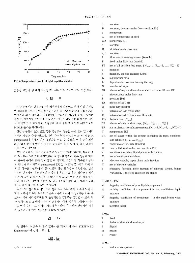
Ç�� ?@' 8� J� Fig. 6' �¸?É$. Fig. 7� Ç�� ?
9 �~ 7² Bg [$. �� ~Ü^� f��) ̂ '�) �~ =
� Ð� B�>, !��� -ê5) �^� �^9) �~ *�
BC$. wU� !�� �� ã @A' 8�g Nü: Bg �
) ¡��$.
��2� Ç�� @A' #s�~, �~ 7² �� !��' ��:
�> Â2�� iN� ]�: Û�g Ç�� �� ~Ü^: ¡�0 (
Fig. 2. Internal vapor and liquid flow in atmospheric distillation column.
Fig. 3. Diameter of atmospheric distillation column at each tray.
Fig. 4. Temperature profiles of atmospheric distillation column.
Table 6. Optimal solutions for light naphtha stabilizer
Design variable[106 kcal/h] Optimal case Base case Case I Case II
Objective function 3.60166 3.7477 3.6284 3.6774Feed tray 14 17 15 16
Fig. 5. Internal vapor and liquid flow in light naphtha stabilizer.
Fig. 6. Diameter of light naphtha stabilizer at each tray.
���� �39� �1� 2001� 2�
������� �� �� 7
}
ser
ry
r
#ü: BÍ$. æ ? ¤¥: n�\< æ ®�~ :* ( #É$.
5. �
ì ý<'�) ��/V�� iNW_ *p2� RS �� ���
C 150,000 BPSD XY ��/V�� � �ô /Væ� @c �õ¸
Ç�� iN ��^: ¡��Í$. /Væ 'k> �J :�)
1� R ��_ <�� 8ã5" #)D, 'k> �J i�� �~
� �N³( W��" /Væ' 8� (�N Yþ: Pÿ2��
MINLP <� ¦��Í$.
�ô /Væ �~ 7² �� !��' ��: �> Â) Bf'�
iN� ]�: (Ä�Í26, �' wU iN ��^� q;� lÀ,
pumparound lÀ iN a3�: }: ( #É$. �E F� iN
� ]�: Û�g }sM ¡�) /Væ iN W_ � iN a3'
?cN2� �g�$.
�� �� ��/V�� �� ~Ü^� 33̂ �É)í, iN� ¡
� ��^� 34̂ 2� _�5É$. iN�% @A) �ì @A' J�
g q;� lÀ: 15% �~ :* ( #26, "� Ý Ï( �Ú�
� �) �* � Z pumparound lÀ: Ð 37% /�\< �' 8
� Ý Ï( �Ú�� � [$. �� �ô /Væ� ça�>� @c
�õ¸ Ç��' 8� iN� Û�g �~ 7² �� !��' ��
: �> Â) iN ��^: ¡�0 ( #É26 �) �ì W_\ G
l% ��^' J�g /Væ � Ç�� ? �� � �� ¤¥:
n�\< æ ®� :* ( #É$.
ì �¦ ¡�� �¸¹ DE F� ��/V�� W_' #s (
�N Yþ' �ù� iN� �·: Gl³2�� iNW_ �, (
#26 �' wU ��Jl � a3Jl: �ñ97 mn0 ( #$. L
= v�5" #) Å>£s0 \�'� &� @yz d� f�g
�~ �E F� \~) _± >±5s� �6 � f� ��_E �_
���¦� =A De?� 12� G�%$.
� �
ì �¦ (Ä: f�g �¦J >��g �f STEPIE LG
EngineeringG' nG #Õ£$.
����
a, A : constant
b : constant
B : constant, bottoms molar flow rate [kmol/h]
c : component
C : set of components in feed
CD : condenser, {1}
d : constant
D : distillate molar flow rate
e, E : constant
f : flow rate of entering stream [kmol/h]
F : feed molar flow rate [kmol/h]
FT : set of all possible feed trays, { }
g : function
h : function, specific enthalpy [J/mol]
K : equilibrium ratio
L : liquid molar flow rate leaving the stage
N : number of trays
NP : the set of trays within column which excludes PA and FT
p : side product molar flow rate
P : pressure [Pa]
PA : the set of SP∪SR
Q : heat duty [kcal/h]
r : internal or side reflux ratio
R : internal or side reflux molar flow rate
RB : bottom tray, {Nmax}
SP : the set of side product trays, { }
SR : theset of returnside refluxstream trays, {
T : temperature [K]
TR : set of stages within the column including the trays, conden
and reboiler, {1, 2, …, Nmax}
V : vapor molar flow rate [kmol/h]
W : side withdrawal molar flow rate [kmol/h]
x : continuous variable, liquid phase mole fraction
X : set of continuous variables
y : discrete variable, vapor phase mole fraction
Y : set of discrete variables
z : objective function, mole fraction of entering stream, bina
variable(1, if the feed enters on the stage)
���� ��
: fugacity coefficient of pure liquid component i
: activity coefficient of component i in the equilibrium liquid
mixture
: fugacity coefficient of component i in the equilibrium vapo
mixture
ω : acentric factor
���
f : feed
k : index of side withdrawal trays
l : liquid
st : steam
v : vapor
���
i : index of components
Nmax 1– Nmax 2– … N, SPkmax 1–, ,
NSP1 NSP
2 … NSPkmax, , ,
NSP1 1– NSP
2 1– … NSPkmax 1–, , ,
φil
γi
φ̂iv
Fig. 7. Temperature profile of light naphtha stabilizer.
HWAHAK KONGHAK Vol. 39, No. 1, February, 2001
8 �������������� �
),
/
ego,
tic
4).
am
j : index of stages
k : index of side withdrawal trays
con : condenser
max : maximum
r : reduced property
reb : reboiler
st : steam
����
1. Uhl, W. C.: in W. F. Bland and R. L. Davidson(Eds), “Petroleum
Processing Handbook: Section 1. Introduction,” McGraw-Hill, New York
(1967).
2. Butler, G. D., Knight, L. L. and Peabody, G. E.: “The World Oil
Market: International Energy Outlook,” Energy Information Admini-
stration, Washington D.C.(1997).
3. Korea Petroleum Association: “The Petroleum Industry in Korea,” Seoul
Korea(1997).
4. Douglas, J. M.: “Conceptual Design of Chemical Processes,” McGraw-
Hill, New York(1988).
5. Liebmann, K., Dhole, V. R. and Jobson, M.: Trans IChemE, 76, Part
A, March, 335(1998).
6. Edgar, T. F. and Himmelblau, D. M.: “Optimization of Chemical
Processes,” McGraw-Hill, New York(1988).
7. Seo, J. W., Kim, S. J., Kim, K. H., Oh, M. and Lee, T. H.: HWA-
HAKKONGHAK, following paper in this issue.
8. Badhwar, R. K.: Chem. Eng. Prog., 66(3), March(1970).
9. Nelson, W. L.: “Petroleum Refinery Engineering,” 4th ed., McGraw-
Hill, New York(1958).
10. Packie, J. W.: AIChE Trans, 27, 51(1941).
11. Watkins, R. N.: “Petroleum Refinery Distillation,” Gulf Publishing Com-
pany, Houston(1973).
12. Srygley, J. M. and Holland, C. D.: AIChE J., 11(4), July, 695(1965).
13. Sargent, R. W. H. and Gaminibandara, K.: in L. D. W. Dixon(Ed
“Optimization in Action: Optimum Design of Plate Distillation Col-
umns,” Academic Press, New York(1976).
14. Viswanathan, J. and Grossmann, I. E.: Ind. Eng. Chem. Res., 32, 2942
(1993).
15. Seo, J. W., Kim, S. J., Kim, K. H., Oh, M. and Lee, T. H.: ASME
JSME Joint Pressure Vessels and Piping Conference, San Di
California, July 26-30, PVP-Vol. 363, 177(1998).
16. Biegler, L. T., Grossmann, E. I. and Westerberg, A. W.: “Systema
Methods of Chemical Process Design,” Prentice Hall(1997).
17. Kocis, G. R. and Grossmann, I. E.: Ind. Eng. Chem. Res., 26(9), 1869
(1987).
18. Mei, D.: M.Sc Dissertation, Imperial College, London(1995).
19. Land, A. H. and Doig, A. G.: Econometrica, 28, 497(1960).
20. Dakin, R. J.: Computer Journal, 8, 250(1965).
21. Benders, J. F.: Numer. Math., 4, 238(1962).
22. Geoffrion, A. M.: J. of Optimization Theory and Applications, 10(4),
237(1972).
23. Duran, M. A. and Grossmann, I. E.: Math Programming, 36, 307(1986).
24. Viswanathan, J. and Grossmann, I. E.: Computers and Chemical Engi-
neering, 14(7), 769(1990).
25. Brooke, A., Kendrick, D. and Meeraus, A.: “GAMS: A User’s Guide,” Boyd
& Fraser Publishing Company, Danvers, MA(1992).
26. Golden, S. W.: Hydrocarbon Technology International, Autumn(199
27. Grayson, H. G. and Streed, C. W.: 6th World Congress, Frankfurt
Main, June, 19(1963).
28. Chao, K. C. and Seader, J. D.: AlChE J., 7(4), 598(1961).
29. Simulation Science: “PRO/II: Keyword Input Manual,” March(1996).
���� �39� �1� 2001� 2�


![HWAHAK KONGHAK - CHERIC · The rejection data allow us to confirm this phenomenon, meaning ... < *+ v L cJ [4,5]. l / s \ ... Experimental setup for measurements of both critical](https://img.dokumen.tips/doc/110x75/5f301645fb0c147d320cf8eb/hwahak-konghak-cheric-the-rejection-data-allow-us-to-confirm-this-phenomenon.jpg)


![[XLS] · Web view2001 2 2003 4 2004 1 2006 1 1995 1 1990 1993 1998 1999 1999 1999 1999 2000 2000 2000 2000 2000 2001 2001 2001 2001 2001 2001 2001 2001 2001 2001 2001 2001 2001 2002](https://img.dokumen.tips/doc/110x75/5bdc2d6f09d3f2bc1c8d6ace/xls-web-view2001-2-2003-4-2004-1-2006-1-1995-1-1990-1993-1998-1999-1999-1999.jpg)