Embed Size (px)
Citation preview
AMS – Victorian Electricity Transmission Network Earth Grids
Document number AMS 10-60
Issue number 9
Status Approved
Approver J. Dyer
Date of approval 17/09/2015
AusNet Services AMS 10-60 Earth Grids
ISSUE 9 17/09/2015 2 / 12 UNCONTROLLED WHEN PRINTED
ISSUE/AMENDMENT STATUS
Issue Number Date Description Author Approved by
5 22/11/06 Editorial review. G Lukies D Postlethwaite
G Towns
7 17/03/07 Editorial review. G Lukies D Postlethwaite
G Towns
8 12/11/12 Revised Structure and General update. P Seneviratne P Yeung C Rabbitte
D Postlethwaite
9 17/09/15 Editorial Review D Platt B Li T Gowland S Sridhar A Shah A Bugheanu
J Dyer
Disclaimer This document belongs to AusNet Services and may or may not contain all available information on the subject matter this document purports to address. The information contained in this document is subject to review and AusNet Services may amend this document at any time. Amendments will be indicated in the Amendment Table, but AusNet Services does not undertake to keep this document up to date. To the maximum extent permitted by law, AusNet Services makes no representation or warranty (express or implied) as to the accuracy, reliability, or completeness of the information contained in this document, or its suitability for any intended purpose. AusNet Services (which, for the purposes of this disclaimer, includes all of its related bodies corporate, its officers, employees, contractors, agents and consultants, and those of its related bodies corporate) shall have no liability for any loss or damage (be it direct or indirect, including liability by reason of negligence or negligent misstatement) for any statements, opinions, information or matter (expressed or implied) arising out of, contained in, or derived from, or for any omissions from, the information in this document.
Contact This document is the responsibility of the Asset Management division of AusNet Services. Please contact the indicated owner of the document with any inquiries. John Dyer AusNet Services Level 31, 2 Southbank Boulevard Melbourne Victoria 3006 Ph: (03) 9695 6000
AusNet Services AMS 10-60 Earth Grids
ISSUE 9 17/09/2015 3 / 12 UNCONTROLLED WHEN PRINTED
Table of Contents
1 Executive Summary ..................................................................................................................... 4 2 Introduction .................................................................................................................................. 5 2.1 Purpose ....................................................................................................................................................... 5 2.2 Scope ........................................................................................................................................................... 5 2.3 References .................................................................................................................................................. 5 3 Asset Summary ............................................................................................................................ 6 3.1 Installed Assets ........................................................................................................................................... 6 3.2 Age Profile ................................................................................................................................................... 7 3.3 Condition ...................................................................................................................................................... 8 3.4 Principal Aspects ......................................................................................................................................... 9 3.5 Inspection and Monitoring......................................................................................................................... 11 3.6 Investment Drivers .................................................................................................................................... 11 4 Strategies .................................................................................................................................... 12
AusNet Services AMS 10-60 Earth Grids
ISSUE 9 17/09/2015 4 / 12 UNCONTROLLED WHEN PRINTED
1 Executive Summary
This document defines the asset management strategies for earthing systems of AusNet Services’ terminal stations and transmission line towers. Earthing systems are installed to:
• ensure safety of personnel and the public; • form low impedance discharge path for earth fault currents and transient surges to protect HV
and LV electrical installations; • ensure correct operation of electrical protection, control and communication systems; • ensure appropriate electrical insulation coordination; and • maintain network reliability.
Earthing systems consist of buried main earth grid electrodes and earthing conductors that are connected to equipment or other infrastructure from main earth grid electrodes within terminal stations. The majority of main earth grid electrodes were installed when the terminal stations were originally established. Since then, they have been enhanced and/or expanded as part of installation of new plant or extension of existing electrical installations. The condition of the earth grid electrodes is generally good. The condition of some station overhead earth wires is showing a level of deterioration due to surface corrosion, and is monitored during inspection. For transmission lines, overhead earth wires were also installed at the same time that the transmission lines were constructed. Some original overhead earth wires have been replaced by optical fibre ground wire as part of augmentation of protection and communication system. Overhead earth wires for transmission lines are covered in AMS 10-79 – Transmission Line Conductors. Key asset management strategies are summarised as follows:
• Complete the earthing system condition monitoring program for station earth grids. • Undertake analysis of historical results to establish an understanding of the capability of each earth
grid. • Ensure earth grid step and touch voltage hazard limits for operational and maintenance requirements
are consistent with international limits1, national limits2 and are specified in the AusNet Services Station Design Manual.
• Continue monitoring program for terminal stations main earth grid electrodes and earthing conductors, continue the ongoing monitoring programs.
• For terminal station overhead earth wires, continue to carry out visual inspections at a maximum interval of 2 years and replace deteriorated earth wires and connectors when appropriate.
• Continue the practice of visual inspection and earth continuity tests on representative critical earthing joints/connectors and sample main earth grid conductors during major terminal station projects.
• Continue to test earthing performance, and to analyse results to determine if augmentation and/or enhancement works are required based on risk assessment.
1 International limits include IEC 61936-1, IEC 60479.1 and IEEE 80. 2 National limits include AS 2067, AS 7000 and AS60479.
AusNet Services AMS 10-60 Earth Grids
ISSUE 9 17/09/2015 5 / 12 UNCONTROLLED WHEN PRINTED
2 Introduction
2.1 Purpose
The purpose of this document is to define the asset management strategies for earthing systems of AusNet Services’ terminal stations earth grids and transmission line towers. This document is intended to assist personnel involved in managing the assets, meeting regulatory obligations and informing other stakeholders by:
• Presenting an overview of the station earth grids and transmission line tower earthing; • Managing business and network risks presented by station earth grids and transmission line
tower earth electrodes efficiently and ensuring that these risks are kept within the limits of safety;
• Achieving supply reliability targets taking into account risk, costs and customer expectations; and
• Ensuring the effective and consistent asset management activities relating to station earth grids and transmission line tower earthing throughout their life-cycle.
2.2 Scope
This asset management strategy applies to all terminal station earth grids and transmission line tower earthing systems that are associated with the Victorian electricity transmission network. The strategies in this document are limited to maintaining installed capability in terms of asset performance and rating. Improvements in quality or capacity are not included in the scope of this document.
2.3 References
This asset management strategy forms part of a suite of documentation that supports the management of AusNet Services’ assets, which include the following:
AMS 01-01 Asset Management System – Overview AMS 10-01 Asset Management Strategy – Transmission Network AMS 10-19 Plant and Equipment Maintenance AMS 10-143 Terminal Station Earth Grid Management Review
AusNet Services AMS 10-60 Earth Grids
ISSUE 9 17/09/2015 6 / 12 UNCONTROLLED WHEN PRINTED
3 Asset Summary
Terminal station earth grids and transmission line tower earth electrodes are designed and constructed to:
• ensure safety of personnel and the public; • provide a low impedance path for fault currents and transient surges to protect electrical
installations; and • ensure correct operation of the electrical protection, control and communication schemes.
3.1 Installed Assets
3.1.1 Terminal Stations and Communications Sites
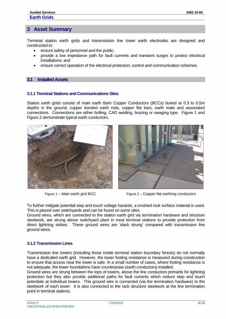
Station earth grids consist of main earth Bare Copper Conductors (BCCs) buried at 0.3 to 0.5m depths in the ground, copper bonded earth rods, copper flat bars, earth mats and associated connections. Connections are either bolting, CAD welding, brazing or swaging type. Figure 1 and Figure 2 demonstrate typical earth conductors.
Figure 1 – Main earth grid BCC
Figure 2 – Copper flat earthing conductors
To further mitigate potential step and touch voltage hazards, a crushed rock surface material is used. This is placed over switchyards and can be found on some sites. Ground wires, which are connected to the station earth grid via termination hardware and structure steelwork, are strung above switchyard plant in most terminal stations to provide protection from direct lightning strikes. These ground wires are ’slack strung’ compared with transmission line ground wires.
3.1.2 Transmission Lines
Transmission line towers (including those inside terminal station boundary fences) do not normally have a dedicated earth grid. However, the tower footing resistance is measured during construction to ensure that access near the tower is safe. In a small number of cases, where footing resistance is not adequate, the tower foundations have counterpoise (earth conductors) installed. Ground wires are strung between the tops of towers, above the line conductors primarily for lightning protection but they also provide additional paths for fault currents which reduce step and touch potentials at individual towers. This ground wire is connected (via the termination hardware) to the steelwork of each tower. It is also connected to the rack structure steelwork at the line termination point in terminal stations.
AusNet Services AMS 10-60 Earth Grids
ISSUE 9 17/09/2015 7 / 12 UNCONTROLLED WHEN PRINTED
To provide increased safety for the public, activities such as the building of structures, swimming pools, fences and other conducting items on line easements are restricted. Insulating panels are often installed in metallic fences, located in the vicinity of towers. The aim of these measures is to limit voltage transfer to remote sites and to limit public exposure to conducting mediums in the event of an earth fault. Refer to the AMS 10-65 - Line Easements for further information.
3.2 Age Profile
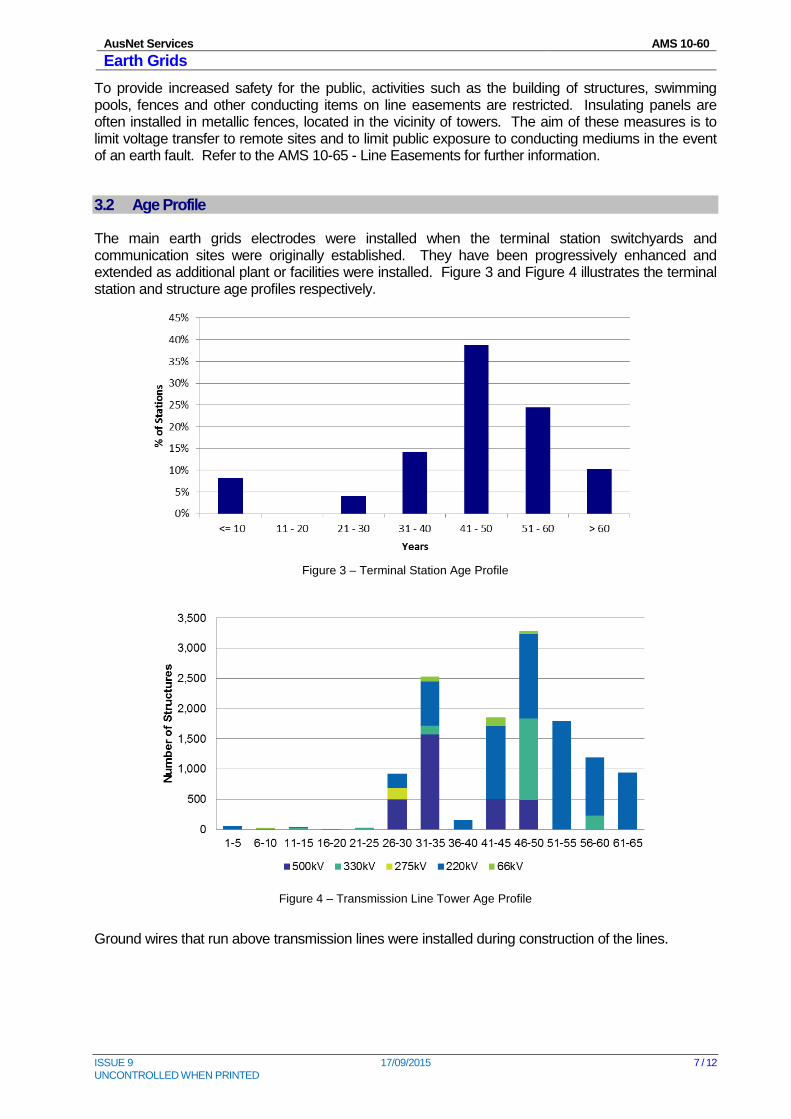
The main earth grids electrodes were installed when the terminal station switchyards and communication sites were originally established. They have been progressively enhanced and extended as additional plant or facilities were installed. Figure 3 and Figure 4 illustrates the terminal station and structure age profiles respectively.
Figure 3 – Terminal Station Age Profile
Figure 4 – Transmission Line Tower Age Profile
Ground wires that run above transmission lines were installed during construction of the lines.
AusNet Services AMS 10-60 Earth Grids
ISSUE 9 17/09/2015 8 / 12 UNCONTROLLED WHEN PRINTED
3.3 Condition
The physical conditions of the below ground earth grids are generally good. This is due to: • Copper is not adversely affected by the majority of soils; • Stations generally have effective surface drainage systems; • Comparatively non-aggressive soils and backfill materials are used in stations; and • Long life materials with high-reliability joints are used.
However, the following concerns are raised and are to be addressed in ongoing inspection program.
• Potential mechanical damage due to traffic impact; and • Stray AC current resulting in acceleration of corrosion.
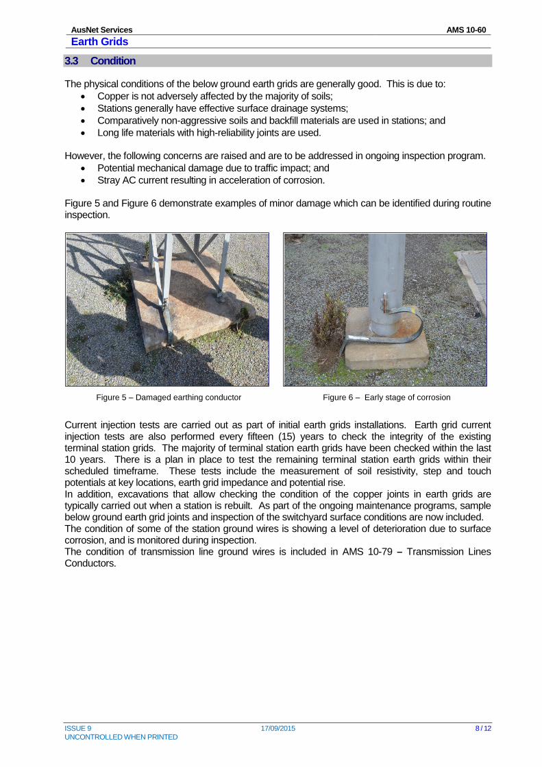
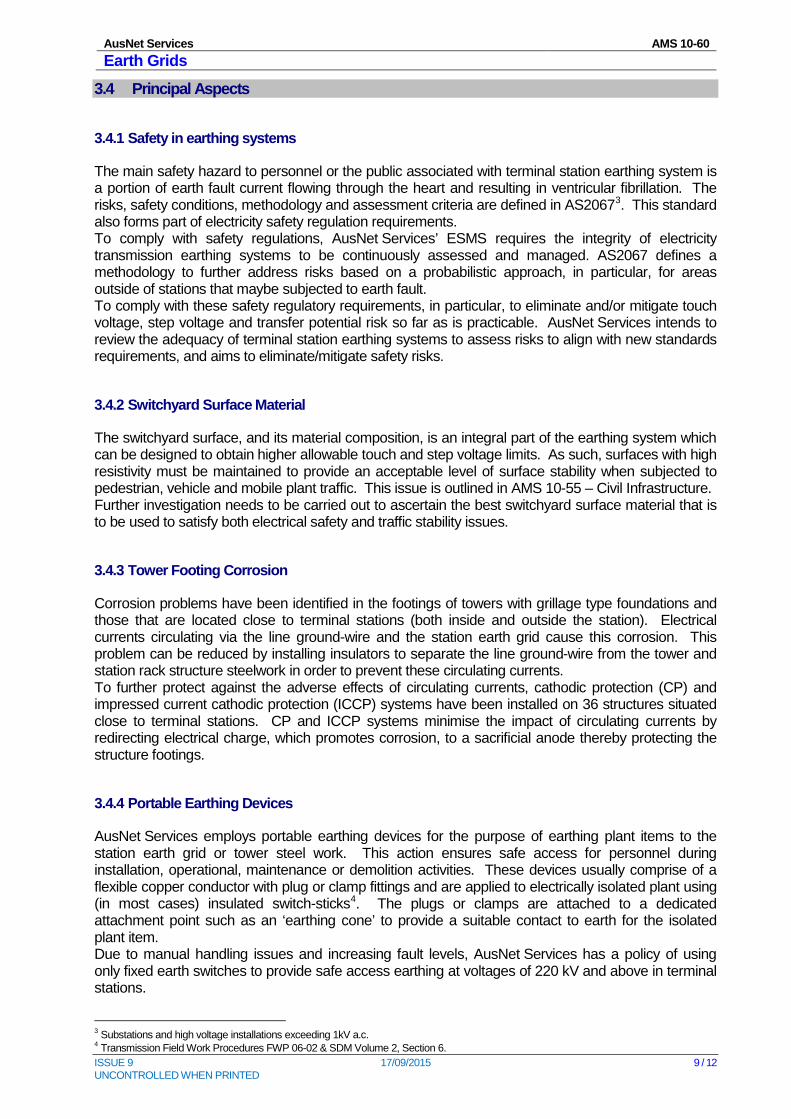
Figure 5 and Figure 6 demonstrate examples of minor damage which can be identified during routine inspection.
Figure 5 – Damaged earthing conductor
Figure 6 – Early stage of corrosion
Current injection tests are carried out as part of initial earth grids installations. Earth grid current injection tests are also performed every fifteen (15) years to check the integrity of the existing terminal station grids. The majority of terminal station earth grids have been checked within the last 10 years. There is a plan in place to test the remaining terminal station earth grids within their scheduled timeframe. These tests include the measurement of soil resistivity, step and touch potentials at key locations, earth grid impedance and potential rise. In addition, excavations that allow checking the condition of the copper joints in earth grids are typically carried out when a station is rebuilt. As part of the ongoing maintenance programs, sample below ground earth grid joints and inspection of the switchyard surface conditions are now included. The condition of some of the station ground wires is showing a level of deterioration due to surface corrosion, and is monitored during inspection. The condition of transmission line ground wires is included in AMS 10-79 – Transmission Lines Conductors.
AusNet Services AMS 10-60 Earth Grids
ISSUE 9 17/09/2015 9 / 12 UNCONTROLLED WHEN PRINTED
3.4 Principal Aspects
3.4.1 Safety in earthing systems
The main safety hazard to personnel or the public associated with terminal station earthing system is a portion of earth fault current flowing through the heart and resulting in ventricular fibrillation. The risks, safety conditions, methodology and assessment criteria are defined in AS20673. This standard also forms part of electricity safety regulation requirements. To comply with safety regulations, AusNet Services’ ESMS requires the integrity of electricity transmission earthing systems to be continuously assessed and managed. AS2067 defines a methodology to further address risks based on a probabilistic approach, in particular, for areas outside of stations that maybe subjected to earth fault. To comply with these safety regulatory requirements, in particular, to eliminate and/or mitigate touch voltage, step voltage and transfer potential risk so far as is practicable. AusNet Services intends to review the adequacy of terminal station earthing systems to assess risks to align with new standards requirements, and aims to eliminate/mitigate safety risks.
3.4.2 Switchyard Surface Material
The switchyard surface, and its material composition, is an integral part of the earthing system which can be designed to obtain higher allowable touch and step voltage limits. As such, surfaces with high resistivity must be maintained to provide an acceptable level of surface stability when subjected to pedestrian, vehicle and mobile plant traffic. This issue is outlined in AMS 10-55 – Civil Infrastructure. Further investigation needs to be carried out to ascertain the best switchyard surface material that is to be used to satisfy both electrical safety and traffic stability issues.
3.4.3 Tower Footing Corrosion
Corrosion problems have been identified in the footings of towers with grillage type foundations and those that are located close to terminal stations (both inside and outside the station). Electrical currents circulating via the line ground-wire and the station earth grid cause this corrosion. This problem can be reduced by installing insulators to separate the line ground-wire from the tower and station rack structure steelwork in order to prevent these circulating currents. To further protect against the adverse effects of circulating currents, cathodic protection (CP) and impressed current cathodic protection (ICCP) systems have been installed on 36 structures situated close to terminal stations. CP and ICCP systems minimise the impact of circulating currents by redirecting electrical charge, which promotes corrosion, to a sacrificial anode thereby protecting the structure footings.
3.4.4 Portable Earthing Devices
AusNet Services employs portable earthing devices for the purpose of earthing plant items to the station earth grid or tower steel work. This action ensures safe access for personnel during installation, operational, maintenance or demolition activities. These devices usually comprise of a flexible copper conductor with plug or clamp fittings and are applied to electrically isolated plant using (in most cases) insulated switch-sticks4. The plugs or clamps are attached to a dedicated attachment point such as an ‘earthing cone’ to provide a suitable contact to earth for the isolated plant item. Due to manual handling issues and increasing fault levels, AusNet Services has a policy of using only fixed earth switches to provide safe access earthing at voltages of 220 kV and above in terminal stations.
3 Substations and high voltage installations exceeding 1kV a.c. 4 Transmission Field Work Procedures FWP 06-02 & SDM Volume 2, Section 6.
AusNet Services AMS 10-60 Earth Grids
ISSUE 9 17/09/2015 10 / 12 UNCONTROLLED WHEN PRINTED
AusNet Services AMS 10-60 Earth Grids
ISSUE 9 17/09/2015 11 / 12 UNCONTROLLED WHEN PRINTED
3.5 Inspection and Monitoring
Performance of the earthing systems within the stations should be monitored to ensure that the systems operate effectively. In addition to above ground visual inspections, there are two levels of ongoing monitoring programs for terminal stations main earth grid electrodes and earthing conductors. Level 1 monitoring tests include earth continuity test on earthing connections of the following assets and are performed every three years5:
• Power transformer and neutral points; • Neutral earthing reactors/resistors; • Operation earth mat on manually operated earth switches; • CTs and VTs; • Lighting masts; and • Surge arresters.
Level 2 monitoring tests are performed every 15 years involving:
• Current injection test on grid impedance; • Step and touch voltages on critical items; • Earth potential rise contours; and • Transferred potentials.
3.6 Investment Drivers
The main investment driver is the requirement to ensure the adequacy and integrity of existing earth grids from the viewpoint of electrical safety and plant operation limit. This is expected to be achieved by continuously assessing and managing residual earthing risks, ongoing earth grid condition monitoring program, and inspection of the condition of foundations for at-risk transmission line towers that are located close to terminal stations.
5 Dependant on severity of corrosion and duty.
AusNet Services AMS 10-60 Earth Grids
ISSUE 9 17/09/2015 12 / 12 UNCONTROLLED WHEN PRINTED
4 Strategies
High level strategies to be adopted for prudent and efficient management of the earthing systems of terminal stations and transmission line towers are:
• Complete the earthing system condition monitoring program for station earth grids. • Undertake analysis of historical results to establish an understanding of the capability of each earth
grid. • Ensure earth grid step and touch voltage hazard limits for operational and maintenance requirements
are consistent with international limits6, national limits7 and are specified in the AusNet Services Station Design Manual.
• Continue monitoring program for terminal stations main earth grid electrodes and earthing conductors, continue the ongoing monitoring program which include the following:
o Carry out Level 1 monitoring tests on station earth grids at maximum interval of 3 years if subjected to severity of corrosion and duty on conductors.
o Carry out Level 2 monitoring tests on station earth grids at maximum interval of 15 years depending on risk assessment.
o Carry out above ground visual inspections with maximum interval of 2 years. • For terminal station overhead earth wires, continue to carry out visual inspections at a maximum
interval of 2 years and replace deteriorated earth wires and connectors when appropriate. • Continue the practice of visual inspection and earth continuity tests on representative critical earthing
joints/connectors and sample main earth grid conductors during major terminal station projects. • Continue to test earthing performance, and to analyse results to determine if augmentation and/or
enhancement works are required based on risk assessment.
6 International limits include IEC 61936-1, IEC 60479.1 and IEEE 80. 7 National limits include AS 2067, AS 7000 and AS60479.