Embed Size (px)
Citation preview

Ammonia Injection and Mixing Systems 101
Kanthan Rajendran, P.E.Airflow Sciences Corporation
2018 NOx-Combustion-CCR Round TableFebruary 19, 2018
St Louis, MO

Agenda● Intro● Coal Fired SCR● Gas Turbine SCR
2

NOx Control
● Nitrogen oxides, also known as NOx, are important air pollutants by themselves; also react in the atmosphere to form ozone (O3) and acid rain
● NOx is formed in the boiler at temperatures greater than 3600ºF● 95% of NOx in the flue gas is initially in the form of NO, rest is NO2 ● Once in the atmosphere, most NOx is converted into NO2 form● Typical SCR systems can achieve NOx removal efficiencies over 90%
3

Selective Catalytic ReductionSelective catalytic reduction (SCR) is a chemical process of using a reductant like ammonia to convert NOx into diatomic nitrogen (N2) and water (H2O), with the aid of a catalyst.
4NO + 4NH3 + O2 → 4N2 + 6H2O
2NO2 + 4NH3 + O2 → 3N2 + 6H2O
NO + NO2 + 2NH3 → 2N2 + 3H2O
Ammonia has to react with NOx at the molecular level.
4
NOx
NH3
SCR N2 + H2O

What Do You Mix for SCR?● Ammonia● NOx
○ Mixing may be needed if incoming NOx distribution is not uniform
● Ammonia-to-NOx ratio○ Getting the right amount of ammonia for the
amount of NOx present
● Temperature○ SCR reactions occur optimally within a specific
temperature range
5
NOx Removal Efficiency vs Temperature

Why Do You Mix?
Large Scale Mixing Local Mixing
6
Normalized Concentration
Ammonia must be dispersed and mixed thoroughly with the flue gas to maximize contact between the reactants. NOx removal rate highly dependent on level of mixing.

How Do You Mix?● Control the flow streams at the
injection location○ Multi-point injection○ Nozzle design○ Diffusion + turbulence
● Churn up the flow after the injection
○ Induce high turbulence○ Create shear forces○ Generate swirl or vortices
7

Where Do You Mix?For Coal Fired SCR:
● NOx & temperature ○ upstream AIG○ “Premixer”
● Ammonia○ at or after injection location
8

Where Do You Mix?For Gas Turbine SCR:
● NOx is typically uniform● Temperature
○ upstream of CO catalyst○ For systems with tempering air or
duct burners
● Ammonia○ at or after AIG
9

Coal Fired SCR Performance GoalsTypical performance goals compete with each other:
● Uniform ammonia-to-NOx ratio● Uniform velocity at AIG and catalyst● Vertical flow entering catalyst● Uniform temperature at catalyst● Capture LPA with screen/baffles● Minimize pluggage potential● Minimize pressure loss● Minimize erosion potential
10

Ammonia-to-NOx Ratio● Ammonia-to-NOx ratio at the catalyst inlet plane should be “uniform”● Allows optimal NOx reduction with minimum ammonia slip● Typical goal is %RMS < 5% or deviation within +/-5% of mean● Can be highly influenced by velocity patterns
11
PoorDistribution
BetterDistribution

NOx Stratification● NOx is not necessarily uniform at the boiler exit; it is a function of
○ Boiler design○ Burner air flow balance○ Coal pipe balance○ Mills out-of-service
● Solutions○ Mix the NOx prior to the NH3 injection – “Pre-mixer”○ Mix the NOx and the NH3○ Tune the NH3 to the NOx profile
■ Consistency over load range important
12
Example of NOx Profile at Economizer Outlet

Ammonia Injection● Two basic strategies are used for ammonia injection in SCRs
○ Dense grid of injection pipes○ Coarse grid of injection pipes with mixers
13

Dense Grid Ammonia Injection● Many injection lances with multiple nozzles per lance
○ Depending on SCR size, could have 50-100 lances per reactor○ Typically 6-10 nozzles per lance○ Hundreds of discrete injection points
● Often no mixer or only a “local” mixer● Lances grouped into zones for tuning● Benefits of dense grid injection
○ More tunable for maximum NOx reduction○ No negative influence on velocity or flyash distribution at catalyst○ Lower pressure drop
14
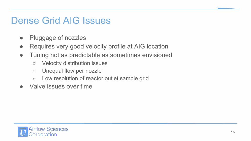
Dense Grid AIG Issues● Pluggage of nozzles● Requires very good velocity profile at AIG location● Tuning not as predictable as sometimes envisioned
○ Velocity distribution issues○ Unequal flow per nozzle○ Low resolution of reactor outlet sample grid
● Valve issues over time
15

Coarse Grid Ammonia Injection● Fewer injection lances compared to dense grid by factor of 5-10
○ Depending on SCR size, could have 5, 10, 20 lances per reactor○ Some systems have just 1 injection point per lance○ Others have multiple nozzles per lance (2 to 10)
● Lances located immediately upstream of a static mixer● Often multiple stages of static mixers● Benefits of coarse grid injection
○ Fewer nozzles and larger openings less prone to pluggage○ Mixing and high turbulence reduces sensitivity of gradients
■ Does not need as much tuning?■ More consistent performance over the load range
16

Coarse Grid AIG Issues● Higher pressure loss● Duct wall and internal
structure erosion● Ash accumulation on
mixers● Tuning not as
straightforward due to purposeful creation of turbulence
17

Vaporized Ammonia Injection vs Direct Injection● Vaporized Ammonia Injection
○ utilizes vaporizer skid to get ammonia into gaseous form prior to injection○ need to ensure ammonia properly vaporized and mixed with dilution air○ more common but higher capital cost
● Direct Injection ○ inject aqueous ammonia directly in liquid form without dilution air or vaporization○ relies on heat from flue gas for vaporization○ requires special spray nozzles to insure proper vaporization and mixing○ concern about liquid ammonia impingement on walls, mixer
18

Types of Mixers● Shear Mixers● Swirl-Shear Mixers● Vortex Mixers
19

Shear Mixers
20

Swirl-Shear Mixers
21

Vortex Mixers
22

Vortex Mixers
23

Vortex Mixers
24

Mixer IssuesErosion
25

Mixer IssuesPressure Drop
26

Summary – Coal Fired SCR● NH3, NOx, and temperature distributions are key players in SCR
performance● Pre-mixer often used for NOx and temperature at boiler outlet● Dense Grid injection generally no mixer or “local” mixer● Coarse Grid injection will have 1 or more high turbulence mixer layers● Ammonia injection and mixer design involves many competing criteria
which must be understood and optimized
27

Gas Turbine SCR● Gas turbine systems come in many sizes and flavors
○ Simple cycle○ Combined cycle / HRSG○ With / without CO catalyst○ With / without tempering air
28

Gas Turbine SCR Performance GoalsTypical performance goals compete with each other:
● Uniform ammonia-to-NOx ratio● Uniform velocity at AIG and catalyst● Uniform velocity at CO catalyst● CO catalyst influence on SCR● Uniform temperature at catalyst● Minimize pressure loss
29

Flow Distribution in Gas Turbine SCR● Gas Flow Through System
○ Uniform velocity profile (15% RMS or better) at■ CO/NOx/Dual Action Catalyst■ AIG■ Tube banks
● Not easy given that the inlet condition resembles a tornado
● Requires intricate design of flow devices○ Baffles○ Straighteners○ Perforated plates
30
Flow Streamlines in a HRSG CFD model

Ammonia Injection in Gas Turbine SCR● Design considerations for ammonia injection
○ The key factor in deNOx performance and ammonia slip○ Goal is uniform concentration (ammonia-to-NOx ratio) at SCR catalyst○ General target is 5% RMS or better○ Optimization requires balance of competing goals
■ Velocity profile at AIG & SCR catalyst■ Pressure drop
○ AIG design is not straightforward■ Residence time for mixing is limited■ Temperature heat up can affect distribution■ Updated design practices have led to advances■ Older systems likely have room for improvement
31

Ammonia Injection Grid● AIG Design:
○ General goal is to inject equal ammonia from each nozzle to within 2% or better
○ Correct sizing of header ID, lance ID, and nozzle diameters is important
○ Need to consider heat transfer from gas side to the internal pipe flow; this can influence the balance between nozzles
○ The presence of tuning valves cannot always fix a poor AIG header/lance design
32
Flow Modeling of AIG header and lances

Ammonia Distribution at SCR● Need to ensure sufficient number of
lances/nozzles to cover the cross section● Depends on residence time to catalyst and
turbulence intensity● Additional mixing may be required
depending on geometry details○ Static mixer after AIG○ Turbulence generators integrated with AIG
● Modeling and testing to guide design
33

AIG Optimization Case Study● HRSG unit struggling with poor
ammonia distribution at the SCR catalyst and high ammonia slip.
● Plant AIG tuning was not successful, could not eliminate high ammonia gradients near walls
● CFD model corroborated field data showing velocity profile at the AIG having large areas of low flow or recirculation, which would allow ammonia to accumulate.
34

AIG Optimization Case Study● CFD model indicates very high ammonia
concentrations near the walls of the unit.● Ammonia RMS of 59% at the SCR catalyst face.
35
Ammonia Distribution RMS of 59% at SCR Catalyst Face

AIG Optimization Case Study● AIG modifications added to improve local mixing
and ammonia distribution● Ammonia RMS improved to 8% at the catalyst face
36
Ammonia Distribution RMS of 8% at SCR Catalyst Face

Summary – Gas Turbine SCR● There are many parameters that affect gas turbine and SCR performance ● AIG design involves many competing criteria which must be understood
and optimized● Residence time is usually quite limited in gas turbine SCR; local mixer
may be necessary● Need optimized design at beginning, and design improvements over time● Cost-effective enhancements are possible to existing systems
37

Questions & Contact Information
Kanthan Rajendran, P.E.
Project Engineer
734-525-0300 x224
www.airflowsciences.com
38