Embed Size (px)
Citation preview

Aluminum Clad Wood Window
Field Mulling and Stacking
Instructions
IMPORTANT: Please read before you begin.
Mulling Stacking
Mulling and Stacking

ii
TABLE OF CONTENTS AND TOOL / MATERIAL REQUIREMENTSSTART PAGE
Stacking & Mulling Notice; Design Pressure Test Rating Concerns . . . . . . . . . . . . . . . . . . . . . . iii
Safety Alert Symbol . . . . . . . . . . . . . . . . . . . . . . . . . . . . . . . . . . . . . . . . . . . . . . . . . . . . . . . . . . . . . iv
Field Mulling and/or Stacking Preparation . . . . . . . . . . . . . . . . . . . . . . . . . . . . . . . . . . . . . . . . . . . 1
Nailing Fin Removal . . . . . . . . . . . . . . . . . . . . . . . . . . . . . . . . . . . . . . . . . . . . . . . . . . . . . . . . . . . . . . 2
Utility Knife, Dead-Blow Hammer, Locking Pliers, Hacksaw, Tin Snips
Open Exterior Accessory Grooves . . . . . . . . . . . . . . . . . . . . . . . . . . . . . . . . . . . . . . . . . . . . . . . . . . 3
Hacksaw, Stiff Bristle Brush
Assemble and Fasten Units – Interior Side Up . . . . . . . . . . . . . . . . . . . . . . . . . . . . . . . . . . . . . . . . 4
Clear Silicone Sealant, Caulking Gun, Clamps, 1" Wide x 3/8" Deep Corrugated Staples, Level,
Straightedge, Hammer, Mull Plates, 7/16" x 1/2" Long Staples or #8 x 1/2" Phillips Pan Head
Sheet Metal Screws, Stapler, Phillips Screwdriver
Interior Mull Cover Application . . . . . . . . . . . . . . . . . . . . . . . . . . . . . . . . . . . . . . . . . . . . . . . . . . . . . .6
Measuring Tape, Hammer, 1-1/2" Long 4D Finishing Nails, Interior Mull Covers, Nail Set,
Crosscut Saw, Drill and Drill Bits
Exterior Mull Cover Application . . . . . . . . . . . . . . . . . . . . . . . . . . . . . . . . . . . . . . . . . . . . . . . . . . . . .7
Measuring Tape, Dead-Blow Hammer, Hacksaw, Exterior Mull Covers, Clear Silicone Sealant,
Caulking Gun, Clean Soft Shop Towels, Denatured Alcohol
Caulk Joints & Apply Sill Gasket . . . . . . . . . . . . . . . . . . . . . . . . . . . . . . . . . . . . . . . . . . . . . . . . . . . 11
Silicone Sealant, Caulking Gun, Sill Gasket
Install Drip Cap . . . . . . . . . . . . . . . . . . . . . . . . . . . . . . . . . . . . . . . . . . . . . . . . . . . . . . . . . . . . . . . . . 12
Measuring Tape, Silicone Sealant, Caulking Gun, 1-Piece Aluminum Drip Cap, #8 x 1/2" Phillips
Pan Head Stainless Steel Sheet Metal Screws or #8 x 1/2" Stainless Steel TEK Tip Screws,
Hacksaw, Phillips Screwdriver
Recommended Finishing Instructions for Vinyl, Aluminum or Wood . . . . . . . . . . . . . . . . . . . . . 13
Products With Synthetic Stucco . . . . . . . . . . . . . . . . . . . . . . . . . . . . . . . . . . . . . . . . . . . . . . . . . . . 14

iii
Aluminum Clad Wood Window
Field Mulling and Stacking Instructions
IMPORTANT: Thoroughly read and follow these instructions. Failure to install as
recommended will void any warranty, expressed or implied. Check building codes for the area in
which the windows are being installed before installation to ensure proper compliance. The
instructions that follow are based on typical frame construction. Specific applications may differ. The
window manufacturer recommends that you consult a qualified installation professional. The window
manufacturer is not responsible for installation.
IMPORTANT: A number of jurisdictions have adopted building code design pressure
requirements that require windows be installed in the same way they were installed for laboratory
testing. To comply with these requirements, we are pleased to supplement the installation instructions
with the following:
Sealant must be applied in all installations. There must be continuous contact with a
generous bead of sealant between the bare sheathing and the window unit’s nailing fin
around the window’s entire perimeter.
The following additional steps must be taken as appropriate.
• Exterior house wrap must be cut and temporarily taped back away from rough openings.
• When sealant is applied to the rough opening it must be applied directly to the building’s
sheathing and NOT the building wrap.
• The nailing fin must contact the sealant continuously along the entire perimeter of the
unit and must fully contact exterior face of the wall around the window’s entire perimeter.
• Exterior housewrap must be trimmed and reapplied over the nailing fin. It must be sealed
to the fin along the entire perimeter with silicone sealant.
Fastening methods must conform to those used to install test units. Consult the fastening
method chart included in the installation instructions for each specific unit.
A shim space, not to exceed 1/4", is required. If a shim space greater than 1/4" exists on the
interior or exterior of the unit, use solid material to fill this space until the maximum 1/4"
shim allowance is achieved.
ADDITIONAL NOTES:
• For any installation that has exposed fasteners, it is recommended to use fasteners made
of 300 series stainless steel. Follow your local codes if they specify a different series of
stainless steel.
• Certain options, accessories and warranty considerations require the unit be installed
using installation clips. The clip install method has not been tested for design pressure
ratings and should not be used where design pressure ratings must be maintained.
Contact your customer service representative for additional assistance.
Stacking, mulling, or combinations of stacking and mulling may have installation restrictions and additional
reinforcement requirements for your area. The window manufacturer recommends that the installer consult
a registered Architect or local Structural Engineer for guidance to ensure the installation meets all codes and
application rules regarding installation of stacked, mulled, or stacked and mulled combinations.
The following instructions are for completing a
tight mull, stack, or mull and stack combination
for aluminum clad wood windows.
Contact your customer service representative for
instructions for other types of mull and mull
stack operations.
To install a combined unit follow the installation
instructions packed with the individual windows.
The installation instructions include details for
specific window types and should be consulted
before installing any mull, stack, or mull stack
combined unit.

iv
The window manufacturer reserves the right, as necessary, to change product specifications, installation procedures, materials,
prices and terms of purchase without notice.
Weight of window and accessories will vary. Use
a reasonable number of people with sufficient
strength to lift, carry and install window unit(s) and
accessories. Always consider site conditions and use
appropriate techniques when installing.
Falling from window opening may
result in serious injury or death. DO
NOT leave openings unattended when
children are present.
Screen will not stop children,
any one or anything from
falling out window.
Keep children and objects
away from open window.
CUT HAZARD*Non-safety Glass.
*May cause serious
injuries if broken.
*Do not install where
tempered safety glass
is required.
Recognize this symbol. This is the Safety-Alert symbol. When you see this symbol be
alert to the potential for personal injury or product damage.

1
The process for mulling or stacking differs from
mulling and stacking. Please follow the proper
steps.
Please observe the following definitions for terms
used in the subsequent instructions:
• Mulling: Joining two or more units together
horizontally (FIGURE 1).
• Stacking: Joining two or more units together
vertically (FIGURE 1).
• Mulling and Stacking: Joining mulled units
with stacked units to form a multi-wide multi-
high unit.
IMPORTANT: When placing units to
be mulled or stacked, make sure the sills or
water weeps on each unit will face towards the
sill (bottom) of the rough opening when the
combined unit is installed.
IMPORTANT: High-quality, exterior,
neutral-cure, clear, silicone sealant (compatible
with wood, aluminum and exterior face of the
wall) is to be used for all procedures in the
following instructions which call for caulking or
sealant.
SAFETY INSTRUCTIONSRead these instructions completely before
beginning procedure.
Wear gloves, safety glasses, goggles oreye shields appropriate to procedure.
Field Mulling and/or Stacking Preparation
MULLING
STA
CK
ING
Improper use of hand and power tools could
result in personal injury and/or product damage.
Follow equipment manufacturers’ instructions for
safe operation. Always wear safety glasses.
FIGURE 1
Place units to be mulled and/or stacked
on a clean flat surface (exterior side up) in
the position that they will be assembled
(FIGURE 1).

2
Nailing Fin Removal
1. Nailing fins must be removed from jambs that
will be attached together (X’s in FIGURE 1).
2. Use a hacksaw or tin snips to make an initial cut
into a fin at a corner (FIGURE 2). Cut straight
inward to the jamb.
3. Score each fin that needs to be removed, next
to the jamb, with a utility knife (FIGURE 3). Score
along the nailing fin’s entire length.
4. Use a dead-blow hammer to create an initial
bend in the scored nailing fin (FIGURE 4).
5. Continue bending the scored fin up and down
with pliers until it breaks off (FIGURE 5).
Follow the above steps until all identified fins are
removed.
X X
XX
X X
XX
FIGURE 1
FIGURE 2
FIGURE 3
FIGURE 4
FIGURE 5

3
For mulling and stacking, the exterior accessory
groove inside corners must be opened (FIGURE
1A) to allow mull covers (FIGURE 1) to go the full
height or width of the assembly.
Four-way corners, as shown in (FIGURES 1 &
1A), must be opened in all directions.
For either a mull only or stack only, the accessory
grooves need to be opened at the outside ends on
both sides of each unit.
1. To open a corner in both directions, use a
hacksaw and start with a vertical cut (FIGURE 2).
Cut across the corner and only as deep as the
bottom of the accessory groove.
2. Make horizontal cuts (FIGURES 3 & 4) to
complete the opening. When the cut is finished,
clean out burrs and shavings with a stiff bristle
brush.
3. To open an accessory groove for a mull or
stack only, make the first cut vertically and in the
same direction as the mull cover will be applied
(FIGURE 5). Cut only as deep as the bottom of
the accessory groove.
4. Finish cutting across the vertical cut (FIGURE
6). When the cut is finished, clean out burrs and
shavings with a stiff bristle brush.
5. After the nailing fins are removed and the
exterior accessory grooves are opened and
cleaned, turn the window units over so the
interior side is up.
IMPORTANT: Ensure the the head
and sill orientation is maintained when the
units are turned over.
Open Exterior Accessory Grooves
FIGURE 2 FIGURE 3
FIGURE 4
FIGURE 5 FIGURE 6
SEPARATEHORIZONTALMULL COVER
FULL-HEIGHTVERTICAL
MULL COVER
FIGURE 11A
4
Assemble And Fasten Units – Interior Side Up
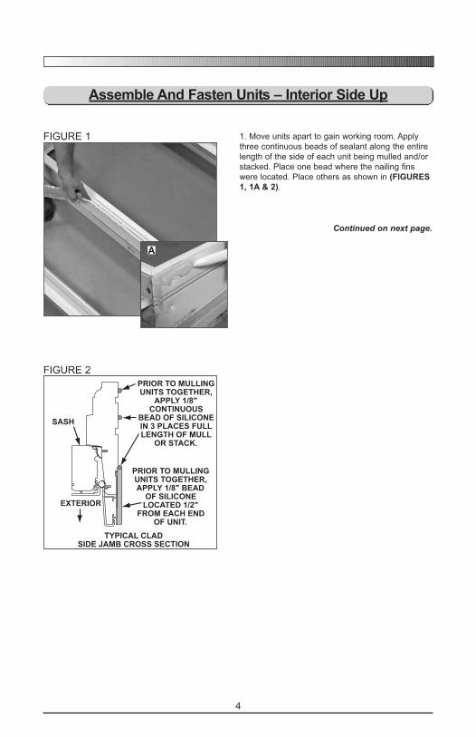
1. Move units apart to gain working room. Apply
three continuous beads of sealant along the entire
length of the side of each unit being mulled and/or
stacked. Place one bead where the nailing fins
were located. Place others as shown in (FIGURES
1, 1A & 2).
Continued on next page.
FIGURE 1
A
FIGURE 2
PRIOR TO MULLINGUNITS TOGETHER,
APPLY 1/8"CONTINUOUS
BEAD OF SILICONEIN 3 PLACES FULLLENGTH OF MULL
OR STACK.
PRIOR TO MULLINGUNITS TOGETHER,APPLY 1/8" BEAD
OF SILICONELOCATED 1/2"
FROM EACH ENDOF UNIT.
EXTERIOR
TYPICAL CLADSIDE JAMB CROSS SECTION
SASH
5
FIGURE 3
FIGURE 4
FIGURE 5
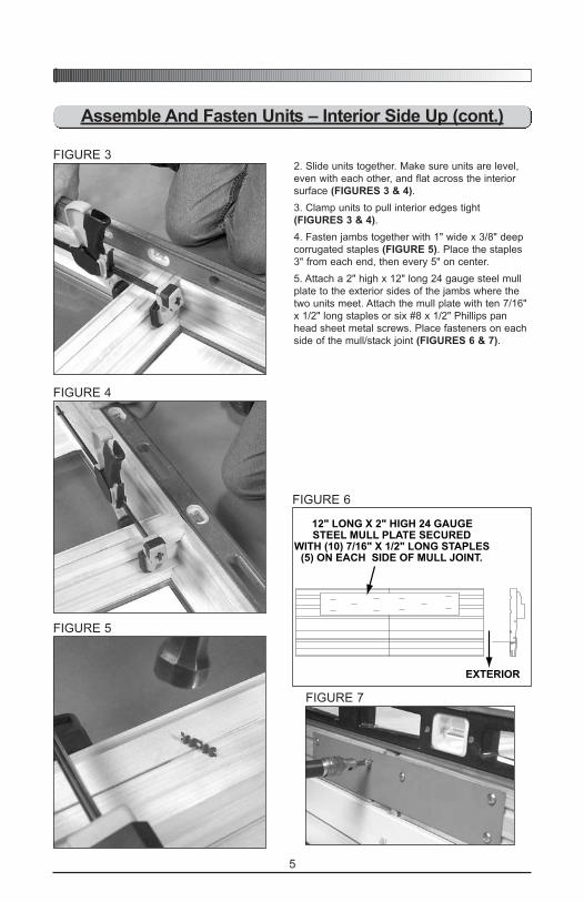
2. Slide units together. Make sure units are level,
even with each other, and flat across the interior
surface (FIGURES 3 & 4).
3. Clamp units to pull interior edges tight
(FIGURES 3 & 4).
4. Fasten jambs together with 1" wide x 3/8" deep
corrugated staples (FIGURE 5). Place the staples
3" from each end, then every 5" on center.
5. Attach a 2" high x 12" long 24 gauge steel mull
plate to the exterior sides of the jambs where the
two units meet. Attach the mull plate with ten 7/16"
x 1/2" long staples or six #8 x 1/2" Phillips pan
head sheet metal screws. Place fasteners on each
side of the mull/stack joint (FIGURES 6 & 7).
12" LONG X 2" HIGH 24 GAUGESTEEL MULL PLATE SECURED
WITH (10) 7/16" X 1/2" LONG STAPLES(5) ON EACH SIDE OF MULL JOINT.
EXTERIOR
FIGURE 6
FIGURE 7
Assemble And Fasten Units – Interior Side Up (cont.)

6
NOTE: If mulling and stacking, install the vertical
mull cover first. Then install the horizontal
covers.
NOTE: To prevent handling damage, interior mull
covers can be applied after window is
installed in the structure.
NOTE: Length of interior mull cover pieces is
dependent on reveal between casing
moulding and jambs.
1. To determine the length of the vertical mull
cover, measure the unit assembly height, jamb to
jamb (FIGURE 1) and subtract reveal x2. Cut the
mull cover to length with a saw.
IMPORTANT: To prevent splitting
or cracking, drill pilot holes in cover before
nailing.
2. Install vertical cover by centering cover on
jambs; center side-to-side and end-to-end. Drill
pilot holes and nail to jambs with 1-1/2" long 4D
finishing nails (FIGURE 3). Set nails below wood
surface with a nail set.
3. Measure for both horizontal covers along jambs,
going from edge of vertical cover to edge of jamb,
and subtract reveal X1 (FIGURE 2). Cut pieces to
length with a saw.
4. Butt horizontal covers to vertical piece, center
top to bottom on adjacent units, drill pilot holes,
and nail in place with 1-1/2" long 4D finishing nails.
Set nails below wood surface with a nail set.
5. Remove clamps.
Improper use of hand or power tools could result in
personal injury and/or product damage. Follow
equipment manufacturers’ instructions for safe
operation. Always wear safety glasses.
Interior Mull Cover Application
FIGURE 1
FIGURE 2
FIGURE 3
7
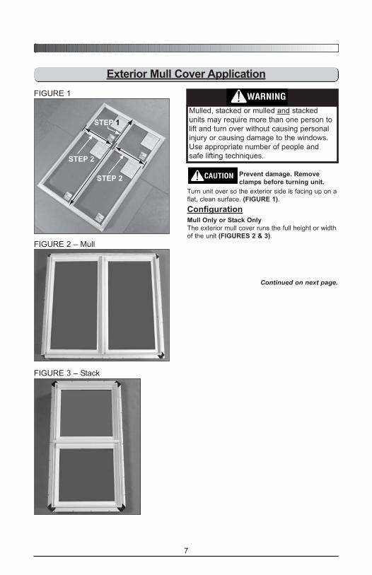
Mulled, stacked or mulled and stacked
units may require more than one person to
lift and turn over without causing personal
injury or causing damage to the windows.
Use appropriate number of people and
safe lifting techniques.
Prevent damage. Remove
clamps before turning unit.
Turn unit over so the exterior side is facing up on a
flat, clean surface. (FIGURE 1).
Configuration
Mull Only or Stack Only
The exterior mull cover runs the full height or width
of the unit (FIGURES 2 & 3).
Continued on next page.
Exterior Mull Cover Application
STEP 1
STEP 2
STEP 2
FIGURE 1
FIGURE 2 – Mull
FIGURE 3 – Stack

8
SEPARATEHORIZONTALMULL COVER
FULL-HEIGHTVERTICAL
MULL COVER
FIGURE 6 – 4-Way Mull or Mull/Stack
FIGURE 4 – 3-Way Mull/Stack
FIGURE 5 – 3-Way Mull/Stack
Configuration (cont.)
3-Way Mull/Stack Combinations
The horizontal mull cover installs first and runs the
full width of the unit (FIGURE 4). The vertical mull
cover is applied tight against the horizontal mull
cover (FIGURE 5).
4-Way Mull
The vertical mull cover is installed first (FIGURE
6). The vertical cover must run the full height of the
units and the horizontal covers are cut to the width
of each individual window unit.
Continued on next page.
Exterior Mull Cover Application (cont.)
9
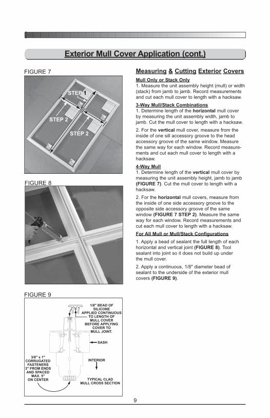
Measuring & Cutting Exterior Covers
Mull Only or Stack Only
1. Measure the unit assembly height (mull) or width
(stack) from jamb to jamb. Record measurements
and cut each mull cover to length with a hacksaw.
3-Way Mull/Stack Combinations
1. Determine length of the horizontal mull cover
by measuring the unit assembly width, jamb to
jamb. Cut the mull cover to length with a hacksaw.
2. For the vertical mull cover, measure from the
inside of one sill accessory groove to the head
accessory groove of the same window. Measure
the same way for each window. Record measure-
ments and cut each mull cover to length with a
hacksaw.
4-Way Mull
1. Determine length of the vertical mull cover by
measuring the unit assembly height, jamb to jamb
(FIGURE 7). Cut the mull cover to length with a
hacksaw.
2. For the horizontal mull covers, measure from
the inside of one side accessory groove to the
opposite side accessory groove of the same
window (FIGURE 7 STEP 2). Measure the same
way for each window. Record measurements and
cut each mull cover to length with a hacksaw.
For All Mull or Mull/Stack Configurations
1. Apply a bead of sealant the full length of each
horizontal and vertical joint (FIGURE 8). Tool
sealant into joint so it does not build up under
the mull cover.
2. Apply a continuous, 1/8" diameter bead of
sealant to the underside of the exterior mull
covers (FIGURE 9).
Exterior Mull Cover Application (cont.)
3/8" x 1"CORRUGATEDFASTENERS
3" FROM ENDSAND SPACED
MAX. 5"ON CENTER
1/8" BEAD OFSILICONE
APPLIED CONTINUOUSTO LENGTH OFMULL COVER
BEFORE APPLYINGCOVER TO
MULL JOINT.
TYPICAL CLADMULL CROSS SECTION
INTERIOR
SASH
FIGURE 8
FIGURE 9
STEP 1
STEP 2
STEP 2
FIGURE 7

10
For 4-Way Mull
3. Apply vertical mull cover first. Align cover’s legs
with exterior accessory grooves (FIGURE 10).
Slide cover flush with jamb (FIGURE 10A).
4. When exterior mull cover is properly aligned,
tap along the cover’s full length with a dead-blow
hammer to fully seat mull cover into window
exterior accessory grooves (FIGURE 10A). A
padded block can be used between the hammer
and mull cover (FIGURE 11).
Apply horizontal exterior mull covers next. They go
on like the vertical covers.
At the 4-way intersection, fit the horizontal mull
covers flush with the vertical cover (FIGURE 12).
For 3-Way Mull/Stack Combinations
Apply horizontal cover first, going from jamb
to jamb. Vertical mull cover is applied flush to
horizontal piece (FIGURE 13). For application,
follow Steps 3 and 4 above.
Mull Only or Stack Only
Apply full-length mull covers as described in Steps
3 and 4 above.
NOTE: After all mull covers are firmly seated along
their entire length, wipe off excess sealant
with a soft shop towel dampened with
denatured alcohol.
Exterior Mull Cover Application (cont.)
FIGURE 10
A
FIGURE 11
FIGURE 12
SEPARATEHORIZONTALMULL COVER
SEPARATEHORIZONTALMULL COVER
FULL-HEIGHTVERTICAL
MULL COVER
FIGURE 13
11
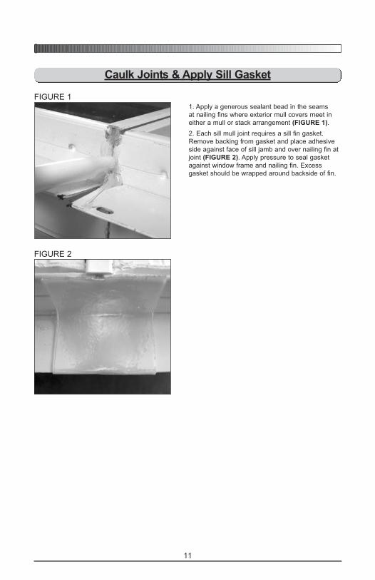
1. Apply a generous sealant bead in the seams
at nailing fins where exterior mull covers meet in
either a mull or stack arrangement (FIGURE 1).
2. Each sill mull joint requires a sill fin gasket.
Remove backing from gasket and place adhesive
side against face of sill jamb and over nailing fin at
joint (FIGURE 2). Apply pressure to seal gasket
against window frame and nailing fin. Excess
gasket should be wrapped around backside of fin.
Caulk Joints & Apply Sill Gasket
FIGURE 1
FIGURE 2

12
Install Drip Cap
1. Measure width of assembled units, jamb to jamb
(FIGURE 1). Mark drip cap at this length and cut
with a hacksaw.
2. Apply a continuous 1/8" diameter bead of
sealant to head. Start 1/2" from side jamb. Caulk
vertical face of nailing fin and continue along top
of head to other end of unit and up the opposite
nailing fin vertical face. Also apply sealant to the
mulled joints laying a 1/8" diameter bead 1/2" from
both sides of the joint. Add a third bead directly on
top of the joint (FIGURE 2).
3. Center drip cap, from side to side, over head of
combined unit and press firmly down into sealant
(FIGURE 3).
4. Secure drip cap to head with #8 x 1/2" stainless
steel TEK tip screws or #8 x 1/2" Phillips pan head
stainless steel self tapping screws.
Place screws 1" to 2" from each end of unit and
every 24" to 30" along length of drip cap (FIGURE
4).
5. Examine entire exterior and remove excess
sealant using a clean soft shop towel dampened
with denatured alcohol.
6. Allow sealant to dry before installing unit.
1/8" CAULK BEAD. RUNFULL WIDTHOF UNIT.
1/8" CAULK BEAD1/2" FROM BOTH
SIDES OF MULL JOINTAND ALONG JOINT.
1/8" CAULKBEAD 1/2"FROM BOTH ENDS.
FIGURE 1
FIGURE 2
FIGURE 3 FIGURE 4
When sealant is completely dry unit is ready
for installation. Follow the installation instruc-
tions packed with the individual windows.
Installation instructions are specific to window
types (casement, tilt, slider, etc.). Besides pro-
viding install data, the individual instruction
booklets cover details like design pressure
rating, screen & sash handling and other
installation details that vary between window
types.

13
Recommended Finishing Instructions
For Vinyl and Aluminum SurfacesVinyl and aluminum surfaces may be cleaned with mild soap and water. Hard to remove
stains and mineral deposits may be removed with mineral spirits.
• Do NOT clean with gasoline, diesel fuel, solvent based, or petroleum based
products.
• Do NOT use abrasive materials against vinyl, aluminum, or glass surfaces.
• Do NOT scrape or use tools that might damage the surface.
• Do NOT paint vinyl or aluminum surfaces.
For Wood SurfacesFor best results, the interior wood should be sealed immediately upon installation or upon
receipt especially if unit is being stored for ANY length of time. Remove all construction
residue before finishing.
1. Lightly sand surfaces being finished with 180 grit or finer sandpaper. Be careful not
to scratch the glass.
2. After sanding, clean-off sanding dust from the surface using lacquer thinner applied
to a cloth so the cloth is slightly damp. Let surface dry.
For Exterior and Interior Wood Surfaces-If painted surface is desired:
NOTE: If a “primed” unit is delivered with factory-applied primer paint, it may be painted
without repriming, providing the finish paint coat is applied within six (6) months
of unit installation. Factory-applied finish in either standard, optional orAccentials® colors do not require additional painting.
1. If unit requires priming or repriming, use only oil-based primer coats. Use compatible
oil or water-based finish coats. Refer to the paint manufacturers’ instructions.
2. Prime all exposed wood surfaces. Priming all surfaces helps prevent end splitting,
warping and/or checking.
3. Once primed, apply two (2) coats of paint (again on all exposed sides) to each item.
-If a stained surface is desired:
1. Use only oil-based stain and sealer for the first coat. A gel stain is easier to apply as
it does not easily run or drip. The clear top coat may be oil or water-based. A
pre-stain wood conditioner, applied before staining, will help softer woods like pine
absorb stain more evenly. Apply both wood conditioner and desired stain according
to the manufacturers’ instructions.
2. Apply one (1) coat of sealer to the surface and let dry. Using a spar (marine) varnish
as a sealer provides extra protection against sunlight and moisture. Let sealer dry
completely.
If no sealer is applied over stain, the wood will weather very rapidly
and defects will occur. Apply at least two (2) coats of sealer.
3. Before applying the next finish coat, make sure the previous coat is completely dry.
Then lightly sand previous finish coat with 180 grit or finer sandpaper. Clean off all
sanding dust and wipe surfaces with a tack cloth.
4. Apply next coat of desired finish to surface and let dry. Apply only one coat at a time.
5. For any additional coats of finish, repeat steps 3 and 4.
Always follow chemical manufacturers’ safety instructions when using chemicals to avoid
injury or illness.
14
Serious concerns have been raised about excessive moisture problems in homes and
other buildings that have Exterior Insulation Finish Systems, commonly referred to as
EIFS or Synthetic Stucco.
Many experts agree that a certain amount of water or moisture can be expected to enter
almost any building exterior system. The building system should allow such water and
moisture to escape or “weep” to the exterior, so no damage occurs. However, some
EIFS systems may not allow water or moisture that penetrates the wall system to
“weep” to the exterior. This can cause excessive moisture to accumulate within the wall
system, which can cause serious damage to wall and other building components. It has
been reported that so-called “barrier” EIFS systems are particularly prone to this
problem.
Moisture problems in any type of building structure can be reduced by proper design
and construction with appropriate moisture control considerations, taking into account
prevailing climate conditions. Examples of moisture control considerations include
flashing and/or sealing of all building exterior penetration points, use of appropriate
materials and construction techniques, adherence to applicable building codes, and
general attention to proper design and workmanship of the entire building system,
including allowances for management of moisture within the wall system.
Determination of proper building design, components and construction, including
moisture management, are the responsibility of the design architect, the contractors,
and the manufacturer of the exterior wall finish products. Questions and concerns about
moisture management issues should be taken up with these professionals. Weather
Shield Mfg., Inc. is not responsible for problems or damages caused by deficiencies in
building design, construction or maintenance, failure to install our products properly, or
use of our products in systems that do not allow for proper management of moisture
within the wall system.
Products With Synthetic Stucco

15
Notes

WS Part No. 1180961 1/05
PT Part No. 30899100 1/05
SNE Install 222 Part No. 210164 1/05 Printed in U.S.A. © 2005 Window Manufacturer