Embed Size (px)
Citation preview

Document ID: EDF-3434
Effective Date: 6/6/03 Revision ID: 0
Engineering Design File
Project No. 22522
Alternatives for Protection of Staging Area Liner Systems
Prepared for: U.S. Department of Energy Idaho Operations Office Idaho Falls, Idaho
Form 412.14 04/03/2003 Rev. 04
431.02 01/30/2003 Rev. 11
loc. Control AL I . Distribution:
(Name and Mail Stop)
ENGINEERING DESIGN FILE
a Ltaa FAWU Imc .5 b/h/03 M. Doornbos, MS 3930; D. Crisp, MS 4142; T. Borschel, MS 4142
EDFNo.: 3434 EDF Rev. No.: 0 Project File No.: 22522
. Title: Alternatives for Protection of Staging Area Liner Systems
. Index Codes: Buildinuype /SA SSC ID NA Site Area NA
. NPH Performance Category: or a N/A
,. EDF Safety Category: or a N/A SCC Safety Category: or N/A
I. Summary: This Engineering Design File presents the results of the liner system alternative analysis conducted for the INEEL CERCLA Disposal Facility Staging Piles. Liner system alternatives were developed based on literature review of currently available materials for a liner system and on examination of the advantages and disadvantages associated with each material. The primary requirement imposed on the alternative analysis was durability and permeability, attributes that are necessary for the liner system to perform its fundamental function as a barrier between the staged waste and the natural soil. Durability of the liner system covers the issues associated with the effectiveness of the liner system to withstand the anticipated equipment loading during its 15-year design life. Cost was also factored into the evaluation study to further narrow the aiternatives.
Five alternative liner systems that would achieve the 15-year design life are presented and discussed in this Engineering Design File. In these alternatives, high-density polyethylene geomembrane and hot mix asphalt concrete were considered for the barrier liner material. Paving asphalt concrete and compacted soil were considered for the protective layer or surface above the liner, owing to their potential in preserving the overall durability characteristics of the liner system. The advantages and disadvantages of each alternative are presented and examined in this study and an optimum alternative is recommended.
In addition, several short-term alternatives were also developed and evaluated to address staging a small amount of waste for a period of less than 2 years.
3. Review (R) and Approval (A) and Acceptance (Ac) Signatures: (See instructions for definitions of terms and significance of signatures.)
I R/A I Typed Name/Organization I Signature I Date 'erformer/ I I / / - 4uthor N/A King Sampaco/CH2M HILL #(J,/l& 5/30/03
:hecker R Mike Reimbold/CH2M HILL 5/30/03 rec h n ical
Page 1 of 2

431.02 OIl30/2003
'e rfo rm er/ hthor -ethnical ; hecker ndependent 'eer Reviewer if applicable) Ioc. Owner
ENGINEERING DESIGN FILE
RIA Typed NamelOrganization Signature Date
NIA CH2M HILL 5130l03
R CH2M HILL 5130l03
King Sampacol
Mike Reimboldl
Jay Dehnerl CH2M HILL
Tom Borschell R 5130103
EDF-3434 Revision 0
tequestor if applicable)
Rev. 11 Page 1 of 50
5130103 A ICDFPE
Ac BBWl 5130/03 Dan Crisp1
EDFNo.: 3434 EDF Rev. No.: 0 Project File No.: 22522
)oc. Control I
I . Title: Alternatives for Protection of Staging Area Liner Systems Page 1 of !. Index Codes:
BuildingIType NIA SSC ID NIA Site Area NIA
15130103
i. NPH Performance Category: or (XI NIA
1. EDF Safety Category: or NIA SCC Safety Category: or [XI NIA
). Summary: This Engineering Design File presents the results of the liner system alternative analysis conducted for the INEEL CERCLA Disposal Facility staging piles. Liner system alternatives were developed based on literature review of currently available materials for a liner system, and on examination of the advantages and disadvantages associated with each material. The primary requirements imposed on the alternative analysis were durability and permeability-attributes that are necessary for the liner system to perform its fundamental function as a barrier between the staged waste and the natural soil. Durability of the liner system addresses issues associated with the effectiveness of the liner system in withstanding the anticipated equipment loading during its 15-year design life. Cost was also factored into the evaluation study to further narrow the alternatives.
Five alternative liner systems that would each achieve the 15-year design life are presented and discussed in this Engineering Design File. In these alternatives, high-density polyethylene geomembrane and hot mix asphalt concrete were considered for the barrier liner material. Paving asphalt concrete and compacted soil were considered for the protective layer or surface above the liner, owing to their potential in preserving the overall durability characteristics of the liner system. The advantages and disadvantages of each alternative are presented and examined in this study, and an optimum alternative is recommended.
In addition, several short-term alternatives were also developed and evaluated to address staging a small amount of waste for a period of less than 2 years.
(Name and Mail Stop) I
If Yes, what category: 1. Does document contain sensitive unclassified information? 0 Yes No
1. Can document be externally distributed? IxI Yes 0 No

431.02 01 /30/2003 Rev. 11
ENGINEERING DESIGN FILE EDF-3434 Revision 0
Page 2 of 50
EDFNo.: 3434 EDF Rev. No.: 0 Project File No.: 22522
. Title: Alternatives for Protection of Staging Area Liner Systems Page 1 of I. Index Codes:
BuildingIType N/A SSC ID N/A Site Area N/A
0. Uniform File Code: 61 02 Disposition Authority: ENVI -h-I
1. For QA Records Classification Only: 0 Lifetime 0 Nonpermanent [7 Permanent
2. NRC related? 0 Yes (XI No 3. Registered Professional Engineer's Stamp (if required)
Record Retention Period: See List 9
Item and activity to which the QA Record apply:

431.02 0 1 /30/2003 Rev. 11
ENGINEERING DESIGN FILE
ABSTRACT
This Engineering Design File presents the results of the liner system alternative analysis conducted for the INEEL CERCLA Disposal Facility staging piles. Liner system alternatives were developed based on literature review of currently available materials for a liner system. The primary requirements imposed on the alternative analysis were durability and permeability. Durability of the liner system addresses the issues associated with integrity, effectiveness, and longevity of the liner system. Cost was factored into the evaluation study subsequently, to further narrow the alternatives.
Five alternative liner systems that would each achieve the 15-year design life are presented and discussed. In these alternatives, highdensity polyethylene geomembrane and hot mix asphalt concrete were considered for the barrier liner material. Paving asphalt concrete and compacted soil were considered for the protective layer or surface above the primary liner to preserve the overall durability characteristics of the liner system.
Each of the alternatives selected satisfies the essential requirements of durability and permeability of a liner system. With regards to durability, the hot mix asphalt concrete/fluid applied asphalt membrane liner composite appears to be superior over the high-density polyethylene geomembrane liner, especially where a compacted soil layer is used as protective soil. Both of the liner materials could perform very well as a barrier layer between the staged waste and the natural soil.
EDF-3434 Revision 0
Page 3 of 50
In addition, several short-term alternatives were developed and evaluated to address staging a small amount of waste for a period of less than 2 years.

43 1.02 01/30/2003 Rev. 11
ENGINEERING DESIGN FILE EDF-3434 Revision 0
Page 4 of 50
This page is intentionally left blank.
431.02 01 /30/2003 Rev . 11
ENGINEERING DESIGN FILE EDF-3434 Revision 0
Page 5 of 50
CONTENTS
ABSTRACT .................................................................................................................................................. 3
ACRONYMS ................................................................................................................................................ 7
1 .
2 .
3 .
4 .
5 .
INTRODUCTION .............................................................................................................................. 9
1.1 Background ............................................................................................................................... 9
1.2 Purpose and Scope .................................................................................................................... 9
MAJOR ASSUMPTIONS .................................................................................................................. 9
CRITERIA FOR ALTERNATIVE EVALUATION ........................................................................ 10
3.1 Regulations Pertaining to Staging Piles ................................................................................. 10
3.2 Liner Design Criteria .............................................................................................................. 10
3.2.1 Environmental Stresses ...................................................................................... 10 3.2.2 Equipment Loading ........................................................................................... 11 3.2.3 Stormwater Drainage ......................................................................................... 12
LINER SYSTEM ALTERNATIVES ............................................................................................... 12
4.1 High-Density Polyethylene ..................................................................................................... 12
4.1.1 Thickness Consideration .................................................................................... 13 4.1.2 Geomembrane Protective Soil ........................................................................... 14 4.1.3 Cushion Geotextile ............................................................................................ 14 4.1.4 Chemical Compahbility ..................................................................................... 14
Thickness Consideration, Mix Design, and Compaction ................................... 15 Fluid Applied Asphalt Membrane Coating ........................................................ 16
4.2.3 Chemical Compatibility ..................................................................................... 16
LINER SYSTEM ALTERNATIVES ............................................................................................... 16
5.1 Alternative 1 : High-Density Polyethylene with Protective Soil ............................................ 16
5.2 Alternative 2: High-Density Polyethylene with Asphalt Surface ........................................... 18
5.3 Alternative 3: Hot Mix Asphalt Concrete with Soil Cover .................................................... 19
5.4 Alternative 4: Hot Mix Asphalt Concrete with Asphalt Surface ............................................ 20
5.5 Alternative 5 : Hot Mix Asphalt Concrete Surface with Base Course Subgrade .................... 21
5.6 Basis of Cost Estimates .......................................................................................................... 23
. . .
4.2 Hot Mix Asphalt Concrete ...................................................................................................... 14
4.2.1 4.2.2

431.02 01 /30/2003 Rev . 11
ENGINEERING DESIGN FILE EDF-3434 Revision 0
Page 6 of 50
5.7 Short-Term Alternatives ......................................................................................................... 23
. 6 . CONCLUSIONS AND RECOMMENDATIONS ........................................................................... 24
7 . REFERENCES ................................................................................................................................. 26
Appendix A-Cost Estimates ...................................................................................................................... 29
Appendix B4alculations .......................................................................................................................... 39
FIGURES
1 . Alternative 1 schematic ..................................................................................................................... 17
2 .
3 . Alternative 3 scherztic ..................................................................................................................... 20
4 Alternative 4 schematic 21
5 .
Alternative 2 schematic ..................................................................................................................... 18
. .....................................................................................................................
Alternative 5 schematic ..................................................................................................................... 22
431.02 01 130/2003 Rev. 11
CERCLA
DOE
DOE-ID
EDF
EPA
ESCR
FAAM
HDPE
HMAC
ICDF
INEEL
PAC
RCRA
ROD
SSSTF
TSCA
ENGINEERING’DESIGN FILE
ACRONYMS
Comprehensive Environmental Response, Compensation and Liability Act
Department of Energy
Department of Energy Idaho Operations Office
Engineering Design File
Environmental Protection Agency
environmental stress cracking
fluid applied asphalt membrane
high-density polyethylene
hot mix asphalt concrete
INEEL CERCLA Disposal Facility
Idaho National Engineering and Environmental Laboratory
paving asphalt concrete
Resource Conservation and Recovery Act
Record of Decision
Staging, Storage, Sizing, and Treatment Facility
Toxic Substances Control Act
EDF-3434 Revision 0
Page 7 of 50

431.02 01/30/2003 Rev. 11
ENGINEERING DESIGN FILE EDF-3434 Revision 0
Page 8 of 50
This page is intentionally left blank. .

431.02 01/30/2003 Rev. 11
ENGINEERING DESIGN FILE EDF-3434 Revision 0
Page 9 of 50
Alternatives for Protection of Staging Area Liner Systems
1. INTRODUCTION
1.1 Background
The October 1999 Final Record of Decision, for the Idaho Nuclear Technology and Engineering Center, Operable Unit 3-13 (DOE-ID 1999) states that contaminated surface soils will be removed and disposed in the INEEL CERCLA Disposal Facility (ICDF). The ICDF Complex will be an on-Site facility for the treatment and disposal of low-level hazardous, mixed, and some Toxic Substances Control Act (TSCA) wastes. The ICDF Complex included necessary subsystems and support facilities to provide a complete waste disposal system. The major components of the ICDF Complex are the disposal cells (which include the evaporation pond and leachate collection system) and the Staging, Storage, Sizing, and Treatment Facility (SSSTF).
The ICDF Complex is a low-level, hazardous, TSCA, and mixed waste disposal facility (landfill cells and evaporation pond) with an authorized capacity of approximately 5 10,OOO yd3. The Record of Decision (ROD) states that Comprehensive Environmental Response, Compensation and Liability Act (CERCLA)-generated wastes within the Idaho National Engineering and Environmental Laboratory (INEEL) facility will be removed and disposed of in the ICDF Complex. The ICDF evaporation pond will provide treatment/disposal capability for CERCLA-generated aqueous wastes. The ICDF landfill can accommodate multiple cells, and each disposal cell will be engineered to meet the substantive requirements of DOE Order 435.1, “Radioactive Waste Management;” the Resource Conservation and Recovery Act (RCRA) Subtitle C; the Idaho Hazardous Waste Management Act; and TSCA polychlorinated biphenyl landfill design and construction requirements. The cells will be closed with an engineered cap to meet the ROD requirements.
1.2 Purpose and Scope
The ICDF Complex is scheduled to be operational in July 2003. A minimal amount of waste is contaminated soils that must subsequently be treated at the SSSTF. An area (bounded by four comers) has been identified at the ICDF Complex, wherein incoming waste that is not sent directly to the landfill will be unloaded and will comprise the bulk soil staging pile. The agencies have required that a liner be designed and constructed under the staging piles.
The purpose of this Engineering Design File (EDF) is to prepare a detailed alternative analysis and recommended proposal for the design and construction of a liner system for the staging piles. The factors examined in the alternatives analysis include liner integrity, effectiveness, longevity, and cost. These factors are summed into three broad categories of durability, permeability, and cost. The advantages and disadvantages of alternatives are discussed and an alternative is recommended.
2. MAJOR ASSUMPTIONS
The alternative analysis was based on the following major assumptions:
1. The maximum defined physical size of the storage area (as defined in the INEEL CERCLA Disposal Facility Complex Remedial Action Work Plan [DOE 20031) is 150 ft x 270 ft.

431.02 0 1 130/2003 Rev. 11
ENGINEERING DESIGN FILE EDF-3434 Revision 0
Page 10 of 50
2.
3.
4.
5 .
6.
7.
8.
The staging pile liner system would be constructed by building the system up above the existing grade (i.e., no excavation would be required to construct the liner system).
The length of time the waste remains stockpiled in the storage pile is short enough that the volume of the leachate expected while the waste is in the storage pile is small.
Because of the waste’s relatively short duration of time in the storage pile, the liner system would not require provision for any specialized leachate collection system.
The waste that would be stored in the staging pile would be covered and no operations would be allowed during inclement weather (e.g., periods of precipitation and high winds).
The materials stored in the staging pile would primarily include material from remediation sites that are similar to the silty soils and alluvium from the site.
The design life of the staging pile liner system is 15 years, which is consistent with the design life of the ICDF Complex. A shorter term (less than two years) design life, for small amounts of waste, was also considered.
The liner system will be disposed of in the landfill, before closure.
3. CRITERIA FOR ALTERNATIVE EVALUATION
3.1 Regulations Pertaining to Staging Piles
The bulk soil staging area will be managed according to 40 CFR 264.554, “Staging Piles.” The ICDF Complex Remedial Action Work Plan outlines the design and operational requirements (DOE-ID 2003).
The bulk soil staging pile area is not intended for conversion into a permanent disposal facility. Therefore, the liner system alternatives evaluated in this EDF are single-liner systems only.
3.2 Liner Design Criteria
According to the Environmental Protection Agency (EPA), the most important environmental condition to which a liner system is exposed in a waste pile is the overburden pressure (US EPA 1988). The maximum height of waste to be stored at a particular time is expected to be approximately 10 ft. Given that this anticipated waste height may be lower than a typical waste pile, other environmental factors may be more critical in the design of the bulk soil staging pile liner system. The primary concern for the ICDF Complex bulk soils staging area is to eliminate the possibility of secondary contamination from the stockpiled soils. The following section examines the possible environmental stresses that could act on the liner system for the staging piles. An attempt is then made to identify possible criteria to use as a basis for sizing the alternative liner systems considered in this evaluation study.
3.2.1 Environmental Stresses
The principal environmental stresses encountered in a typical liner system are divided into two types; namely, chemical stresses and physical stresses.
Chemical stresses are caused by dissolved organic and inorganic chemicals in the wastes and waste liquids that are contained in the waste impoundment facilities. Because it is difficult to characterize the

431.02 01 /30/2003
ENGINEERING DESIGN FILE EDF-3434 Revision 0
Rev. 11 Page 11 of 50
mechanics of chemicals inducing stresses in the liner systems, the effects on the properties of a liner system are emphasized instead. Examples of these effects are manifested by the following:
1. Degradation of the base polymer of a liner system through chemical processes such as oxidation and hydrolysis, which results in embrittlement and loss of physical properties of the liner that may be important to its performance
2. Depolymerization which results in softening and loss of physical properties
3. Absorption of waste constituents, which can result in increased permeability and loss in strength and other physical properties, if the amounts become sufficiently large.
The effects of chemical stress may take extended periods of time to become apparent, particularly when the concentration of aggressive constituents in a waste liquid is low.
Physical stresses are independent of any chemical stresses and can take place primarily during construction and during the early service life of a waste facility when the waste liquid is not in contact w2h the liner or other construction materials. Many factors can induce physical stresses to the liner - -.- system, as reported in the literature (U.S. EPA 1988, 1983). However, the most applicable to the bulk soil staging pile are as follows:
1. Stresses during installation (laying out) of the liner on the ground
2. Stresses due to dropped objects, such as tools, which could result in puncture of the liner
3. Stresses due to traffic
4. Stresses over irregularly shaped surfaces due to large aggregates next to the surface of the flexible membrane liner, or due to differential settlement in the case of a less flexible asphalt concrete liner.
A combination of physical and chemical stresses could also occur, which could affect the liner system in several different ways. For example, absorption of organics and subsequent swelling of flexible membrane liners can cause the liners to increase permeability. In addition, semicrystalline liners under mechanical stresses when in contact with some chemicals can crack by environmental stress cracking (ESCR) .
The choice of the materials for use in the liner system is dependent on the anticipated physical and chemical stresses. Because there are various types of liner materials available, highdensity polyethylene (HDPE) and hot mix asphalt concrete (HMAC) were used as the basis for this alternatives evaluation, as the design requirements could vary depending on each different liner material involved.
3.2.2 Equipment Loading
Construction equipment considered in this liner system alternative evaluation study, as anticipated during the operation of the waste pile facility, consist of the following:
Cat 966-G Front-End Loader
Cat 775E Dump Truck

431.02 01 130M003 Rev. I1
ENGINEERING DESIGN FILE EDF-3434 Revision 0
Page 12 of 50
0 Cat 420 Rubber-Tired Backhoe
0 Cat 246 Bobcat Loader.
3.2.3 Stormwater Drainage
The surface of the bulk soil staging area would be elevated slightly above the surrounding grades based on the thickness of the liner systems and the need to promote stormwater runoff. The surface of the staging area would be sloped a minimum of 2% to promote runoff and minimize the potential for standing water. The drainage from the bulk soil staging area would enter the sitewide stormwater system after exiting the storage area.
4. LINER SYSTEM ALTERNATIVES
Various liner systems are currently available, but the ones considered in the alternative analysis were limited to the criteria discussed in the previous section. The major requirements imposed in the alternative analysis were durability and permeability, in order for the liner system ic perform its fundamental functions. These general criteria are believed to cover the factors stated previously in the scope of work, namely: integrity, effectiveness, and longevity of the liner system. Cost was factored into the equation subsequently, to narrow the options.
Based on the criteria discussed above, the primary liner systems considered were limited to the following materials:
Highdensity polyethylene (HDFE)
Hot mix asphalt concrete (HMAC).
The following reasons led to the decision to consider these two materials for the primary liner:
1. The need to simplify the evaluation process, considering the relatively noncritical nature of the liner system design for waste piles
2. The lack of specific regulatory criteria for liner system design of waste piles
3. The difficulty of establishing a distinct quantitative comparison between alternatives consisting of various types of liner materials and components in the liner system, since these materials have differing physical and chemical properties, field behavior, and responses to environmental stresses.
4.1 High-Density Polyethylene
Although HDPE is the only type of geomembrane discussed in this evaluation, other types may be considered during implementation if anticipated waste types can be established that are compatible with the geomembrane material. These other liners (such as XR-5, and PVC) could offer even better advantages than HDPE, including lower coefficient of thermal expansiodcontraction, higher flexibility (elongation at yield), greater puncture resistance, factory welding so that larger panels can be deployed, and easier field seaming.
Over the past few years, HDPE has been an enormously popular product for use as a liner in waste containment applications due to its ultraviolet resistance, low cost, and very good overall chemical

431.02 01M012003 Rev. 11
ENGINEERING DESIGN FILE EDF-3434 Revision 0
Page 13 of 50
resistance. The standard minimum HDPE thickness required to provide adequate puncture resistance is 60 mil (Koerner 1998).
Despite its popularity, HDPE has some disadvantages, as reported in the literature. Some of the disadvantages that are applicable to the bulk soil staging pile liner system design include the following:
1. Being sensitive to ESCR due to its crystal lattice structure
2. Being a very stiff “flexible” liner and having a high coefficient of thermal expansion, which often require special design considerations
3. Being almost impossible to repair without the use of an expensive extrusion gun
4. Requiring field welding (on most environmental grade HDPE liners), which greatly increase installation and third party field quality control costs
5. Being fabricated in widths of 22 ft, thus requiring field seaming at joints during installation.
4.1.1 Thickness Consideration
The thickness of an HDPE liner is related to the pressures exerted on it. The current design mechanics are based on deformations that the liner might experience during its service life (Koerner 1998). These deformations might be caused by the following:
1. Areal differential settlement of subgrade soils
2. Settlement of backfilled zones beneath the liner (e.g., in pipe trenches)
3. Localized settlements around pieces of aggregate or localized “soft” areas beneath the liner
4. Any kind of anomalous conditions that place the liner in tension.
The minimum liner thickness recommended for an HDPE geomembrane in a typical liner design is 1.5 mm (60 mil) (Koerner 1998). Thus, in a typical design, the first step is to assume the minimum recommended thickness of 60 mil and then verify this thickness for adequacy, according to whichever of the deformations discussed above is critical to the project.
For the bulk soil staging pile, the liner system is envisioned to be constructed on a properly prepared, leveled, and compacted subgrade. As stated in the Geotechnical Report for the Conceptual Design of the ZCDF ut Waste Area Group 3, Operable Unit 3-13 (DOE-ID 2000), the site subgrade soils appear to consist of primarily medium dense to very dense silty sand and gravel materials. The Standard Penetration Test blowcounts associated with these materials in the upper 5 f t ranged between 23 and 50 blows per foot and generally increase with depth. With proper methods of subgrade preparation, it is expected that differential settlements associated with the subgrade soils would be very small.
It is expected that a soil cover will be used above the HDPE liner and that the subgrade may consist of sand and gravelly materials. Therefore, localized settlements, formed as a result of loading on top of the liner around pieces of aggregate in the subgrade (see Item 3 above), may need to be checked for the staging pile liner design, as discussed in the next section.
431.02 01130/2003 Rev. 11
ENGINEERING DESIGN FILE EDF-3434 Revision 0
Page 14 of 50
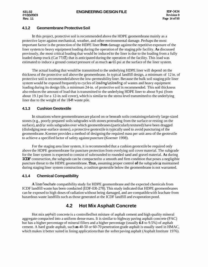
4.1.2 Geomembrane Protective Soil
In this project, protective soil is recommended above the HDPE geomembrane mainly as a protective layer against mechanical, weather, and other environmental damage. Perhaps the most important factor is the protection of the HDPE liner from damage against the repetitive exposure of the liner system to heavy equipment loading during the operation of the staging pile facility. As discussed previously, the most critical loading that would be induced to the liner is due to the loading from a fully loaded dump truck (Cat 775E) that is anticipated during the operation of the facility. This load was estimated to induce a ground contact pressure of as much as 65 psi at the surface of the liner system.
The actual loading that would be transmitted to the underlying HDPE liner will depend on the thickness of the protective soil above the geomembrane. In typical landfill design, a minimum of 12 in. of protective soil is recommended above the low-permeability liner. Because the bulk soil staging pile liner system would be exposed frequently to cycles of loadinghloading of wastes and heavy equipment loading during its design life, a minimum 24-in. of protective soil is recommended. This soil thickness also reduces the amount of load that is transmitted to the underlying HDPE liner to about 9 psi (from about 19.1 psi for a 12-in. soil cover), which is similar to the stress level transmitted to the underlying liner due to the weight of the 1 0 4 waste pile.
4.1.3 Cushion Geotextile
In situations where geomembranes are placed on or beneath soils containing relatively large-sized stones (e.g., poorly prepared soils subgrades with stones protruding from the surface or resting on the surface), and/or soils subgrades over which geomembranes (particularly textured) have been dragged (dislodging near-surface stones), a protective geotextile is typically used to avoid puncturing of the geomembrane. Koemer provides a method of designing the required mass per unit area of the geotextile to achieve a specified factor of safety against puncture (Koerner 1998).
For the staging area liner system, it is recommended that a cushion geotextile be required only above the HDPE geomembrane for puncture protection from overlying soil cover material. The subgrade for the liner system is expected to consist of subrounded to rounded sand and gravel material. As during ICDF construction, the subgrade can be compacted to a smooth and firm condition that poses a negligible puncture threat to the HDPE geomembrane. Thus, assuming proper control of the subgrade is maintained during staging liner system construction, a cushion geotextile below the geomembrane is not warranted.
4.1.4 Chemical Compatibility
A linerfieachate compatibility study for HDPE geomembrane and the expected chemicals from ICDF landfill waste has been conducted (EDF-ER-278). This study indicated that HDPE geomembranes can be exposed to high doses of radiation without being damaged, and are compatible with leachate from hazardous waste landfills such as those generated at the ICDF landfill and evaporation pond.
4.2 Hot Mix Asphalt Concrete
Hot mix as#alt concrete is a controlled hot mixture of asphalt cement and high quality mineral aggregate compacted into a uniform dense mass. It is similar to highway paving asphalt concrete (PAC) but has a higher percentage of mineral fillers and a higher percentage (usually 6.5 to 9.5%) of asphalt cement. A hard grade asphalt, such as 40-50 or 60-70 penetration grade asphalt is usually used in HMAC, which makes it better suited in lining applications than the softer paving asphalt (Asphalt Institute 1976).

431.02 ENGINEERING DESIGN FILE EDF-3434 Revision 0
Page 15 of 50 01/30/2003 Rev. 11
Hot mix asphalt concrete can be compacted into a permeability of less than lo-’ cmlsec (Hinkle 1976). For waste containment applications, the major factor to consider is the selection of an aggregate that is compatible with the waste. For example, the mix design should avoid using aggregates containing carbonates if highly acidic wastes are anticipated.
Hot mix asphalt concrete offers the following advantages:
1.
2.
3.
4.
5 .
6.
7.
8.
1.
2.
HMAC is resistant to light vehicular traffic and effects of weather extremes (such as temperature).
It retains enough flexibility to conform to slight deformations of the subgrade and avoid rupture from low-level seismic activity.
It can be placed with conventional paving equipment and compacted to the required thickness (Asphalt Institute 1966).
It is a durable material, as evidenced by its use dating back centuries as a water-resistant material (US. EPA 1983).
It has shown resistance to acids, bases, inorganic salts (to a 30% concentration) and to some organic compounds found in industrial wastes (Asphalt Institute 1976).
It has good resistance to inorganic chemicals and low permeability to corrosive gases such as hydrogen sulfide and sulfur dioxide.
It exhibits self-healing properties because of its viscoelastic nature. This property suggests that cracks resulting from seismic or subsidence events would heal without involving outside forces, such as heating or compaction (Mancini et al. 1995).
It can be constructed with a conventional paving machine in desired lifts to achieve a low permeability.
The disadvantages of HMAC include the following:
Hot mix asphalt concrete is generally not resistant to organic solvents and chemicals, particularly hydrocarbons in which they are partially or wholly soluble.
It is not an effective liner for disposal sites containing petroleumderived wastes or petroleum solvating compounds such as oils, fats, aromatic solvents, or hydrogen halide vapors.
4.2.1 Thickness Consideration, Mix Design, and Compaction
In applications where HMAC is used as an impermeable lining, the required thickness depends on the desired permeability, the percentage of asphalt used, and the gradation of the aggregate being used. Frequently, however, the thickness is decided based on previous experience. The most common thickness reported in the literature for hydraulic applications is 2 to 4 in. to achieve the minimum permeability of the liner (Styron and Fry 1979, Haxo 1976, Hinkle 1976). Permeability of less than 1 x been reported for this range of thickness (Hinkle 1976). The most common mix uses roughly 7 to 11% of asphalt concrete and aggregates, having less than 10% passing the US. Standard Sieve No. 200.
xdsec has” . ‘
Compaction of asphalt during placement dictates the quality of the finished liner (Bureau of Reclamation 1963). The Asphalt Institute recommends that the liner should be compacted to at least 97%

431.02 01 /30E003
ENGINEERING DESIGN FILE EDF-3434 Revision 0
Rev. 11 Page 16 of 50
of the density obtained by the Marshall Method or less than 4% voids (Asphalt Institute 1976,1981). The subgrade should be properly prepared and compacted before placement.
4.2.2 Fluid Applied Asphalt Membrane Coating
Fluid applied asphalt membrane (FAAM) coating contains mostly asphalt with less than 15% polymer, and is applied by spraying the coating into the surface of the HMAC to create a more impermeable and flexible liner. The FAAM coating has been used with favorable feedback at the Hanford Site Permanent Isolation Surface Barrier (Mancini et al. 1995). The FAAM application is seamless and forms a strong bond to the surface of the underlying HMAC, which prevents lateral water movement between the two materials and provides a stable construction surface. The composite asphalt banier (HMAC/FAAM) is reported to be functionally equivalent to an RCRA bentonite clay and HDPE barrier. It has exceeded the RCRA performance criteria, demonstrating permeability of less than 2 x 10% cdsec for HMAC, and less than 1 x lo-" cdsec for FAAM coating.
A lower viscosity asphalt, such as AR-4OOO graded asphalt cement, is more appropriate than AR-6OOO for the HMAC mix for a warm, arid climate (Mancini et al. 1995). About 7 to 8% by weight of AR-4000 compacted to at least 96% of maximum density was used.
4.2.3 Chemical Compatibility
Hot mix asphalt concrete liners are generally not resistant to organic solvents and chemicals, particularly hydrocarbons in which they are partially or wholly soluble. These characteristics limit the effectiveness of these types of liners for disposal sites containing petroleumderived wastes or petroleum solvating compounds, such as oils, fats, aromatic solvents, or hydrogen halide vapors.
5. LINER SYSTEM ALTERNATIVES
This section outlines and describes the five alternatives considered for the staging area liner systems that would be expected to last for the 15-year design life. The advantages, disadvantages, and estimates of costs of each alternative are discussed and presented. The basis of the cost estimates is presented in Section 5.5. Details of the cost estimates for each alternative are attached in Appendix A. A copy of the relevant calculations is given in Appendix B.
In addition, several short-term alternatives were developed and evaluated to address staging a small amount of waste for a period of less than 2 years. This analysis is presented in Section 5.7.
5.1 Alternative 1 : High-Density Polyethylene with Protective Soil
Alternative 1 consists of a 60-mil HDPE liner, a 12-02 cushion geotextile, and 24-in. thick protective soil. As discussed in the previous section, the 12-02 geotextile is provided for protection of the HDPE geomembrane liner against puncture, and as a cushion to prevent potential damage to the HDPE during construction and operation of the waste pile. Figure 1 shows the schematic section of the Alternative 1 liner system. As discussed previously, the 24-in. protective soil is provided as a protective layer against mechanical, weather, and other environmental damage to the HDPE. Using a 24411. thick soil cover (as opposed to the typical 12-in. minimum) would minimize the effects of surficial equipment loading to the underlying liner, specifically reducing the live load stresses to a level similar to the anticipated overburden pressure from the waste pile. The 24-in. thickness is also necessary to minimize the risk that equipment operating above the liner could accidentally dig into the soil cover, thereby damaging the HDPE liner and compromising its primary function as an impermeable barrier layer.

431.02 01 l3Ol2003 Rev. 11
ENGINEERING DESIGN FILE EDF-3434 Revision 0
Page 17 of 50
1
PLTERNATNE #1 m-
Figure 1. Alternative 1 schematic.
Prior to placement of the HDPE liner, the existing surficial subgrade soil should be properly prepared, leveled, and compacted to a density of at least 95% of the maximum dry density in accordance with ASTM D1557. The soil cover should be compacted in lifts of 6 to 8 in., and to a density of at least 95% of the maximum dry density.
The cost of this alternative is estimated to be $155,000.00. Potential annual costs associated with maintenance and replenishment to maintain the minimum required thickness of the protective soil cover are estimated at $10,500. (Note: these costs are presented in 2003 dollars.)
The major advantages of this liner system alternative are as follows:
The arrangement is simple and straightforward and, thus, easy to construct.
0 As long as damage to the HDPE geomembrane would not occur, the liner system configuration could work effectively.
Large potential savings in cost could be realized if the protective soil could be obtained from on-Site excavations such as the site alluvium.
The major disadvantages for this alternative are as follows:
0 There is no hard and flat surface on which the equipment could operate.
43 1.02 01 130J2003 Rev. 11
ENGINEERING DESIGN FILE EDF-3434 Revision 0
Page I8 of 50
0 Uncertainty exists in the durability of the 24-in. protective soil above the HDPE for the 15year design life of the facility. There is a high risk of potential damage to the geomembrane liner, resulting from the equipment (particularly a backhoe) accidentally digging into the soil cover during operation of the facility. The soil cover could look like the same material as the waste being stockpiled, makmg it difficult for equipment operators to determine if they are digging into the soil cover.
Soil cover will likely require periodic maintenance and replenishment to maintain minimum required thiclmess. It is assumed that 6 in. of soil cover would require replacement once every year during the design life of the staging area.
When the facility is no longer needed, the liner and soil cover would require higher disposal cost, due to larger material volumes.
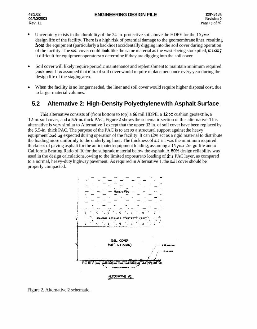
5.2 Alternative 2: High-Density Polyethylene with Asphalt Surface
This alternative consists of (from bottom to top) a 60 mil HDPE, a 12 oz cushion geotextile, a 12-in. soil cover, and a 5.5-in. thick PAC, Figure 2 shows the schematic section of this alternative. This alternative is very similar to Alternative 1 except that the upper 12 in. of soil cover have been replaced by the 5.5-in. thick PAC. The purpose of the PAC is to act as a structural support against the heavy equipment loading expected during operation of the facility. It can also act as a rigid material to distribute the loading more uniformly to the underlying liner. The thickness of 5.5 in. was the minimum required thickness of paving asphalt for the anticipated equipment loading, assuming a 15year design life and a California Bearing Ratio of 10 for the subgrade material below the asphalt. A 50% design reliability was used in the design calculations, owing to the limited exposure to loading of this PAC layer, as compared to a normal, heavy-duty highway pavement. As required in Alternative 1, the soil cover should be properly compacted.
Figure 2. Alternative 2 schematic.

431.02 01 130/2003 Rev. 11
ENGINEERING DESIGN FILE EDF-3434 Revision 0
Page 19 of 50
The cost of this alternative is estimated to be $219,000.00. Potential annual costs associated with maintenance and repair to maintain the PAC layer are estimated at $3,800. (Note: these costs are presented in 2003 dollars.) These maintenance costs assume that a seal coat is applied to the PAC once every 3 years.
The advantages of Alternative 2 are as follows:
The hard, flat surface layer of the PAC provides a good working surface for the loadinghnloading of the wastes.
The PAC surface provides a rigid layer that would offer better load distribution to the underlying liner.
The PAC layer is a semi-impervious layer that could minimize leachate infiltration and migration into the underlying liner.
The presence of the PAC layer could reduce the impact and dynamic loadings caused by heavy equipment operating at the surface of the liner system.
The PAC serves as a rigid barrier that ensures protection of the underlying liner from accidental damage by operating equipment. The rigid layer would not allow any equipment to dig into the soil layer.
The disadvantages of Alternative 2 are as follows:
The PAC layer is placed directly in contact with the waste pile and could undergo chemical reactions. Potential reactions would be dependent on the chemical constituents of the waste pile.
The PAC layer would require occasional repairhaintenance. It is assumed that application of a seal coat would be required once every 3 years during the design life of the staging area.
5.3 Alternative 3: Hot Mix Asphalt Concrete with Soil Cover
This alternative is similar to Alternative 1, with the exception that the HDPE geomembrane liner and the 12-02 geotextile is replaced with 4-in. thick HMAC coated with FAAM. The HMAC would need to be compacted in 2 lifts, at 2 in. per lift, to achieve the permeability requirements. The FAAM coating will provide additional impermeability and flexibility at the surface of the HMAC. Figure 3 shows the schematic section of this alternative.
The cost of this alternative is estimated to be $185,000.00. Potential annual costs associated with maintenance and replenishment to maintain the minimum required thickness of the protective soil cover are estimated at $10,500. (Note: these costs are in 2003 dollars.) Alternative 3 has advantages similar to the first three items for Alternative 1. However, because of its thicker section and rigidity, the HMAC liner’s durability is superior to that of the HDPE, from the standpoint of vulnerability to physical damage due to heavy equipment loading. Construction of the HMAC is a seamless process that can be performed with conventional paving equipment and compacted to the required thickness and permeability.

431.02 01 13012003 Rev. 11
ENGINEERING DESIGN FILE
k
EDF-3434 Revision 0
Page 20 of 50
Figure 3. Alternative 3 schematic.
The major disadvantage of Alternative 3 is that a linerfleachate compatibility study may be required to demonstrate that no adverse effects to the liner's permeability characteristics could occur in the event of a leachate infiltratiodmigration into the liner. Because of the relative rigidity of the asphalt (compared to HDPE), it has greater potential for cracking. This problem, however, was dealt with by providing the FAAM coating, which improves the flexibility, impermeability, and self-healing properties of the HMAC. As in Alternative 1, this alternative will likely require periodic maintenance and replenishment to maintain minimum required thickness of the protective soil cover.
5.4 Alternative 4: Hot Mix Asphalt Concrete with Asphalt Surface
This alternative consists of 5.5411. thick PAC over a 4411. HMAC liner with FAAM coating. No soil cover is required between the PAC and HMAUFAAM layers, as the PAC could be constructed directly on top of the H M A C F M . Figure 4 shows the schematic section of this alternative.
The cost of this alternative is estimated to be $199,000.00. Potential annual costs associated with maintenance and repair to maintain the PAC layer are estimated at $3,800. iibte: these costs are presented in 2003 dollars.) These maintenance costs assume that a seal coat is applied to the PAC once every 3 years.

431.02 0 1/30/2003 Rev. 11
ENGINEERING DESIGN FILE EDF-3434 Revision 0
Page 21 of 50
Figure 4. Alternative 4 schematic.
This alternative retains the advantages associated with the presence of the rigid PAC layer at the surface, as discussed for Alternative 2. An additional advantage is that the 12-in. layer of soil cover is not required above the HMACEAAM, which could reduce the cost, and at the same time could demonstrate performance equivalent to Alternative 2. The resulting liner thickness for this alternative is only about 12 in., which is less than half of the thickness of the other three alternatives. This reduced thickness could translate to savings in the cost of having to build ramps for trucks to access the facility.
The major disadvantages discussed for Alternative 2 also apply to this alternative. In addition, because of the relatively thinner section, the heavy wheel loads are now closer to the HMAC/FAAM liner system, making it vulnerable to physical damage that could result from repetitive action of heavy equipment loading.
5.5 Alternative 5: Hot Mix Asphalt Concrete Surface with Base Course Subgrade
This alternative consists of (from bottom to top) a 12-in. thick granular base course, and a 5.5-in. thick HMAC. Figure 5 shows the schematic section of this alternative. The purpose of the HMAC is to act as a structural support against the heavy equipment loading expected during operation of the facility.
The thickness of 5.5 in. was the minimum required thickness of HMAC for the anticipated equipment loading, assuming a 15-year design life and a California Bearing Ratio of 10 for the subgrade material below the asphalt. A 50% design reliability was used in the design calculations, owing to the limited exposure to loading of this HMAC layer, as compared to a normal, heavyduty highway pavement. As required for the soil cover in Alternative 2, the granular base course must be properly compacted.
The cost of this alternative is estimated to be $200,000. Potential annual costs assciated with maintenance and repair to maintain the HMAC layer are estimated at $3,800. (Note: these costs are presented in 2003 dollars.) These maintenance costs assume that a seal coat would be applied to the HMAC once every 3 years.

431.02 01/30/2003 Rev. 11
ENGINEERING DESIGN FILE EDF-3434 Revision 0
Page 22 of 50
Figure 5. Alternative 5 schematic.
The advantages of Alternative 5 are as follows:
0 The hard, flat surface layer of the HMAC provides a good working surface for the loadinghnloading of the wastes.
The HMAC layer is a semi-impervious layer that would minimize leachate infiltration and migration.
The HMAC serves as a rigid barrier that ensures protection of the underlying soil. The rigid layer would not allow digging of any equipment into the underlying soil.
The HMAC layer can be visually inspected for damage.
0
0
The disadvantages of Alternative 5 are as follows:
The HMAC layer is placed directly in contact with the waste pile and could undergo chemical reactions, dependhg on the chernka! constituents of the waste pile.
Potential cracking of the HMAC surface due to repetitive equipment loading would require periodic maintenance. It is assumed that application of a repair seal coat to the HMAC would be required once every 3 years during the design life of the staging area.

431.02 01 130l2003 Rev. 11
ENGINEERING DESIGN FILE EDF-3434 Revision 0
Page 23 of 50
5.6 Basis of Cost Estimates
The assumptions used in the cost estimates presented in this EDF are listed below. The printout of spreadsheets that were used to develop the cost estimates are attached in Appendix A. The unit costs used in this estimate were based mostly on historical information from CH2M HILL, and may not necessarily reflect the most current, local unit costs. The cost estimates only include construction costs and applicable maintenance costs. Maintenance costs are based on estimated annual costs and are presented in 2003 dollars.
0 Plan Area = 150 ft x 270 ft
0 60 mil HDPE (textured) - $7.00 per yd2
0 12 oz geotextile - $1.50 per yd2
0 Soil cover above liner - $5.00 per yd3 (unit cost of onsite native materials)
0 Granular base course - $15.00 per yd3 (material cost only)
0
0
Paving asphalt concrete (PAC) - $40.00 per ton
HMAC with FAAM Coating - $55.00 per ton
HMAC - $50.00 per ton
0 HMAC or PAC Repair seal coat - $2.50 per yG2
0 Unit weight of asphalt = 145 pounds per ft3
0 Miscellaneous (allowance for clearing/grabbing/etc.)- 10% of project cost
0 Mobilization costs - 10% of project cost (includes bonds, insurance, temporary facilities, health and safety, and demobilization)
0 Contingency - 30% of project cost
Site Factor - 20% of project cost (includes 40-hr Health and Safety training, monitoring, security constraints).
5.7 Short-Term Alternatives
Several short-term alternatives also were developed and evaluated to address staging a small amount of waste for a period less than 2 years. The criteria used for this alternative included the following:
Maximum staged volume of 840 yd3, which is an area approximately 70 ft2
0 Maximum storage period of 2 years
Permissible to rip or tear a flexible liner during waste removal.

431.02 01/30/2003 Rev. 11
ENGINEERING DESIGN FILE EDF-3434 Revision 0
Page 24 of 50
The following alternatives were developed as part of the short-term evaluation:
Asphalt concrete pavement surface placed directly on existing subgrade
Geomembrane placed on sand or geotextile cushion
Nonreinforced lean concrete mud mat.
The asphalt concrete pavement surface would consist of one lift (2 in.) of asphalt placed on the existing subgrade at the SSSTF. The area would be sloped to drain at a minimum of 2%. The waste would then be placed, graded to eliminate depressions on top of the waste, and covered with tarps. During removal of waste, the asphalt surface would provide a surface that allows easy removal. Following removal and disposal of all waste, the asphalt would be removed and placed in the ICDF landfill. The cost of this alternative would be approximately $lO,OOO, based on a total area of 4,900 ft* to be paved, and a cost of $2.00 per ydz of asphalt.
The geomembrane alternative would consist of placing a cushion layer on the axisting s&grade. The area would be sloped to drain a minimum 2%. The cushion could be sand material obtained from the sand stockpile at the permanent stockpile location, or a cushion geotextile. The geomembrane could be HDPE, PVC, polypropylene, or similar material. Several materials other than HDPE provide one piece of material that can be placed with no seaming. A HDPE geomembrane would require seaming and therefore some quality control would be required to ensure a watertight seam. An access ramp of 3 ft of clean soil would be required at the edge of the geomembrane to allow trucks to dump from a protected liner area. The waste would continue to be placed and spread in a 3-fi-thick lift, and then additional waste could be placed on top of the initial 3 ft layer of waste. The waste would then be graded to eliminate any depressions and covered with tarps. During removal of the waste from the geomembrane lined area, caution used by the loader operator would reduce punctures. However, in the removal of all the waste, punctures are likely to occur. Following removal of all waste, the geomembrane and portions of the underlying soil should be removed and disposed of in the ICDF landfill. The estimated cost for this alternative would be approximately $6,000.
The concrete mud mat would consist of excavating a 6-in.-thick staging area and pouring a lean concrete mix. This mud mat would provide a surface similar to the asphalt alternative except that cracking would be much more likely for the nonreinforced concrete. The estimated cost for this alternative would be approximately $8,200, based on a total volume of 91 yd3 at a cost of $90.00 per yd3 of concrete.
6. CONCLUSIONS AND RECOMMENDATIONS
This EDF presents the results of the liner system alternative analysis conducted for the ICDF Complex bulk soil staging pile. The bulk soil staging area will be managed in accordance with 40 CFR 264.554. The ICDF Remedial Action Work Plan outlines the design and operational requirements (DOE-ID 2003).
Alternatives were developed based on literature review of currently available materials. The advantages and disadvantages associated with using each of these materials wei’e examined. The primary requirement imposed on the alternative analysis was durability of the liner system in order for the liner system to perform its fundamental function as a barrier between the staged waste and the natural soils. Durability of the liner system addresses the issues associated with integrity and longevity of the liner system. In this liner system alternative evaluation, liner effectiveness is defined as the ability of the liner system to perform as follows:

431.02 01 130l2003 Rev. 11
ENGINEERING DESIGN FILE EDF-3434 Revision 0
Page 25 of 50
Properly function as a barrier between the staged waste and the natural soil.
Demonstrate adequate strength andor flexibility characteristics to withstand physical and chemical stresses.
Five alternative liner systems that achieve the desired 15-year design life are presented and discussed in this EDF. In these alternatives, the materials considered for the primary liner material include the HDPE geomembrane, the HMAC with or without FAAM. Liner system components above the liner were selected according to their effectiveness as a protective layer or surface to preserve the overall durability characteristics of the liner system. The materials that were assessed to satisfy these requirements (with due consideration to cost) are PAC and compacted soil cover. Specifically, the five liner system alternatives presented in this EDF include the following:
1. Alternative 1: HDPE with Soil Cover
2. Alternative 2: HDPE with PAC Surface
3. Alternative 3: HMAC/FAAM with Soil Cover
4. Alternative 4: HMAWAAM with PAC Surface
5 . Alternative 5: HMAC Surface with Base Course Subgrade.
Because these alternatives were chosen according to the established criteria mentioned previously, each of the alternatives satisfies the essential requirements of durability and permeability of a liner system, amidst some potential disadvantages identified for each of the alternatives.
With regards to durability, the HMAC appears to be superior to the HDPE geomembrane liner, especially where a compacted soil layer is used as a protective soil cover. Both the HDPE and HMAC liners could perform very well as an impermeable barrier layer against leachate migration.
With regards to the component above the primary liner, the PAC protective surfacing appears to be superior to the compacted soil cover for this application, because of the potential exposure of the liner system to repeated live loads during its 15-year design life. However, the potential of cost savings associated with using soil cover instead of the PAC surface may be so great (especially if onsite soils are available) that modifications could be made to Alternatives 1 and 3 to improve the durability rating of the liner system. Such modifications could involve increasing the cover thickness to further reduce the risk of damaging the underlying liner.
With respect to cost, the five alternatives are similar (approximately 30% difference in construction cost between the lowest and the highest). The construction cost breakdown is as follows:
0 Alternative 1 (HDPE plus Protective Soil Cover) - $155,000.00
Alternative 2 (HDPE plus Protective Soil Cover plus PAC) - $219,000.00
Alternative 3 (HMAC plus Protective Soil Cover) - $185,000.00 . A
Alternative 4 (HMAC plus PAC Overlay) - $199,OOO.00
Alternative 5 (HMAC Surface with Base Course Subgrade) - $200,000.00.

431.02 0 1 /30/2003 Rev. 11
ENGINEERING DESIGN FILE EDF-3434 Revision 0
Page 26 of 50
Maintenance and repair costs were also estimated for each of the long-term alternatives. Costs were normalized to an annual basis in 2003 doIlars. Alternatives 1 and 3 require replacement of 6 in. of soil cover every year at an annual cost of $10,500. Alternatives 2,4 and 5 require application of a repair seal coat to the PAC or HMAC working surface once every 3 years, at an annualized cost of $3,800.
For a long-term alternative that could last for 15 years, either Alternative 4 or Alternative 5 is recommended. The anticipated costs of these two alternatives from the standpoint of material disposal after the life of the staging area facility are lower. The HMAC is also anticipated to perform the required function of a barrier between the natural soils and the staged wastes better than Alternative 1.
For a short-term alternative that would provide segregation of the wastes from the natural ground, the pavement alternative is recommended. The concrete alternative was not recommended because it would be susceptible to cracking, while the liner alternative is operation sensitive, in order to maintain the integrity of the liner during waste placement. The pavement alternative would provide easier operation and has adequate flexibility to perform for the 2 year expected life.
7. REFERENCES
40 CFR 264,2002, “Standards for Owners and Operators of Hazardous Waste Treatment, Storage, and Disposal Facilities,” Code of Federal Regulations, Office of the Federal Register, April 2002.
40 CFR 264.554,2002, “Staging Piles,” Code of Federal Regulations, Office of the Federal Register, April 2002.
Asphalt Institute, 1966, Asphalt Linings for Waste Ponds, IS-136, Asphalt Institute, College Park, MD.
Asphalt Institute, 1976, Asphalt in Hydraulics, MS-12, Asphalt Institute, College Park, MD.
Asphalt Institute, 1981, Specifications for Paving and Industrial Asphalts, Specification Series No. 2, SS-2, Asphalt Institute, College Park, MD.
Bureau of Reclamation, 1963, Linings for Irrigation Canals, Including a Progress Report on the Laver Cost Canal Lining Program, U.S. Government Printing Office, Washington, D.C., p. 149.
DOE-ID, 1999, Final Record of Decision, Idaho Nuclear Technology and Engineering Center, Operable Unit (OU) 3-13, DOEAD-10660, Revision 0, Department of Energy Idaho Operations Office, U.S.-Environmental Protection Agency Region 10, and State of Idaho Department of Health and Welfare, October 1999.
DOE-ID, 2000, Geotechnical Report for the Conceptual Design of the INEEL CERCL4 Disposal Facility at Waste Area Group 3, Operable Unit 3-13, DOW-10812, Revision 0, Department of Energy Idaho Office Operations, December 2OOO.
DOE-ID, 2003, INEEL CERCU Disposal Facility Complex Remedial Action Work Plan, DOE/ID-10984, Revisicr: I], Department of Energy Idaho Operations Office, February 2003.
DOE 0 435.1,2001, “Radioactive Waste Management,” U.S. Department of Energy, Change 1, August 28,2001.
EDF-ER-278,2002, “LinerLeachate Compatibility Study,” Revision 1, Environmental Restoration Program, Idaho National Engineering and Environmental Laboratory, May 2002.

431.02 01/30/2003 Rev. 11
ENGINEERING DESIGN FILE EDF-3434 Revision 0
Page 21 of 50
Haxo, H. E., 1976, “Assessing Synthetic and Admixed Materials for Lining Landfills,” Gas and Leachate from Landfills - Formulation, Collection and Treatment, EPA-600/9-76404, US. Environmental Protection Agency, Cincinnati, OH, pp. 130-158.
Hinkle, D., 1976, Zmpenneable Asphalt Concrete Pond Liner, IS-166, reprinted from Civil Engineering - ASCE, Asphalt Institute, College Park, MD.
Koerner, R. M., 1998, Designing with Geosynthetics, Fourth Edition, Prentice Hall, Upper Saddle River, New Jersey.
Mancini, J., Romine, B. and H. Freeman, 1995, Experimenting with Surface Isolation Barriers, Geotechnical Fabrics Report, September 1995.
Styron, C. R. III, and Z. B. Fry, 1979, Flue Gas Cleaning Sludge Leachate/Liner Compatibility Investigation-Znterim Report, EPA-600/2-79-136, U.S. Environmental Protection Agency, Cincinnati, OH, p. 78.
US. EPA, 1983, Lining of Waste Zmpoundment and Disposal Facilities, SW-870, US. Environmental Protection Agency, Office of Solid Waste and Emergency Response, Washington, D.C, March 1983.
U.S. EPA, 1988, Lining of Waste Containment and Other Impoundment Facilities, EPA/600/2-88/052, U.S Environmental Protection Agency, Risk Reduction Engineering Laboratory, Cincinnati, Ohio, September 1988.

431 .M 01 /30/2003 Rev. 11
ENGINEERING DESIGN FILE EDF-3434 Revision 0
Page 28 of 50
This page is intentionally left blank.

431.02 01/30/2003 Rev. 11
ENGINEERING DESIGN FILE
Appendix A
Cost Estimates
EDF-3434 Revision 0
Page 29 of 50

431.02 0 1 /30/2003 Rev. 11
ENGINEERING DESIGN FILE
This page is intentionally left blank.
EDF-3434 Revision 0
Page 30 of 50

431.02 0 1 /30/2003 Rev. 11
DESCRIPTION
ENGINEERING DESIGN FILE
MATERIAL LABOREQUIPMENT TOTAL UNIT UNIT CREW UNIT UNIT TOTAL
QTY UNIT COST TOTAL HOURS RATE COST TOTAL COST COST COMMENTS
EDF-3434 Revision 0
Page 31 of 50
INEEL ICDF STAGING PILE
ORDER OF MAGNITUDE COST OPINION
DATE: 5BW03 PROJECT NO.: ESTIMATE BY: D Hedlgin/K. Sampaco
Cell Dimensions: (feet by feet)
Alternative 1: HDPE plus 2' Soil Cover 60-mil HDPE Geomembrane, Textured Geotextile, 1202 Soil Cover above Liner Misc. Detail
SUBTOTAL
MOBILIZATION
SUBTOTAL
CONTINGENCY
SUBTOTAL SITE FACTOR
CONSTRUCTION TOTAL (ROUNDED)
O&M Replacment Costs -Annual
150
4,500 4,500 3,000
1
10.0%
30.0%
20.0%
- I -
270
SY $7.00 $31,500.00 0 $0.00 $0.00 $0.00 $7.00 $31,500 SY $1.50 $6,750.00 0 $0.00 $0.00 $0.00 $1.50 $6,750 CY $5.00 $1 5,000.00 0.02 $447.46 $8.95 $26,847.36 $1 3.95 $41,847 LS $0.00 $0.00 0 $0.00 $0.00 $0.00 $8,009.74 $8,010 % allowanceclear, grub, anchor
trenches, etc
$88,107
$a,ai i Includes bonds, insurance, temp facilities, health, safety, demob, etc
$s,gi a $29,075
$125,993 $29,075 40hr training, monitoring, security
$155,000
constraints, etc
750 CY $5.00 $3,750.00 0.02 $447.46 $8.95 $6,711.84 $1 3.95 $10,500 Replace 6" soil cover during waste pile movement every year
NOTE: The above cost opinion is in March 2003 dollars and does not include escalation, engineering, construction management, sales tax, or financial. The cost opinion shown has been prepared for guidance in project evaluation from the information available at the time of preparation. The final costs of the project will depend on actual labor and material costs, actual site conditions, productivity, competitive market conditions, final project scope, final schedule and other variable factors. As a result, the final project costs will vary from those presented above. Because of these factors, funding needs must be carefully reviewed prior to making specific financial decisions or establishing final budgets.

431.02 01/30/2003 Rev. 11
DESCRIPTION
ENGINEERING DESIGN FILE
MATERIAL LABOWEQU IPM ENT TOTAL UNIT UNIT CREW UNIT UNIT TOTAL
COST TOTAL COST COST COMMENTS QTY UNIT COST TOTAL HOURS RATE
EDF-3434 Revision 0
Page 32 of 50
INEEL ICDF STAGING PILE
ORDER OF MAGNITUDE COST OPINION
DATE mom3 PROJECT NO.: ESTIMATE BY: D HedlginK. Sampaco
Ceil Dimensions: (feet by feet)
Alternative 2: HDPE plus 1' Soil Cover plus 5.5" PAC 60-mil HDPE Geomembrane, Textured Geotextile, 1202 Soil Cover above Liner Paving Asphalt Concrete (PAC) Misc. Detail
SUBTOTAL MOBlLlZATlON
SUBTOTAL CONTINGENCY SUBTOTAL SITE FACTOR
CONSTRUCTION TOTAL (ROUNDED)
O&M Replacment Costs -Annual
150 270
4,500 SY $7.00 $31,500.00 0 $0.00 $0.00 $0.00 $7.00 $31,500 4,500 SY $1 50 $6,750.00 0 $0.00 $0.00 $0.00 $1.50 $6,750
$8.95 $1 3,423.68 $13.95 $20,924 1,500 CY $5.00 $7,500.00 0.02 $447.46 1,346 TN $40.00 $53,831.25 0 $0.00 $0.00 $0.00 $40.00 $53,831 5.5" average thickness
0 $0.00 $0.00 $0.00 $1 1,300.49 $1 1,300 % allowanceclear, grub, anchor 1 LS $0.00 $0.00 trenches, etc
10.0%
30.0%
20.0%
$124,305
$12,431 Includes bonds, insurance, temp facilities, health, safety, demob, etc
$1 36,736 $41,021
$1 77,757 $41,021 40hr training, monitoring, security
constraints. etc $21 9.000
4,500 SY $2.50 $1 1,250.00 0 $0.00 $0.00 $0.00 $2.50 $3,800 Apply PAC repair seal coat once every 3 years
NOTE: The above cost opinion is in March 2003 dollars and does not include escalation, engineering, construction management, sales tax, or financial. The cost opinion shown has been prepared for guidance in project evaluation from the information available at the time of preparation. The final costs of the project will depend on actual labor and material costs, actual site conditions, productivity, competitive market conditions, final project scope, final schedule and other variable factors. As a result, the final project costs will vary from those presented above. Because of these factors, funding needs must be carefully reviewed prior to making specific financial decisions or establishing final budgets.

431.02 01/30/2003 Rev. 11
DESCRIPTION
ENGINEERING DESIGN FILE
MATERIAL LABOWEQUIPMENT TOTAL UNIT UNIT CREW UNIT UNIT TOTAL
QTY UNIT COST TOTAL COST TOTAL COST COST HOURS RATE COMMENTS
INEEL ICDF STAGING PILE
ORDER OF MAGNITUDE COST OPINION
EDF-3434 Revision 0
Page 33 of 50
DATE: worn3 PROJECT NO.: ESTIMATE BY: D Hedlgin/K. Sampaco
Alternative 3: 4" HMAC plus 2' Soil Cover Soil Cover above Liner Hot Mix Asphalt Concrete (HMAC) w/ FAAM Misc. Detail
SUBTOTAL MOBILIZATION
3,000 CY $5.00 $1 5,000.00 0.02 $447.46 $8.95 $26,847.36 $1 3.95 $41,847 979 TN $55.00 $53,831.25 0 $0.00 $0.00 $0.00 $55.00 $53,831 4' average thickness
1 LS $0.00 $0.00 0 $0.00 $0.00 $0.00 $9,567.86 $9,568 % allowance-clear, grub, anchor trenches, etc
$1 05,246 10.0% $1 0,525 Includes bonds, insurance, temp
facilities, health, safety, demob, etc
30.0%
20.0%
SUBTOTAL CONTINGENCY SUBTOTAL SITE FACTOR
CONSTRUCTION TOTAL (ROUNDED)
$1 15,771 $34.731 $150,502 $34,731 40hr training, monitoring, security
constraints. etc $1 85,000
O&M Replacment Costs -Annual 750 CY $5.00 $3,750.00 0.02 $447.46 $8.95 $6,711.84 $1 3.95 $10,500 Replace 6" soil cover during waste pile movement every year
NOTE: The above cost opinion is in March 2003 dollars and does not include escalation, engineering, construction management, sales tax, or financial. The cost opinion shown has been prepared for guidance in project evaluation from the information available at the time of preparation. The final costs of the project will depend on actual labor and material costs, actual site conditions, productivity, competitive market conditions, final project scope, final schedule and other variable factors. As a result, the final project costs will vary from those presented above. Because of these factors, funding needs must be carefully reviewed prior to making specific financial decisions or establishing final budgets.
431.02 01 13012003 Rev. 11
DESCRIPTION
ENGINEERING DESIGN FILE
MATERIAL LABOWEQUIPMENT TOTAL UNIT UNIT CREW UNIT UNIT TOTAL
QTY UNIT COST TOTAL HOURS RATE COST TOTAL COST COST COMMENTS
EDF-3434 Revision 0
Page 34 of 50
Cell Dimensions: (feet by feet)
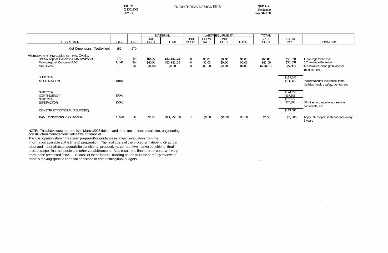
Alternative 4: 4" HMAC plus 5.5" PAC Overlay Hot Mix Asphalt Concrete (HMAC) w/FAAM Paving Asphalt Concrete (PAC) Misc. Detail
SUBTOTAL MOBILIZATION
SUBTOTAL CONTINGENCY SUBTOTAL SITE FACTOR
CONSTRUCTION TOTAL (ROUNDED)
O&M Replacment Costs -Annual
150
979 1,346
1
10.0%
30.0%
20.0%
4,500
270
0 $0.00 $0.00 $0.00 $55.00 $53,831 4' average thickness TN $55.00 $53,831.25
LS $0.00 $0.00 0 $0.00 $0.00 $0.00 $5,383.13 $53,831 5.5' average thickness $5,383 % allowance-clear, grub, anchor
TN $40.00 $53,831.25 0 $0.00 $0.00 $0.00 $40.00
trenches, etc
$1 13,046 $1 1,305 Includes bonds, insurance, temp
facilities, health, safety, demob, etc
$1 24.350 $37,305 $1 61,655 $37,305 40hr training, monitoring, security
$1 99,000 constraints, etc
SY $2.50 $1 1,250.00 0 $0.00 $0.00 $0.00 $2.50 $3,800 Apply PAC repair seal coat once every 3 years
NOTE: The above cost opinion is in March 2003 dollars and does not include escalation, engineering, construction management, sales tax, or financial. The cost opinion shown has been prepared for guidance in project evaluation from the information available at the time of preparation. The final costs of the project will depend on actual labor and material costs, actual site conditions, productivity, competitive market conditions, final project scope, final schedule and other variable factors. As a result, the final project costs will vary from those presented above. Because of these factors, funding needs must be carefully reviewed prior to making specific financial decisions or establishing final budgets. . . ..

431.02 01l30l2003 Rev. 11
UNIT UNIT CREW UNIT UNIT DESCRIPTION QTY UNIT COST TOTAL HOURS RATE COST TOTAL COST
ENGINEERING DESIGN FILE
TOTAL COST COMMENTS
EDF-3434 Revision 0
Page 35 of 50
MATERIAL LABOWEQUIPMENT
INEEL ICDF STAGING PILE
ORDER OF MAGNITUDE COST OPINION
TOTAL
DATE: 5/30/03 PROJECT NO.: ESTIMATE BY: D. HedglinlK. Sarnpaco
Alternative 5: 5.5" HMAC plus 12" Base Course Granular Base Course Hot Mix Asphalt Concrete (HMAC) Misc. Detail
SUBTOTAL MOBILIZATION
SUBTOTAL CO WING ENCY SUBTOTAL SITE FACTOR
CONSTRUCTION TOTAL (ROUNDED)
1,500 CY $1 5.00 $22,500.00 0.02 $447.46 $8.95 $13,423.68 $23.95 $35,924 1,346 TN $50.00 $67,289.06 0 $0.00 $0.00 $0.00 $50.00 $67,289 5.S average thickness
1 LS $0.00 $0.00 0 $0.00 $0.00 $0.00 $10,321.27 $1 0,321 % allowance-clear, grub, anchor trenches, etc
10.0%
30.0%
20.0%
$1 13.534 $1 1,353 Includes bonds, insurance, temp
facilities, health, safety, demob, etc
$1 24,887 $37.466 $1 62.354 $37,466 40hr training, monitoring, security
$200.000
constraints, etc
$3,800 Apply HMAC repair seal coat once SY $2.50 $1 1,250.00 0 $0.00 $0.00 $0.00 $2.50 4,500 every 3 years
O&M Replacment Costs -Annual
NOTE: The above cost opinion is in March 2003 dollars and does not include escalation, engineering, construction management, sales tax, or financial. The cost opinion shown has been prepared for guidance in project evaluatlon from the information available at the time of preparation. The final costs of the project will depend on actual labor and material costs, actual site conditions, productivity, competltive market conditions, final project scope, final schedule and other variable factors. As a result, the final project costs will vary from those presented above. Because of these factors, funding needs must be carefully reviewed prior to making specific financial decisions or establishing final budgets.

431.02 0 1 /30/2003 Rev. 11
TRADES' *. 1 Carpenter Cement Mason Electrician Fence Laborer Flagger Ironworker Laborer Pipe Layer Painter, . Plumber Oper-Heavy Oiler/Mechanic Teamster Welder
Excavation Foreman OperHeavy Oiler Ldorer
1 1 1 1 1 1 1 1 1 1 1 1 1 1
ENGINEERING DESIGN FILE
36.00 37.02 43.83 12.77 26.1 8 37.1 7 30.86 31.34 28.63 46.06 38.54 37.60 35.47 30.66
1.40 1.40 1.40 1.40 1.40
1.40 1.40 1.40. 1.40 I .40 1.40 1.40 1.40
1 . i5
1 39.54 39.54 1 38.54 38.54. 1 37.60 37.60 1 .30.86 30.86
146.54 Ti1 1.40
-- OH8P . 1.2
$246.1 9
1 39.54 39.541 _ _ 2 .38.54- - I 77.08. 0 37.60 0.00 . -
Laborer 3 30.86 92.58 209.20
,Tal 1.40, _. OH8P . 1.2
$351 -46
Pipe d, Manhole Foreman 1 37.00 ~ 37.00 Operator 1 36.00 36.00 Oiler 1 37.60 37.60 Laborer 3 30.86 92.58
203.1 8 T81 1.40
. _
-0HBP 1.2 $341.34
Load Foreman Operator Laborer
1 37.00 . . 37.00 1 36.00 36.00
73.00 0 . 30.86 0.00
1.40 Tbl OHBP 1.2
..- -
$1 22.64
Place tl Compact Foreman i 37.00 37.00 Operator 2 36.00 72.00 Laborer 1. 30.86 30.86
139.86 T81 1.40 OHBP . 1.2
$234.96
1.2 $60.48 1.2 $62.1 9 1.2 $73.63 1.2 $21 -45 1.2 $43.98 1.2 $62.45 1.2 $51 3 4 1.2 $52.65 1.2 $48.1 0 1.2 $77.38 1.2 $64.75 1.2 $63.1 7 1.2 $59.59 1.2 $51 .a4
EDF-3434 Revision 0
Page 36 of 50
Updated 8/31/02
PidUIp Trench Box ExcaMtDr
PiCkUp Roller
Dozerlloader
Pidurp h e
to& Pidurp
OH8P
R&p Dozer (21
10.00 0.00
80.00 90.00
1 -
$108.00 f
590.m 1.2
10.00 20.00
0.00 50.00 80.00
1.2 $96.00 $
10.00 $1 00.00
0.00 110.00
1.2
f132.00 s
$0.00 $80.00
10.00 $90.00
1.2 $1 08.00
10.00 $80.00
90.00 1.2
$lO8.00 $
354.19
441 A6
473.34
$230.64
342.96

431.02 01 /30/2003 Rev. 11
CREWS (continued) 1 Hauling Teamster
Misc Foreman Carpenter/Laborer
ENGINEERING DESIGN FILE
1 35.47 35.47 35.47
T8 I 1.40 OH8P 1.2
$59.59
1 37.00 37.00 1 36.00 36.00
73.00 T8 I 1.40 OH8P 1.2
$1 22.64
TNC~ 8 Trailer 45.00 45.00
OH8P
Misc
OH8P
EDF-3434 Revision 0
Page 37 of 50
1.2 $54.00 $ 11359
5.00 5.00
1.2 $6.00 $ 128.64
431.02 0 1 /30/2003 Rev. 11
ENGINEERING DESIGN FILE
This page is intentionally left blank.
EDF-3434 Revision 0
Page 38 of 50

431.02 01 /30/2003 Rev. 11
ENGINEERING DESIGN FILE EDF-3434 Revision 0
Page 39 of 50
Appendix B
Calculations

431.02 01130/2003 Rev. 11
ENGINEERING DESIGN FILE EDF-3434 Revision 0
Page 40 of 50
This page is intentionally left blank.

431.02 01/30/2003 Rev. 11
ENGINEERING DESIGN FILE
787.9 kPa
k r H - 125 mm (1' plrlkle a b } and mbrovldsd g r a d (MF. I 0.5)
EDF-3434 Revision 0
Page 41 of 50

431.02 01 /30/2OO3 Rev. 11
ENGINEERING DESIGN FILE EDF-3434 Revision 0
Page 42 of 50

SubJed: Geomernbrane Puncture ProtectIan (Geotexllle Cushlon) Calw Calca by K,L SampaccVCHPM HILL
30-
28 - 12 orlyd2 geoted8cr - angular rock - 26 -- I - - * - 12 Qrlyd2 geatextRe - 6UkWndsd rock - 24 -E+ 16 olr/yd2 geotextlle - angular rock - 22 - - xtilr-rukwnded rock -
-.-*---__I- - 20 --
E 18-
g 16 -.
8 Z 1 4 - Q 12 I
LL 10 - 8 -- 6 -.
4 -
2
0 - 0 0.5 1 i .ti 2 2.5

431.02 01 J3QMO03 Rev. 11
ENGINEERING DESIGN FILE EDF-3434 Revision 0
Page 44 of 50

431.02 01 130/2003 Rev. 11
ENGINEERING DESIGN FILE EDF-3434 Revision 0
Page 45 of 50
PROJECT NUMBER: SIIE~I OF&

431.02 01/30/2003 Rev. 11
ENGINEERING DESIGN FILE EDF-3434 Revision 0
Page 46 of 50

431.02 01/30/2003 Rev. 11
ENGINEERING DESIGN FILE EDF-3434 Revision 0
Page 41 of 50
I 1
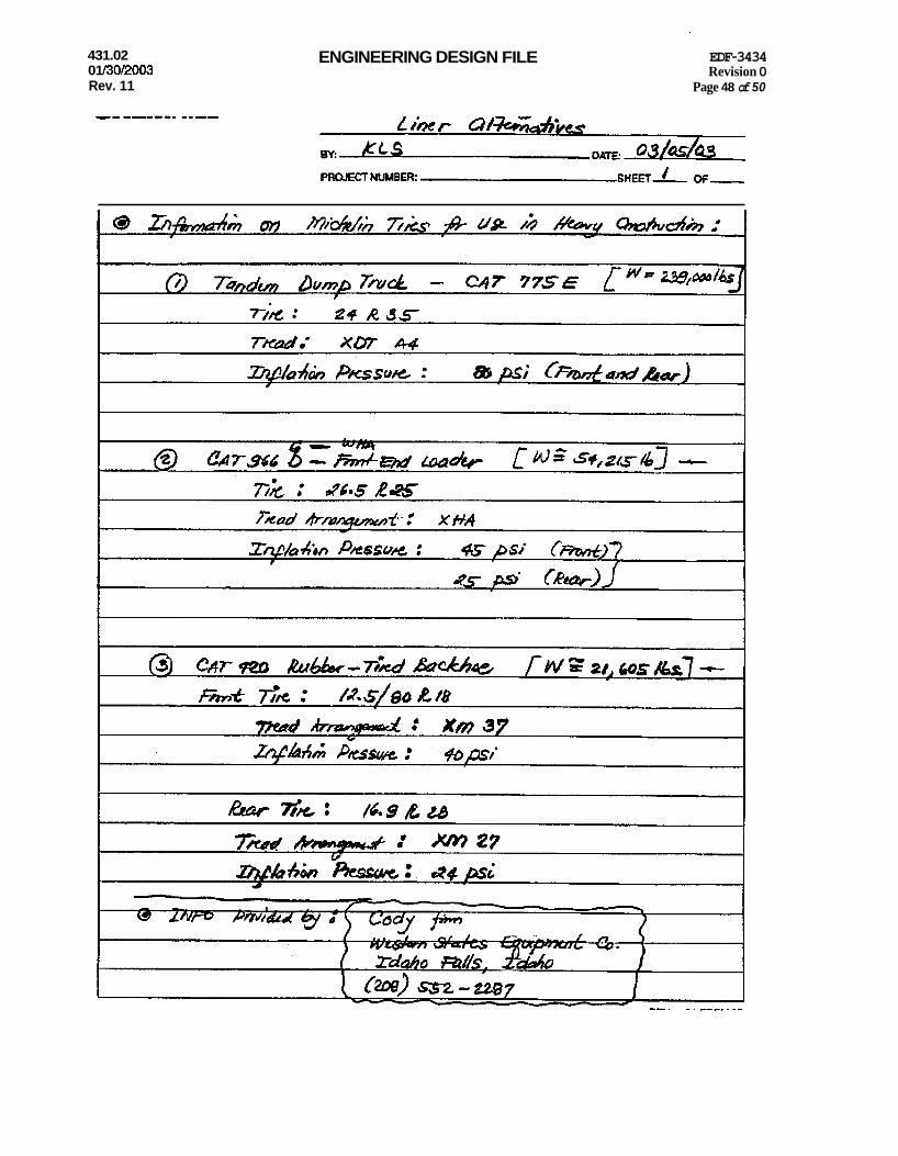
431.02 01 /30/2003 Rev. 11
ENGINEERING DESIGN FILE EDF-3434 Revision 0
Page 48 of 50

431.02 01 /30/2003 Rev. 11
ENGINEERING DESIGN FILE EDF-3434 Revision 0
Page 49 of 50
Msrch 7,2003
To: King Sarnpaa-CH2-L k: Dmve Strnng - Micbtlia EM Technical Snpport $abject: Coatact Area and Ground pressure
Here p f e mknIatSons of the reqaested information.
pres= Tireorrsspre Load Total contact area Gmund Pwssnr~ 265R25 45psi 13600 lbs 305 in2
45 psi 17500 Ibs 372 in2 25 Psi 9700 Ibs 382 in2
460 in2 25 psi 13600 lbs
24mR35 8opsi 37000 bs 605 'b2
12Rl65 35psi 1800 Ibs 58 in2 31 pd / j
l#RZ8 XM27 and 12.5l80Rl8 XM37 -These product8 belong to the
f*
MzFsr 41300 Ibs 639 in2
w ?ur244J
A g r h h r a I product he. I have requested cbe information. Hope to have the information by next week.
NOTE: AU figures above are calculatfons and are not verified by actual meamrements. The calcuhfioms will vpry with change in any of the fohving - (load, tire pressure road sadace, tcmperatme, machine type and use, load con~ration) . When using these calculations and safety Is an issue, always error on the si& of safety.

431.02 01 /30/2003 Rev. 11
ENGINEERING DESIGN FILE EDF-3434 Revision 0
Page 50 of 50
lexible Pavement Analysia
Structural maber 2.26 Design E 18's 525.000
Reliability 50. O D Overall Deviation I') 0 . 4 5
Soil Resilient Mod.(*) Initial Serviceabalaty T e r m i n a l Serviceability
-0lve FOX- Structural Number 2.26 -
Pgm FOR LAYER DBTEFWIBIATXON
4
FLEXIBLE P A W THICWTESS DETERMINATION -1 I
A d d f t i O M l Layer *) Drainage Layer Thickness
= = a [ i l = - m ( i ) - -t- - - 0 .42 2 -31 -0.12
Coefficient Coc€ficfcnt Thickness a ( i ) *Cd*c Needed
UNITS -- II -
- I I


![[PPT]What is t,n,m staging and summary staging? Staging for... · Web viewWhat are we discussing? What is AJCC Staging Purpose of staging General rules for clinical and pathological](https://img.dokumen.tips/doc/110x75/5b1cc7cc7f8b9a8c5a8ba42e/pptwhat-is-tnm-staging-and-summary-staging-staging-for-web-viewwhat.jpg)