Embed Size (px)
Citation preview
AlphaMidiCourseGyro Compass
Installation and Operation Manual
www.jrc.am
Contents
I Preface..........................................................................................................5I.1 Revision History........................................................................................................................................................ 5I.2 Points of Attention.....................................................................................................................................................5I.3 Glossary.................................................................................................................................................................... 6I.4 Storage...................................................................................................................................................................... 6
II Caution........................................................................................................ 7II.1 Warning Label.......................................................................................................................................................... 7II.2 Location Warning Label........................................................................................................................................... 7II.3 Cautions................................................................................................................................................................... 7
III Introduction..............................................................................................12III.1 Display and Alarm.................................................................................................................................................12III.2 Types of Alarm Function.......................................................................................................................................12III.3 Step Signal Type Repeater Signal Output Function.............................................................................................13III.4 Serial Signal Type Repeater Signal Output Function...........................................................................................13III.5 Automatic Speed Error Correction Function.........................................................................................................13III.6 Timer Start............................................................................................................................................................ 14III.7 Function of the External Heading Sensor............................................................................................................ 14III.8 Warranty Conditions..............................................................................................................................................14
1 Installation Instructions........................................................................... 151.1 Installation Guidelines............................................................................................................................................ 15
1.1.1 General and Specific Tools.......................................................................................................................... 151.1.2 Unpacking of the Gyro Compass................................................................................................................. 161.1.3 Fitting Master Compass Part 1.....................................................................................................................171.1.4 Fitting Master Compass Part 2.....................................................................................................................171.1.5 Remove Parts from Master Compass Mounting Ring.................................................................................. 181.1.6 Remove Packing Material from Shock Absorbers........................................................................................ 181.1.7 Unpacking of Sensitive Element Part 1........................................................................................................191.1.8 Unpacking of Sensitive Element part 2........................................................................................................ 191.1.9 Mounting of Sensitive Element Part 1.......................................................................................................... 201.1.10 Mounting of Sensitive Element Part 2........................................................................................................ 201.1.11 Filling with Damping Oil.............................................................................................................................. 211.1.12 Attach Connector.........................................................................................................................................21
1.2 Name and Function of Each Unit.......................................................................................................................... 221.3 Configuration.......................................................................................................................................................... 221.4 Mounting the Master Unit...................................................................................................................................... 231.5 Connecting the AlphaMidiCourse.......................................................................................................................... 241.6 Alarm List............................................................................................................................................................... 241.7 DIP Switch Settings............................................................................................................................................... 25
2 Operation...................................................................................................292.1 Operating panel......................................................................................................................................................292.2 Explanation of the Operating Panel.......................................................................................................................30
2.2.1 Steering Sensor Selection............................................................................................................................ 322.2.2 Setting of the Latitude Input......................................................................................................................... 32
2 | Contents

2.2.3 Setting of the Ship's Speed Input.................................................................................................................322.2.4 Setting of the Rate of Turn Filter Constant.................................................................................................. 33
2.3 Data Indications..................................................................................................................................................... 332.3.1 True Heading 1............................................................................................................................................. 332.3.2 True Heading 2............................................................................................................................................. 342.3.3 Master Heading.............................................................................................................................................342.3.4 Latitude..........................................................................................................................................................342.3.5 Ship Speed....................................................................................................................................................352.3.6 Rate of Turn..................................................................................................................................................352.3.7 Alarm Content............................................................................................................................................... 36
2.4 Start and Stop Sequence...................................................................................................................................... 362.5 Start and Running..................................................................................................................................................38
2.5.1 Start............................................................................................................................................................... 382.5.2 Set Timer Starting Time................................................................................................................................392.5.3 Set Start Heading..........................................................................................................................................392.5.4 Set Latitude Input System............................................................................................................................ 402.5.5 Synchronization of the Repeater Compass.................................................................................................. 412.5.6 Settling Time................................................................................................................................................. 422.5.7 Set Ship Speed Input System...................................................................................................................... 422.5.8 Set Rate of Turn Filter Constant.................................................................................................................. 432.5.9 Confirmation of True Heading.......................................................................................................................442.5.10 True Heading Indication..............................................................................................................................45
2.6 System Selection................................................................................................................................................... 452.7 Monitoring while Running.......................................................................................................................................45
2.7.1 Confirmation of Alarm Status........................................................................................................................462.7.2 Confirmation of Gyro Compass True Heading............................................................................................. 462.7.3 Confirmation of Latitude................................................................................................................................462.7.4 Confirmation of Ship Speed..........................................................................................................................46
2.8 Operation Procedure of Master Compass Power Switch (Option)........................................................................ 472.8.1 Operation Procedure.....................................................................................................................................472.8.2 Return Procedure..........................................................................................................................................47
2.9 Alarm...................................................................................................................................................................... 472.9.1 Alarm Content............................................................................................................................................... 482.9.2 Corrective Measures GPS Communication Failure...................................................................................... 512.9.3 Corrective Measures External Heading Sensor Communication Failure......................................................512.9.4 Corrective Measures LOG (serial signal) Communication Failure................................................................512.9.5 Corrective Measures LOG (contact) Failure.................................................................................................52
2.10 Turning the Gyro Compass OFF......................................................................................................................... 52
3 Specifications............................................................................................53
4 Maintenance.............................................................................................. 574.1 General Procedures............................................................................................................................................... 574.2 Periodical Checks.................................................................................................................................................. 584.3 Warning Label Check.............................................................................................................................................584.4 Spare Parts............................................................................................................................................................ 584.5 Disposal Method.................................................................................................................................................... 594.6 Troubleshooting......................................................................................................................................................59
4.6.1 General..........................................................................................................................................................594.6.2 Before Troubleshooting................................................................................................................................. 594.6.3 Corrective Measures..................................................................................................................................... 604.6.4 Corrective Measures when an Alarm is Activated........................................................................................604.6.5 Failure Phenomena and Corrective Measures............................................................................................. 60
4.6.5.1 Power Supply Failure (alarm code 1).................................................................................................. 604.6.5.2 Power Supply Failure (alarm code 2).................................................................................................. 614.6.5.3 Inverter Failure (alarm code 3)............................................................................................................ 614.6.5.4 Rotor Level Failure (alarm code 6)......................................................................................................614.6.5.5 Zero Cross Failure (alarm code 8)...................................................................................................... 61
3 | Contents

4.6.5.6 System Communication Failure (1) (alarm code A).............................................................................624.6.5.7 System Communication Failure (2) (alarm code b)............................................................................. 624.6.5.8 GPS Communication Stop (alarm code c) or Failure of GPS data (alarm code d).............................. 624.6.5.9 System Internal Communication Failure (1) (alarm code E) or System Internal Communication
Failure (2) (alarm code F)............................................................................................................................. 634.6.5.10 Master Compass Heading Failure (alarm code G)............................................................................ 634.6.5.11 External Heading Sensor Communication Stop (alarm code L) or External Heading Sensor Data
Failure (alarm code n)...................................................................................................................................634.6.5.12 LOG (serial signal) Communication Stop (alarm code P) or LOG (serial signal) Data Failure (alarm
code U).......................................................................................................................................................... 634.6.5.13 LOG Contact Failure (alarm code u)................................................................................................. 634.6.5.14 E5V Failure (alarm code r)................................................................................................................ 634.6.5.15 Gyro Compass does not Function, when Power Switch on the Operating Panel turned ON............. 644.6.5.16 Alarm is Activated at the Same Time when Power Switch Turned ON............................................. 644.6.5.17 Others.................................................................................................................................................644.6.5.18 When Failures cannot be fixed On Board......................................................................................... 64
4.6.6 Fuse Replacement........................................................................................................................................ 654.6.6.1 Master Compass (Inverter fuse F1).....................................................................................................66
5 Appendices................................................................................................675.1 Drawings.................................................................................................................................................................67
5.1.1 Outline Control Unit (One Gyro Compass System)......................................................................................685.1.2 Operating Panel............................................................................................................................................ 695.1.3 Master Compass........................................................................................................................................... 705.1.4 Stand Alone Type Control Unit of One Gyro Compass System...................................................................725.1.5 Connection Diagram......................................................................................................................................735.1.6 Cable Diagram.............................................................................................................................................. 745.1.7 Installation Drawing.......................................................................................................................................755.1.8 Terminal Board..............................................................................................................................................765.1.9 ITERM pwb................................................................................................................................................... 77
5.2 Periodic Check Tables...........................................................................................................................................775.2.1 Periodic Check Table 1................................................................................................................................ 785.2.2 Periodic Check Table 2................................................................................................................................ 795.2.3 Periodic Check Table 3................................................................................................................................ 80
5.3 Information to be supplied to Alphatron Marine.................................................................................................... 805.4 Accessories............................................................................................................................................................ 80
4 | Contents

I PrefaceThe AlphaMidiCourse Gyro compasses have been designated for any size of vessel to enhance the navigationcapabilities and reliability. The gyro compasses eliminate the inconvenience and limitations of magnetic compasses,and provide a variety of electrical outputs to supply accurate and consistent heading information to other navigationalequipment.
• The AlphaMidiCourse Compact gyro is designed for vessels with speeds of up to 50 knots.
• The AlphaMidiCourse complies with IMO A.424 (11) and Wheel Mark Specifications.
I.1 Revision History
Revision Nr. Description Date
V1.0 First Issue 19 February 2016
V1.1 Update Dip switch settings forHDT/THS
24 September 2018
I.2 Points of Attention1. Thoroughly read this instruction manual before installation and operation of the equipment.
2. We recommend to keep this manual nearby the equipment to ensure ready access to it. Assign a person in chargefor maintaining this manual in an assigned place.
3. Users of this manual are assumed to be qualified personnel according to governmental law for ship's officers, or thecorresponding laws.
4. Relevant drawings of the As Built plan of this system should be kept together.
5. Only qualified personnel as described above, or personnel under the supervision of a qualified person should operatethis system. Do not permit unqualified personnel operate this system.
6. If the manual is lost, request a new copy from ALPHATRON MARINE.
7. If labels become unreadable, or detached, request new ones from ALPHATRON MARINE.
5 | Preface

I.3 GlossaryThe meaning of standard definitions and terms as used in this manual are explained in the table of Definitions Table 1:Table of Definitions on page 6.
Definition Explanation
External Heading Sensor General term for the Heading Detection Sensor for Magnetic Compass System,Electronic Compass, GPS Compass, etc.
External Heading SensorSignal Processing Unit
Optional unit to this system. It enables to completely backup several circuits of therepeater signal (step signal / serial signal) by attachment of this unit when connected tothe external sensor.
Fixed Error Error between this system and keel line depending on the installation.
Last Azimuth This system can set and detect last azimuth of previous stop time. According to thisoperation, system settling time can be reduced when started the system again.
Leveling operation Operation to keep the sensor horizontal
Magnetic Compass System The heading detector is mounted on the magnetic compass and detected heading signalfrom the heading detector is sent out as repeater signal and serial signal.
Rate of Turn Speed of ship's turning
Sensitive Element Element to detect north of own ship
Speed Error Correction Gyro-compass generates error from the North depending on the speed and positionof ship's navigation. This system automatically calculates and corrects this error usingspeed and position data.
Step Signal Three phase signal with resolution of 1/6°. Voltage is 24 V standard. 70 V / 35 V outputcan be put out by expanding with the optional unit.
Table 1: Table of Definitions
I.4 StorageObserve the following items when storing:
1. Turn all power switches of this system to the OFF position to disconnect the power.
2. Storage temperature should be between –20℃ to +55℃.
3. Avoid a place with high humidity as much as possible.
4. Prevent the storage place from generating corrosive gas, breeding of bacteria such as mold or intrusion of insectsand small animals.
5. Cover the system with a plastic sheet, etc., when generation of dust is foreseen. When welding works, etc., arecarried out near this system, provide suitable protection to prevent damage caused by sparks, etc.
6 | Preface

II CautionTo safely install and operate this instrument, so as not to adversely affect the warranty, the WARNINGS and CAUTIONSmust be adhered to.
II.1 Warning LabelThe following warning label is attached to this system.
II.2 Location Warning LabelThe warning label is attached to the inside of the door of the Control Panel. See Figure 45: Stand alone type Control Unitof One Gyro Compass System on page 72
II.3 Cautions• WARNING - Clarification
• Indicates potential risk of injury or death to users of the product.
• WARNING - Operations
• Improper operations caused by failure of this product, or malfunctions caused by operator's misunderstandingmay cause collision or grounding and may result in property damage and environmental pollution. Also, deathor serious injury may happen.
• Full attention must be paid in the use of this product by understanding its limitations in performance andcharacteristics. Thoroughly familiarize yourself with the operation of this product.
• WARNING - Operations
• Carefully observe the CAUTIONS and WARNINGS prior to starting up and operating this product.
• Read the Operator Manual of the automatic steering system carefully and prepare for the occurrence oftrouble or alarm in this product. Ensure the emergency steering method is well understood to quickly respondto trouble.
• WARNING - Maintenance
• During maintenance or check of the product, touching internal parts may cause electric shock, becausethe ship's power supply is still connected to the system distribution board, even if the main power switch ofthis product is turned "OFF". Do not touch internal parts such as terminal boards, power supply unit, etc. Ifnecessary, disconnect the power cable from the ship’s distribution board. A warning label is attached to pointout this danger.
• WARNING
• Matters requiring attention in starting up and operations during progress are described in chapter Operationsand are punctuated with a CAUTION or a WARNING, which must be strictly observed.
• Attentively read the Operator Manual of the automatic steering system carefully preparing for occurrence oftrouble or alarm in this system. The emergency steering method should be well understood to easily respondto failures, or alarms.
• WARNING - Power Supply Failure (alarm code 1)
• Pay full attention to avoid electric shock when checking the power supply.
• When checking fuses, turn "OFF" the power switch on the operating panel and further disconnect the powercable from the ship’s distribution board before checking fuses.
7 | Caution

• WARNING - Inverter Failure (alarm code 3)
• When checking fuses, turn "OFF" the power switch on the operating panel and disconnect the power cablefrom the ship’s Distribution Terminal Board.
• WARNING
• When checking fuses, turn "OFF" the power switch, and further disconnect the power cable from the ship’sdistribution terminal board.
• CAUTION - Clarification
• Indicates potential risk of damage to equipment.
• CAUTION - Prohibition
• Do not use insulation tester or other device to test system insulation as it will damage internal electricalcomponents. Always disconnect the wiring connected to this system before testing related power distributionlines with such testers.
• CAUTION - General use
• This system displays Gyro Compass heading and outputs the heading information externally. Although thesafety design such as the alarm function against failure, etc., is provided, at the present time there is noperfect safety design. In addition, as this system has many important functions, it is hard to say that anyone can use this system without failure. Failures or malfunctions of this system may cause distress, andfull attention should be paid in using this product. The use of this equipment does not absolve the user'sresponsibility and obligation in practicing proper navigational techniques.
• Observe the following CAUTIONS:
• Always perform daily check to maintain normal system condition.
• When anomalies are detected as a result of daily checks, investigate and repair at once to restore to normalconditions and request advice from Alphatron service engineer.
• When the alarm system is activated during use, always check to confirm the cause and reinstate.
• CAUTION - Types of Alarm
• When an alarm regarding GPS (alarm code "c" or "d") is activated and the Gyro Compass' True Heading hasnot been determined, first turn the steering mode to "MANUAL", or "Non Follow Up", then determine the TrueHeading, because wrong heading information (repeater signal and serial signal) may be sent out.
• When an alarm regarding LOG (serial) (alarm code "P" or "U") is activated and the Gyro Compass' TrueHeading has not been determined, first turn the steering mode to "MANUAL" or "Non Follow Up", thendetermine the True Heading, because wrong heading information (repeater signal and serial signal) may besent out.
• When an alarm regarding LOG Contact (alarm code "u") is activated and the Gyro Compass' True Headinghas not been determined, first turn the steering mode to "MANUAL" or "Non Follow Up", then determine theTrue Heading because wrong heading information (repeater signal and serial signal) may be sent out.
• When an alarm regarding the EXTERNAL HEADING SENSOR (alarm code "E", "F", "L" and "N") is activated,the heading information immediately before the alarm was activated is sent. First turn the steering modeto "MANUAL" or "Non Follow Up", and then determine the true heading. Once True Heading has beendetermined, the system's heading is sent out.
• When the system is turned on, first turn the automatic steering system to "MANUAL" or "Non Follow Up" toprevent course turning with larger angle.
• CAUTION - Start Up
• Start up this product after turning the automatic steering system to other mode than "AUTO".
• CAUTION - Setting Latitude Input
• Change of the latitude input system, or a large change of latitude value may cause a large change in theTrue Heading. When on automatic steering, first turn the steering mode of the automatic steering system to"MANUAL" to prevent a large change of course. Confirm the area around the ship is clear and turn to "AUTO"steering again.
• CAUTION - Setting Latitude Input
• When an alarm regarding GPS (alarm code "c" or "d") is activated and the Gyro Compass' True Heading hasnot been determined, first turn the steering mode to "MANUAL", or "Non Follow Up", then determine the TrueHeading, because wrong heading information (repeater signal and serial signal) may be sent out.
8 | Caution

• CAUTION - Setting Latitude Input
• When "GYRO" is selected for the latitude input system, latitude is automatically updated by the ship's speedand the Gyro Compass True Heading. (When the ship's speed input system is "MANUAL", it is not updatedautomatically.) During navigation, confirm once every two hours that the ship's actual latitude coincides withthe indicated latitude.
• CAUTION - Setting Latitude Input
• Press ACK/ENT switch (4) to complete the setting. Changed setting is not updated unless pressing ACK/ENTswitch (4).
• CAUTION - Setting Speed Input
• Change of the ship's input system or large change of ship's speed may cause large change of the TrueHeading. When on automatic steering, first turn the steering mode of the automatic steering system to"MANUAL" to prevent a large course change. Confirm the area around the ship is clear and turn to "AUTO"steering again.
• CAUTION - Setting Speed Input
• When an alarm regarding GPS (alarm code "c" or "d") is activated and the Gyro Compass' True Heading hasnot been determined, first turn the steering mode to "MANUAL", or "Non Follow Up", then determine the TrueHeading, because wrong heading information (repeater signal and serial signal) may be sent out.
• CAUTION - Setting Speed Input
• When an alarm regarding LOG (serial) (alarm code "P" or "U") is activated and the Gyro Compass' TrueHeading has not been determined, first turn the steering mode to "MANUAL" or "Non Follow Up", thendetermine the True Heading, because wrong heading information (repeater signal and serial signal) may besent out.
• CAUTION - Setting Speed Input
• When an alarm regarding LOG contact (alarm code "u") is activated and the Gyro Compass' True Headinghas not been determined, first turn the steering mode to "MANUAL" or "Non Follow Up", then determine theTrue Heading, because wrong heading information (repeater signal and serial signal) may be sent out.
• CAUTION - Setting Speed Input
• The setting of the ship's speed input system (and its values for "MANUAL") is automatically saved. When re-starting, the previous ship's speed system setting is activated. When "MANUAL" is selected, stop after ship'sspeed setting is set to zero knots. Also, when turning off and on again with "GPS" selected, confirm that GPSis operating properly.
• CAUTION - Setting Speed Input
• Press ACK/ENT switch to complete the setting. Changed setting is not updated unless pressing ACK/ENTswitch.
• CAUTION - Setting "Rate of Turn Filter Constant"
• Press ACK/ENT switch to complete the setting. Changed setting is not updated unless pressing ACK/ENTswitch.
• CAUTION - Confirmation True Heading
• When the Gyro Compass' True Heading is set again, the repeater indication value and the serial signal GyroCompass True Heading will change by the altered angle. When on automatic steering, first turn the steeringmode of the automatic steering system to "MANUAL" to prevent a large course change. Confirm the areaaround the ship is clear and turn to "AUTO" steering again.
• CAUTION - Confirmation True Heading
• Press ACK/ENT switch to complete the setting. Changed setting is not updated unless pushing ACK/ENTswitch.
• CAUTION - System Selection
• System selection (switching) may cause a large change of True Heading. When on automatic steering, firstturn the steering mode of the automatic steering system to "MANUAL" to prevent a large course change.Confirm the area around the ship is clear and turn to "AUTO" steering again.
• CAUTION - Monitoring in Progress
9 | Caution

• Change of the ship's Speed Input System and the Latitude Input System, or large change of the ship's speedand latitude, may cause a large change of the Gyro Compass True Heading. When on automatic steering,first turn the steering mode of the automatic steering system to "MANUAL" to prevent a large course change.Confirm the area around the ship is clear and turn to "AUTO" steering again.
• CAUTION - Confirmation of Latitude
• Change of the latitude input system or large change of the latitude may cause a large change of TrueHeading. When on automatic steering, first turn the steering mode of the automatic steering system to"MANUAL" to prevent a large course change. Confirm the area around the ship is clear and turn to "AUTO"steering again.
• CAUTION - Confirmation of Ship Speed
• Change of the ship's speed input system or large change of the ship's speed may cause a large change ofTrue Heading. When on automatic steering, first turn the steering mode of the automatic steering system to"MANUAL" to prevent a large course change. Confirm the area around the ship is clear and turn to "AUTO"steering again.
• CAUTION - System Selection
• System selection (switching) may cause large change of True Heading. When on automatic steering, first turnthe steering mode of the automatic steering system to "MANUAL" to prevent a large course change. Confirmthe area around the ship is clear and turn to "AUTO" steering again.
• CAUTION - Operating Procedure Master Compass Switch (Option)
• DO NOT touch the Master Compass Power Switch while the Gyro Compass operates normally, to preventserious damage to the sensitive element, reduce the life cycle of the product, or unexpected problems. TheMaster Compass Power Switch must be operated only when the master compass is in abnormal condition.
• CAUTION - Alarms
• When the following alarms are activated, the heading information from this system may not be sent at all,or may have a large error. All units operated by the heading information from this system (in particular, theautomatic steering system, etc.) should be operated immediately according to the individual emergencyoperating procedure.
• CAUTION - Corrective Measures GPS Communication Failure
• When an alarm related to GPS (alarm code "c" or "d") is activated and the Gyro Compass' True Heading hasnot been determined, first turn the steering mode to "MANUAL", or "Non Follow Up", then determine the TrueHeading, because wrong heading information (repeater signal and serial signal) may be sent out.
• CAUTION - Corrective Measures GPS Communication Failure
• Determination of the True Heading may cause large change of sent heading information. During automaticnavigation, great care should be taken, because large course changes may have happened.
• CAUTION - Corrective Measures EXTERNAL HEADING SENSOR Communication Failure
• When an alarm regarding the EXTERNAL HEADING SENSOR (alarm code "E", "F", "L" and "N") is activated,the heading information (repeater signal and serial signal) immediately before the alarm generated is sent.First turn the steering mode to "MANUAL" or "Non Follow Up", and then determine the True Heading. OnceTrue Heading has been determined, the system's heading is sent out.
• CAUTION - Corrective Measures EXTERNAL HEADING SENSOR Communication Failure
• Determination of the True Heading may cause large change of sent heading information. During automaticnavigation, great care should be taken, because large course changes may have happened.
• CAUTION - Corrective Measures LOG Communication Failure
• When an alarm regarding LOG contact (alarm code "u") is activated and the Gyro Compass' True Headinghas not been determined, first turn the steering mode to "MANUAL" or "Non Follow Up", then determine theTrue Heading because wrong heading information (repeater signal and serial signal) may be sent externally.
• CAUTION - Corrective Measures LOG Communication Failure
• Determination of the True Heading may cause large change of sent heading information. During automaticnavigation, great care should be taken, because large course changes may have happened.
• CAUTION - Corrective Measures LOG Contact Communication Failure
10 | Caution

• When an alarm regarding LOG Contact (alarm code "u") is activated and the Gyro Compass' True Headinghas not been determined, first turn the steering mode to "MANUAL" or "Non Follow Up", then determine theTrue Heading because wrong heading information (repeater signal and serial signal) may be sent out.
• CAUTION - Troubleshooting
• When an alarm is activated, immediately confirm content of the activated alarm and take appropriatemeasures. ●When a failure has been activated, confirm area around the ship is clear to perform check andtake appropriate measures in non-hazardous sea area, stopping the ship as a rule.
• CAUTION - Corrective Measures
• Before checking and replacing of fuses, and disconnecting / connecting of each unit, connector, printedcircuit, terminal cable, turn "OFF" the power switch of the operating panel, and disconnect the power cablefrom the ship’s distribution board, etc. It may cause electric shock and failure if left in "ON" position.
• CAUTION - Failure Phenomena Corrective Measures
• Whenever the internal setting of the system is changed, follow instructions of the Alphatron Service Engineer.
• When another failure is activated than appeared in this clause, or a replaced fuse has blown again, turn"OFF" the power switch of the operating panel, disconnect the power cable from the ship’s distribution boardand request repair from an Alphatron Service Engineer.
• When a failure has occurred and it has not been repaired according to this clause, turn "OFF" the powerswitch of the operating panel and request an Alphatron Service Engineer to repair it on making a call to port.Even if it has been repaired, request an Alphatron Service Engineer to check it.
• CAUTION - Rotor Level Failure (alarm code 6)
• Turn OFF the power switch.
• CAUTION - Zero Cross Failure (alarm code 8)
• Determination of the Gyro Compass True Heading when alarm code 8 is activated, may cause a largechange of the True Heading. During automatic navigation, take great care, because a large course changemay have happened.
• CAUTION - Master Compass Heading Failure (alarm code G)
• When an alarm code G is activated, the Gyro Compass True Heading may have an error. New input of theTrue Heading may cause a large change of the True Heading. When on automatic navigation, first turn thesteering mode to "MANUAL", then determine the True Heading to prevent turning course with larger angle.Confirm area around ship is clear and turn to "AUTO" steering again.
• CAUTION - The Gyro Compass does not operate, when turned ON and the power switch on the operatingpanel is turned ON.
• Be aware of electric shock when checking the main power supply.
• When checking fuses, turn OFF the power switch on the operating panel and disconnect the power cablefrom the ship’s distribution board before checking fuses.
• CAUTION - Not all repeaters operate
• When checking fuses, turn OFF the power switch, and disconnect the power cable from the ship’s distributionterminal board.
• CAUTION - No repeaters operate
• When checking fuses, turn OFF the power switch, and disconnect the power cable from the ship’s distributionboard.
• CAUTION - Maintenance and check
• Main units of this system consist of electronic circuits of high reliability. If a failure occurs, perform the checkand maintenance as described in this chapter and correct the fault(s) to prevent further risk of failure and tomaintain the system's performance. Failure to carry this out, the detection of the failure sign will be delayedand may cause accidents such as collision or grounding.
11 | Caution

III IntroductionThis Gyro Compass provides increased Rate of Turn and a broad range of input/output signals.
• WARNING - Operations
• Improper operations caused by failure of this product, or malfunctions caused by operator's misunderstandingmay cause collision or grounding and may result in property damage and environmental pollution. Also, deathor serious injury may happen.
• Full attention must be paid in the use of this product by understanding its limitations in performance andcharacteristics. Thoroughly familiarize yourself with the operation of this product.
• CAUTION - General use
• This system displays Gyro Compass heading and outputs the heading information externally. Although thesafety design such as the alarm function against failure, etc., is provided, at the present time there is noperfect safety design. In addition, as this system has many important functions, it is hard to say that anyone can use this system without failure. Failures or malfunctions of this system may cause distress, andfull attention should be paid in using this product. The use of this equipment does not absolve the user'sresponsibility and obligation in practicing proper navigational techniques.
• Observe the following CAUTIONS:
• Always perform daily check to maintain normal system condition.
• When anomalies are detected as a result of daily checks, investigate and repair at once to restore to normalconditions and request advice from Alphatron service engineer.
• When the alarm system is activated during use, always check to confirm the cause and reinstate.
It has the following features:
1. Automatic speed error correction.
2. Digital signal processing conform International Standards IEC61162.
3. Long service life.
This system has been designed to build an I - System : One gyro compass system.
Depending on the output signal the following type is provided: Step type : System mainly uses the step signal (repeatersignal).
III.1 Display and AlarmFor navigational safety considerations, various indicators and indicator lamps required for the system's operation andalarm functions, have been built into the operating panel.
III.2 Types of Alarm FunctionAlarms can be related to:
• GPS (alarm code "c" or "d")
• LOG (serial) (alarm code "P" or "U")
• Log Contact (alarm code "u")
• EXTERNAL HEADING SENSOR (alarm code "E", "F", "L" and "N")
• System is switched
• CAUTION - Types of Alarm
• When an alarm regarding GPS (alarm code "c" or "d") is activated and the Gyro Compass' True Heading hasnot been determined, first turn the steering mode to "MANUAL", or "Non Follow Up", then determine the TrueHeading, because wrong heading information (repeater signal and serial signal) may be sent out.
• When an alarm regarding LOG (serial) (alarm code "P" or "U") is activated and the Gyro Compass' TrueHeading has not been determined, first turn the steering mode to "MANUAL" or "Non Follow Up", thendetermine the True Heading, because wrong heading information (repeater signal and serial signal) may besent out.
12 | Introduction

• When an alarm regarding LOG Contact (alarm code "u") is activated and the Gyro Compass' True Headinghas not been determined, first turn the steering mode to "MANUAL" or "Non Follow Up", then determine theTrue Heading because wrong heading information (repeater signal and serial signal) may be sent out.
• When an alarm regarding the EXTERNAL HEADING SENSOR (alarm code "E", "F", "L" and "N") is activated,the heading information immediately before the alarm was activated is sent. First turn the steering modeto "MANUAL" or "Non Follow Up", and then determine the true heading. Once True Heading has beendetermined, the system's heading is sent out.
• When the system is turned on, first turn the automatic steering system to "MANUAL" or "Non Follow Up" toprevent course turning with larger angle.
III.3 Step Signal Type Repeater Signal Output FunctionThis system can drive the ship's repeater by the step signal of the Gyro Compass. Even when the Gyro Compass isoperated by the emergency power supply, the connected repeater can be driven (Repeater backup function).
Note Refer to the As Built plan kept on board for details of the repeater.
When the external heading sensor signal is connected to this system (magnetic compass system, etc.), the repeateroperates as follows, when the system is switched, see System Selection on page 45:
• When "GYRO" is selected: The step signal is sent by the Gyro Compass True Heading.
• When "EXT" is selected: The step signal is sent by the True Heading of the external heading sensor.
III.4 Serial Signal Type Repeater Signal Output FunctionThis system can drive the ship's repeater by the serial signal of the Gyro Compass.
Even when the Gyro Compass is operated by the emergency power supply, the connected repeater can be driven(Repeater backup function)
When this system's serial signal is not used for the repeater, the following serial signals may be sent:
1. Output conformed to IEC61162-1 ed. 2
2. Output conformed to IEC61162-2
These signals can be individually set for each circuit.
Refer to the As Built plan kept on board for details of the repeater and the serial signal.
When the external heading sensor signal (the magnetic compass system, etc.) is connected to this system, the repeateroperates as follows, when the system is switched:
(Refer to System Selection on page 45, for system switching.)
• When "GYRO" is selected: The serial signal is sent by the Gyro Compass' True Heading.
• When "EXT" is selected: The serial signal is sent by the True Heading of the External Heading Sensor.
III.5 Automatic Speed Error Correction FunctionThis system has functions to calculate speed error, an inherent error to the Gyro Compass, and to correct itautomatically.
Required data of latitude and speed to calculate the speed error, are selected and entered into the individual systems of{"GYRO" / "GPS"} and {"LOG (contact signal)" / "LOG (serial signal)" / "GPS" / "MANUAL"}.
Note For the selection of latitude and ship's speed input system, operate according to Set Latitude Input Systemon page 40 andSet Ship Speed Input System on page 42 in chapter Operations.
When "GPS" is selected as the input system, the serial signal conform IEC61162-1 / IEC61162-1 ed. 2 is received.
When "LOG (serial signal)" is selected as the input system, the serial signal conform IEC61162 / IEC61162-1 ed. 2 isreceived.
Also, when other than "MANUAL" is selected as the input system, speed error correction can be performed in real time.
13 | Introduction
III.6 Timer StartThe Gyro Compass can be automatically started according to date and time set for the departure.
Note It can be set up to one month maximum.
For setting up the departure date and time, operate according to Set Timer Starting Time on page 39 in chapterOperations.
III.7 Function of the External Heading SensorWhen the external heading sensor signal (the magnetic compass system, etc.) is connected to the AlphaMidiCourse, therepeater signal (serial signal or step signal) can be sent from this system by using the external heading sensor.
Also when the processing unit for the external heading sensor signal is built into the AlphaMidiCourse as an option, therepeater signal (2 circuits for serial signal and 1 circuit for step signal) can be backed up by using the external headingsensor, even if the Gyro Compass stops.
Note For the system selection, refer to System Selection on page 45 chapter Operation.
III.8 Warranty ConditionsFor Warranty Conditions contact Alphatron Marine.
14 | Introduction

1 Installation InstructionsThis chapter explains the configuration, specifications and structure of this system.
1.1 Installation GuidelinesMaster Compass
1. Select a mounting location where the deck is horizontal, flat, has little vibration and pitch/roll is as small as possible.
Note Mounting location should have sufficient space for installation and servicing. Refer dimensionaldrawing Figure 48: Installation Drawing on page 75.
2. Position the compass on or parallel to the vessel's horizontal center line, with the bow indication on the top of thecase pointing towards the vessel's bow.
3. Use the datum line in the front and back of the compass to line up the unit.
Note be sure to install all equipment cables more than 5m away from radio equipment feeders.
4.Connect terminals marked with the ground terminals of the vessel.
Note Shielded end of shielded cable to be finished close to the terminal board and connect to the groundterminals of the vessel.
5. Do NOT use a megger for any tests!
6. Ensure sufficient servicing space around the gyro compass. Refer dimensional drawing Figure 48: InstallationDrawing on page 75.
1.1.1 General and Specific ToolsGeneral and Specific tools are required for installing the Gyro Sphere into the Master Compass, as shown in pictureslabeled 001, 002 and 003.
Figure 1: Special and Specific Tools
15 | Installation Instructions
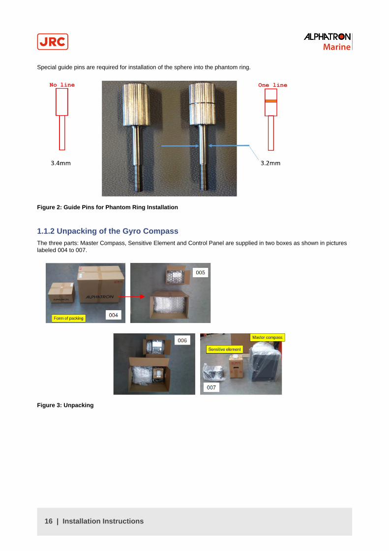
Special guide pins are required for installation of the sphere into the phantom ring.
Figure 2: Guide Pins for Phantom Ring Installation
1.1.2 Unpacking of the Gyro CompassThe three parts: Master Compass, Sensitive Element and Control Panel are supplied in two boxes as shown in pictureslabeled 004 to 007.
Figure 3: Unpacking
16 | Installation Instructions

1.1.3 Fitting Master Compass Part 1Fitting the Master Compass part 1, as shown in pictures labeled 008 to 011.
Figure 4: Fitting master Compass Part 1
1.1.4 Fitting Master Compass Part 2Fitting the Master Compass part 2, as shown in pictures labeled 012 and 013.
Figure 5: Fitting Master Compass Part 2
17 | Installation Instructions

1.1.5 Remove Parts from Master Compass Mounting RingRemove parts from Master Compass mounting ring as shown in pictures labeled 014 to 018.
Figure 6: Remove parts
1.1.6 Remove Packing Material from Shock AbsorbersRemove packing material from shock absorbers as shown in pictures labeled 019 to 021.
Figure 7: Remove Packing Material Shock Absorbers
18 | Installation Instructions
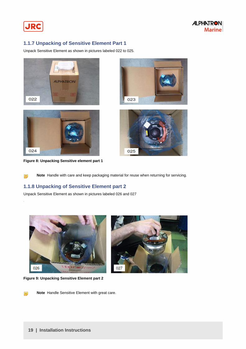
1.1.7 Unpacking of Sensitive Element Part 1Unpack Sensitive Element as shown in pictures labeled 022 to 025.
Figure 8: Unpacking Sensitive element part 1
Note Handle with care and keep packaging material for reuse when returning for servicing.
1.1.8 Unpacking of Sensitive Element part 2Unpack Sensitive Element as shown in pictures labeled 026 and 027
Figure 9: Unpacking Sensitive Element part 2
Note Handle Sensitive Element with great care.
19 | Installation Instructions

1.1.9 Mounting of Sensitive Element Part 1Mount the Sensitive Element as shown in pictures labeled 028 to 031.
Figure 10: Mounting of Sensitive Element part 1
1.1.10 Mounting of Sensitive Element Part 2Mount the Sensitive Element as shown in pictures labeled 032 to 034.
Figure 11: Mounting of Sensitive Element part 2
20 | Installation Instructions

1.1.11 Filling with Damping OilFill up container with Damping Oil as shown in pictures labeled 037 to 039.
Figure 12: Filling with Damping Oil
1.1.12 Attach ConnectorAttach Connector and fix securely to Sensitive Element as shown in pictures below.
Figure 13: Attach Connector
21 | Installation Instructions

1.2 Name and Function of Each UnitNames and functions of each unit.
No. Name Function
1. Master compass The sensitive element is built-in. It is a unit to detect the ship's heading.
2. Control Unit This unit has various indicators for True Heading, Latitude, Rate of Turn, ShipSpeed and Alarms, and the operating switches.
3. Indicators It indicates operating conditions of this system and value data of all settings valuedata. Indicated contents can be selected by operating the switches.
4. Operating switches They are used for all kinds of operations required for this system.
Power switch It is used to start and stop this system. The indicator lamp in the power switchalights when started.
Table 2: Name and function
1.3 Configuration
Figure 14: System Configuration
This system consists of the following units and the spare parts box.
1. Master Compass
2. Control Unit
3. Spare Parts box
For shipment, the sensitive element in the master compass is packed separately.
22 | Installation Instructions

1.4 Mounting the Master UnitMounting of the master compass unit is as shown in Figure 15: Mounting position on page 23.
Figure 15: Mounting position
Figure 16: Inverter Unit Location
1. Orientate the Inverter Unit at the back of the Master Compass to the Stern of the ship.
Note Install the Gyro Compass with in 5˚ accuracy in order to be able to apply a correction by loosening thefastening bolts and fine tune placement by turning the Mater Compass.
2. Fasten the compass to the deck with the four bolts provided.
Note Locate the bolts in the center of the trails to be able to finely adjust the direction of the unit. With the aidof the heading offset feature a small mounting offset may be made.
23 | Installation Instructions

1.5 Connecting the AlphaMidiCourseRefer Connection Diagram and Cable Diagram for cable connections Figure 46: Connection Diagram on page 73,Figure 47: Cable Diagram on page 74.
1. Connect power and signaling cables as indicated in the connection diagram.
2. Use wire straps to fasten cables.
CABLE SPECIFICATIONS - See Connection Diagram and Cable Diagram Figure 46: Connection Diagram on page73, Figure 47: Cable Diagram on page 74.
1.6 Alarm List
AlarmCode
Alarm Content Possible Cause
1 Main power is abnormal When the main power (AC power source) was lost.
2 Power is abnormal When the power supply in the control unit went over-voltage or over-current.
3 Inverter is abnormal When the inverter in the master compass went over-voltage or over-current.
6 Rotor level is abnormal When the "rotor” (Sensitive Element) in the Master Compass behavesabnormally.
8 Zero cross is abnormal When the reference heading of the master compass was not detected properlyor an failure is generated in heading calculation.
A System communication failure(1)
When a failure is generated in communication function of the master compass.
b System communication failure(2)
When a failure is generated in communication function of the control unit.
c GPS communication break When GPS operation stopped or the serial signal from GPS has stopped.
d Abnormality of GPS data When a failure is generated in the serial signal from the GPS.
E System internalcommunication failure (1)
When the External Heading Sensor Signal Processing Unit stopped itsoperation, or the serial signal from the External Heading Sensor ProcessingUnit has stopped.
F System internalcommunication failure (2)
When a failure is generated in the serial signal from the External headingsensor signal processing unit.
G Master compass headingfailure
When a failure is generated in the heading monitor signal of the mastercompass.
L External heading sensorcommunication off
When the External heading sensor signal processing unit stopped its operation,or the serial signal of the external sensor has stopped.
n External heading Sensor datafailure
When a failure is generated in the serial signal from the External headingsensor.
P LOG (serial) communicationoff
When the LOG stopped its operation, or the serial signal from LOG hasstopped.
U LOG (serial) data failure When a failure is generated in the serial signal from LOG.
u LOG contact failure When a failure is generated in the LOG contact.
r E5V failure When a failure is generated in the power supply for the serial signal.
Table 3:
24 | Installation Instructions
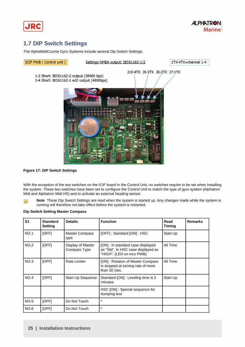
1.7 DIP Switch SettingsThe AlphaMidiCourse Gyro Systems include several Dip Switch Settings.
Figure 17: DIP Switch Settings
With the exception of the two switches on the ICIF board in the Control Unit, no switches require to be set when installingthe system. These two switches have been set to configure the Control Unit to match the type of gyro system (AlphatronMidi and Alphatron Midi HS) and to activate an external heading sensor.
Note These Dip Switch Settings are read when the system is started up. Any changes made while the system isrunning will therefore not take effect before the system is restarted.
Dip Switch Setting Master Compass
S1 StandardSetting
Details Function ReadTiming
Remarks
NO.1 [OFF] Master Compasstype
[OFF] : Standard [ON] : HSC Start Up
NO.2 [OFF] Display of MasterCompass Type
[ON] : In standard case displayedas "Std". In HSC case displayed as"HIGH". (LED on mcc PWB)
All Time
NO.3 [OFF] Rate Limiter [ON] : Rotation of Master Compassis stopped at turning rate of morethan 30˚/sec.
All Time
NO.4 [OFF] Start Up Sequence Standard [ON] : Leveling time is 2minutes
Start Up
HSC [ON] : Special sequence fordumping test
NO.5 [OFF] Do Not Touch *
NO.6 [OFF] Do Not Touch *
25 | Installation Instructions

S1 StandardSetting
Details Function ReadTiming
Remarks
NO.7 [OFF] Master CompassInstallation
[ON] : Master Compass is installedreversely 180˚
Start Up
NO.8 [OFF] Do Not Touch *
Table 4: MCC pwb switch assign
* For MCC pwb check mode : S1 all [ON].
Interval Setting NMEA: 100msec, or 200msec, or 1sec.¹ Set standard to off, for Pendulum Ferry use externalInterface!
ICIFpwb S1
StandardSetting
Details Function ReadTiming
Remarks
NO.1 [ON] Connect ExternalPower Supply Unit
[OFF] :yes [ON:no
Start Up
NO.2 [OFF] Master Compasstype
[OFF] : StandardType [ON] : HSCtype
Start Up
NO.3 [OFF] Control Box type [OFF] : Type S[ON] : Type D(dual gyro)
Start Up
NO.4 [OFF] No.2 Gyro or not [OFF] : No [ON] :Yes
Start Up
NO.5 [OFF]
NO.6 [OFF]External SensorConnection
NO5.[OFF],NO6.[OFF] : Non
NO5. [ON],NO6. [OFF] :External SensorConnection
Start Up
NO.7 [OFF] Serial Signal Select [OFF] :IEC61162-2[on] : Tokimecformat
Start Up
NO.8 [OFF] Alarm OutputSetup
[OFF] : All alarmoutput [ON] :only power fail
Start Up
Table 5: ICIF PWB Dip Switch assign :
ICIFpwb S2
StandardSetting
Details Function ReadTiming
Remarks
NO.1 [OFF] For debugging (DoNot Touch)
-
NO.2 [OFF] For debugging (DoNot Touch)
-
NO.3 [ON[ Alphatron or other [OFF] : Standard [ON] :AlphaMidiCourse¹
NO.4 [OFF] Pendulum Ferry [OFF] : No [ON] : Yes Start Up
26 | Installation Instructions

ICIFpwb S2
StandardSetting
Details Function ReadTiming
Remarks
NO.5 [OFF] NO5.[OFF] NO6.[OFF] ; 1sec
NO5.[ON] NO6.[OFF] ; 200msec
NO.6 [OFF]
Serial SignalTransmitFrequencyIEC61162-1 ed.2
NO5.[OFF] NO6.[ON] ; 100msec
NO5.[ON] NO6.[ON] ; Invalid(1sec)
Start Up
NO.7 [OFF] Do Not Touch -
NO.8 [OFF] System SelectInformationContact
[OFF] : no [ON] : yes Start Up
¹ Standard set to off, for pendulum ferry use external interface!
ICIFpwb S3
StandardSetting
Details Function ReadTiming
Remarks
NO.1 [OFF] Timer Start Up [OFF] : no [ON] : yes Start Up
NO.2 [OFF] Talker ID of "ROT"Sentence
[OFF] : "HE" [ON] : "TI" Start Up
NO.3 [OFF] NO3.[OFF],NO4.[OFF] : Max30.0˚/min.
[NO3.[ON] NO4.[OFF] : Max300.0˚/min
NO.4 [OFF]
Rate of Turn Scalefor Analog meter NO3.[OFF],
NO4.[ON] : Max300.0˚/min.
[NO3.[ON] NO4.[OFF] : Do NotSet
Start Up
Valid at time of external sensor(standard) selection
NO.5 [OFF] Ban or permissionof an "RoT"Sentence Output
[OFF] : disable [ON] : enable
Start Up
NO.6 [ON] Alphatron or other [OFF] :no [ON] : AlphaMidiCourse Start Up
NO.7 [OFF] Unit check mode [OFF] : no [ON] : yes for factoryinspection only
Start Up
NO.8 [OFF] Buzzer stopcontact output
[OFF] : no [ON] : yes Start Up
IOPTpwb
StandardSetting
Details Function ReadTuning
Remarks
NO.1 [OFF] Do Not Touch -
NO.2 [OFF] For AGI-80 or not [OFF] : For normal TG-8000/8500[ON] : For AGI-80
Start Up
NO.3 [OFF] Able/Disable forHDG sentenceoutput
[OFF] : Able to output [ON] : Disableto output
Start Up
Alarm detectiontime for mainpower
Start UpNO.4 [OFF]
Fail / Power Unitfail
[OFF] : 300ms [ON] : 2sec
27 | Installation Instructions
IOPTpwb
StandardSetting
Details Function ReadTuning
Remarks
NO.5 [OFF] HDT / THSsentence
[OFF] : HDT [ON] : THS Start Up
NO.6 [OFF] Do Not Touch -
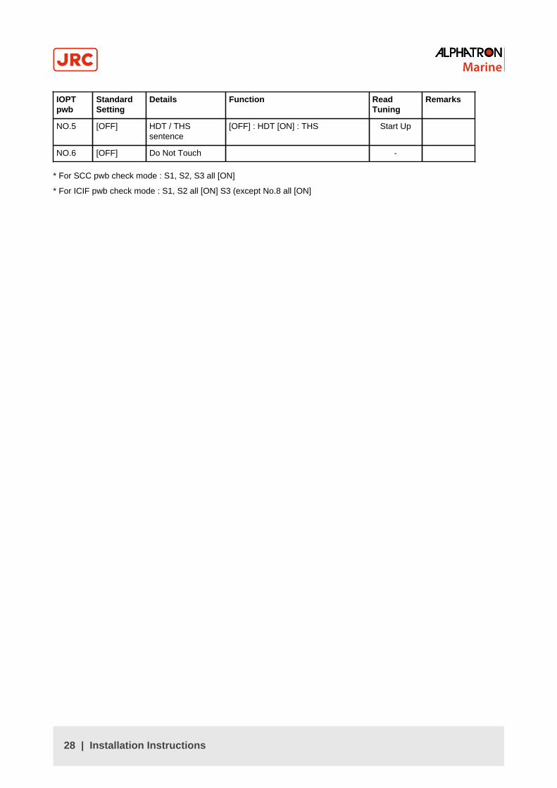
* For SCC pwb check mode : S1, S2, S3 all [ON]
* For ICIF pwb check mode : S1, S2 all [ON] S3 (except No.8 all [ON]
28 | Installation Instructions
2 OperationIn this chapter, procedure of operation, starting and stopping of this system are explained. Before operation, confirm thateach unit of the master compass and the control unit are properly installed.
• WARNING
• Matters requiring attention in starting up and operations during progress are described in chapter Operationsand are punctuated with a CAUTION or a WARNING, which must be strictly observed.
• Attentively read the Operator Manual of the automatic steering system carefully preparing for occurrence oftrouble or alarm in this system. The emergency steering method should be well understood to easily respondto failures, or alarms.
For the automatic steering system, carefully read the related Operator Manual in separate volume supplied by themanufacturer and perform appropriate preparation and handling before its operations.
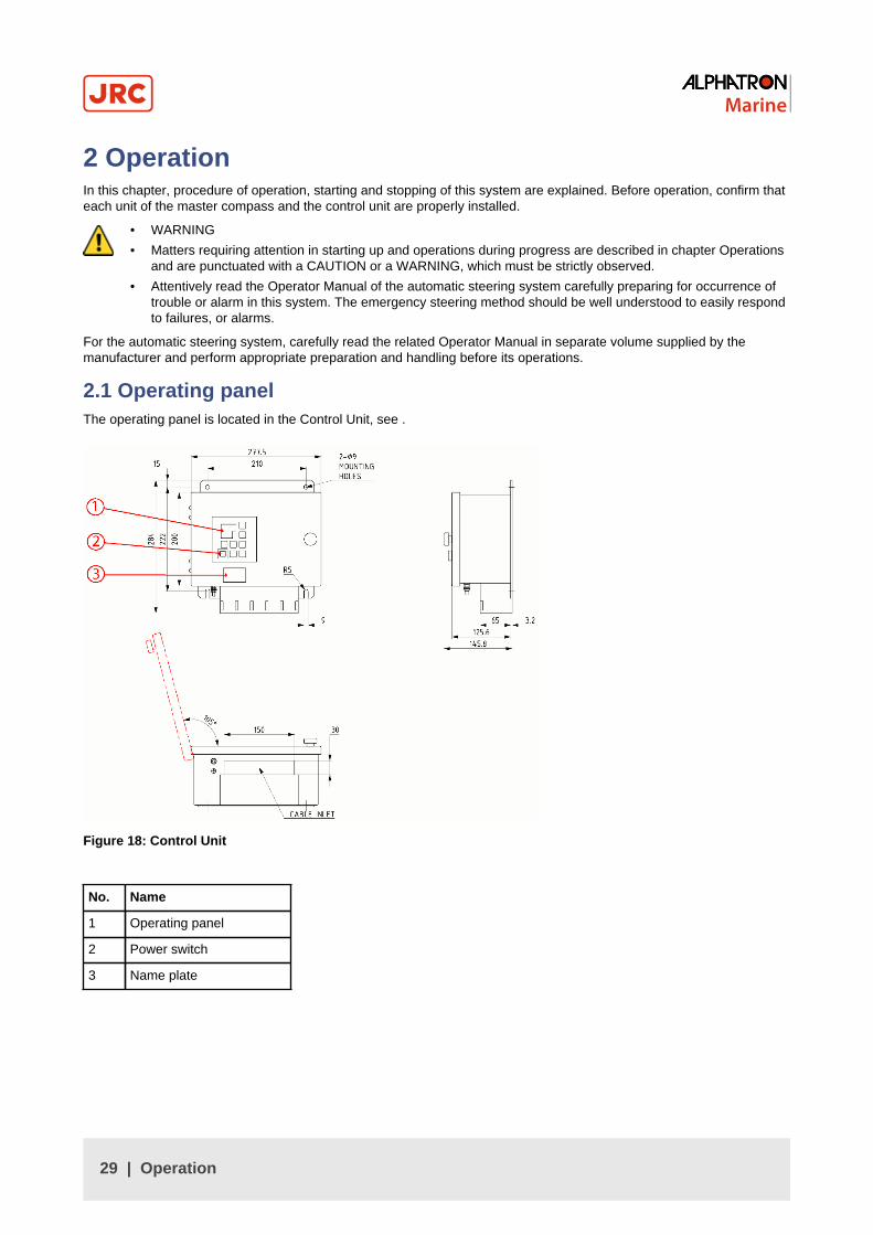
2.1 Operating panelThe operating panel is located in the Control Unit, see .
Figure 18: Control Unit
No. Name
1 Operating panel
2 Power switch
3 Name plate
29 | Operation

2.2 Explanation of the Operating Panel
Figure 19: Operating Panel
POWER switch Power switch / Power indicator
1. Open cover
2. Press to start/stop system
3. Close cover after start-up, so as not to inadvertently push the button.
DISP switch Select the displayed item and the displayed data.
1. Press to display data in order.
2. Press DISP and ACK/ENT simultaneously to display data in reverse order.
3. Refer Data and Mode Display for displayed text.
SET switch Change data and change the input system.
• Change data: Gyro Compass True Heading / Ship Speed / Latitude / Rate of Turn.
• Change input system: ¹ Ship Speed (MANUAL, GPS, LOG and LOG (serial signal))Latitude (GYRO and GPS).
ACK/ENT switch Determines the changed data and the changed input system.
Press to stop alarm buzzer when an alarm has been activated.
▲▼ switches Change data and change the input system.
Normally these are used to adjust illumination of the indicator.
1. Press ▲ for brighter.
2. Press ▲ for darker.
3. Press simultaneously for lamp test.
4. Data Display, the Mode Display and all lamps light up and it buzzes during the lamp test.
30 | Operation

GYRO switch System selection switch (Gyro).
1. Press to select required system.
2. "GYRO" system is select.
3. For system selection, refer to System Selection on page 45
EXT switch System selection switch (External).
1. Press to select required system.
2. "External Heading Sensor" system is selected.
3. For the system select, refer to System Selection on page 45
Data Display 4 figures, 7 segments red LED : Data is displayed. (Figure 42: Operating Panel on page69)
Mode Display 3 figures, 7 segments green LED: Type of data is displayed. (Figure 42: Operating Panel onpage 69)
Note When the rotor is in stopped situation, the dot at right end of the modeindicator is lit.
Note When the rotor is running, it is blinking.
Note When in the follow up situation, it is extinguished.
Alarm Indicator Displays alarm status. It blinks when an alarm is generated.
1. Press ACK/ENT to stop alarm.
2. If cause of alarm has not been resolved, it continues blinking.
System select Indicator Displays selected system.
Table 6: Functions Operating Panel
Note ¹ Selectable system is different depending on the system type connected to this system.
Explanation of Display:
PressDISP
1 True Bearing 1: ***
***.*
S.S.G or S.S.E or GYt
S.S.G = Steering.Sensor.Gyro-compass
S.S.E = Steering.Sensor.External sensor
Gyt
31 | Operation

2 True Bearing 2: ***
***.*
ESt or GYt
ESt = External Sensor true bearing
GYt = Gyro-compass true bearing
3 Master Compass Bearing:
***.*
C.P.S
C.P.S. = Compass
4 Latitude: ***.*
***.*
LA.n or LA.S
LA.n = Latitude North
LA.S = Latitude South
5 Ship's speed: ***.*
***.*
G.Sd or H.Sd or L.Sd or S.Sd
G.Sd = Gps.Speed
H.Sd = Hand.Speed
L.Sd = Log.Speed
S.Sd = Serial.Log.Speed
6 Rate of turn: ***.* rt. = Rate of turn
****
rt.
7 Alarm content:
****
Err
Err = Error
Table 7: Data / Mode Menu Structure
2.2.1 Steering Sensor Selection
1. Press the GYRO button to select the Gyro Compass and press ACK/ENT.
2. Press the EXT button to select the External Heading Sensor and press ACK/ENT.
2.2.2 Setting of the Latitude Input
1. Press the SET button.
2. Press ▼or▲ to select either GPS or GYro.
3. Press ACK/ENT to enter selection.
Note When H.Sd (MANUAL) was selected, as the latitude is displayed in the Data Indicator, press ▼or▲ toset the latitude and press ACK/ENT again. The herein after calculated latitude by the ship's speed and theTrue bearing is indicated by using the manually entered latitude.
2.2.3 Setting of the Ship's Speed Input
1. Press the SET button and use ▼or▲ to select one of the following modes: G.Sd (GPS), H.Sd (MANUAL), l.sD (LOGPULSE), or S.Sd (LOG SERIAL).
2. Press ACK/ENT to enter selection.
32 | Operation

2.2.4 Setting of the Rate of Turn Filter Constant
1. Press the SET button when the Rate of Turn Filter Constant is changed.
2. Press ▼or▲ to select the Filter Constant.
Note The Filter Constant can be set to 0.5, 1 or 2 through to 10 in 2second steps.
3. Press ACK/ENT to enter the selection.
2.3 Data IndicationsExplanations of indicated data.
2.3.1 True Heading 1When True Heading of the sensor is selected as system, either the Gyro Compass True Heading or the external headingsensor True Heading, is displayed. For the system selection, refer to System Selection on page 45
The indicated data in the data and mode indicators are shown in table below.
SystemSelection
Heading DataIndicator
Mode Indicator
Gyro 123.4 123.4
Heading 345.6 345.6
Table 8: Data and Mode Indicators True Heading 1
Note The meaning of a display of a “mode indicator” is as follows:
Figure 20: S.S.G = Steering Sensor Gyro Compass
Figure 21: Gyt = Gyro Compass true heading
Note When a GPS communication failure, LOG (serial signal) communication failure, or LOG (contact) failureis generated, the data indicator is blinking. If "GYRO" system is selected at the time, operate according toCorrective Measures GPS Communication Failure on page 51 is activated, Corrective Measures LOG (serialsignal) Communication Failure on page 51 is activated, or Corrective Measures LOG (contact) Failure onpage 52 is activated, in chapter Operations, because the True Heading determination is required.
Note When communication failure with "the external heading sensor" is generated, the data indicator is blinking.If "External heading sensor" system is selected at the time, operate according to Corrective Measures ExternalHeading Sensor Communication Failure on page 51 is activated, because the True Heading determination isrequired.
33 | Operation
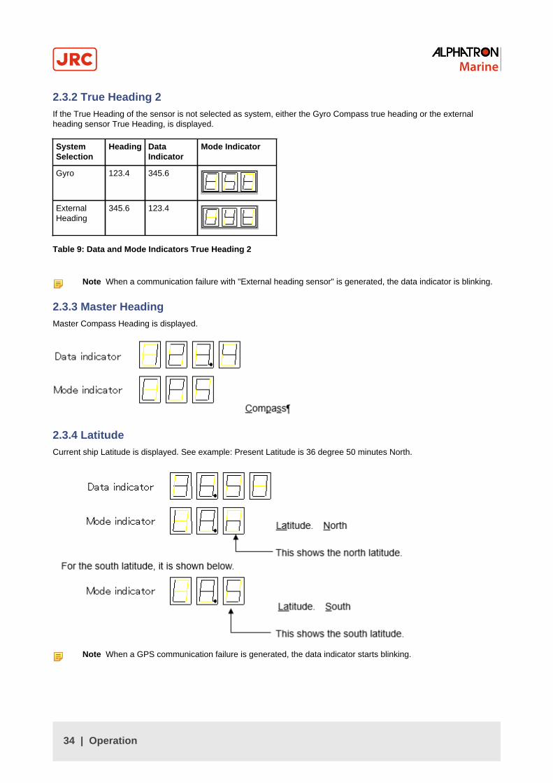
2.3.2 True Heading 2If the True Heading of the sensor is not selected as system, either the Gyro Compass true heading or the externalheading sensor True Heading, is displayed.
SystemSelection
Heading DataIndicator
Mode Indicator
Gyro 123.4 345.6
ExternalHeading
345.6 123.4
Table 9: Data and Mode Indicators True Heading 2
Note When a communication failure with "External heading sensor" is generated, the data indicator is blinking.
2.3.3 Master HeadingMaster Compass Heading is displayed.
2.3.4 LatitudeCurrent ship Latitude is displayed. See example: Present Latitude is 36 degree 50 minutes North.
Note When a GPS communication failure is generated, the data indicator starts blinking.
34 | Operation

2.3.5 Ship SpeedCurrent Ship Speed is displayed. See example: Present Speed input system is "GPS".
Note When a GPS communication failure is generated, the data indicator starts blinking.
Note When a LOG (contact) failure is generated, the data indicator starts blinking.
Note When a LOG (serial) failure is generated, the data indicator starts blinking.
2.3.6 Rate of TurnCurrent ship's turn rate is displayed. Unit of the indicated Rate of Turn is in degrees / minutes. See example: Presentlyright turn with 30 degrees / 0 minutes.
Note The Data indicator shows bar indication (blinking) until the master Gyro Compass starts to follow up, orwhen "External heading sensor" system is selected.
Note When the ship makes a left turn, the Mode indicator shows a minus sign (-), which is indicated in the farright space.
35 | Operation

2.3.7 Alarm ContentAn alarm activated in the Gyro Compass is displayed by an alarm code. For the alarm code indication, refer to Alarm onpage 47.
When there are no alarms, the display indication is as shown:
When an alarm is activated the display indication is as shown.
Alarms are displayed in the data indicator in the activated order from the left as shown below.
See example: Presently alarms with code 1, 2 and 3 were activated in order.
When 4 alarm codes are displayed at the same time and the dot in fourth place is not present, means more than 5alarms were activated.
Example: When alarms of alarm code 1, 2, 3, c and d were activated in order.
In this case, not-indicated alarm code can be confirmed by pressing ▲ switch as shown below.
To return to the previous indication, press ▼.
2.4 Start and Stop SequenceThis system operates in the sequence shown in the diagram
For each operation in the sequence, refer to Start and Running on page 38 and Turning the Gyro Compass OFF onpage 52.
1. Starting
36 | Operation

2. Setting (after start-up)
• Latitude setting: Confirm the latitude indication and set again if necessary.
• Speed setting: Confirm the speed indication and set again if necessary.
• Repeater synchronization: Synchronize each repeater.
3. Setting (Just before departure, or 6 hours or more after starting)
• Item 2 above: Reconfirm.
• Heading error correction: Fixed error can be corrected in output heading if necessary.
4. Alarm
If any alarm is activated, check the alarm code and press ACK/ENT switch.
5. System selection( Gyro-compass to be selected normally)
37 | Operation

System selection (switching) may cause large change of the True Heading.
1. During automatic steering, first turn the steering mode of the automatic steering system to "MANUAL" to preventlarge change of course.
2. Confirm surrounding area of ship is clear and turn to "AUTO" steering again.
• Select the Gyro Compass: While pressing ACK/ENT switch press GYRO switch.
• Select the external heading sensor: While pressing ACK/ENT switch press GYRO switch.
Repeater synchronization: Synchronize the each repeater indication with the selected True Headinginformation¹.
Note ¹ When repeater is a serial signal type, this operation is not required because it will synchronizeautomatically. However, confirm that the indicated value coincides with "the True Heading" selectedby this system after the repeater switch is turned "ON".
6. Stop
Turn each repeater switch to OFF and turn the Power Switch on the Gyro Compass operation panel to OFF. TheGyro Compass stops.
2.5 Start and Running• CAUTION - Start Up
• Start up this product after turning the automatic steering system to other mode than "AUTO".
2.5.1 StartTurn power on.
1. Press the Power Switch on the operating panel.
Note System software version number of the Control Unit and the Master Compass are displayed in order,as shown below.
Figure 22: Software version of the Control Unit
Note
Figure 23: Software version of the Master Compass
2. Confirm that the rotor has stopped after the power is turned ON.
3. Confirm that the Master Compass is rotated clockwise 360˚. (Last azimuth operation)
38 | Operation

2.5.2 Set Timer Starting TimeAfter turning ON the power and the software version number indicates FINISHED, the display automatically showscurrent date and time¹.
Note ¹ In cases where this function is not included, after indicating software version, it will display STARTHEADING.
The following example shows that current date and time is 9 am of the day 22.
Figure 24: Timer starting time
Change the current date and time.
1. Press switch ▲, or ▼.
2. Press switch ACK/ENT to confirm.
Note Only push ACK/ENT switch, if the current date and time are not changed.
Display automatically shows departure date and time.
Figure 25: Departure date and time
3. Press switch ▲, or ▼ to set departure date and time.
4. Press switch ACK/ENT to confirm.
Note When the current date and time is not displayed, the previously set departure date and time isdisplayed in the data indicator.
Indication automatically moves back to START heading setting.
5. The set departure date and time are displayed for 3 seconds after the start heading setting. Then, all indications areextinguished except the power switch and the timer starts.
Note This system will start automatically when finishing last azimuth operation and turns to the set heading 4hours before the set date and time.
2.5.3 Set Start HeadingAfter the software version number is displayed, in cases without timer start function, or after departure date and time isshown in cases with timer start function, the display shows "start heading input", as shown below.
39 | Operation
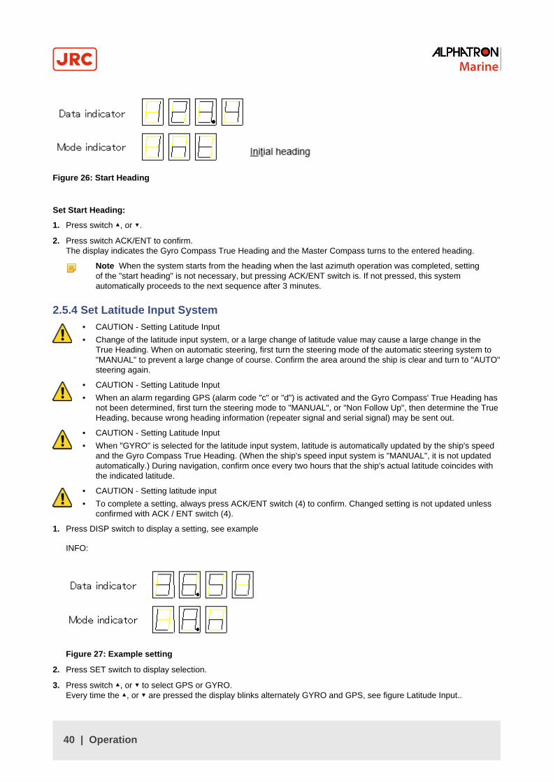
Figure 26: Start Heading
Set Start Heading:
1. Press switch ▲, or ▼.
2. Press switch ACK/ENT to confirm.The display indicates the Gyro Compass True Heading and the Master Compass turns to the entered heading.
Note When the system starts from the heading when the last azimuth operation was completed, settingof the "start heading" is not necessary, but pressing ACK/ENT switch is. If not pressed, this systemautomatically proceeds to the next sequence after 3 minutes.
2.5.4 Set Latitude Input System• CAUTION - Setting Latitude Input
• Change of the latitude input system, or a large change of latitude value may cause a large change in theTrue Heading. When on automatic steering, first turn the steering mode of the automatic steering system to"MANUAL" to prevent a large change of course. Confirm the area around the ship is clear and turn to "AUTO"steering again.
• CAUTION - Setting Latitude Input
• When an alarm regarding GPS (alarm code "c" or "d") is activated and the Gyro Compass' True Heading hasnot been determined, first turn the steering mode to "MANUAL", or "Non Follow Up", then determine the TrueHeading, because wrong heading information (repeater signal and serial signal) may be sent out.
• CAUTION - Setting Latitude Input
• When "GYRO" is selected for the latitude input system, latitude is automatically updated by the ship's speedand the Gyro Compass True Heading. (When the ship's speed input system is "MANUAL", it is not updatedautomatically.) During navigation, confirm once every two hours that the ship's actual latitude coincides withthe indicated latitude.
• CAUTION - Setting latitude input
• To complete a setting, always press ACK/ENT switch (4) to confirm. Changed setting is not updated unlessconfirmed with ACK / ENT switch (4).
1. Press DISP switch to display a setting, see example
INFO:
Figure 27: Example setting
2. Press SET switch to display selection.
3. Press switch ▲, or ▼ to select GPS or GYRO.Every time the ▲, or ▼ are pressed the display blinks alternately GYRO and GPS, see figure Latitude Input..
40 | Operation

Figure 28: Set Latitude Input
4. Press ACK/ENT switch to confirm.
5. Press switch ▲, or ▼, when GYRO is selected, to select the latitude.
6. Press ACK/ENT switch to confirm.The calculated latitude by ship's speed and True Heading is indicated.
2.5.5 Synchronization of the Repeater CompassSynchronization of the Repeater Compass¹.
Note ¹When the repeater is a serial signal type, this operation is not required, because it will synchronizeautomatically. However, ensure that the displayed value coincides with the True Heading selected by this systemafter the repeater switch is turned "ON".
After the last azimuth operation has been completed, the repeater signal and the serial signal are sent.
Figure 29: Repeater Compass
Prior to synchronization of the Master Compass carry out the Repeater Stepper Output Check (Test Mode B).
To stop the master compass. See Turning the Gyro Compass OFF on page 52. The phantom ring starts rotating 360˚.The Sensitive Element rotor should have stopped spinning completely (approx. 4 minutes), for preparation of the varioustests and adjustments.
1. Press the DISP + SET buttons on the operating panel simultaneously.
2. Press the POWER switch (Test Mode B).
3. Set 0˚, 90˚, 180˚ and 270˚ by pressing the ▼ ▲ buttons and press ACK/ENT.
Note Step signals reception instrument (repeater compass) should follow up within 0.5˚.
4. Turn "OFF" each repeater switch.
5. Adjust it to the Gyro Compass True Heading.
6. Turn "ON" the Repeater Switch.
41 | Operation

2.5.6 Settling TimeThe time to "SETTLE" takes approx. 3 hours maximum depending on the starting condition.
2.5.7 Set Ship Speed Input System• CAUTION - Setting Speed Input
• Change of the ship's input system or large change of ship's speed may cause large change of the TrueHeading. When on automatic steering, first turn the steering mode of the automatic steering system to"MANUAL" to prevent a large course change. Confirm the area around the ship is clear and turn to "AUTO"steering again.
• CAUTION - Setting Speed Input
• When an alarm regarding GPS (alarm code "c" or "d") is activated and the Gyro Compass' True Heading hasnot been determined, first turn the steering mode to "MANUAL", or "Non Follow Up", then determine the TrueHeading, because wrong heading information (repeater signal and serial signal) may be sent out.
• CAUTION - Setting Speed Input
• When an alarm regarding LOG (serial) (alarm code "P" or "U") is activated and the Gyro Compass' TrueHeading has not been determined, first turn the steering mode to "MANUAL" or "Non Follow Up", thendetermine the True Heading, because wrong heading information (repeater signal and serial signal) may besent out.
• CAUTION - Setting Speed Input
• When an alarm regarding LOG contact (alarm code "u") is activated and the Gyro Compass' True Headinghas not been determined, first turn the steering mode to "MANUAL" or "Non Follow Up", then determine theTrue Heading, because wrong heading information (repeater signal and serial signal) may be sent out.
• CAUTION - Setting Speed Input
• The setting of the ship's speed input system (and its values for "MANUAL") is automatically saved. When re-starting, the previous ship's speed system setting is activated. When "MANUAL" is selected, stop after ship'sspeed setting is set to zero knots. Also, when turning off and on again with "GPS" selected, confirm that GPSis operating properly.
• CAUTION - Setting latitude input
• To complete a setting, always press ACK/ENT switch to confirm. Changed setting is not updated unlessconfirmed with ACK / ENT switch.
1. Press DISP Switch to display a Ship Speed Setting, see example.
INFO: The example shows when GPS has been selected for the ship's input system.
Figure 30: Ship Speed Indicator
2. Press SET switch to display selection.
3. Press switch ▲, or ▼ to select "MANUAL", "GPS", "LOG" or "LOG (serial signal)".The display blinks successively, see figures.
42 | Operation
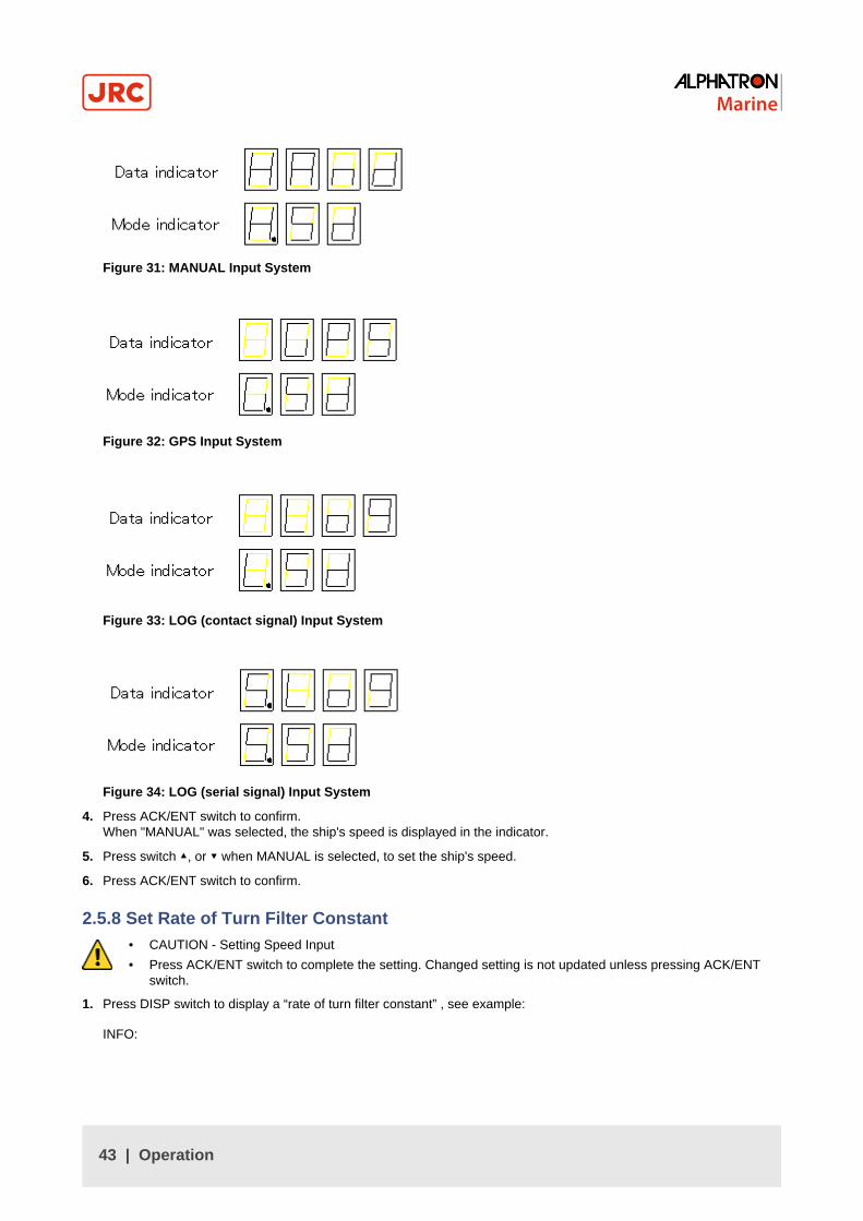
Figure 31: MANUAL Input System
Figure 32: GPS Input System
Figure 33: LOG (contact signal) Input System
Figure 34: LOG (serial signal) Input System
4. Press ACK/ENT switch to confirm.When "MANUAL" was selected, the ship's speed is displayed in the indicator.
5. Press switch ▲, or ▼ when MANUAL is selected, to set the ship's speed.
6. Press ACK/ENT switch to confirm.
2.5.8 Set Rate of Turn Filter Constant• CAUTION - Setting Speed Input
• Press ACK/ENT switch to complete the setting. Changed setting is not updated unless pressing ACK/ENTswitch.
1. Press DISP switch to display a “rate of turn filter constant” , see example:
INFO:
43 | Operation
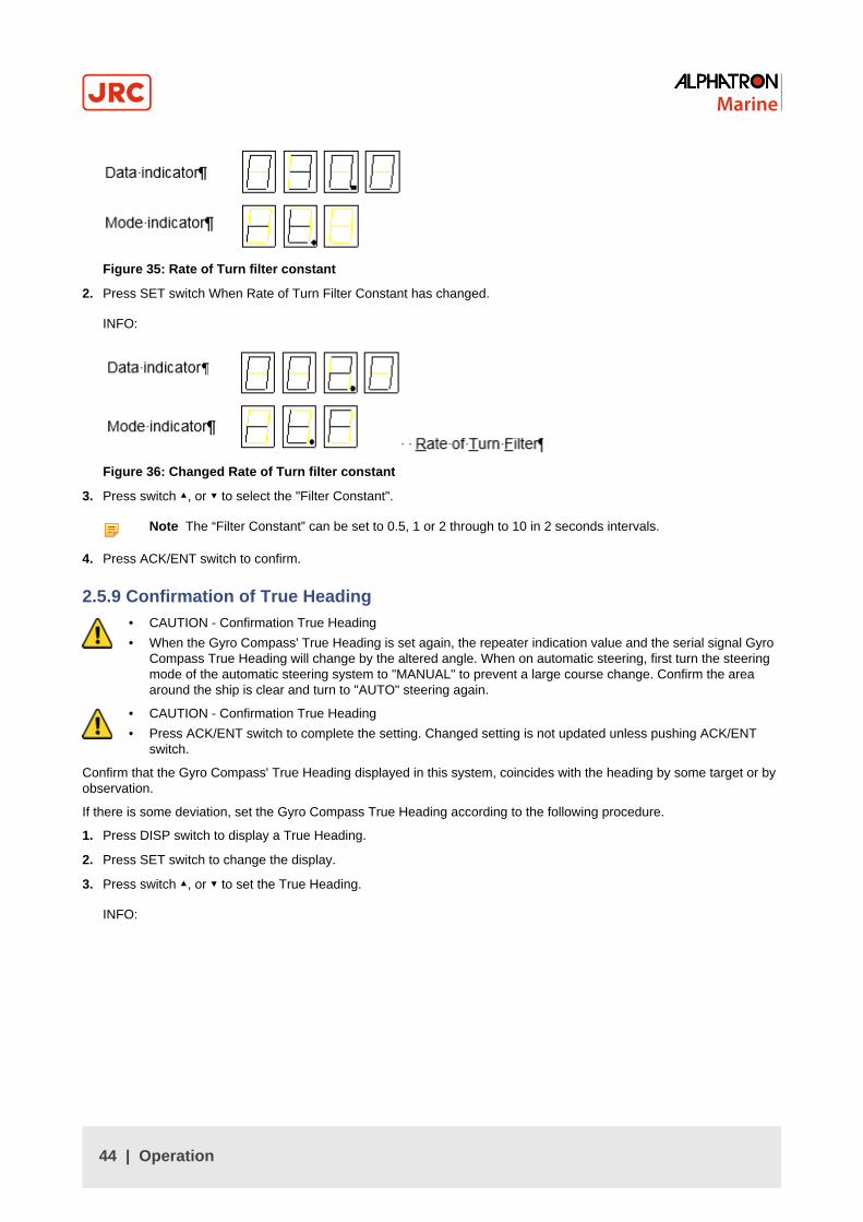
Figure 35: Rate of Turn filter constant
2. Press SET switch When Rate of Turn Filter Constant has changed.
INFO:
Figure 36: Changed Rate of Turn filter constant
3. Press switch ▲, or ▼ to select the "Filter Constant".
Note The “Filter Constant” can be set to 0.5, 1 or 2 through to 10 in 2 seconds intervals.
4. Press ACK/ENT switch to confirm.
2.5.9 Confirmation of True Heading• CAUTION - Confirmation True Heading
• When the Gyro Compass' True Heading is set again, the repeater indication value and the serial signal GyroCompass True Heading will change by the altered angle. When on automatic steering, first turn the steeringmode of the automatic steering system to "MANUAL" to prevent a large course change. Confirm the areaaround the ship is clear and turn to "AUTO" steering again.
• CAUTION - Confirmation True Heading
• Press ACK/ENT switch to complete the setting. Changed setting is not updated unless pushing ACK/ENTswitch.
Confirm that the Gyro Compass' True Heading displayed in this system, coincides with the heading by some target or byobservation.
If there is some deviation, set the Gyro Compass True Heading according to the following procedure.
1. Press DISP switch to display a True Heading.
2. Press SET switch to change the display.
3. Press switch ▲, or ▼ to set the True Heading.
INFO:
44 | Operation

Figure 37: Confirmation True Heading
Note The offset displayed is cleared when the system is turned off, or when the master compass has passedthrough the reference angle of the master compass heading.
4. Press ACK/ENT switch to confirm.
2.5.10 True Heading IndicationWhen all settings have been completed, press DISP switch to display the True Heading in the indicators. If there isanother display in the indicator, the True Heading will be displayed within 30 seconds, if no switch is pressed.
2.6 System Selection• CAUTION - System Selection
• System selection (switching) may cause a large change of True Heading. When on automatic steering, firstturn the steering mode of the automatic steering system to "MANUAL" to prevent a large course change.Confirm the area around the ship is clear and turn to "AUTO" steering again.
Normally use the system selected by the Gyro Compass.
1. Turn "OFF" the repeater switch.
Note When the repeater is a serial signal type, this operation is not required, because it will synchronizeautomatically. However, confirm that the value displayed coincides with "the True Heading" selected by thissystem, after the repeater switch is turned "ON".
2. Press System Selection Switch GYRO together with ACK/ENT switch to select GYRO System.
• In the gyro compass system, press System Selection Switch GYRO together with ACK/ENT switch on theoperating panel to select the Gyro Compass system.
• Press the system selection switch EXT switch together with the ACK / ENT switch to select the "External headingsensor" system, .
Note When a change of system has been selected, it buzzes shortly three times.
3. Synchronize the repeater indication connected to this system with the selected system's heading.
4. Turn "ON" the repeater switch.
Note For steps 3 and 4 applies that, when the repeater is a serial signal type, this operation is not required,because it will synchronize automatically However, confirm that the indicated value coincides with "the TrueHeading" selected by this system after the repeater switch is turned "ON".
2.7 Monitoring while Running• CAUTION - Monitoring in Progress
• Change of the ship's Speed Input System and the Latitude Input System, or large change of the ship's speedand latitude, may cause a large change of the Gyro Compass True Heading. When on automatic steering,first turn the steering mode of the automatic steering system to "MANUAL" to prevent a large course change.Confirm the area around the ship is clear and turn to "AUTO" steering again.
45 | Operation

Perform monitoring while running as follows:
2.7.1 Confirmation of Alarm Status
1. Confirm that the alarm indicator lamp on the operation panel is off.
Note When a failure is activated in the system, the alarm indicator blinks and buzzes.
2. Confirm the alarm code displayed in the indicator.
3. Press ACK/ENT switch to stop buzzer.
Note If the alarm indicator lamp is still on after pressing the ACK/ENT switch, the failure continues.
Note If the failure is only momentarily, the alarm indicator lamp extinguishes at the same time the ACK/ENTswitch is pressed.
4. Take appropriate action according to Alarm on page 47 conditions.
2.7.2 Confirmation of Gyro Compass True Heading
1. Confirm that the Gyro Compass True Heading indicated in this system coincides with the heading by some target orby observation.
2. Make corrections according to Confirmation of True Heading on page 44.
2.7.3 Confirmation of Latitude• CAUTION - Confirmation of Latitude
• Change of the latitude input system or large change of the latitude may cause a large change of TrueHeading. When on automatic steering, first turn the steering mode of the automatic steering system to"MANUAL" to prevent a large course change. Confirm the area around the ship is clear and turn to "AUTO"steering again.
• Confirm that the latitude value displayed on GPS coincides with the latitude value displayed on the indicator.
Note When "GPS" is selected as the latitude input system, the latitude obtained by GPS is displayed.
Note When "GYRO" is selected as the latitude input system and other than "MANUAL" is selected as theship's speed input system, the latitude is automatically updated.
• Confirm the displayed value every time when berthing (or at anchor) and in two hour intervals when GYRO has beenselected.
Note If there is a difference with the ship's actual latitude, set it again according to Set Latitude Input Systemon page 40.
2.7.4 Confirmation of Ship Speed• CAUTION - Confirmation of Ship Speed
• Change of the ship's speed input system or large change of the ship's speed may cause a large change ofTrue Heading. When on automatic steering, first turn the steering mode of the automatic steering system to"MANUAL" to prevent a large course change. Confirm the area around the ship is clear and turn to "AUTO"steering again.
The Gyro Compass generates an error due to the ship's speed. The system calculates this error and corrected TrueHeading is sent out as repeater signal and serial signal.
1. Confirm that the ship's speed displayed coincides with the ship's actual speed at 2 hour intervals.
2. Set it again according to Set Ship Speed Input System on page 42, if there is a difference with the actual speed.
46 | Operation

2.8 Operation Procedure of Master Compass Power Switch (Option)• CAUTION - System Selection
• System selection (switching) may cause large change of True Heading. When on automatic steering, first turnthe steering mode of the automatic steering system to "MANUAL" to prevent a large course change. Confirmthe area around the ship is clear and turn to "AUTO" steering again.
• CAUTION - Operating Procedure Master Compass Switch (Option)
• DO NOT touch the Master Compass Power Switch while the Gyro Compass operates normally, to preventserious damage to the sensitive element, reduce the life cycle of the product, or unexpected problems. TheMaster Compass Power Switch must be operated only when the master compass is in abnormal condition.
With the optional Master Compass Power Switch the running of the compass can be stopped and the output of headinginformation to the external heading sensor can be changed, if connected. This minimizes the loss of heading signal whenany abnormal condition or failure occurs in the master compass. The Master Compass Power-off Switch is located insidethe optional Power Supply Unit.
When any abnormal condition or failure occurs in the master compass, operate the Gyro Compass as follows:
2.8.1 Operation Procedure
1. Change the heading output to external heading sensor system (GPS compass or magnetic compass). see SystemSelection on page 45.
2. Turn the master compass power switch, optionally provided in the steering stand or the control unit, to OFF.
• CAUTION
• DO NOT turn the main power-on switch on the operation panel to OFF.
Note Although the alarm code「3」or「A」will appear and be kept indicating, the output with the externalheading sensor selected will be transmitted and kept on.
2.8.2 Return Procedure
1. First turn the steering mode of the steering control system to HAND.
2. Turn the Compass Power Switch of the operation panel to OFF.
3. Turn the Master Compass Power Switch, located either in the steering stand or in the control unit of the GyroCompass, to ON.
4. Turn the Power Switch in the operation panel of the Gyro Compass to ON.
5. Synchronize the repeater heading with the heading information provided from the external heading sensor asselected in (1) changeover procedure.
Note changeover to the Gyro Compass heading should be done in about three hours after re-starting theGyro Compass.
6. Synchronize the heading of each repeater with the heading of the Gyro Compass, once the heading information ischanged on the Gyro Compass
2.9 Alarm• CAUTION - Alarms
• When the following alarms are activated, the heading information from this system may not be sent at all,or may have a large error. All units operated by the heading information from this system (in particular, theautomatic steering system, etc.) should be operated immediately according to the individual emergencyoperating procedure.
When an alarm is activated, the buzzer will provide an audible alarm and an alarm code will be displayed in the indicator.
1. Confirm alarm code and press ACK/ENT switch to stop buzzer, when an alarm has been generated.
47 | Operation
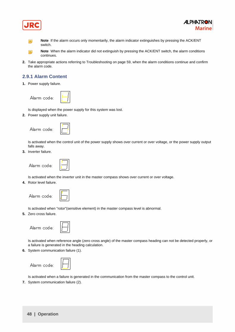
Note If the alarm occurs only momentarily, the alarm indicator extinguishes by pressing the ACK/ENTswitch.
Note When the alarm indicator did not extinguish by pressing the ACK/ENT switch, the alarm conditionscontinues.
2. Take appropriate actions referring to Troubleshooting on page 59, when the alarm conditions continue and confirmthe alarm code.
2.9.1 Alarm Content1. Power supply failure.
Is displayed when the power supply for this system was lost.
2. Power supply unit failure.
Is activated when the control unit of the power supply shows over current or over voltage, or the power supply outputfalls away.
3. Inverter failure.
Is activated when the inverter unit in the master compass shows over current or over voltage.
4. Rotor level failure.
Is activated when "rotor”(sensitive element) in the master compass level is abnormal.
5. Zero cross failure.
Is activated when reference angle (zero cross angle) of the master compass heading can not be detected properly, ora failure is generated in the heading calculation.
6. System communication failure (1).
Is activated when a failure is generated in the communication from the master compass to the control unit.
7. System communication failure (2).
48 | Operation
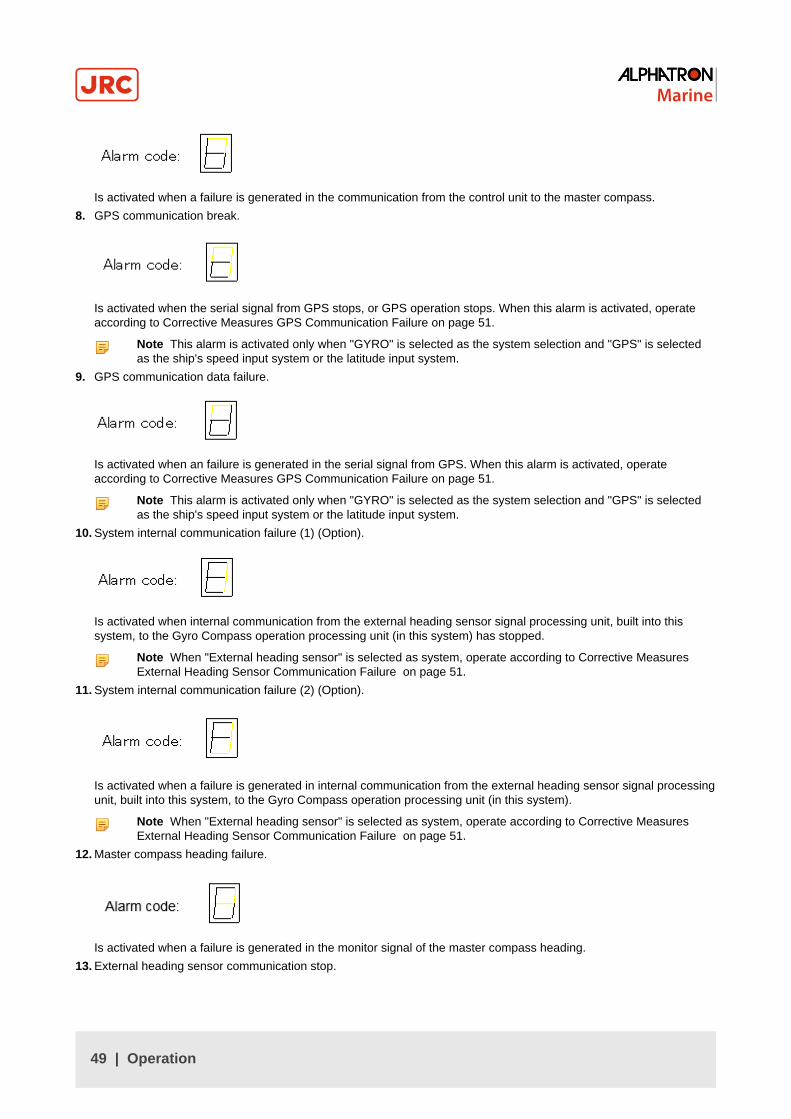
Is activated when a failure is generated in the communication from the control unit to the master compass.
8. GPS communication break.
Is activated when the serial signal from GPS stops, or GPS operation stops. When this alarm is activated, operateaccording to Corrective Measures GPS Communication Failure on page 51.
Note This alarm is activated only when "GYRO" is selected as the system selection and "GPS" is selectedas the ship's speed input system or the latitude input system.
9. GPS communication data failure.
Is activated when an failure is generated in the serial signal from GPS. When this alarm is activated, operateaccording to Corrective Measures GPS Communication Failure on page 51.
Note This alarm is activated only when "GYRO" is selected as the system selection and "GPS" is selectedas the ship's speed input system or the latitude input system.
10. System internal communication failure (1) (Option).
Is activated when internal communication from the external heading sensor signal processing unit, built into thissystem, to the Gyro Compass operation processing unit (in this system) has stopped.
Note When "External heading sensor" is selected as system, operate according to Corrective MeasuresExternal Heading Sensor Communication Failure on page 51.
11. System internal communication failure (2) (Option).
Is activated when a failure is generated in internal communication from the external heading sensor signal processingunit, built into this system, to the Gyro Compass operation processing unit (in this system).
Note When "External heading sensor" is selected as system, operate according to Corrective MeasuresExternal Heading Sensor Communication Failure on page 51.
12. Master compass heading failure.
Is activated when a failure is generated in the monitor signal of the master compass heading.
13. External heading sensor communication stop.
49 | Operation

Is activated when the serial signal from the external heading sensor has stopped or the external heading sensor hasstopped operating.
14. External heading sensor data failure.
Is activated when a failure is generated in the serial signal from the external heading sensor.
Note When this alarm is activated, operate according to Corrective Measures External Heading SensorCommunication Failure on page 51.
15. LOG (serial signal) communication stop.
Is activated when the serial signal from LOG (serial signal) has stopped, or LOG (serial signal) has stoppedoperating.
Note This alarm is activated only when "GYRO" is selected in the system selection and "LOG (serial signal)"is selected as the ship's speed input system.
16. LOG (serial signal) data failure.
Is activated when a failure is activated in the serial signal from LOG.
Note When this alarm is activated, operate according to Corrective Measures LOG (serial signal)Communication Failure on page 51.
Note This alarm is activated only when "GYRO" is selected in the system and "LOG (serial signal)" isselected as the ship's speed input system.
17. LOG (contact) failure.
Is activated when a failure is activated in LOG (contact).
Note This alarm is activated only when "LOG" is selected for the ship's speed input system.
18. E5V failure
Is activated when failure is generated in the power supply for the serial signal.
50 | Operation

2.9.2 Corrective Measures GPS Communication Failure• CAUTION - Corrective Measures GPS Communication Failure
• When an alarm related to GPS (alarm code "c" or "d") is activated and the Gyro Compass' True Heading hasnot been determined, first turn the steering mode to "MANUAL", or "Non Follow Up", then determine the TrueHeading, because wrong heading information (repeater signal and serial signal) may be sent out.
• CAUTION - Corrective Measures GPS Communication Failure
• Determination of the True Heading may cause large change of sent heading information. During automaticnavigation, great care should be taken, because large course changes may have happened.
The True Heading, which currently is displayed and sent is the corrected value based on the corrected value immediatelybefore the GPS alarm was activated.
1. Select other mode than GPS, when GPS has been selected as the ship's speed input system.
Note Refer to Set Ship Speed Input System on page 42.
2. Select other mode than GPS, when GPS has been selected as the latitude input system.The True Heading indication is blinking showing the True Heading calculated, based on the changed ship's speedand latitude
3. Press ACK/ENT switch to confirm True Heading.The True Heading indication lights up and the True Heading sent is also confirmed.
2.9.3 Corrective Measures External Heading Sensor Communication Failure• CAUTION - Corrective Measures EXTERNAL HEADING SENSOR Communication Failure
• When an alarm regarding the EXTERNAL HEADING SENSOR (alarm code "E", "F", "L" and "N") is activated,the heading information (repeater signal and serial signal) immediately before the alarm generated is sent.First turn the steering mode to "MANUAL" or "Non Follow Up", and then determine the True Heading. OnceTrue Heading has been determined, the system's heading is sent out.
• CAUTION - Corrective Measures EXTERNAL HEADING SENSOR Communication Failure
• Determination of the True Heading may cause large change of sent heading information. During automaticnavigation, great care should be taken, because large course changes may have happened.
When the alarm related to the External Heading Sensor is activated, the True Heading of the data indicator is blinking.
The True Heading that is currently displayed on the indicator was the True Heading before an alarm was activated.When the alarm has been recovered the received heading will be indicated.
When the alarm continues, the True Heading cannot be determined.
The True Heading sent out, is the heading immediately before the alarm was activated.
1. Confirm that the alarm related to the external heading sensor has been recovered.
2. Press the ACK/ENT switch as the True Heading is displayed in the indicator.The External Heading Sensor True Heading indicator for the True Heading lights up and the sent out True Heading isthe confirmed true heading.
2.9.4 Corrective Measures LOG (serial signal) Communication Failure• CAUTION - Setting Speed Input
• When an alarm regarding LOG (serial) (alarm code "P" or "U") is activated and the Gyro Compass' TrueHeading has not been determined, first turn the steering mode to "MANUAL" or "Non Follow Up", thendetermine the True Heading, because wrong heading information (repeater signal and serial signal) may besent out.
• CAUTION - Corrective Measures LOG Communication Failure
• Determination of the True Heading may cause large change of sent heading information. During automaticnavigation, great care should be taken, because large course changes may have happened.
When a failure related to LOG (serial signal) is activated, the data indicator is blinking.
51 | Operation

The Gyro Compass True Heading and the heading information sent out, which are currently displayed, is the correctedvalue based on the ship's speed immediately before the alarm was activated.
1. Select other mode than "LOG (serial signal)" for the ship's speed input system. See Set Ship Speed Input System onpage 42
2. Press ACK/ENT switch to confirm True Heading, when the Gyro Compass true heading, calculated from thecorrected ship's speed, display is blinking in the indicator.The True Heading indicator lights up and the True Heading sent out is also confirmed.
2.9.5 Corrective Measures LOG (contact) Failure• CAUTION - Corrective Measures LOG Contact Communication Failure
• When an alarm regarding LOG Contact (alarm code "u") is activated and the Gyro Compass' True Headinghas not been determined, first turn the steering mode to "MANUAL" or "Non Follow Up", then determine theTrue Heading because wrong heading information (repeater signal and serial signal) may be sent out.
When a failure related to LOG (contact) is activated, the data indicator is blinking.
The Gyro Compass True Heading and the heading information sent out, which are currently indicated, is the correctedvalue based on the ship's speed immediately before the alarm was activated.
1. Select other mode than "LOG" for the ship's speed input system.
Note Refer to Set Ship Speed Input System on page 42.
2. Press ACK/ENT switch to confirm True Heading, when the Gyro Compass true heading, calculated from thecorrected ship's speed, display is blinking in the indicator.The True Heading indicator lights up and the True Heading sent out is also confirmed.
2.10 Turning the Gyro Compass OFF
1. Press the POWER button on the Control Panel.The light in the Power Button will extinguish.
2. Press the POWER button again to activate the rotor brake function.The light in the Power Button will light up again.
Rotor brake active is indicated by:
• Flashing display.
• The Gyro Compass makes a soft clicking sound.
Note The rotor brake function will be active for a maximum of 4 minutes.
Note The sensitive element may be damaged, if the rotor brake is not activated.
52 | Operation

3 SpecificationsRefer to the As Built plan kept aboard and table below.
Model Description AlphaMidiCourse
Display Digital with 7 digits
Performance Settle point error < 0.3°
Settle point repeatability < 0.2°
Static accuracy < 0.3°
Dynamic accuracy < 0,5°
Follow-up speed max. 75°/second
Settling time < 4 hours
Outputs Stepper 1x Stepper DC24V, 6 steps/°
Serial data 4x output RS-422/ RS-485
IEC61162-1/2
Status/alarm Dry contacts (alarm ack, buzzer stop)
Inputs Latitude NMEA 0183 via RS-422 from GPS
Speed 200 or 400 pulses/nm from log NMEA 0183 via RS-422
Compensation Latitude 70°N to 70°S
Speed 0-50 knots
Environmental Ambient operatingtemperature
–10°C – +50°C
Gimbal limits ± 45° roll and pitch
Mean time between failures(MTBF)
35000
Operating Voltage Input voltage 24VDC
Power Start-up 140 VA AC 70 VA AC (Operating)
Dimensions Size 340mm (h) x 340mm (w) x 438mm (d)
Weight 23 kg. (Master Compass)
7 kg. (Control unit)
Accessories Included Control Unit
Standards IMO A424(XI), ISO8728, Marine Equipment Directive96/98/EC
Table 10: Specifications
No. Name Type Qty Mass(kg)
Finish Remarks Dwg.No.
1 BASIC SPECIFICATIONS - - - - -
53 | Specifications

No. Name Type Qty Mass(kg)
Finish Remarks Dwg.No.
Alpha-MidiCourse
- - - GENERAL
INPUT SIGNAL
INPUT SIGNALSENTENCE
OUTPUTSIGNAL
1 GYRO COMPASS
OUTPUTSIGNALSENTENCE
2 INSTALLATION NOTES Alpha-MidiCourse
- - -
3 ENTER UNITWIRING DIAGRAMS
Alpha-MidiCourse
- - -
EXTERNAL FORM - - - -
1 MASTER COMPASS Alpha-MidiCourse
1 23 RAL -7012Basaltgrey
2 CONTROL UNIT Alpha-MidiCourse
1 7 Wall mount type
4
3 SPARE PARTS & TOOLBOX
1 CLEAR
SPARE PARTS & TOOLS LIST - - - -5
1 GYRO COMPASS 1 - -
Table 11: Contents and Components List
Sensor Type of Signal *¹Protocol
Sentence
GPS IEC61162-1 / IEC61162-1 Ed.2 A Refer to Input SignalSentence
SPEED LOG *² IEC61162-1 / IEC61162-1 Ed.2 A Refer to Input SignalSentence
200 or 400 Pulses/n mileSPEED LOG *² DRY CONTACT -
5V / 5mA
Table 12: Input Signal Specifications
*¹: Refer to Type of Protocol.
*²: Input either or both signal.
54 | Specifications

A
BAUD RATE 4800 bps
DATA BITS 8 bits
PARITY none
STOP BITS 1
TRANSMIT FREQ. 1 s
Table 13: Type of Protocol
GPS DATA NO.1
$-GGA,x,xx,x,N,xx.x,E,x,∼*hh<CR><LF>
↑LAT.: ↑GPSQI:GPS
$-GLL,xxxx.xx,N,xxxx.xx,E∼*hh<CR><LF>
↑LAT.:
Note GGA sentence is high priority.
DATA NO.2
$-VTG,xx,T,xx,M,xx.x,N,xx,K*hh<CR><LF>
↑SPEED (knots)
SPEED LOG DATA NO.1
$-VBW.x.x.x.x.A.x.x.x.x.A∼*hh<CR><LF>
↑SPEED (knots) STATUS
↑GROUND SPEED (knots)
↑WATER SPEED (knots)
Note Ground speed is high priority
Table 14: Input Signal Sentence
Circuit Type of Signal *¹ Protocol Sentence
SELECTED COMPASS DC24V STEP 1/6˚ - -
SELECTED COMPASS *² IEC61162-1 Ed. / IEC61162-2 A / B Refer to output signalsentence.
Table 15: Output Signal Specifications
55 | Specifications

*¹: Refer to type of Protocol.
*²: Type of Protocol can be selected for each circuit. (Refer to wiring diagram regarding number of circuits).
A B
BAUD RATE 4800 bps 38400 bps
DATA BITS 8 bits 8 bits
PARITY none none
STOP BITS 1 1
TRANSMIT FREQ. 1sec/200msec/100msec 20 ms
Table 16: Type of Protocol
56 | Specifications

4 Maintenance• WARNING - Maintenance
• During maintenance or check of the product, touching internal parts may cause electric shock, becausethe ship's power supply is still connected to the system distribution board, even if the main power switch ofthis product is turned "OFF". Do not touch internal parts such as terminal boards, power supply unit, etc. Ifnecessary, disconnect the power cable from the ship’s distribution board. A warning label is attached to pointout this danger.
Figure 38: Warning Label
• CAUTION - Maintenance and check
• Main units of this system consist of electronic circuits of high reliability. If a failure occurs, perform the checkand maintenance as described in this chapter and correct the fault(s) to prevent further risk of failure and tomaintain the system's performance. Failure to carry this out, the detection of the failure sign will be delayedand may cause accidents such as collision or grounding.
• CAUTION - Prohibition
• Do not use insulation tester or other device to test system insulation as it will damage internal electricalcomponents. Always disconnect the wiring connected to this system before testing related power distributionlines with such testers.
4.1 General ProceduresThis system consists of carefully selected parts based on safety design. Periodical checks (operational checks) andmaintenance must still be performed for long term satisfactory operation.
Main purpose of the periodical checks and maintenance is to catch signs of equipment failure at an early stage. Repairson call in port as a result of these checks will prevent unexpected failures to a minimum while sailing.
For the periodical checks and maintenance of the equipment connected to this system, like the automatic steeringsystem, magnetic compass system, etc., refer to the separate individual Operator's Manuals.
Record content of the checks and maintenance performed in the log book.
1. Assign a person in charge of periodical checks and maintenance for this system to be executed under hisresponsibility.
2. Check and re-tighten loosened screws of mechanical connections, due to body shock and resonance vibration.
3. Re fix parts, fixing screws, mounting parts, reinsert connectors and repair loosened cables and wires.
Note Most parts used in the main sections of this system are electronic (electric) parts. Occurrence ofelectronic parts trouble themselves is very seldom, and troubles in mounting sections of electronic (electric)parts, being about to disconnect wires at roots or lead wires of electric parts, occur easily due to hull bodyshock or resonance vibration. These are the points to be checked.
4. Record strange motions, smells, sounds and heat generation, etc. different from those that exist in normal operations.
5. Request repair from Alphatron Marine Service Engineer, or agent.
6. Have the system checked periodically by Alphatron Service Engineer, or agent.
7. Have the checklist table and the log book evaluated by the engineer.
57 | Maintenance

Note The trouble shooting and repair should be carried out by the engineer according to the results of thechecks of the faulty items.
4.2 Periodical ChecksUse the periodical check table for the periodical check. See Periodic Check Table 1 on page 78
Frequency of the checks are:
1. Items to be executed once a day.
2. Once a half year / once a year.
Checked items are regarded as normal, or not, by comparing their condition as at installation time on the ship as astandard.
1. Copy and use periodical check table (including operational check) [once a day], in the Appendix. See Figure 51:Periodic Check Table 1 on page 78
Note When table is full file it.
2. Copy and use periodical check table (including operational check) [once a half year / once a year], in the Appendix.See Figure 52: Periodic Check Table 2 on page 79
Note When table is full file it.
4.3 Warning Label CheckAlways check and clean warning labels so they are easy to read.
When warning labels become dirty or detached, request new ones from Alphatron Marine.
4.4 Spare Parts
Part Name Part No.
Weight 9.0 G 10210101-
Weight 3.0 G 10210102-
Weight 3.8 G 10210103-
Weight 2.3 G 10210104-
Weight 1.2 G 10210105-
Weight 0.95 G 10210106-
Weight 0.6 G 10210107-
Weight 0.3 G 10210108-
Weight 0.17 G 10210109-
Weight 6.6 G 10210110-
Guide Screw [A] 11002595-
Guide Screw [A] 11002596-
Sensitive Element 3107.9152
Brush 3107.9154
Step Motor 3107.9158
58 | Maintenance

Part Name Part No.
Belt 3107.9160
HRZC PWB 3107.9162
Inverter PWB 3107.9164
Slip Ring 3107.9166
Flexibel Wire (east) 3107.9168
Gpower PWB 3107.9170
Table 17: Spare Parts List
4.5 Disposal MethodWhen disposing of this system, it should be treated as industrial waste and disposed of in accordance with the laws andregulations.
4.6 TroubleshootingWhen a failure occurs it may be corrected by following the steps contained in list below.
4.6.1 General• CAUTION - Troubleshooting
• When an alarm is activated, immediately confirm content of the activated alarm and take appropriatemeasures. ●When a failure has been activated, confirm area around the ship is clear to perform check andtake appropriate measures in non-hazardous sea area, stopping the ship as a rule.
Two things must be considered when a failure has become apparent in this system, or in the connected externalequipment:
1. An alarm is displayed in this system.
2. A failure exists in part, or in all functions of this system.
4.6.2 Before TroubleshootingBefore starting the troubleshooting procedure consider the following:
1. Firstly ensure the ship's safety. Then identify where the cause of the failure is located; in the system side, or in theexternal equipment side.
• Identify the side of the failure.
• Confirm the alarm content according to Alarm on page 47.
When the following alarms are displayed, the cause maybe in the external equipment, or the connected line.
When the following alarms are displayed, the cause maybe in this system.
E-1 E-n E-2 E-G
E-c E-P E-3 E-r
E-d E-U E-6
E-E E-u E-8
E-F E-A
E-L E-b
59 | Maintenance

2. Tools (instruments) required for checking:
• Minus head screw driver and general tools
• Circuit tester
4.6.3 Corrective MeasuresMeasures can be taken to rectify some failures.
• CAUTION - Corrective Measures
• Before checking and replacing of fuses, and disconnecting / connecting of each unit, connector, printedcircuit, terminal cable, turn "OFF" the power switch of the operating panel, and disconnect the power cablefrom the ship’s distribution board, etc. It may cause electric shock and failure if left in "ON" position.
4.6.4 Corrective Measures when an Alarm is ActivatedWhen an alarm is activated, follow procedures below:
1. Confirm that the alarm indicator light on the Operating Panel blinks and check alarm content displayed in the DataDisplay when the alarm buzzes.
2. Press ACK/ENT switch to stop the buzzer.If the alarm indicator light extinguishes, the system has been restored.
Note Wait a while to observe whether the alarm is repeated, then take appropriate action. Write down thesetting values and the other data related to the alarm, and various status conditions including sea conditions.
Note If the alarm indicator light continues blinking after pressing ACK/ENT switch, shows that the failure stillexists.
3. Confirm alarm occurrence number and alarm content from the data indicator, refer to Alarm on page 47 and checkaccording to Failure Phenomena and Corrective Measures on page 60, regarding the displayed alarm content.
4.6.5 Failure Phenomena and Corrective MeasuresWhen a failure has occurred, take the following actions.
Contact Alphatron Marine, or agency if the failure was not repaired.
• CAUTION - Failure Phenomena Corrective Measures
• Whenever the internal setting of the system is changed, follow instructions of the Alphatron Service Engineer.
• When another failure is activated than appeared in this clause, or a replaced fuse has blown again, turn"OFF" the power switch of the operating panel, disconnect the power cable from the ship’s distribution boardand request repair from an Alphatron Service Engineer.
• When a failure has occurred and it has not been repaired according to this clause, turn "OFF" the powerswitch of the operating panel and request an Alphatron Service Engineer to repair it on making a call to port.Even if it has been repaired, request an Alphatron Service Engineer to check it.
4.6.5.1 Power Supply Failure (alarm code 1)
1. Confirm that the power is connected.
2. Confirm the automatic steering system type according to the As Built plan of the ship.
60 | Maintenance

INFO:
Stand alone type (Model - I) Voltage
The system where both the master compass and the control unit arenot built into the automatic steering system.
Input terminals of the emergency power supply (between 1B+ and1B- of the external terminal board TB3-5 and TB3-6.
24 V DC, within -20 % to +30 %
3. Contact Alphatron Marine service engineer, or agent, immediately after checking steps 1 and 2 above.
4.6.5.2 Power Supply Failure (alarm code 2)
1. Turn OFF the power switch.
2. Wait approx. 20 seconds before turning ON again.
3. Take action according to Start on page 38, if no alarm code 2 was activated.
4. Turn OFF the power switch and request repair from Alphatron Marine service engineer, or agent, if an alarm isactivated again in alarm code 2.
4.6.5.3 Inverter Failure (alarm code 3)
• CAUTION - Not all repeaters operate
• When checking fuses, turn OFF the power switch, and disconnect the power cable from the ship’s distributionterminal board.
1. Turn OFF the power switch.
2. Turn ON again after approx. 20 seconds.
3. Take action according to Start on page 38, if no alarm code 3 was activated.
4. Check the inverter fuse (F1-12A), located in the base of the master compass, Master Compass on page 70, if analarm is activated again in alarm code 3.
5. Turn OFF the power switch and request repair from Alphatron Marine service engineer, or agent.
4.6.5.4 Rotor Level Failure (alarm code 6)
• CAUTION - Rotor Level Failure (alarm code 6)
• Turn OFF the power switch.
1. Turn OFF the power switch.
2. Turn ON again after approx. 20 seconds.
3. Take action according to Start on page 38.
4. Observe the heading of the Gyro Compass for two hours or more.
5. Contact Alphatron Service Engineer, or agent, after checking heading of the Gyro Compass.
4.6.5.5 Zero Cross Failure (alarm code 8)
• CAUTION - Zero Cross Failure (alarm code 8)
• Determination of the Gyro Compass True Heading when alarm code 8 is activated, may cause a largechange of the True Heading. During automatic navigation, take great care, because a large course changemay have happened.
1. Press DISP switch.
Note Ensure SSG or GYT is shown in Mode Display.
61 | Maintenance

Note Data Display will be blinking.
2. Press ACK/ENT switch to determine the Gyro Compass True Heading.
Note Set True Heading again according to Confirmation of True Heading on page 44, if the determined TrueHeading has an error.
3. Contact Alphatron Marine, or agent, even when True Heading has been recovered.
4.6.5.6 System Communication Failure (1) (alarm code A)
1. Turn OFF the power switch.
2. Turn ON again after approx. 20 seconds.
3. Take action according to Start on page 38, if no alarm code A was activated.
4. Turn OFF the power switch of this system, when this alarm is generated again.
5. Disconnect the power cable from the ship’s distribution board.
6. Confirm the connection / contact between the external terminal board of the master compass and the externalterminal board (connector) inside of the control unit.
INFO: One Gyro Compass system.
External terminal board of the master compass: MTTRM, PWB, TB2, MR+ / -
External terminal board of the control unit: GTERM, PWB, TB1, MR+ / -
Table 18: Stand alone type (Model - I)
7. Contact Alphatron Marine Service Engineer, or their agent, after checking steps 2 to 7.
4.6.5.7 System Communication Failure (2) (alarm code b)
1. Turn OFF the power switch.
2. Turn ON again after approx. 20 seconds.
3. Take action according to Start on page 38, if no alarm code b was activated.
4. Turn OFF the power switch of this system, when this alarm is generated again.
5. Disconnect the power cable from the ship’s distribution board.
6. Confirm the connection / contact between the external terminal board of the master compass and the externalterminal board (connector) inside of the control unit.
7. Contact Alphatron Marine Service Engineer, or their agent, after checking steps 2 to 6.
Note Refer to the As Built plan of the ship to confirm type.
4.6.5.8 GPS Communication Stop (alarm code c) or Failure of GPS data (alarm code d)
1. Select other mode other than "AUTO" of the automatic steering system.
2. Confirm that GPS operates properly.
Note Operate GPS according to "GPS Operator Manual", if it does not operate properly.
3. Change the input system according to Corrective Measures GPS Communication Failure on page 51, if it was notrecovered after executing step 2.
4. Contact Alphatron Marine Service Engineer immediately, after checking steps 1 to 3.
62 | Maintenance
4.6.5.9 System Internal Communication Failure (1) (alarm code E) or System Internal CommunicationFailure (2) (alarm code F)
1. Confirm that the external heading sensor signal processing unit of this system operates properly.
2. Contact Alphatron Service Engineer, or agent, after checking step 1.
4.6.5.10 Master Compass Heading Failure (alarm code G)
• CAUTION - Master Compass Heading Failure (alarm code G)
• When an alarm code G is activated, the Gyro Compass True Heading may have an error. New input of theTrue Heading may cause a large change of the True Heading. When on automatic navigation, first turn thesteering mode to "MANUAL", then determine the True Heading to prevent turning course with larger angle.Confirm area around ship is clear and turn to "AUTO" steering again.
1. Confirm that the Gyro Compass True Heading displayed in this system coincides with the heading by some target, orby observation.
2. Make correction according to Confirmation of True Heading on page 44, if there is an error is detected in step 2.
3. Contact Alphatron Marine Service Engineer, or agent, after checking steps 1 and 2.
4.6.5.11 External Heading Sensor Communication Stop (alarm code L) or External Heading SensorData Failure (alarm code n)
1. Confirm that the external heading sensor operates properly.
2. Operate it according to the Operator's Manual for the external heading sensor, if it does not operate properly.
3. Take appropriate actions according to Corrective Measures External Heading Sensor Communication Failure onpage 51, if it was not recovered after executing step 2.
4. Contact Alphatron Marine Service Engineer, or agent, after checking steps 1 to 3.
4.6.5.12 LOG (serial signal) Communication Stop (alarm code P) or LOG (serial signal) Data Failure(alarm code U)
1. Confirm that LOG operates properly.
2. Operate it according to the Operator's Manual of LOG, if it does not operate properly.
3. Change the input system according to Corrective Measures LOG (serial signal) Communication Failure on page 51,if it was not recovered after executing step 2.
4. Contact Alphatron Marine Service Engineer, or agent, after checking steps 1 to 3.
4.6.5.13 LOG Contact Failure (alarm code u)
1. Confirm that LOG operates properly.
2. Operate it according to the Operator's Manual of LOG, if it does not operate properly.
3. Change the input system according to Corrective Measures LOG (contact) Failure on page 52, if it was notrecovered after executing step 2.
4. Contact Alphatron Marine Service Engineer, or agent, after checking steps 1 to 3.
4.6.5.14 E5V Failure (alarm code r)
1. Confirm that all equipment connected to this system operates properly.
63 | Maintenance
Note Refer to the As Built plan kept on board of the ship for the connected equipment.
2. Operate it according to the particular Operator Manual of the equipment, when a failure has been activated.
3. Contact Alphatron Marine Service Engineer, or agent, after checking steps 1 and 2.
4.6.5.15 Gyro Compass does not Function, when Power Switch on the Operating Panel turned ON.
• WARNING - Power Supply Failure (alarm code 1)
• Pay full attention to avoid electric shock when checking the power supply.
• When checking fuses, turn "OFF" the power switch on the operating panel and further disconnect the powercable from the ship’s distribution board before checking fuses.
1. Confirm there is power on the power supply cable and the emergency power supply.
INFO: To confirm this, execute as in Power Supply Failure (alarm code 1) on page 60.
2. Check fuses if there is no problem with the power supply.
Note First disconnect the main/emergency power supply.
INFO: One Gyro Compass system
Fuse F6 (Main Supply) and F9 (Emergency Supply, see Table 19: Fuse Replacement on page 65) are located inthe upper side of the ITERM terminal board of the control unit, see Figure 45: Stand alone type Control Unit of OneGyro Compass System on page 72 and Figure 49: Terminal Board on page 76
3. Contact Alphatron Marine Service Engineer, or agent, immediately after checking steps 1 and 2.
4.6.5.16 Alarm is Activated at the Same Time when Power Switch Turned ON
1. Turn OFF the power switch, when error code "3" and "A" are activated at the same time
2. Turn back ON after approx. 1 minute.
3. Check the fuse of the inverter, if the status does not change after step 1.
Note The fuse (F1 - 12A) is situated in the base of the master compass, see Master Compass on page70.
4.6.5.17 Others
When failures and alarms, other than those mentioned before, are activated and when the replaced fuse has blownagain, take following actions:
1. Turn OFF the power switch on the operating panel.
2. Disconnect the power supply from the ship’s distribution board, etc.
3. Contact Alphatron Marine Service Engineer, or agent, immediately.
Note In such event, prompt service action is available when the alarm code is advised.
4.6.5.18 When Failures cannot be fixed On Board
Refer Information to be supplied to Alphatron Marine on page 80 when failures cannot be fixed on board.
64 | Maintenance

4.6.6 Fuse ReplacementTo replace a fuse when it has blown:
Figure 39: Fuses Control Unit
1. Turn OFF the power switch on the operating panel.
2. Disconnect the power supply from the ship’s distribution board and the emergency power supply of this system.
3. Investigate the cause of the fuse blowing.
Note It will blow again, unless the cause is removed when replaced with the same capacity fuse and itrecovered for a while. Note that there is some characteristic dispersion for the same capacity fuse.
Note Confirm that the voltage at the following external terminal board is zero. To confirm this, perform actionas in Power Supply Failure (alarm code 1) on page 60.
Fuse No. Capacity TB-No. Signal Description
F1 TB1-33 1R24+ Power supply for ch. 1 serial repeater
F2 TB1-38 2R24+ Power supply for ch. 2 serial repeater
F3 TB1-43 3R24+ Power supply for ch. 3 serial repeater
F4 TB1-48 4R24+ Power supply for ch. 4 serial repeater
F5
1A
TB1-21 ST15 Power supply for ch. 1 step motor repeater
F6 10A TB3-1 24M+Main power supply (standard type)
Master compass power supply (with Power supply unit)
F7 3.15A TB3-3 24B+ Power supply for ICIF and IOPT board (with Powersupply unit)
F8 6.3A TB2-1 24R+ Power supply for repeaters (with Power supply unit)
F9 10A TB3-5 24BT+ Emergency power supply (standard type)
Table 19: Fuse Replacement
Note All fuses are ∅5.2x20mm, except Master Compass fuse.
65 | Maintenance

4.6.6.1 Master Compass (Inverter fuse F1)
Fuse F1 is located inside the fuse holder in the front and is ∅6.35x31,8mm . All other fuses are ∅5.2x20mm.
Figure 40: Master Compass Inverter Unit
1. Press and turn the fuse holder edge counterclockwise with a screw driver to open the fuse holder.
2. Turn clockwise to close it, after fuse has been replaced.
66 | Maintenance

5 AppendicesThe Appendix contains Drawings and Periodic Check Tables.
5.1 DrawingsDrawing Contents:
1. Outline Control Unit (One Gyro Compass System).
2. Operating Panel.
3. Master Compass.
4. Stand alone type Control Unit of One Gyro Compass System.
5. Connection Diagram.
6. Installation Drawing.
7. Terminal Board.
8. ITERM pwb.
67 | Appendices

5.1.1 Outline Control Unit (One Gyro Compass System)
Figure 41: Control Box
68 | Appendices

5.1.2 Operating Panel
Figure 42: Operating Panel
69 | Appendices

5.1.3 Master Compass
Figure 43: Main Unit
70 | Appendices
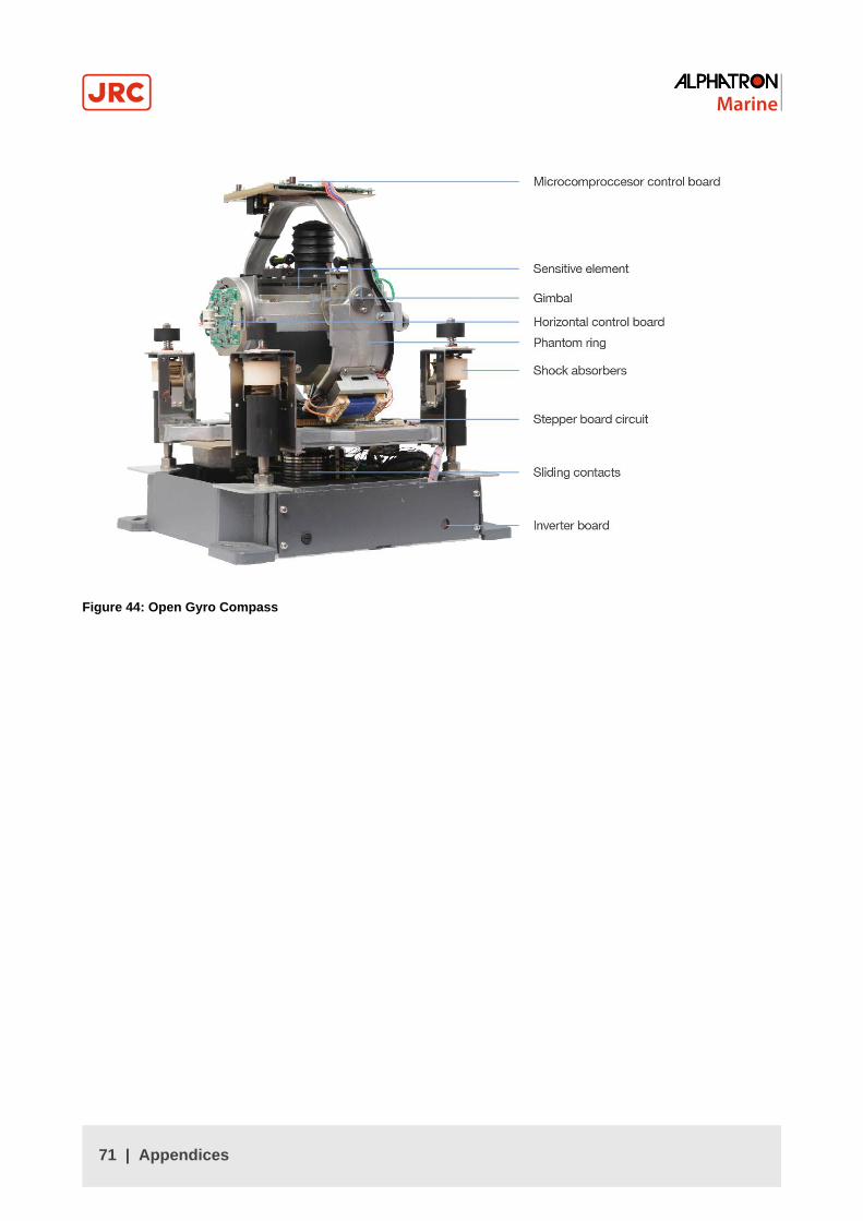
Figure 44: Open Gyro Compass
71 | Appendices

5.1.4 Stand Alone Type Control Unit of One Gyro Compass System
Figure 45: Stand alone type Control Unit of One Gyro Compass System
72 | Appendices
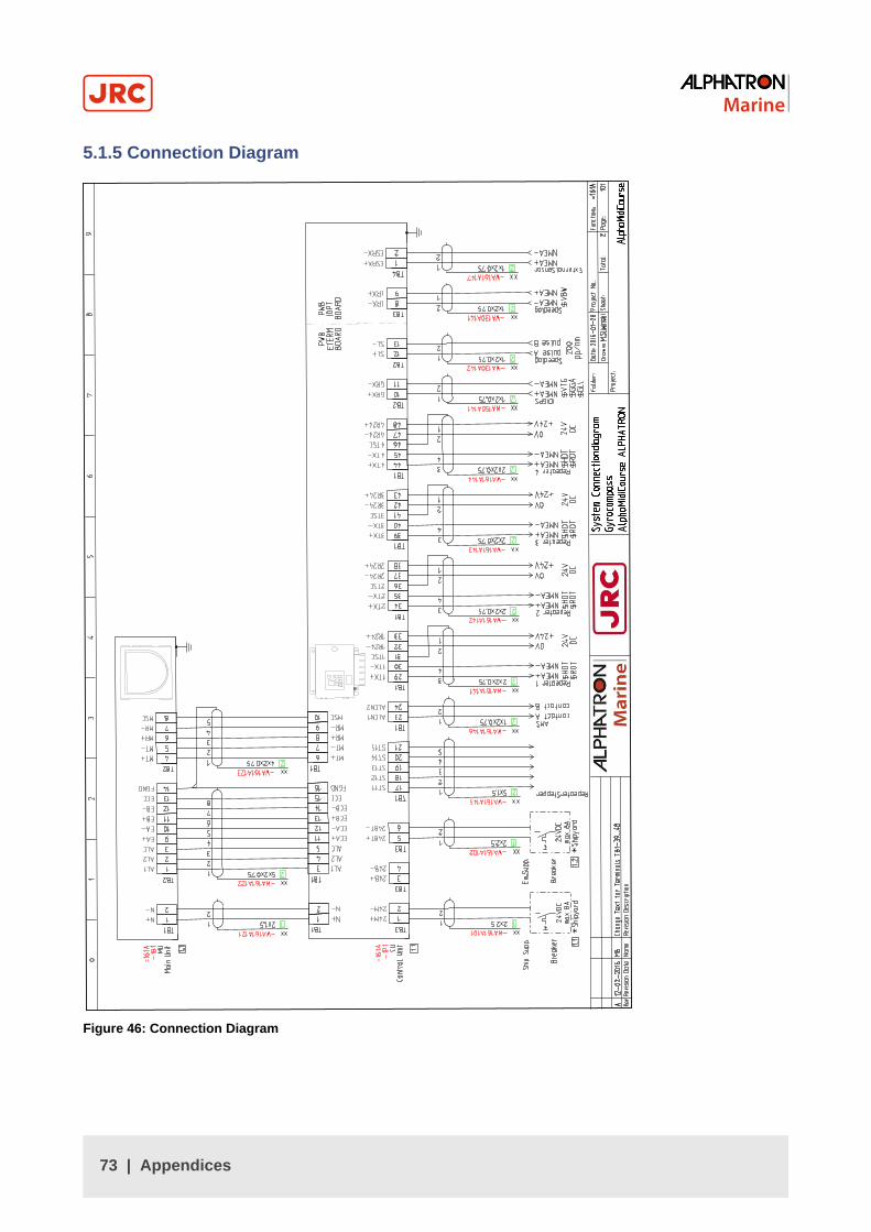
5.1.5 Connection Diagram
Figure 46: Connection Diagram
73 | Appendices

5.1.6 Cable Diagram
Figure 47: Cable Diagram
74 | Appendices
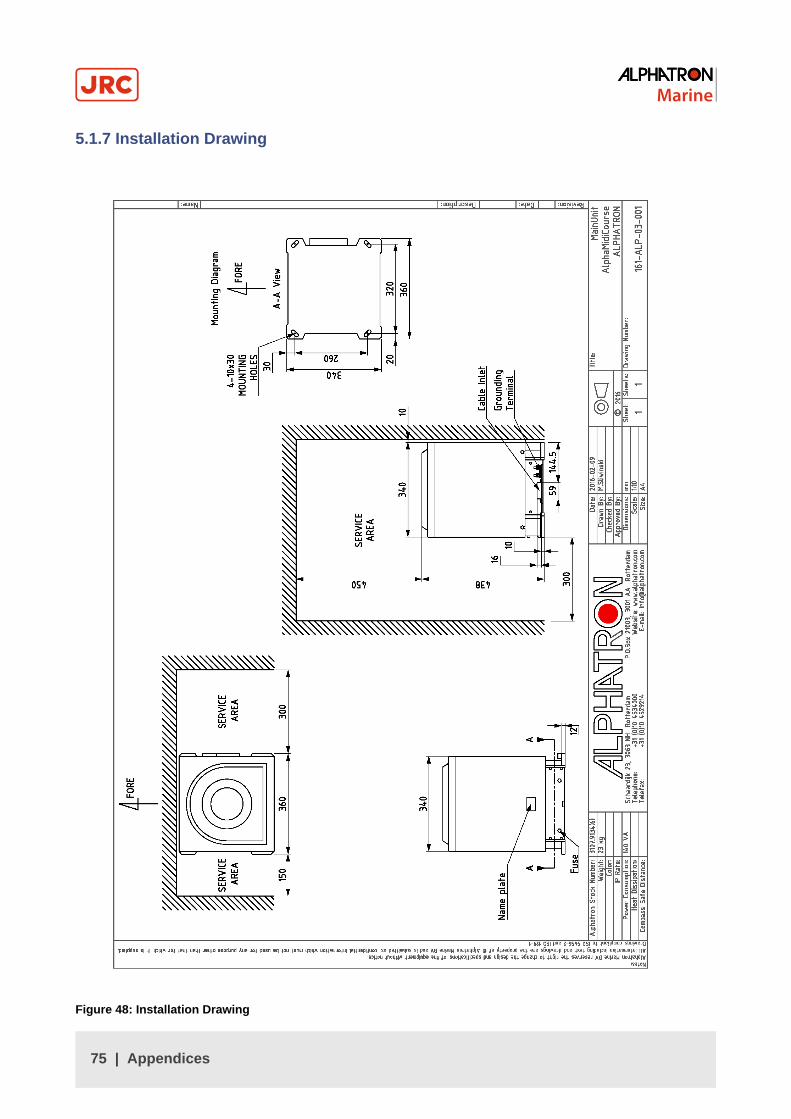
5.1.7 Installation Drawing
Figure 48: Installation Drawing
75 | Appendices

5.1.8 Terminal Board
Figure 49: Terminal Board
76 | Appendices
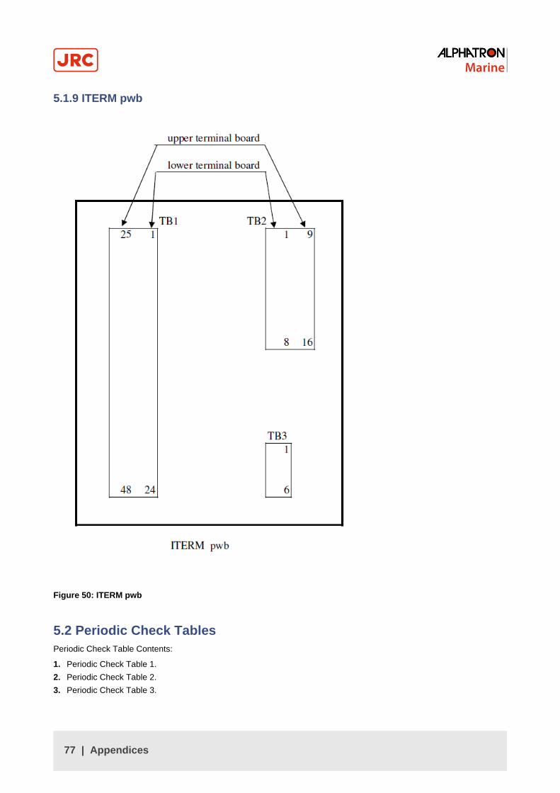
5.1.9 ITERM pwb
Figure 50: ITERM pwb
5.2 Periodic Check TablesPeriodic Check Table Contents:
1. Periodic Check Table 1.
2. Periodic Check Table 2.
3. Periodic Check Table 3.
77 | Appendices

5.2.1 Periodic Check Table 1
Check mark ○ : Normal, △ : Normal after rework or repair
(Example of filling up)Date checked Installation
completed on
'02.06.14Inspector
service engineer
name○○○○
Check items
a. Confirm that the value of each repeatersynchronizes with the displayed true heading on the operating panel.
○
b. Confirm that thedisplayed latitude on the operating panel coincides with the current latitude.
○
c. Measure error with observation if possible. ○
d. Confirm that ship's power supply voltage is stable and within specifications.
○
e. Confirm that all indicators and lamps are lit and it buzzes, when “lamp test” operate.
○
f. Items to be dealt with, and items to be informed.
Periodical Check Table (1)Figure 51: Periodic Check Table 1
78 | Appendices

5.2.2 Periodic Check Table 2
Check mark ○ : Normal,△ : Normal after rework or repair
(example filling in)Date checked Installation
completed on '02.06.14
Inspectorservice
engineer name○○○○
Check items
a. Confirm tightness of fixing screws in mechanical sections and connecting screws in the terminal board. (Re-tighten if loosened.)
○
b. Confirm connecting and wire wearing conditions at connecting wire mounting points and wire bases
○
c. Confirm operating conditions of switches, and displayed state of LEDs and indicators.
○
d. Confirm that warning labels and other indication labels are not dirty or detached. Clean if they become dirty.
○
e. Items to be dealt with, and item to be informed.
Periodical Check Table (2)Figure 52: Periodic Check Table 2
79 | Appendices

5.2.3 Periodic Check Table 3Perform maintenance and check once a year.
Part Name Part No. Interval
Sensitive Element 3107.9152 2 - 3
Brush 3107.9154 2
Step Motor 3107.9158 6
Belt 3107.9160 6
HRZC PWB 3107.9162 6
Inverter PCB 3107.9164 6
Gpower PWB 3107.9170 6
Flexible wire (EAST) 3107.9168 8
Slop Ring 3107.9166 8
Table 20: Maintenance and Check Interval
5.3 Information to be supplied to Alphatron MarineWhen failures can not be corrected on board by the solutions described in this manual, immediately contact AlphatronMarine, or nearest agency in your area, to request advice and supply the following information:
1 Ship's name and owner
2 Equipment name, type and serial no.
3 Where is the ship now?
4 Symptoms failure (Error code/name)
5 When did it occur? Year Month Day Hour
6 Where did it occur? Sea area Channel/River
7 Does it still continue? Continues Intermittently
8 Does it occur repeatedly? Yes Intermittently No
9 Check results
10 Other points observed
11
5.4 AccessoriesThe following accessories may be added to the AlphaMidiCourse:
80 | Appendices
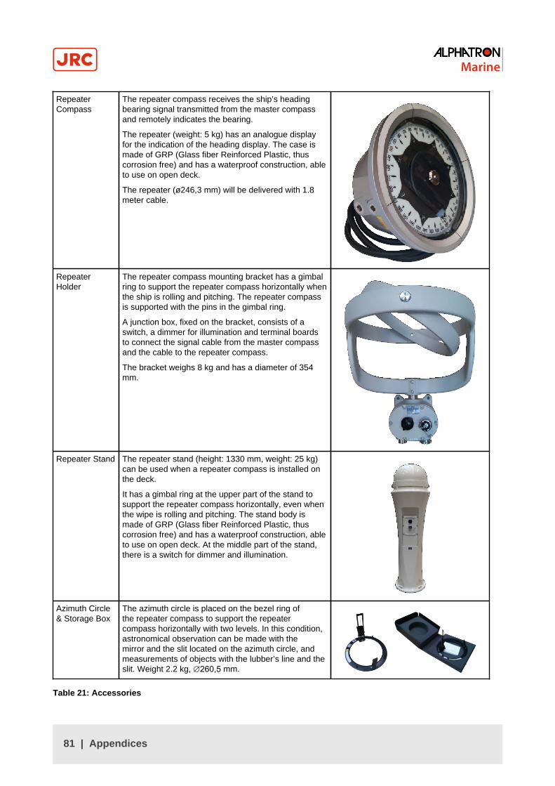
RepeaterCompass
The repeater compass receives the ship’s headingbearing signal transmitted from the master compassand remotely indicates the bearing.
The repeater (weight: 5 kg) has an analogue displayfor the indication of the heading display. The case ismade of GRP (Glass fiber Reinforced Plastic, thuscorrosion free) and has a waterproof construction, ableto use on open deck.
The repeater (ø246,3 mm) will be delivered with 1.8meter cable.
RepeaterHolder
The repeater compass mounting bracket has a gimbalring to support the repeater compass horizontally whenthe ship is rolling and pitching. The repeater compassis supported with the pins in the gimbal ring.
A junction box, fixed on the bracket, consists of aswitch, a dimmer for illumination and terminal boardsto connect the signal cable from the master compassand the cable to the repeater compass.
The bracket weighs 8 kg and has a diameter of 354mm.
Repeater Stand The repeater stand (height: 1330 mm, weight: 25 kg)can be used when a repeater compass is installed onthe deck.
It has a gimbal ring at the upper part of the stand tosupport the repeater compass horizontally, even whenthe wipe is rolling and pitching. The stand body ismade of GRP (Glass fiber Reinforced Plastic, thuscorrosion free) and has a waterproof construction, ableto use on open deck. At the middle part of the stand,there is a switch for dimmer and illumination.
Azimuth Circle& Storage Box
The azimuth circle is placed on the bezel ring ofthe repeater compass to support the repeatercompass horizontally with two levels. In this condition,astronomical observation can be made with themirror and the slit located on the azimuth circle, andmeasurements of objects with the lubber’s line and theslit. Weight 2.2 kg, ∅260,5 mm.
Table 21: Accessories
81 | Appendices

All over the world,close to the customer
JRC/Alphatron Marine B.V.Schaardijk 23 (harbor 115)3063 NH RotterdamThe Netherlands
The information in this document is subject to change without notice anddoes not represent a commitment on the part of Alphatron Marine B.V.
T +31 10 453 4000 Document name : AlphaMidiCourse Document nr. : [email protected] Version : V1.1www.jrc.am © All rights reserved Alphatron Marine B.V.
Centers of ExcellenceHouston, Rotterdam, Singapore, Tokyo