Embed Size (px)
Citation preview
THEALES'S
MICRO SERIESUSER'S GUIDE
FEATURINGNN,trEi,||/I'EE/R'IJ
aJaa-a f - J - a- t -
^rr,trDl'ltt t;rrrlF'D.@aJaa-a tv - l taaa a -! I
A'i',,!E,'|)'F,frJE'aJaaata rv tlltlt -
ft'r|'t'l)EclaJaa-a r l t --
^,I,^Ef)El'/l'�AIIAED@aJaa-a tv-taa al l ' !v-t I
rt'r|l'if1),trrrE ,.',tDaJaa-ra t - v t t - G.tJa.

INTRODUCTIONTHE ALESIS MICRO SERIES
The Essential Signal Processing/Music Production System
MIcRoVERS9I, mlcno LIMITER9MIcRo GATEPMIcRo EQ.MICRO ENHANCERPanO MICRO CUE AMP. Togerher rheyrepresent the culmination of years of research by Alesis to refinethe most musical funct ions of the s ix most essent ia l musicproduction tools into a powerful, integrated system. Each unit iscontained in a compact, cost-effective, interlocking one-third rackspace package - designed for maximum efficiency with minimumhassle.
With the Micro Series in your studio, record quality sounds cannow be achieved. And, of course, all six units are full stereo (withthe exception of MICRO EQ), full bandwidth, and designed forfast, trouble-free operation.
Below you'll find a brief description of each unit, followed bysetup hints and application ideas to help you get the most fromyour gear... so you can get the most from your music.
MICROVERB ll has revolutionized the recording industry byproviding the s ingle most important aspect of music - thecontrol led creat ion of ambience. Ut i l iz ing 16 bi t l inear PCMprocessing, MICROVERB ll places awesome power in the handsof any engineer, f rom 4 track bedroom studio hobbyists toseasoned professionals working in world class recording facilities.
The MICRO LIMITER, a so f t -knee, p rogram-dependentcompressor/limiter, adds punch to vocals and instruments, greatlyimproves the signal to noise ratio of tape recorded tracks, andsmooths out fluctuating dynamics. Attack time and compressionratio adjust automatically so you won't waste valuable timesearching for the most musically correct settings.
The MICRO GATE is a combination noise gate/special effectsprocessor that is useful for eliminating incessant backgroundnoise between musical passages, for creating special effects likegated reverb, and for tightening up loose timing in rhythm tracks.
INTRODUCTION cont'd(especially kick drums and bass guitars). The delay and ratecontrols allow you to set the length of time that the gate staysopen and the slope of the gate as it begins to close.
The MIGRO EO is a 3 band parametric equalizer complete withswi tchab le bandwid th cont ro ls . Per fec t l y su i ted fo r therequirements of stage and studio, the MICRO EQ can be usedwith any electr ic instrument or microphone requir ing tonalalteration.
The MICRO ENHANCER can be thought of as an automaticequalizer, used during tracking and mixdown when you need toadd brilliance to instruments and to restore presence and claritylost in the recording process. And the MICRO ENHANCER doesthis without adding distortion, a problem found in other signalenhancers.
The MICRO CUE AMP is a two channel headphone amplifierthat allows you to expand your headphone monitoring system. ltalso features a second input which can be used with a guitar orkeyboard for private practicing. And you can even chain MICROCUE AMPS together to give you all the additional headphoneoutputs that you need for bigger sessions.
Next time you listen to a great recording, you will very likely behearing the Alesis MICRO SERIES in use. Certainly you shouldbe using all six MICRO SERIES products in your studio and inyour next live performance. This manual will show you how.

ACKNOWLEDGETAENTSFOR lr,ilCRO EA p.37-/oReproduced whh permission ol the publisher, Howard W. Sams and Co. ModernRecording Technioues by Robert E. Runstein copyright 1974.
Reprinted with pemission from the NovemberDecember issue of RecordingEngineer/Pmducer. @yright 1 972, Intertec Publishing Corporalion, OvedandPark, Kansas.
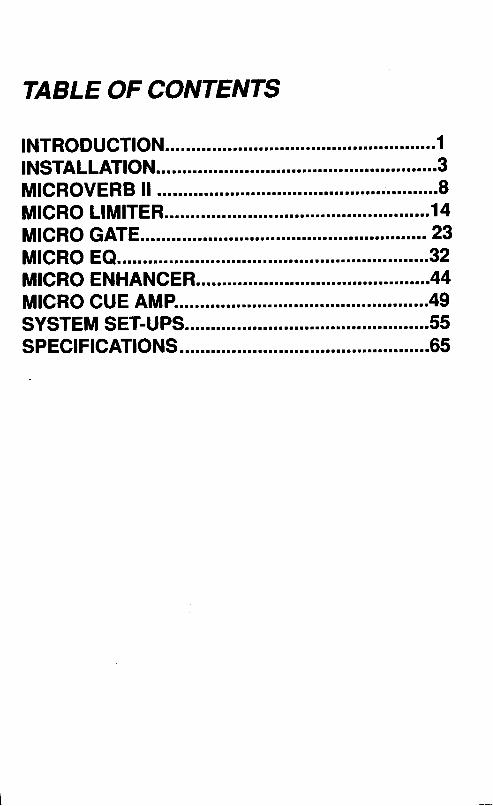
TABLE OF CONTENTS
INSTALLATIONBefore unpacking your new Alesis MlcRo sERlEs unit, take a
moment to look through this instruction manual. we've made itbrief and informative and it will answer any questions that youmight have. some helpful setup thoughts are inctuded along withsome application hints for each unit.
Each MlcRo sERlEs unit is designed and engineered to giveyou the highest level of professional performance and quatity.we've made each unit musical and easy to use so that you canget the most from your music with the least amount of effort.
lnstruments, MicrophonesThe Alesis MlcRo SERIES has high impedance inputs that are
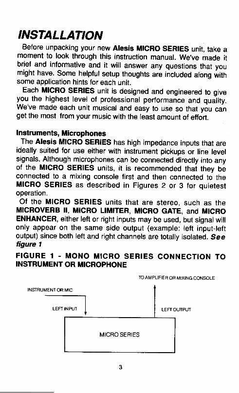
ideally suited for use either with instrument pickups or line levelsignals. Although microphones can be connected direcily into anyof the MICRO SERIES units, it is recommended that they beconnected to a mixing console first and then connected to theMfCRO SERIES as described in Figures 2 or 3 for quietestoperation.Of the MICRO SERIES units that are stereo, such as the
MICROVERB ll, MICRO LIMITER, MTCRO GATE, and MTCROENHANCER, either left or right inputs may be used, but signalwillonly appear on the same side output (example: left input-leftoutput) since both lett and right channels are totally isolated. Seetigure 1
FIGURE 1 - MONO MICRO SERIES CONNECTION TOINSTRUMENT OR MICROPHONE
INSTRUMENTOR
TO AMPLIFIER OR MIXING CONSOLE
LEFT OUTPUT
INSTALLATION cont'dThis is NOT true of the MICROVERB ll, however' lf the left input
only of the MICROVERB ll is used, the input signal will appear asmono (present in both channels) at the dry side of the mix control'
Mixing ConsotesAll of the MICRO SERIES units can handle mono or stereo
sends at all system levels. The input circuitry of the MICROSERIES can easily handle +4dBv levels (+20dBv peaks), whilehaving enough input or output gain to interface with the extremelylow signal levels of budget recording systems.
The MICRO SERIES units may be connected to the mixingconsole in several ways.
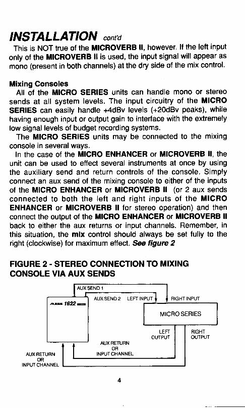
In the case of the MICRO ENHANCER or MICROVERB ll, theunit can be used to effect several instruments at once by usingthe auxil iary send and return controls of the console. Simplyconnect an aux send of the mixing console to either of the inputsof the MICRO ENHANCER or MICROVERB ll (or 2 aux sendsconnected to both the lef t and r ight inputs of the MICROENHANCER or MICROVERB ll for stereo operation) and thenconnect the output of the MlcRo ENHANCER or MICROVERB llback to either the aux returns or input channels. Remember, inthis situation, the mix control should always be set fully to theright (clockwise) for maximum effect. See figure 2
FIGURE 2. STEREO CONNECTION TO MIXINGCONSOLE VIA AUX SENDS
AUXSEND2 LEFTINPUT RIGHT INPUTrry1622m
MICRO SERIES
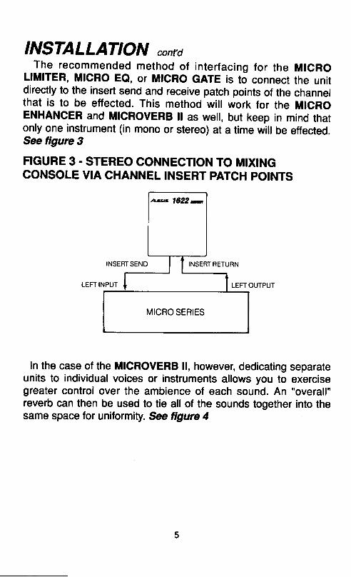
INSTALLATION contdThe recommended method of interfacing for the MIGRO
LlMlrER, MlcRo EQ, or MlcRo GATE is to connect the unitdirectly to the insert send and receive patch points of the channelthat is to be effected. This method will work for the MlcRoENHANCER and MICROVERB ll as well, but keep in mind thatonly one instrument (in mono or stereo) at a time will be effected.See tigure 3
FIGURE 3. STEREO CONNECTION TO MIXINGCONSOLE VIA CHANNEL INSERT PATCH POINTS
INSERT SEND INSERT RETURN
LEFT OUTPUT
ln the case of the MICROVERB ll, however, dedicating separateunits to individual voices or instruments allows you to exercisegreater control over the ambience of each sound. An "overall"reverb can then be used to tie all of the sounds together into thesame space for uniformity. See figwe 4
as 1622 u
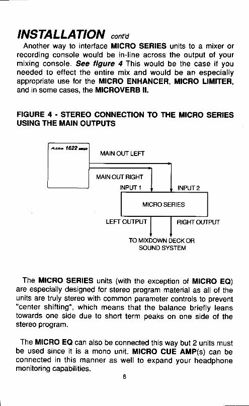
INSTALLATION cont'dAnother way to interface MICRO SERIES units to a mixer or
recording console would be in-l ine across the output of yourmixing console. See figure 4 This would be the case if youneeded to effect the entire mix and would be an especiallyappropriate use for the MICRO ENHANCER, MICRO LIMITER,and in some cases, the MICROVERB ll.
FIGURE 4 - STEREO CONNECTION TO THE MICRO SERTESUSING THE MAIN OUTPUTS
MAIN OUT LEFT
LEFT OUTPUT RIGHTOUTPUT
The MICRO SERIES units (with the exception of MTCRO Ee)are especially designed for stereo program material as all of theunits are truly stereo with common parameter controls to prevent"center shift ing", which means that the balance briefly leanstowards one side due to short term peaks on one side of thestereo program.
The MICRO EQ can also be connected this way but 2 units mustbe used since it is a mono unit. MIGRO CUE AMP(s) can beconnected in this manner as well to expand your headphonemonitori ng capabilities.
6
a'*.'1622re
MICRO SERIES
INSTALLATION cont'd
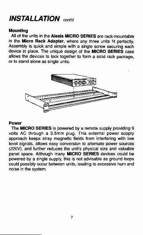
MountingAll of the units in the Alesis MICRO SERIES are rack-mountable
in the Micro Rack Adapter, where any three units fit perfectly.Assembly is quick and simple with a single screw securing eachdevice in place. The unique design of the MICRO SERIES caseallows the devices to lock together to form a solid rack package,or to stand alone as single units.
PowerThe MIGRO SERIES is powered by a remote supply providing 9
volts AC through a 3.5mm plug. This external power supplyapproach keeps stray magnetic fields from interfering with lowlevel signals, allows easy conversion to alternate power sources(220V), and further reduces the unit's physical size and valuablepanel space. Although many MICRO SERIES devices could bepowered by a single supply, this is not advisable as ground loopscould possibly occur between units, leading to excessive hum andnoise in the system,
MICROVERBYI
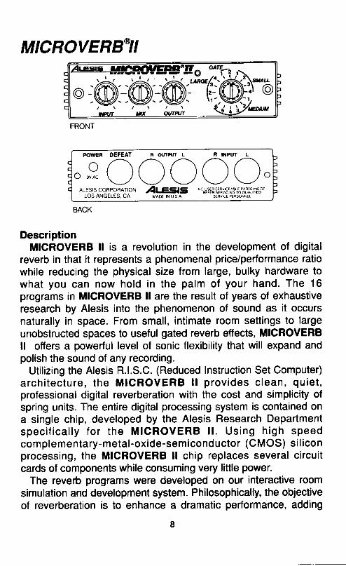
DescriptionMICROVERB ll is a revolution in the development of digital
reverb in that it represents a phenomenal price/performance ratiowhile reducing the physical size from large, bulky hardware towhat you can now hold in the palm of your hand. The 16programs in MICROVERB ll are the result of years of exhaustiveresearch by Alesis into the phenomenon of sound as it occursnaturally in space. From small, intimate room settings to largeunobstructed spaces to useful gated reverb effects, MICROVERBll offers a powerful level of sonic flexibility that will expand andpolish the sound of any recording.
Utilizing the Alesis R.l.S.C. (Reduced Instruction Set Computer)a rch i tec tu re , the MICROVERB l l p rov ides c lean, qu ie t ,professional digital reverberation with the cost and simplicity ofspring units. The entire digital processing system is contained ona single chip, developed by the Alesis Research Departments p e c i f i c a l l y f o r t h e M l c R o v E R B l l . U s i n g h i g h s p e e dcomplementary-metal-oxide-semiconductor (CMOS) si l iconprocessing, the MICROVERB ll chip replaces several circuitcards of components while consuming very little power.
The reverb programs were developed on our interactive roomsimulation and development system. Philosophically, the objectiveof reverberation is to enhance a dramatic performance, adding
zlr-sts ltlGlllllrEEtZ" aE-z .\
.@: @@T@mPOWEN DEFEAT R (X
o a - \\ - / ( l { } ( ) ( t to nuoc
\_/ \-/ \-/ \_/ \-/ o
ALESlscoRpoRATroN )t ee25 *#tE1::8yi8.,,j8.,.""6,11i,ilrt6".LOS ANGELES, CA MADE rN u s a SEBVcE PERSoNNEL
MICROVERBYI contdspace, power, and depth. Natural spaces tend to sound morepleasing than the simulated reverb types such as springs andplates, and for this reason, we use room terminology in desiribingour programs. The programs cover a wide range of sizes andqualit ies, and include such unnatural concepti as gated andreverse types.
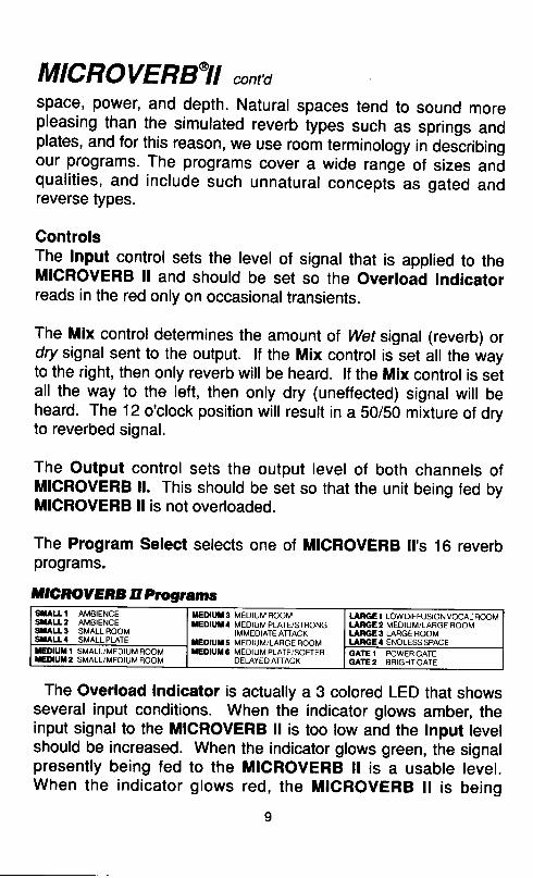
ControlsThe Input control sets the level of signal that is applied to theMlcRovERB ll and should be set so the overload Indicatorreads in the red only on occasionaltransients.
The Mix control determines the amount of wet signal (reverb) ordqy signal sent to the output. lf the Mix control is set all the wayto the right, then only reverb will be heard. lf the Mix control is setall the way to the left, then only dry (uneffected) signat will beheard. The 12 o'clock position will result in a 50/50 mixture of dryto reverbed signal.
The Output control sets the output level of both channels ofMICROVERB ll. This should be set so that the unit being fed byMICROVERB ll is not overloaded.
The Program Select selects one of MICROVERB ll's 16 reverbprograms.
ntCnOYERBllProgramsSIALLI AMBIENCESXALL2 AMBIENCESTALL3 SMALLROOMSIALT' SMAI I PI ATF
TEDIUU3 MEDIUMROOMTEDIUT' MEDIUM PLATEi STRONG
IMMEDIATE ATTACKTEDIUT5 MEDIUM/LARGE ROOMT€OIUX 6 MEDIUM PLATE/SOFTER
DELAYED ATTACK
LANGE 1 LOW DIFFUSION VOCAI ROOMLARGE2 MEDIUM/LARGE ROOMLARGE3 LARGE ROOMLANGE4 ENDLESSSPACE
ED|UT T SMALL/MEOIUM ROOMTEDIUT2 SMALL/MEOIUM ROOM
GATE.I POWERGATEGAT€2 BRIGHTGATE
The Overload Indicator is actually a 3 colored LED that showsseveral input conditions. When the indicator glows amber, theinput signal to the MICROVERB ll is too low and the lnput levelshould be increased. When the indicator glows green, the signalpresently being fed to the MICROVERB ll is a usable level.When the indicator glows red, the MICROVERB ll is being
MICROVERBYI contdoverloaded and the Input control should be decreased.
The Bypass Jack, located on the rear panel, bypasses thereverb signal and allows only the dry signal at the outputs. AnySPST type footswitch (such as the reverb footswitch thatsometimes comes with amplifiers) will work for this function.
OperationMICROVERB ll is easy to use in almost any application. Simply
do the following:1. Apply a signal to either the left input jack for mono (used with
a single instrument), or both left and right jacks for stereo.2. Increase the Input control until the ReC LED briefly lights
on occasional program peaks. The LED should remain "green"
most of the time. This indicates that there is sufficient level tomaintain a good signal to noise ratio.
3. Increase the Output control until there is sufficient outputlevel.
4. Adjust the Mix control until the desired ratio of dry to wets igna l i s ach ieved. REMEMBER: ln cases were theMTCROVERB lt is used with the aux sends of a recordingconsole, the Mix control should remain allthe way to the right (ailwet signal).
5. Select your program of choice.
As a good rule of thumb for select ing programs, rhythmicinstruments such as drums and instruments with ostinato (quicklyrepeating) type patterns usually work best with smaller programs.Long melodic lines and pads generally sound better with largerrooms. Remember, however, that this is only a starting point. Useyour ears and select the program that sounds best to you!
How to use MICROVERB ll in your studioThe 16 programs in MICROVERB ll offer a wide range of
ambient spaces. lts compact, atfordable format means that eventhe smallest 4 track studio can own more than one MIGROVERBll. One of the greatest differences between home recordings and
1 0

MICROVERBYI contdtop flight record productions is in the quality and number of highperformance reverb processors. Simply stated, the big studioshave a lot of digital reverbs and the smaller studios usually don't.MICROVERB ll changes ail that.
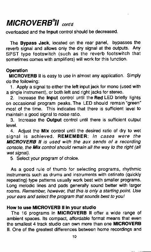
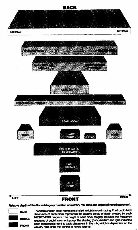
The illustration shows a typical reverb assignment for a no hotds barred record pro-duction. while this setup may not represent the capabilities of your own recordingefforts, it does illustrate why modern recordings sound so spacioui and dramatic. Th616 bit processor in MlcRor/ERB II allorvs you to create this sense of space with crystal-line clarity and great resolution.
These programs were chosen for the purpose of creating a 'sound stage' for themusical performance. There is a well defined sense of three dimensional space that isoccupied by each instrument: left to right and front to back. The blocks in the illustrationindicate the physical placement of each instrument, and the spreading of the sounddue to the psychoacoustic imaging characteristics of each program. Notice that thesmall programs have more of a centered spatial image while the large programs arewider, more open and spacious.
Recornmended progralrs are listed by number nelit to each instrument. These pro-gram suggestions are based on current popular uses of digital rwerb, but use yor imagFption_q1d please experiment. Musical style, personal taste and creativity are 1rcur guid-e-lines. This mix uses I MlcRovERB II programs simultaneously. The attoroaoifity otMICROVERB Ileasily brings at least a portion of this mixwithin the reach of a//studios.
The mix control settings apply to either the mix control on MICRoVERB II lor standalone operation, or the settings can apply to the sends and receives of a mixing con-sole. IMPoRTANT! when used with the sends and receives of a mixing console thb mixcontrol on MIORoVERB II should a lways be set fully clockwise, and the returns on theconsole panned hard left and right for the full stereo effect.
UIXCONTROLPROGRAT %Dty % h
SNAREDRUM . GATEI oT2L E A O V O C A L . . . . . . . . M E D I U M 4 O R L A R G E 1 6 0BACKGROUNDVOCAIS .. . . . . . MEDIUMsLEAD INSTRUMENTS (guitiar, sax, svnth, etc.) LARGE 1RHYTHMGUfTARANDKEYBOARDS... . . SMALLlor2 so-o 50-100HORNSECTION. . . , , .ARGE2 40-50STRINGS LARGE 1 50-10()PERCUSSIONANDCYMBALS. .. LARGEl OR
MEDIUM 2
BASSGUITAR.. . SMALL2H 1 H 4 T . . . . . . . . . . . . . S M A L L T o r 2
11
Mtffi
II.IIfiNTil
-^--
W-
Rcldrlr dcFr otttp Soundd{p(afurcdon dwcudy nh reUo ild d.ill ot ltvub pogrrn}
l-l o* Thewithof €dlHod<rcprcen0stplefr btit*sbr€oi.ttEFg.Thefiontbbad(dimersirn d each blod( represents fre rclalirre serce cf deptt ct€aied by €a.tl
I.-,' HHT3ffiffiS'#ffi.ffi'ffiffiI *tr
mbqwtidrbdePedentmthe
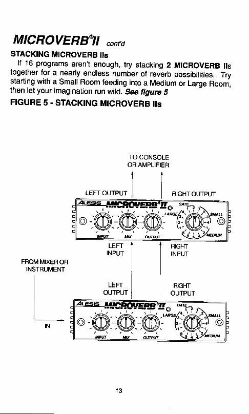
MICROVERBYI cont,dSTACKING MICROVERB ils
lf 16 programs aren't enough, try stacking 2 MrcRovERB ilstogether for a nearly endless number of revbrb possibilities. Trystarting with a small Room feeding into a Medium or Large Room,then let your imagination run wild. See ligure 5FIGURE 5. STACKING MICRoVERB IIs
TO CONSOLEOR AMPLIFIER
t lIrcrr oureur | |
FROM MIXER ORINSTRUMENT
N
RIGHTOUTPUT
*#ffih-a"@:.@:-.@i*'6j@?/ \ / \ / \ S - _ , I
1 3
MICRO LIMITER'
BACK
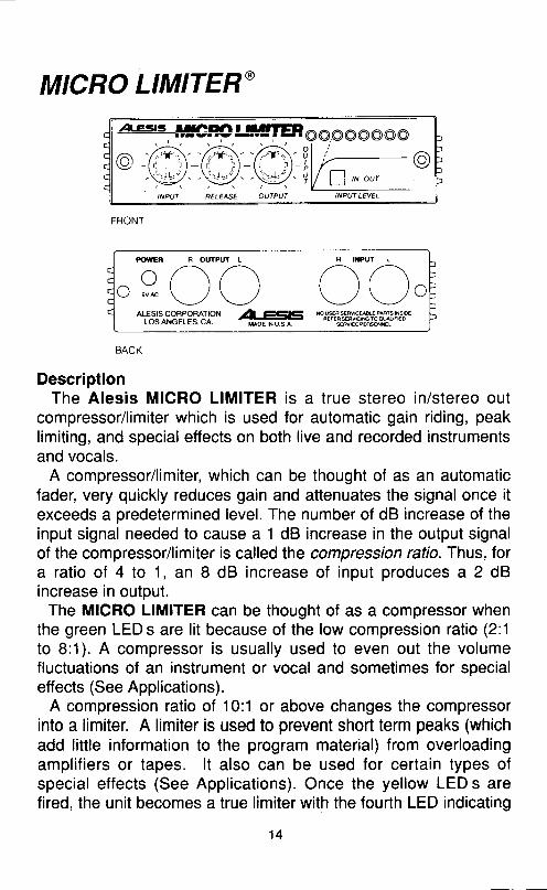
DescriptionThe Alesis MICRO LIMITER is a t rue stereo in/stereo out
compressor/limiter which is used for automatic gain riding, peaklimiting, and special effects on both live and recorded instrumentsand vocals.
A compressor/limiter, which can be thought of as an automaticfader, very quickly reduces gain and attenuates the signal once itexceeds a predetermined level. The number of dB increase of theinput signal needed to cause a 1 dB increase in the output signalof the compressor/limiter is called the compression rafio. Thus, fora ratio of 4 to 1, an 8 dB increase of input produces a 2 dBincrease in output.
The MICRO LIMITER can be thought of as a compressor whenthe green LED s are lit because of the low compression ratio (2:1to 8:1). A compressor is usually used to even out the volumefluctuations of an instrument or vocal and sometimes for specialeffects (See Applications).
A compression ratio of 10:1 or above changes the compressorinto a limiter. A limiter is used to prevent short term peaks (whichadd little information to the program material) from overloadingamplif iers or tapes. lt also can be used for certain types ofspecial effects (See Applications). Once the yellow LED s arefired, the unit becomes a true limiter with the fourth LED indicating
POWEN R OulPUI L
r-\{ ) { )
\-/ svrc \ ,/ \ ,/
"f&1R'"?tPS:^"'l"r 4#F *"?r+HilFAmUi'A:tr
1 4
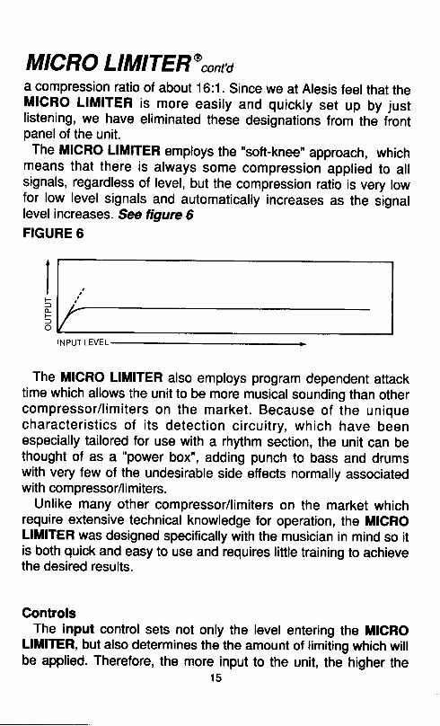
MICRO LIMITER@contda compression ratio of about 16:1. since we at Alesis feel that theMICRO LIMITER is more easily and quickty set up by justlistening, we have eliminated these designations from the frontpanel of the unit.
The MICRO LIMITER employs the "soft-knee" approach, whichmeans that there is always some compression applied to allsignals, regardless of level, but the compression ratio is very lowfor low level signals and automatically increases as the signalfevel increases. See figure 6FIGURE 6
5Flo
INPUT LEVEL
The MICRO LIMITER also employs program dependent attacktime which allows the unit to be more musical sounding than othercompressor/ l imi ters on the market. Because of the uniquecharacter ist ics of i ts detect ion c i rcui t ry, which have beenespecially tailored for use with a rhythm section, the unit can bethought of as a "power box", adding punch to bass and drumswith very few of the undesirable side effects normally associatedwith compressor/limiters.
Unlike many other compressor/limiters on the market whichrequire extensive technical knowledge for operation, the MICROLIMITER was designed specifically with the musician in mind so itis both quick and easy to use and requires little training to achievethe desired results.
ControlsThe input control sets not only the level entering the MICRO
LllllTER, but also determines the the amount of limiting which willbe applied. Therefore, the more input to the unit, the higher the
1 5
MICRO LIMITER@cont'dcompression ratio. This ratio is indicated by the input LED's inconjunction with the graph on the front of the unit.
The release time control determines how quickly the l imiterrecovers from a signal applied to the input. Farthest to the left isthe fastest release time while full to the right is the slowest.
The output control is provided for matching levels so that nosignal level is lost due to the effects of limiting.
An in/out switch allows you to bypass the MIGRO LIMITER forcomparison purposes, if necessary.
OperationAlthough specific operation of the MICRO LIMITER will vary per
instrument or effect desired, basic operation of the MICROLIMITER is the same. First, apply a signal to the unit's right or leftinput jack (or both jacks for stereo), taking care to use the sameside for the output. Depress the in/out switch to the "in" position.
To determine the right amount of limiting, it is best to look at themeters on your console or tape machine and listen to the results.This is covered more in the next section (see application). Beaware that too much limiting will cause the program material toseem dulland lifeless.
Next, adjust the release time by starting with the control full tothe left (counterclockwise). This is the most critical adjustment soit must be made carefully for best results. As a general rule,signals that are percussive or have a high treble content (likedrums) should have a shorter release time, or the control setmore to the left. Program that contains a lot of low frequencies(like bass) should have a longer release time, or the control setmore to the right.
Care should be taken when the release control is set too far tothe left (release time too short) as this setting may result in a
MICRO LIMITER@contdslight amount of harmonic distortion. Also, a phenomena called"pumping" or "breathing" might occur. This means that if a rapidsuccession of peaks were fed into the limiter (a staccato guitar orsynth part, for instance), the limiter would respond to each peak ofthe signal, causing a rapid rise in background noise as the gain isincreased after each peak. Both of these conditions are a by-product of the limiting process and can occur with any limiter.However, these conditions may never occur during your particularuse as they are dependent on the type of instrument fed into theMICRO LIMITER, and the style of music played, as well as thesetting of the release control. Simply turn the release control abit to the right and either the slight distortion or "pumping" and"breathing" will go away!
lf the release control is set too far to the right (release time toolong), the program may sound dull and l ifeless as a result ofsquashed dynamics. When in doubt as to how to set the releasecontrol, it's better to keep it on a shorter setting (towards the left)since fhe MICRO LIMITER is most forgiving in operation at thispoint and you will most likely get the desired results.
Finally, set the output control by switching the in/out control in,then out, and adjust the output control until the level is the sameregardless of the position of the switch.
ApplicationThe MICRO LIMITER can be made to perform several differentfunctions, depending upon control settings. These are:
1. Even out the volume differences between registers oninstruments. An example of this would be that some bass guitarstrings are louder than others on some instruments. The use of aMICRO LIMITER produces a smoother bass line by matching thevolumes of the different notes.
2 . Min imize the changes in vo lume when a voca l i s t o rinstrumentalist momentarily changes his distance from the mike.
1 7
MICRO LIMITER@cont'd3. Allow an instrument to be recorded hotter onto tape by
preventing transients (high level peaks) from pinning the meter.
4. Make a vocal or instrument "sit" better in the mix bydecreasing the signal peaks and increasing the lower volumeparts. This actually enables the signal to be made significantlylouder in the mix while increasing the overall signal level meteronly slightly
5. lncrease the "punch" of certain instruments such as bass ordrums, by allowing the peak portion of the signal through whilelimiting the rest.
6. lncrease the sustain of an instrument such as electric guitarby compressing its dynamic range.
7. Stop distortion due to temporary overloading by controllingtransients.
In the examples below, we can bypass the normal technicalexplanations by simply watching the meters and listening. Thiswill get you the best results from your MICRO LIMITER with theleast amount of hassle.
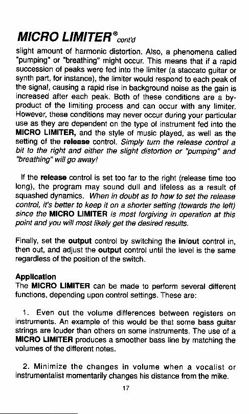
MICRO LIMITER for adding punch to an instrumentAdjust the input control until the instrument (or instruments)
begins to brighten on the attack portion of the signal. This shouldbe at about the first red LED. Be careful not to limit the signal toomuch as it will start to become very dull and lifeless. Also, becareful as to the setting of the Release control (Remember: morebass = longer setting). The MICRO LIMITER, unlike any otherlimiter on the market, is optimized for rhythm section work (bassand drums) allowing you to add the maximum punch whilekeeping undesirable side effects to a minimum. See figure 7
1 8
MICRO LIMITER@cont,dFIGURE 7FROM INSTRUMENT OR MIXING CONSOLE
LEFT INPUT t
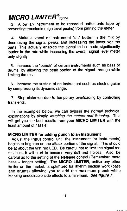
MICRO LIMITER for adding sustain for electric guitarAdjust the Input control until the instrument ',snaps" on the
attack portion of the signal. Now increase the Release controluntil the desired amount of sustain is achieved (this may be all theway to the right). See figure I
FIGURE 8GUITAR
LEFr f'rpur ]
TOAMPLIFIER OR MIXING CONSOLE
TO AMPLIFIER OR MIXING CONSOLE
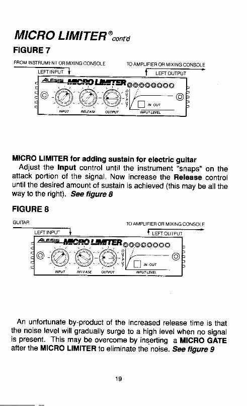
An unfortunate by-product of the increased release time is thatthe noise level will gradually surge to a high level when no signalis present. This may be overcome by inserting a MICRO GATEafter the MfCRO LIMITER to eliminate the noise. See tigure g
1 9
LEFT INPUT
MICRO LIMITER@cont'dFIGURE 9GUITAR
LEFT OUTPUT
TO AMPLIFIER OR MIXING CONSOLE
Another possible by-product of increased release time is that theinput s ignal may become dul l due to fact that the MICROLIMITER continues to hold on to a note while the next one isplayed, which prevents t ransients f rom making i t through.However, with the addition of a MICRO ENHANCER after yourMICRO LIMITER and MICRO GATE you have the perfect setupfor long, sustaining guitar! *e figure 10
20

MICRO LIMITER@cont,dFIGURE 1OGUITAR
LEFT INPUT
MICRO LIMITER for controll ing level of an instrument orvocalWith the in/out switch in the "out" position, watch the VU or level
meter, and/or listen to the differences in volume between notes.The VU or level meter will show a large amount of movement.Now switch IrllCRO LIMITER into the circuit and begin to increasethe Input control until the notes allsound relatively the same, andthe level meter is reacting less wildly to the signal. The metershould be moving somewhat, since if it stays in one position thenit would be an indication that the signal is becoming overlimited
TO AMPLIFIER OR MIXING CONSOLE
21
MICRO LIMITER@cont'dand will lack dynamics.
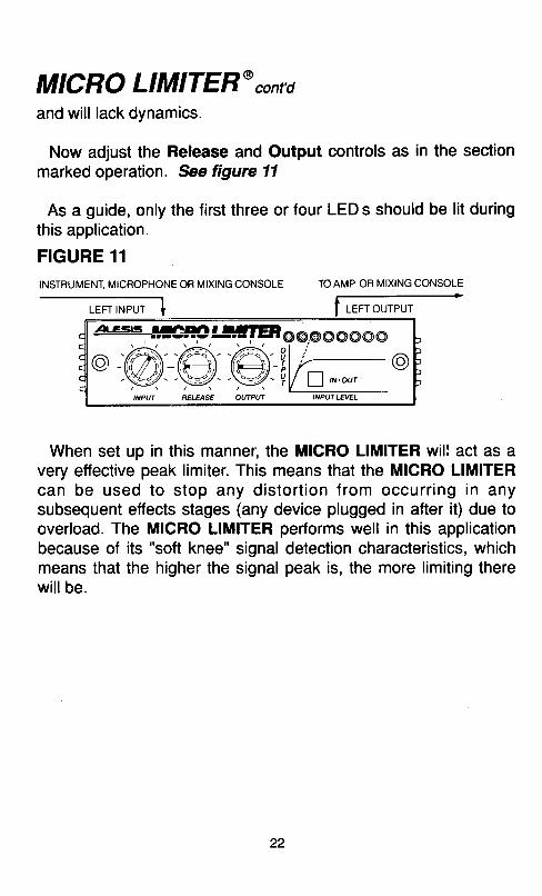
Now adjust the Release and Output controls as in the sectionmarked operation. See tigure 11
As a guide, only the first three or four LED s should be lit duringthis application.
FIGURE 11
INSTRUMENT. MICROPHONE OR MIXING CONSOLE
,-*r*- 1
When set up in this manner, the MICRO LIMITER will act as avery effective peak limiter. This means that the MICRO LIMITERcan be used to stop any distort ion f rom occurr ing in anysubsequent effects stages (any device plugged in after it) due tooverload. The MIGRO LIMITER performs well in this applicationbecause of its "soft knee" signal detection characteristics, whichmeans that the higher the signal peak is, the more limiting therewi l lbe .
TOAMP OR MIXING CONSOLE
LEFT OUTPUT
22
MICRO GATE'
BACK
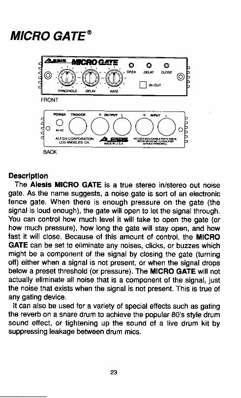
DescriptionThe Alesis MICRO GATE is a true stereo in/stereo out noise
gate. As the name suggests, a noise gate is sort of an electronicfence gate. When there is enough pressure on the gate (thesignal is loud enough), the gate will open to let the signal through.You can control how much level it will take to open the gate (orhow much pressure), how long the gate will stay open, and howfast it will close. Because of this amount of control, the MICROGATE can be set to eliminate any noises, clicks, or buzzes whichmight be a component of the signal by closing the gate (turningoff) either when a signal is not present, or when the signal dropsbelow a preset threshold (or pressure). The MICRO GATE will notactually eliminate all noise that is a component of the signal, justthe noise that exists when the signal is not present. This is true ofany gating device.
It can also be used for a variety of special etfects such as gatingthe reverb on a snare drum to achieve the popular 80's style drumsound effect, or tightening up the sound of a live drum kit bysuppressing leakage between drum mics.
FRONT
POWEN ?RGGER R OUTA'' L R NruT L
o .-\v ( r ( ) ( ) ( ) (u '�vrc \*_-,/ \_/ \_/ \_/ \,
o
ALE^s.ls_co^BpoFAIoru -a-.815 *#f*Effi.#ffff iLTxLOSANGELES.CA. - i l ioe, luse *turE*FsNEL
23
MICRO GATEtcont'dControlsThe Threshold control sets the point at which the MICRO GATE
will open (let the signal through). Turning this control clockwise (tothe right) lowers the threshold point, making the gate easier totrigger.
The Rate control determines how fast the MICRO GATE willclose, with the fastest position being all the way to the right(clockwise). This can also be thought of as a release time control.
A Delay control allows the user to determine how long theMICRO GATE will wait before closing after a signal has droppedbelow the threshold.
A series of colored LED s are also included to indicate thecurrent status of the MICRO GATE. A red "Close" LEDindicates that the gate is closed and no signal is being allowedthrough. A green "Open" LED indicates the the gate is open,having risen above the threshold point, and signal is f lowingfreely through the unit. The yellow "Delay" LED indicates that thesignal has dropped below threshold and the MICRO GATE iswaiting for a period of time (determined by the delay control)before closing.An External Trigger input can also be found on the rear panel.
This input is sometimes called a "key" input. The function of theExternal Trigger input is to allow the MICRO GATE to open bybeing triggered from a source other than the one plugged into theinputs. An example of this is when an instrument track (such as akeyboard), which has been played with imprecise rhythm, can betightened up and the track saved by triggering (or "keying") fromanother instrument which was played with more precise time. lnthis case, the output of the snare drum track is plugged into theTrigger Input of the MICRO GATE which then has the keyboardtrack plugged into its normal inputs. Every time the snare drumhits, the gate wil l open allowing the sound of the keyboardthrough in perfect sync. The length of time that the keyboardstays on will be determined by adjusting both the Rate and Delay
24
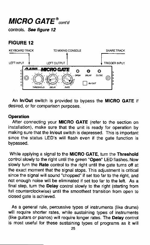
MICRO GATEtcont'dcontrofs. See figure 12
FIGURE 12KEYBOARD TRACK
An In/Out switch is provided to bypass the MICRO GATE ifdesired, or for comparison purposes.
OperationAfter connecting your MICRO GATE (refer to the section on
installation), make sure that the unit is ready for operation bymaking sure that the in/out switch is depressed. This is importantsince the status LED's wil l f lash even if the gate function isbypassed.
While applying a signal to the MICRO GATE, turn the Thresholdcontrol slowly to the right until the green "Open" LED flashes. Nowslowly turn the Rate control to the right until the gate turns off atthe exact moment that the signal stops. This adjustment is criticalsince the signal will sound "chopped" if set too far to the right, andnot enough noise will be eliminated if set too far to the left. As afinal step, turn the Delay control slowly to the right (starting fromfull counterclockwise) until the smoothest transition from open toclosed gate is achieved.
As a general rule, percussive types of instruments (like drums)will require shorter rates, while sustaining types of instruments(like guitars or pianos) will require longer rates. The Delay controlis most useful for these sustaining types of programs as it will
25
SNARE TRACK
I rnrooe n rxeur
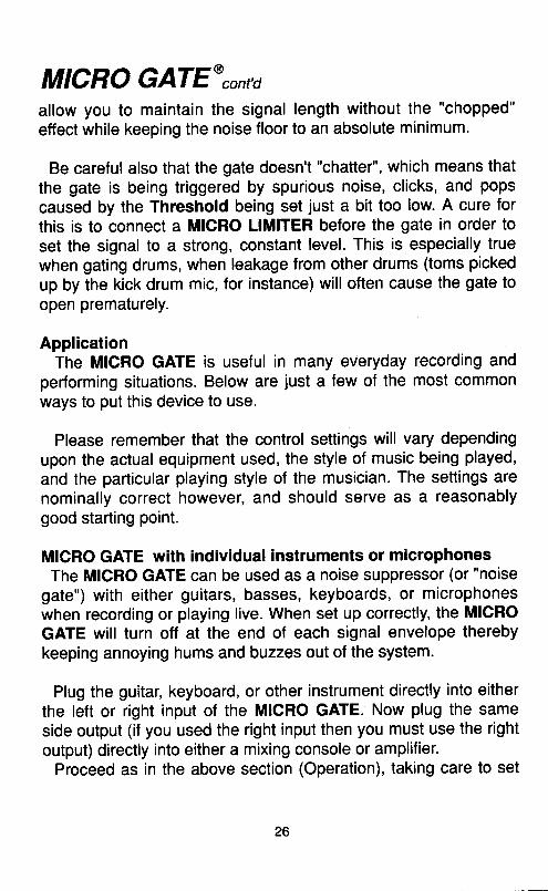
MICRO GATE@"ont'aallow you to maintain the signal length without the "chopped"
effect while keeping the noise floor to an absolute minimum'
Be careful also that the gate doesn't "chatter", which means thatthe gate is being triggered by spurious noise, clicks, and popscaused by the Threshold being set just a bit too low. A cure forthis is to connect a MICRO LIMITER before the gate in order toset the signal to a strong, constant level. This is especially truewhen gating drums, when leakage from other drums (toms pickedup by the kick drum mic, for instance) will often cause the gate toopen prematurely.
ApplicationThe MICRO GATE is useful in many everyday recording and
performing situations. Below are just a few of the most commonways to put this device to use.
Please remember that the control settings will vary dependingupon the actual equipment used, the style of music being played,and the particular playing style of the musician. The settings arenominally correct however, and should serve as a reasonablygood starting point.
MICRO GATE with individual instruments or microphonesThe MICRO GATE can be used as a noise suppressor (or "noise
gate") with either guitars, basses, keyboards, or microphoneswhen recording or playing live. When set up correctly, the MIGROGATE will turn off at the end of each signal envelope therebykeeping annoying hums and buzzes out of the system.
Plug the guitar, keyboard, or other instrument directly into eitherthe left or right input of the MICRO GATE. Now plug the sameside output (if you used the right input then you must use the rightoutput) directly into either a mixing console or amplifier.
Proceed as in the above section (Operation), taking care to set
26
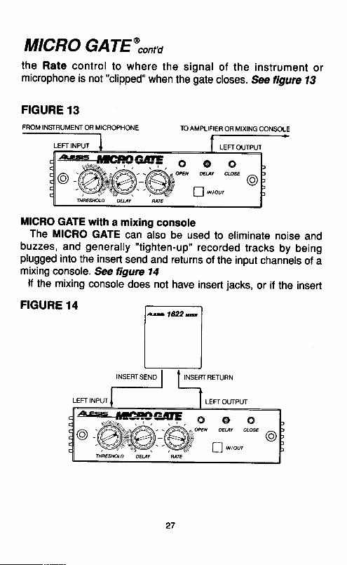
MICRO GATE@,onrathe Rate control to where the signal of the instrument ormicrophone is not "clipped" when the gate closes. See tigure l3
I
FIGURE 13FROM INSTRUMENT OR MICROPHONE
LEFT INPUT
TO AMPLIFIER OR MIXING CONSOLE
LEFTOUTPUT
MICRO GATE with a mixing consoleThe MICRO GATE can also be used to eliminate noise and
buzzes, and generally "tighten-up" recorded tracks by beingplugged into the insert send and returns of the input channels of amixing console. Se tigure 14
lf the mixing console does not have insert jacks, or if the insert
FIGURE 14
INSERT SENO INSERT RETURN
LEFT INPUT LEFT OUTPUT
ats16122n
27
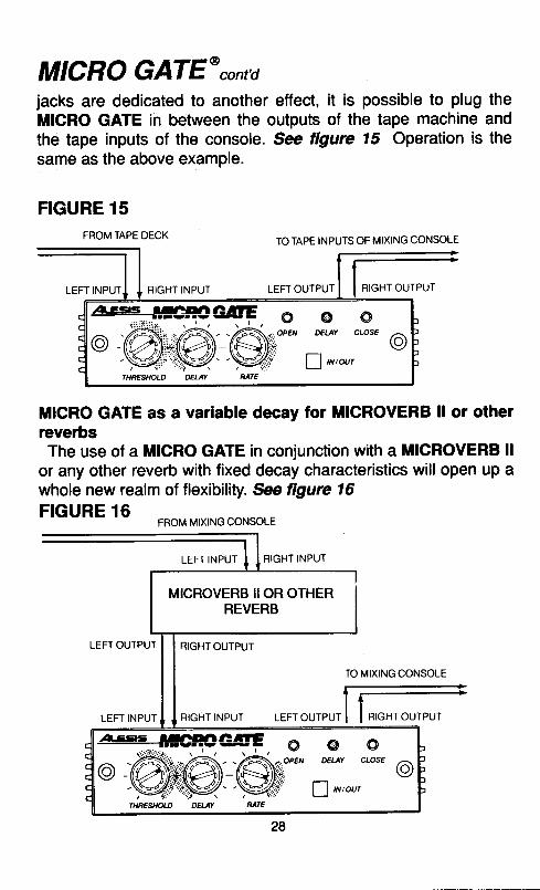
MICRO GATE'cont'djacks are dedicated to another effect, it is possible to plug theMICRO GATE in between the outputs of the tape machine andthe tape inputs of the console. See figure 15 Operation is thesame as the above example.
FIGURE 15FROM TAPE DECK
TO TAPE INPUTS OF MIXING CONSOLE
LEFT INPUI RIGHT INPUT LEFT OUTPUT RIGHT OUTPUT
MICRO GATE as a variable decay for MICROVERB ll or otherreverbsThe use of a MICRO GATE in conjunction with a MICROVERB ll
or any other reverb with fixed decay characteristics will open up awhole new realm of flexibility. See ltgure 16FIGURE 16-
FROM MIXING CONSOLE
LEFT INPUT RIGHT INPUT
MICROVERB IIOR OTHERREVERB
LEFT OUTPUT RIGHT OUTPUT
LEFT INPUT RIGHT INPUT LEFT OUTPUT
MICRO GATE*contdTo vary the reverb decay time, turn the Threshold control to the
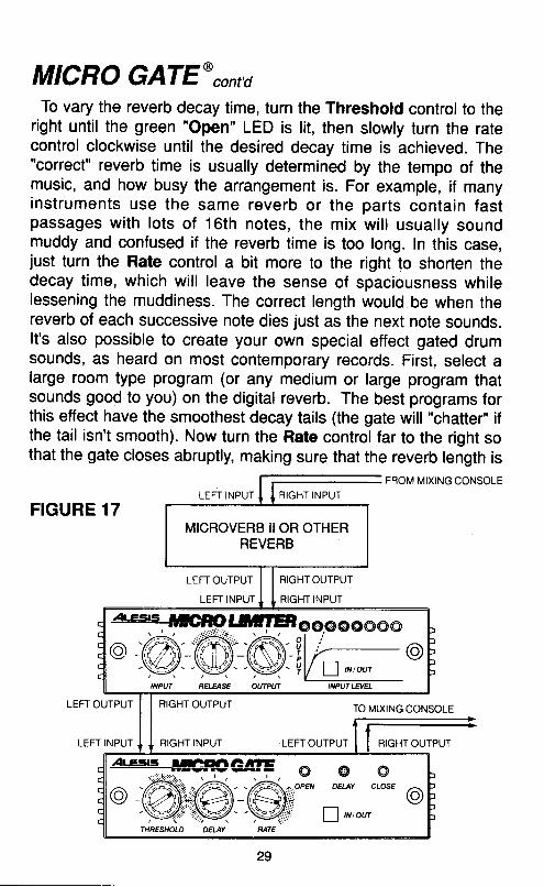
right until the green "Open" LED is lit, then slowly turn the ratecontrol clockwise until the desired decay time is achieved. The"correct" reverb time is usually determined by the tempo of themusic, and how busy the arrangement is. For example, if manyinstruments use the same reverb or the parts contain fastpassages with lots of 16th notes, the mix wil l usually soundmuddy and confused if the reverb time is too long. ln this case,just turn the Rate control a bit more to the right to shorten thedecay time, which wil l leave the sense of spaciousness whilelessening the muddiness. The correct length would be when thereverb of each successive note dies just as the next note sounds.It's also possible to create your own special effect gated drumsounds, as heard on most contemporary records. First, select alarge room type program (or any medium or large program thatsounds good to you) on the digital reverb. The best programs forthis effect have the smoothest decay tails (the gate will "chatter', ifthe tail isn't smooth). Now turn the Rate controlJar to the right sothat the gate closes abruptly, making sure that the reverb length is
FROM MIXING CONSOLELEFT INPUT T I RIGHT INPUT
FIGURE 17
LEFT OUTPUT
LEFT INPUT
RIGHT OUTPUT
RIGHT INPUT
TO MIXING CONSOLELEFT OUTPUT
LEFT INPUT
RIGHT OUTPUT
RIGHT INPUT LEFT OUTPUT RIGHT OUTPUT
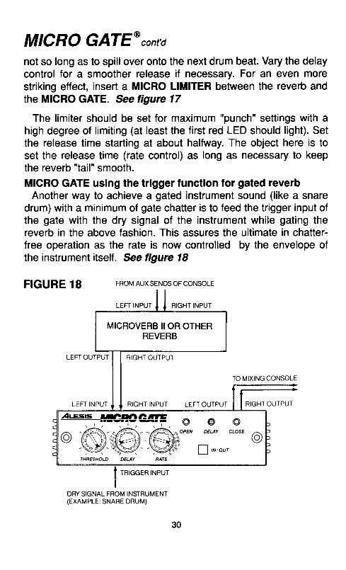
MICRO GATE'cont'dnot so long as to spill over onto the next drum beat. Vary the delaycontrol for a smoother release if necessary. For an even morestriking effect, insert a MICRO LIMITER between the reverb andthe MICRO GATE. See figure 17
The limiter should be set for maximum "punch" settings with ahigh degree of limiting (at least the first red LED should light). Setthe release time starting at about halfway. The object here is toset the release time (rate control) as long as necessary to keepthe reverb "tail" smooth.MICRO GATE using the trigger function for gated reverb
Another way to achieve a gated instrument sound (like a snaredrum) with a minimum of gate chatter is to feed the trigger input ofthe gate with the dry signal of the instrument while gating thereverb in the above fashion. This assures the ultimate in chatter-free operation as the rate is now controlled by the envelope ofthe instrument itself. See figure 18
FIGURE 18 FROM AUX SENDS OF CONSOLE
LEFT INPUT RIGHT INPUT
LEFT OUTPUT RIGHT OUTPUT
TO MIXING CONSOLE
LEFT INPUT RIGHT INPUT LEFT OUTPUT RIGHT OUTPUT
TRIGGER INPUT
DBY SIGNAL FROM INSTRUMENT(EXAMPLE: SNARE DRUM)
30
MICRO GATEtcontdMICRO GATE using the trigger function for special effects
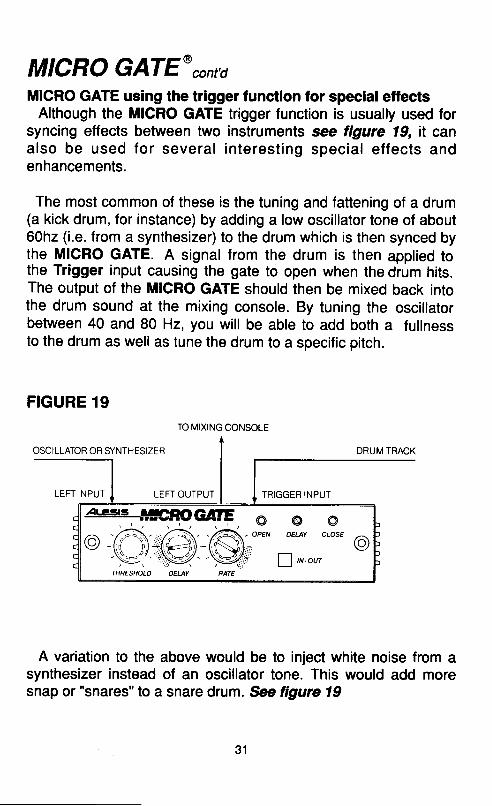
Although the MICRO GATE trigger function is usually used forsyncing etfects between two instruments see figure 19, it canalso be used for several interest ing special ef fects andenhancements.
The most common of these is the tuning and fattening of a drum(a kick drum, for instance) by adding a low oscillator tone of about60hz (i.e. from a synthesizer) to the drum which is then synced bythe MICRO GATE. A signal from the drum is then applied tothe Trigger input causing the gate to open when the drum hits.The output of the MICRO GATE should then be mixed back intothe drum sound at the mixing console. By tuning the oscillatorbetween 40 and 80 Hz, you will be able to add both a fullnessto the drum as well as tune the drum to a specific pitch.
FIGURE 19
OSCILLATOR OR SYNTHESIZER DRUM TRACK
LEFT INPUT LEFT OUTPUT TRIGGER INPUT
A variation to the above would be to inject white noise from asynthesizer instead of an oscillator tone. This would add moresnap or "snares" to a snare drum. *e figure 19
TO MIXING CONSOLE
31

MICRO EQ
DescriptionThe Alesis MICRO EQ is a mono 3 band semi-parametric
equalizer with sweepable frequencies and switchable bandwidthcontrols.
Equalization, or EQ, is the abil ity to control the harmonicbalance, or t imbre, of an instrument, and can be used tocompen$ate for frequency deficiencies in either microphones orsound equipment. There are three different types of equalizers, allof which you are probably familiar with.
The most common type of equalizer is the Shelving type. This isthe simple bass and/or treble control normally found on stereosystems, guitar amplifiers, etc. The term shelving refers to theamplitude plateau, or shelf, beginning at the turnover point(s) (100Hz and 10kHz in the diagram) and extending to the high (or low)end limit of the equalizer. The frequencies below (or above) theturnover point of the shelf are also atfected, but less and less sothe further away from the turnover point.
TurnoverFrequencles
FRONT
FOW€F
O tu^c oo.AtE:sls^991?gl|loN 1Qt ee15 *#EE$gV'€i,€!b"63n,H,"d*
LVO AIIgELEJ, UA. MAOE IN U S A SEfuICE 4FSqNEL
BACK
MICRO EQ cont'd
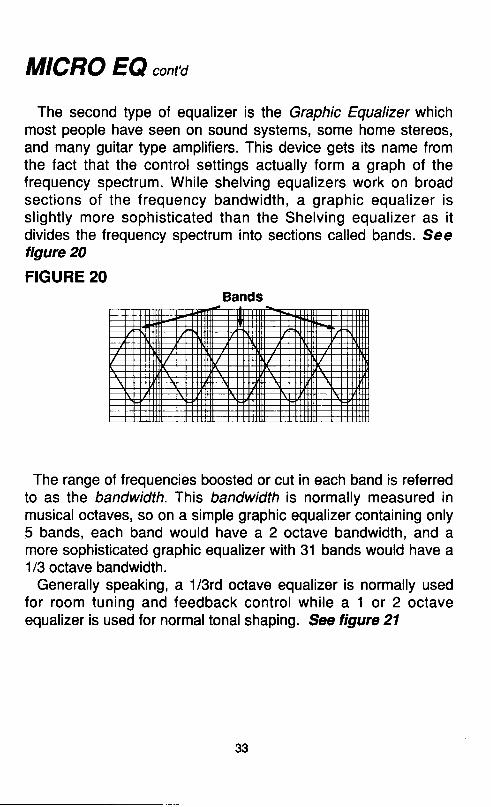
The second type of equalizer is the Graphic Equalizer whichmost people have seen on sound systems, some home stereos,and many guitar type amplifiers. This device gets its name fromthe fact that the control settings actually form a graph of thefrequency spectrum. While shelving equalizers work on broadsections of the frequency bandwidth, a graphic equalizer issl ight ly more sophist icated than the Shelv ing equal izer as i tdivides the frequency spectrum into sections called bands. Seefigure 20
FIGURE 20
The range of frequencies boosted or cut in each band is referredto as the bandwidth. This bandwidth is normally measured inmusical octaves, so on a simple graphic equalizer containing only5 bands, each band would have a 2 octave bandwidth, and amore sophisticated graphic equalizer with 31 bands would have a1/3 octave bandwidth.
Generally speaking, a 1l3rd octave equalizer is normally usedfor room tuning and feedback control while a 1 or 2 octaveequalizer is used for normal tonal shaping. See figure 21
Bands
33

MICRO EQ cont'd
FIGURE 21
2 Octave 1 Octave 1/3 Octave
By far the most versatile equalizer is the parametric type such asthe MlcRo EQ. While the graphic EQ always has a bandwidththat is fixed, the parametric allows for the bandwidth to be varied.This means that far fewer equalizer sections are required foreither tonal shaping or feedback suppression since the offendingfrequencies can be dialed in precisely. Although many parametricequalizers have a continuously variable bandwidth, it has beenfound that a switchable bandwidth from wide to narrow is not onlysutficient but far easier and faster to use. Hence, the MICRO EQis designed with a bandwidth control switchable lrom 2 octave(wide) to llzoctave (narrow), and thus is referred to as semi'parametric. See ligure 22FIGURE 22
2 Octave
34
1/2Octave
MICRO EQ cont'dControls
Frgq Select
Input Level
Freq Width
Low Freq Width High Freq Width
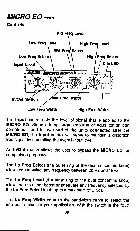
The lnput control sets the level of signal that is applied to theMICRO EQ. Since adding large amounts of equalization cansometimes lead to overload of the units connected after theMICRO EQ, the Input control will serve to maintain a distortionfree signal by controlling the overall input level.
An In/Out switch allows the user to bypass the MICRO Ee forcomparison purposes.
The Lo Freq Select (the outer ring of the dual concentric knob)alfows you to select any frequency between Z0 Hz and 1kHz.
The Lo Freq Level (the inner ring of the dual concentric knob)allows you to either boost or attenuate any frequency selected bythe Lo Freq Select knob up to a maximum of +15d8.
The Lo Freq Width controls the bandwidth curve to select theone best suited for your application. With the switch in the "out"
Mid Freq Level
MICRO EQ cont'dposition, the bandwidth is 2 octave while with the switch in thedepressed position, the bandwidth is ll2octave.
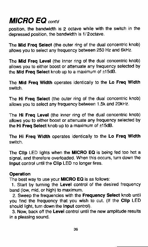
The Mid Freq Select (the outer ring of the dual concentric knob)allows you to select any frequency between 250 Hz and 6kHz.
The Mid Freq Level (the inner ring of the dual concentric knob)allows you to either boost or attenuate any frequency selected bythe Mid Freq Select knob up to a maximum of +15d8.
The Mid Freq Width operates identically to the Lo Freq Widthswitch.
The Hi Freq Select (the outer ring of the dual concentric knob)allows you to select any frequency between 1.5k and 20kHz.
The Hi Freq Level (the inner ring of the dual concentric knob)allows you to either boost or attenuate any frequency selected bythe Hi Freq Select knob up to a maximum of t15dB.
The Hi Freq Width operates identically to the Lo Freq Widthswitch.
The Clip LED lights when the MICRO EQ is being fed too hot asignal, and therefore overloaded. When this occurs, turn down theInput control until the Clip LED no longer fires.
OperationThe best way to use your MICRO EQ is as follows:1. Start by turning the Level control of the desired frequency
band (low, mid, or high)to maximum.2. Sweep the frequencies with the Frequency Select knob until
you find the frequency that you wish to cut. (lf the Clip LEDshould light, turn down the Input control).3. Now, back off the Level control untilthe new amplitude results
in a pleasing sound.
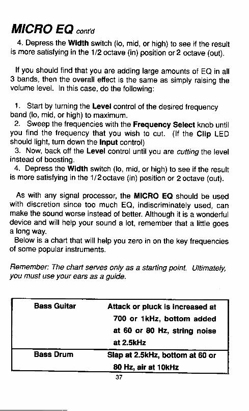
MICRO EQ cont'd4. Depress the Width switch (lo, mid, or high) to see if the result
is more satisfying in the l12octave (in) position or2 octave (out).
lf you should find that you are adding large amounts of Ee in all3 bands, then the overall effect is the same as simply raising thevolume level. In this case, do the following:
1. Start by turning the Level control of the desired frequencyband (lo, mid, or high)to maximum.2. Sweep the frequencies with the Frequency Select knob until
you find the frequency that you wish to cut. (lf the Clip LEDshould light, turn down the lnput control)
3. Now, back off the Level control until you are cutting the levelinstead of boosting.4. Depress the Width switch (lo, mid, or high) to see if the result
is more satisfying in the 1/2octave (in) position or 2 octave (out).
As with any signal processor, the MICRO Ee should be usedwith discretion since too much EQ, indiscriminately used, canmake the sound worse instead of better. Although it is a wonderfuldevice and will help your sound a lot, remember that a little goesa long way.
Below is a chart that will help you zero in on the key frequenciesof some popular instruments.
Remember: The chart serues only as a starting point. Ultimately,you must use your ears as a guide.
Bass Guitar
Bass Drum
Attack or pluck is increased at700 or 1kHz, bottom addedat 60 or 80 Hz, string noise
at 2.5kHz
Slap at 2.5kHz, bottom at 60 or80 Hz, air at 10kHz37
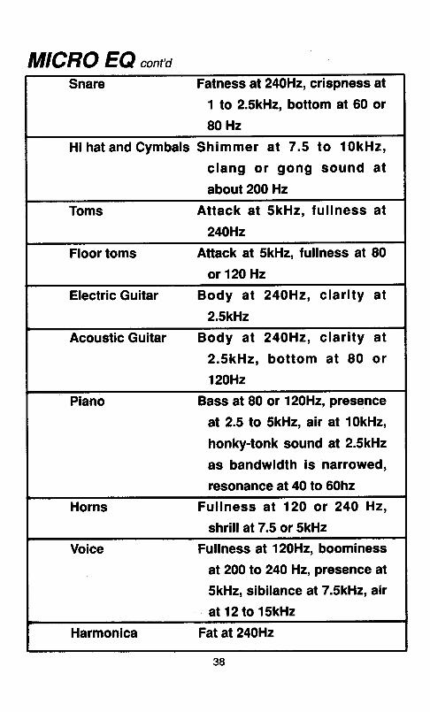
MICRO EQ cont'ctSnare Fatness at240Hz, crispness at
1 to 2.5kHz, bottom at 60 or80 Hz
Hi hat and CymbalsSh immer a t 7 .5 to 10kHz,
c lang or gong sound a t
about 200 Hz
Toms Attack at SkHz, fu l lness at
24OHz
Floor toms Attack at SkHz, fullness at 80
or 12OHz
Electric Guitar Body at 24OHz, clarity at
2.SkHz
Acoustic Guitar Body at
2.SkHz,
120H2
240H2, clarity at
bottom at 80 or
Piano Bass at 80 or 12OHz, presence
at 2.5 to SkHz, air at 10kHz,
honky-tonk sound at 2.5kHz
as bandwidth is narrowed,
resonance at 40 to 60hz
Horns Fuf lness at 120 or 240 Hz,
shrill at 7.5 or SkHz
Voice Fuflness at 12OHz, boominess
at 200 to 24O Hz, presence at
SkHz, sibilance at 7.5kHz, air
at12 to 15kHz
Harmonica Fat at 24OHz
38
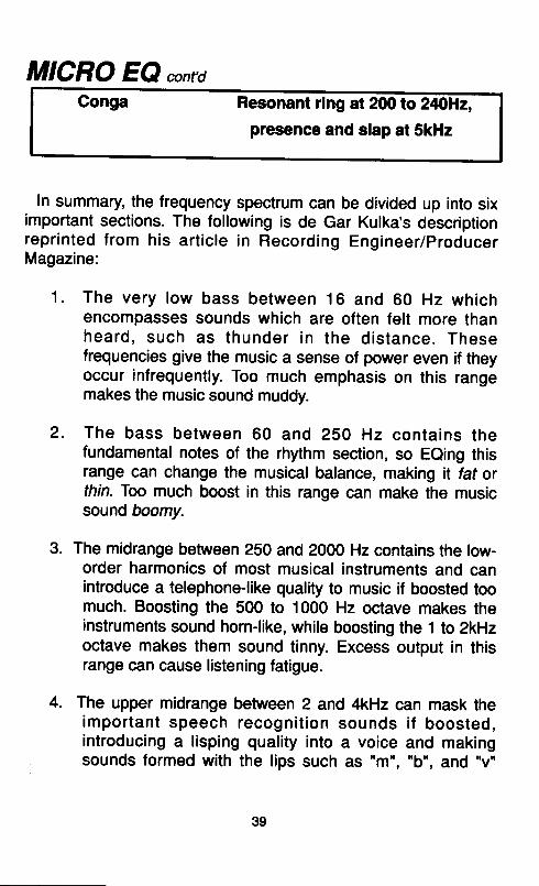
MICRO EQ cont'dConga Resonant ring at 200 to 240lHz,
presence and slap at 5kHz
In summary, the frequency spectrum can be divided up into siximportant sections. The following is de Gar Kulka's descriptionrepr inted from his art ic le in Recording Engineer/producerMagazine:
1. The very low bass between 16 and 60 Hz whichencompasses sounds which are often felt more thanheard , such as thunder in the d is tance. Thesefrequencies give the music a sense of power even if theyoccur infrequently. Too much emphasis on this rangemakes the music sound muddy.
2. The bass between 60 and 2SO Hz contains thefundamental notes of the rhythm section, so Eeing thisrange can change the musical balance, making it fat orthin. Too much boost in this range can make the musicsound boomy.
3. The midrange between 250 and 2000 Hz contains the low-order harmonics of most musical instruments and canintroduce a telephone-like quality to music if boosted toomuch. Boosting the 500 to 1000 Hz octave makes theinstruments sound horn-like, while boosting the 1 to 2kHzoctave makes them sound tinny. Excess output in thisrange can cause listening fatigue.
4. The upper midrange between 2 and 4kHz can mask theimportant speech recogni t ion sounds i f boosted,introducing a l isping quality into a voice and makingsounds formed with the lips such as "m", "b", and "v"
39
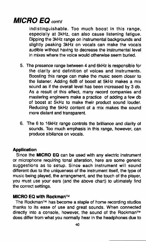
MICRO EQ ant'di nd is t ingu ishab le . Too much boos t in th is range,especially at 3kHz, can also cause listening fatigue.Dipping the 3kHz range on instrumental backgrounds andslightly peaking 3kHz on vocals can make the vocalsaudible without having to decrease the instrumental levelin mixes where the voice would otherwise seem buried.
The presence range between 4 and 6kHz is responsible forthe clarity and definit ion of voices and instruments.Boosting this range can make the music seem closer tothe listener. Adding 6dB of boost at SkHz makes a mixsound as if the overall level has been increased by 3 db.As a result of this effect, many record companies andmastering engineers make a practice of adding a few dbof boost at SkHz to make their product sound louder.Reducing the SkHz content of a mix makes the soundmore distant and transparent.
The 6 to 16kHz range controls the brilliance and clarity otsounds. Too much emphasis in this range, however, canproduce sibilance on vocals.
ApplicationSince the MICRO EQ can be used with any electric instrument
or microphone requiring tonal alteration, here are some genericsuggest ions as to setup. Since each instrument wi l l sounddifferent due to the uniqueness of the instrument itself, the type ofmusic being played, the arrangement, and the touch of the player,you must use your ears (and the above chart) to ultimately findthe correct settings.
MICRO EQ with RockmanruThe Rockmanru has become a staple of home recording studios
thanks to its ease of use and great sounds. When connecteddirectly into a console, however, the sound of the Rockmanrudoes differ from what you normally hear in the headphones due to
40
5.
6.
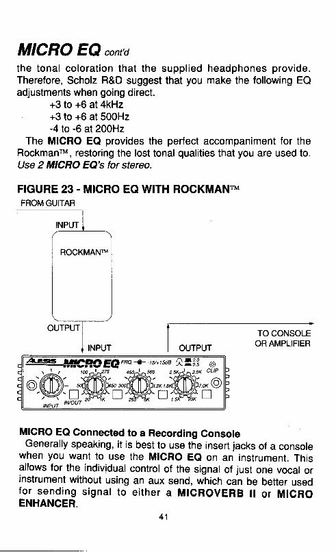
MICRO EQ cont'dthe tonal colorat ion that the suppl ied headphones provide.Therefore, Scholz R&D suggest that you make the following EQadjustments when going direct.
+3 to +6 at 4kHz+3 to +6 at 500H2-4 to -6 at 200H2
The MICRO EQ provides the perfect accompaniment for theRockmanrM, restoring the lost tonal qualities that you are used to.Use 2 MICRO EQb tor stereo.
FIGURE 23 - MICRO EO WITH ROCKMANTMFROM GUITAR
MICRO EQ Gonnected to a Recording ConsoleGenerally speaking, it is best to use the insert jacks of a console
when you want to use the MlcRo Ee on an instrument. Thisallows for the individual control of the signal of just one vocal orinstrument without using an aux send, which can be better usedfor send ing s igna l to e i ther a MrcRovERB l l o r MlcRoENHANCER.
4 1
ROCKMANTM
AtEts.s lyHl}GllDriaFRa +-lsnrsda |lrolu O
'@;*@rffiH@'hl5
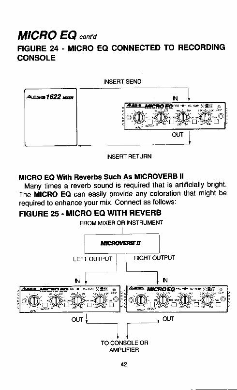
MICRO EQ cont'dFIGURE 24 - MICRO EO CONNECTED TO RECORDINGCONSOLE
atersl622 m
INSERT SEND--l
IN T
INSERT RETURN
MICRO EQ With Reverbs Such As MIGROVERB llMany times a reverb sound is required that is artificially bright.
The MICRO EQ can easily provide any coloration that might berequired to enhance your mix. Connect as follows:
FIGURE 25 . MICRO EQ WITH REVERB
our l low---lf-TO CONSOLE OR
AMPLIFIER
42
FROM MIXER OR INSTRUMENT
rrh4rrEDeol?
@
T-lo
Es |IACqOEA rao -t-.w,rue ll,oou.
'@;=-@='W-,@
MICRO EQ contd
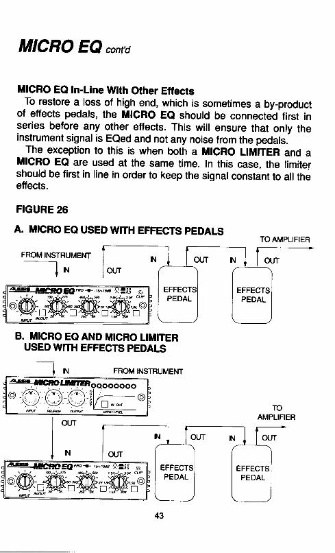
MICRO EQ In-Line With Other EffectsTo restore a loss of high end, which is sometimes a by-product
of effects pedals, the MlcRo Ee should be connected first inseries before any other etfects. This will ensure that only theinstrument signal is EQed and not any noise from the pedals.
The exception to this is when both a MlcRo LlMlrER and aMlcRo EQ are used at the same time. In this case, the limitershould be first in line in order to keep the signal constant to all theetfects.
FIGURE 26
A. MICRO EO USED WITH EFFECTS PEDALS
FROM INSTRUMENT- l ^
B. MICRO EQ AND MICRO LIMITERUSED WTH EFFECTS PEDALS
t N FROM INSTRUMENT
TOAMPLIFIER
TO AMPLIFIER
EFFECTPEDAL
EFFECTSPEDAL
PEDALEFFECTS
PEDAL
MICRO ENHANCER'
a)r ' ' v ( ) ( )(r ryrc
\-/ \__/^LSS|S aarooaD.rtu El=!c3
LoSANGELES, cA. -
i loeuu s e
R IiFI't L
{ t { l\_-/ \_-/
rcEIS@CffiEWEFSSmTTOUEO
$rcEffiI
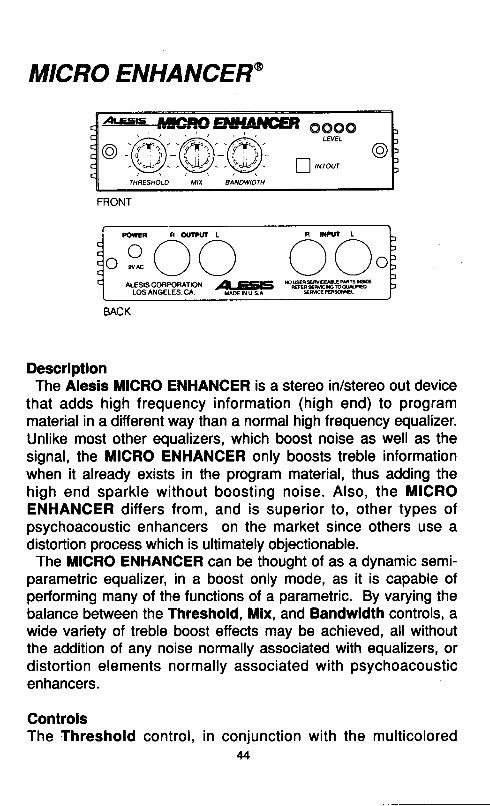
DescriptionThe Alesis MICRO ENHANCER is a stereo in/stereo out device
that adds high frequency information (high end) to programmaterial in a different way than a normal high frequency equalizer.Unlike most other equalizers, which boost noise as well as thesignal, the MlcRo ENHANCER only boosts treble informationwhen it already exists in the program material, thus adding thehigh end sparkle wi thout boost ing noise. Also, the MICROENHANCER differs from, and is superior to, other types ofpsychoacoustic enhancers on the market since others use adistortion process which is ultimately objectionable.
The MIGRO ENHANGER can be thought of as a dynamic semi-parametric equalizer, in a boost only mode, as it is capable ofperforming many of the functions of a parametric. By varying thebalance between the Threshold, Mix, and Bandwidth controls, awide variety of treble boost etfects may be achieved, all withoutthe addition of any noise normally associated with equalizers, ordistortion elements normally associated with psychoacousticenhancers.
ControlsThe Threshold control, in conjunction with the multicolored
44
FRONT
BACK
MICRO ENHANCER@,O't,ALED s, determines the slope, or the way the MICRO ENHANCERwillwork on high and mid frequencies.
The Mix control determines how much high frequency informationis added to the signal going through the unit.
The Bandwidth control determines how much treble or mid-rangeis added to the s igna l . Wi th the Bandwid th cont ro lcounterclockwise (all the way to the left), only the very highfrequencies are added; with the Bandwidth control at maximum(all the way to the right) upper and lower midrange frequenciesare added as well.
An In /Out sw i tch a l lows the user to bypass the MICROENHANCER for comparison purposes, if so desired.
OperationAfter connecting your MICRO ENHANCER (refer to the section
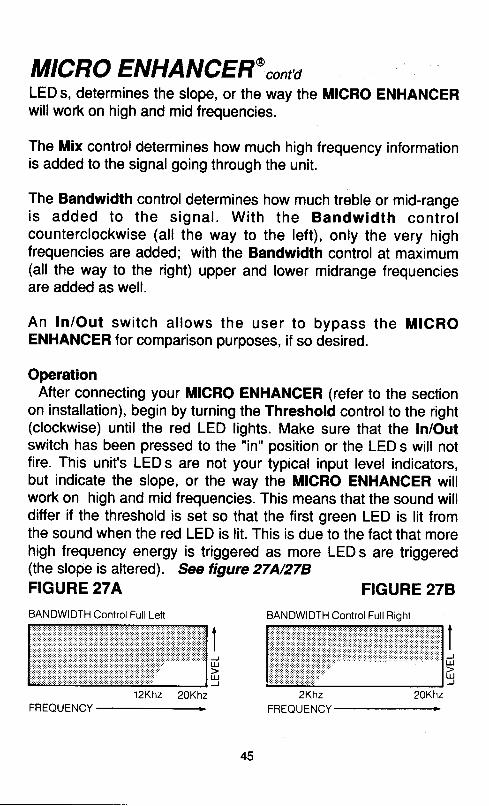
on installation), begin by turning the Threshold control to the right(clockwise) until the red LED lights. Make sure that the In/Outswitch has been pressed to the "in" position or the LED s will notfire. This unit's LED s are not your typical input level indicators,but indicate the slope, or the way the MICRO ENHANCER willwork on high and mid frequencies. This means that the sound willdiffer if the threshold is set so that the first green LED is lit fromthe sound when the red LED is lit. This is due to the fact that morehigh frequency energy is triggered as more LED s are triggered(the slope is altered). See tigure 27N278FIGURE 27A FIGURE 278
I)uJuJ
ItrE
BANDWIDTH Control Full Left BANDWIDTH Control Ful l Rioht
FREQUENCY
45
MICRO ENHANCER@"o,t'aNow begin to turn the Mix control to the right (clockwise) until
the desired amount of high frequency boost is achieved. You canthink of the Mix control as an amount control, as this is the onethat will add the amount of high frequency boost desired to thesignal (or signals) that you send to the MICRO ENHANCER .
Now turn the Bandwidth control until the desired balance ofhighs and midrange is achieved. Start with this control all the wayto the right (clockwise) or at full bandwidth, and adjust it until theinstrument or microphone reaches the point of greatest clarity.Be careful to avoid adding excessive midrange which will makean instrument OR vocal sound harsh. See the next section formore specific applications.
In order to compare the enhanced sound to the original sound,depress the ln/Out button.
You should experiment with different settings of the Thresholdcontrol and LED indicators as the sound will vary dramaticallybetween various settings of the Threshold, Mix, and Bandwidthcontrols. Also, don't be afraid to drive the unit hard so as to keepthe red LED on a l l the t ime as th is i s when the MICROENHANCER is operating at its maximum.
ApplicationThe MICRO ENHANCER is an extremely versatile device and
may be used in a variety of applications. During recording orplaying live, the MICRO ENHANCER can be used as the ultimate,and quietest treble booster on guitars, keyboards, and vocal andinstrument mics.
Here are just a few possibil i t ies and helpful hints. Pleaseremember that the control settings will vary depending upon theactual equipment used, the style of music being played, and theparticular playing style of the musician. The settings are nominally'correct however, and should serve as a reasonably good startingpoint.
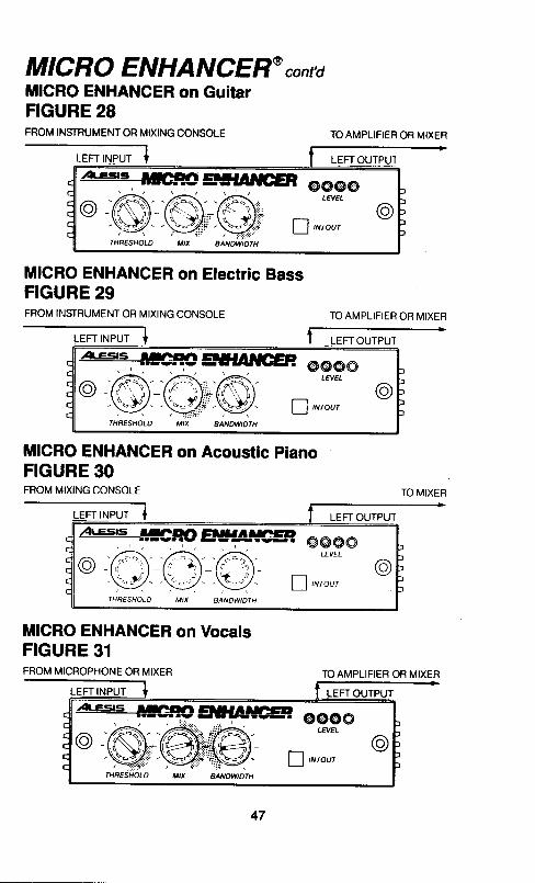
MICRO ENHANCER@ cont'dMICRO ENHANCER on GuitarFIGURE 28FROM INSTRUMENT OR MIXING CONSOLE
MICRO ENHANCER on Electric BassFIGURE 29FROM II.ISTRUMENT OR MIXING CONSOLE
MICRO ENHANCER on Acoustic PianoFIGURE 30FROM MIXING CONSOLE
MICRO ENHANCER on VocalsFIGURE 31FROM MICROPHONE OR MIXER
TOAMPLIFIEF OR MIXER
TO AMPLIFIEB OR MIXER
TO MIXER
TO AMPLIFIER OR MIXER
47
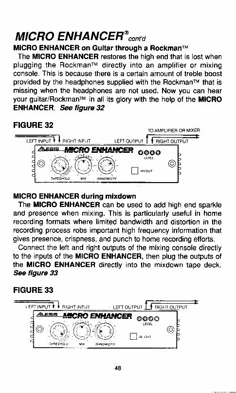
MICRO ENHANCER',onraMICRO ENHANCER on Guitar through a RockmanrMThe MICRO ENHANCER restores the high end that is lost when
plugging the RockmanrM direct ly into an ampl i f ier or mixingconsole. This is because there is a certain amount of treble boostprovided by the headphones supplied with the RockmanrM that ismissing when the headphones are not used. Now you can hearyour guitar/RockmanrM in all its glory with the help of the MICROENHANCER. See figure 32
FIGURE 32 ToAMPLTFTER oR MrxER
LEFT INPUT I I RIGHT INPUT LEFTOUTPUT I I RIGHTOUTPUT
MICRO ENHANCER during mixdownThe MICRO ENHANCER can be used to add high end sparkle
and presence when mixing. This is particularly useful in homerecording formats where limited bandwidth and distortion in therecording process robs important high frequency information thatgives presence, crispness, and punch to home recording efforts.
Connect the left and right outputs of the mixing console directlyto the inputs of the MICRO ENHANCER, then plug the outputs ofthe MICRO ENHANCER directly into the mixdown tape deck.*e figure 33
FIGURE 33
48
MICRO CUE AMP
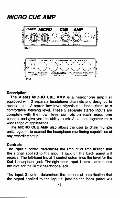
DescriptionThe Alesis MIGRO CUE AMP is a headphone ampl i f ier
equipped with 2 separate headphone channels and designed toaccept up to 2 stereo low level signals and boost them to acomfortable listening level. These 2 separate stereo inputs arecomplete wi th their own level controls on each headphonechannel and give you the ability to mix 2 sources together for awide range of applications.
The MIGRO CUE AMP also allows the user to chain multipleunits together to expand the headphone monitoring capabilities ofany recording setup.
GontrolsThe Input 1 control determines the amount of amplification thatthe signal applied to the input 1 jack on the back panel wil lreceive. The left-hand Input 1 control determines the level for theOut t headphone jack. The right-hand Input 1 control determinesthe levelfor the Out 2 headphone jack.
The Input 2 control determines the amount of amplification thatthe signal applied to the input 2 jack on the back panel will
49
FRONT
R INPUT1 L STEREOUNEOUT F I}IPUT2 Lo,eooooo.o\lss:91?9l{loN 1Qr eq15 *#*13'.8vl3'^f'.'""63f,H36"'�
LVO AI \UELE>, UA MADE IN U S A SEAVCT OIFSO\TI .
MICRO CUE AMP cont'dreceive. The left-hand Input 2 control determines the level for theOut t headphone jack.The right-hand tnput 2 control determines the level for the Out 2headphone jack.
The MICRO CUE AMP features 2 separate headphone outputjacks, each with independent level control over inputs 1 and 2.Out 1 is a stereo headphone output with the volume controlled bythe left Input 1 and Input 2 controls.Out 2 is a stereo headphone output with the volume controlled bythe right Input 1 and Input 2 controls.
The green LED indicates that the unit is on.
The Input 1 Jacks on the back panel are a stereo iack which canbe used for connection to the stereo auxil iary sends of a mixingconsole, or used as an input for an instrument such as guitar orkeyboard for private practicing.
The lnput 2 Jacks on the back panel are a stereo jack which canbe used for connection to the stereo auxiliary sends of a mixingconsole, or used as an input for an instrument such as guitar orkeyboard for pr ivate pract ic ing. The Input 2 Jack is alsoparalleled with the Stereo Line Out Jack for chaining additionalMICRO CUE AMPS together.
Stereo Line Out is used for chaining additional MICRO CUEAMP units together. Only the signal applied to Input 2 isavailable at the Stereo Line Out.
OperationAfter connecting your MICRO CUE AMP (refer to the section on
installation), simply insert your headphones into either Out 1 orOut 2 on the front panel, and turn the Input 1 and/or Input 2control until the desired headphone volume is reached. MICROCUE AMP will adequately drive any set of headphones, either low(8 ohms) or high (600 ohms) impedance.
50
MICRO CUE AMP contd
Please Note: lf you are connecting just one source to yourMrcnO CUE AMP, make sure that the unused input control isturned counterclockwise (to the left, or off). This wiil prevent anyunwanted, stray noises from being heard.
ApplicationThe Alesis MICRO CUE AMP is a convenient and inexpensive
time saver, suitable for numerous applications. This litile box willcome in handy wherever an extra set of headphones is need, sodon't limit yourself only to these examples.
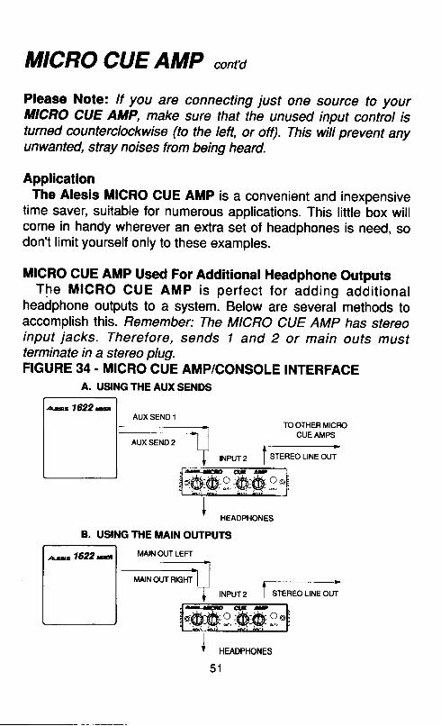
MICRO CUE AMP Used For Additional Headphone OutputsThe MICRO CUE AMP is perfect for adding addi t ional
headphone outputs to a system. Below are several methods toaccomplish this. Femember: The MICRO CUE AMp has stereoinput jacks. Therefore, sends I and 2 or main outs mustterminate in a stereo plug.FIGURE 34 - MICRO CUE AMP/CONSOLE INTERFACE
A. USINGTHEAUXSENDS
TO OTHER MICROCUEAMPS
o F * O
Iv neaopHoues
B. USING THE MAIN OUTPUTS
MAIN OUT LEFT
HEADPHONES
5 1
AUX SEND 1
STEREO LINE OUT
g,@@g

MICRO CUE AMP cont'dGhaining MICRO CUE AMPS TogetherSeveral MICRO CUE AMPS may be connected together in order
to add an unlimited number of headphone outputs to a system.Remember: The Stereo Line Out jack is paralleled with lnput2, so lnput 2 must always be used as the main input whenbeing used in this application.
FIGURE 35. CHAINING MICRO CUE AMPS
STEREO LINE OUTFROM MIXING CONSOLE-t
INPUT 2
/ \ TOOTHER M|CRO/ \ cUEAMPS-7-t \ t-----.---.-----*'
I | N P U T 2 . l
.48 lrccxD G aE
@@9.@e9"I ,roor*o*r,
MICRO CUE AMP Used For Quiet Pract ic ing With AnInstrument
MICRO CUE AMP makes the perfect private rehearsal monitorsystem. Simply connect as shown on the next page, turn up thevolume, and go for it!
HEADPHONES
52
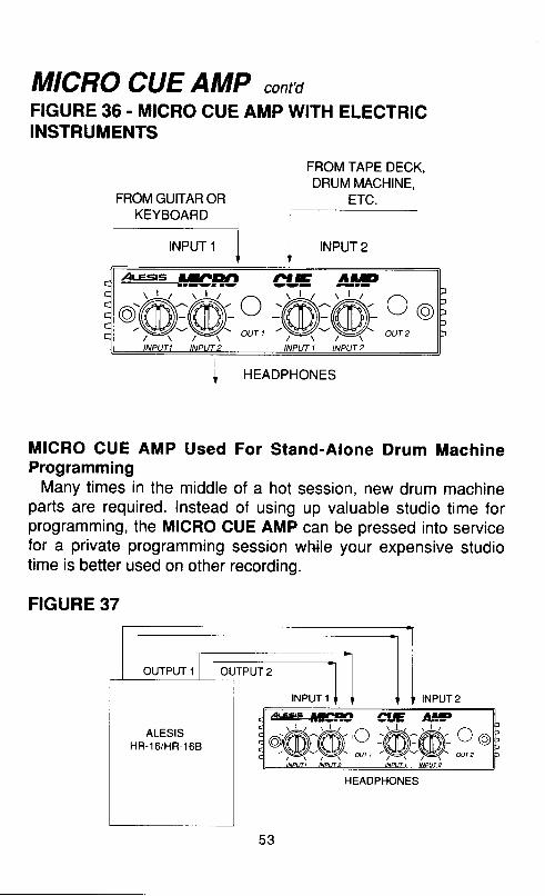
MICRO CUE AMP cont'dFIGURE 36. MICRO CUE AMP WITH ELECTRICINSTRUMENTS
FROM GUITAR ORKEYBOARD
FROM TAPE DECK,DRUM MACHINE,
ETC.
rNPUr 1 I INPUT 2
HEADPHONES
MICRO CUE AMP Used For Stand-Alone Drum MachineProgramming
Many times in the middle of a hot session, new drum machineparts are required. lnstead of using up valuable studio time forprogramming, the MICRO CUE AMP can be pressed into servicefor a private programming session while your expensive studiotime is better used on other recording.
FIGURE 37
At.Cs.s lu!c'?fD
t@@.:M, AE-ffiffii oq-p-p- ourz
ALESISHR-16/HR.168
,a'.gs |!c!r!
'@@.9,dE AE-A^A--v:w \ / / a
OUT 2
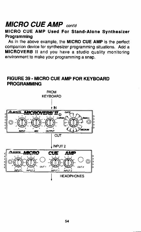
MICRO CUE AMP cont'dMICRO CUE AMP Used For S tand-A lone Synthes izerProgramming
As in the above example, the MICRO CUE AMP is the perfectcompanion device for synthesizer programming situations. Add aMICROVERB l l and you have a s tud io qua l i t y mon i to r ingenvironment to make your programming a snap.
FIGURE 39. MICRO CUE AMP FOR KEYBOARDPROGRAMMING
FROMKEYBOARD
Il n r
HEADPHONES
At.Ets FllrCHDArcltaDEgt on*-. --..
",@.@-@%o)ru/ \ / \ / \ . 6 _ r l
ot@
54
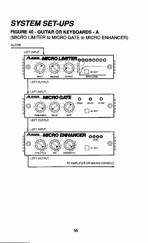
SYSTEM SET-UPSFIGURE 40 - GUITAR OR KEYBOARDS. A(MICRO LIMITER to MICRO GATE to MICRO ENHANCER)GUITAR
55
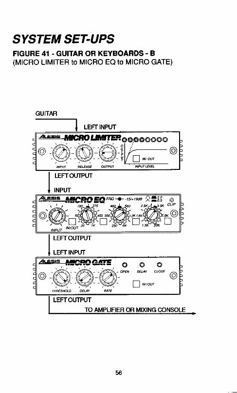
SYSTEM SET.UPSFIGURE 41 . GUITAR OR KEYBOARDS - B(MICRO LIMITER to MICRO EQ to MICRO GATE)
GUITAR
56
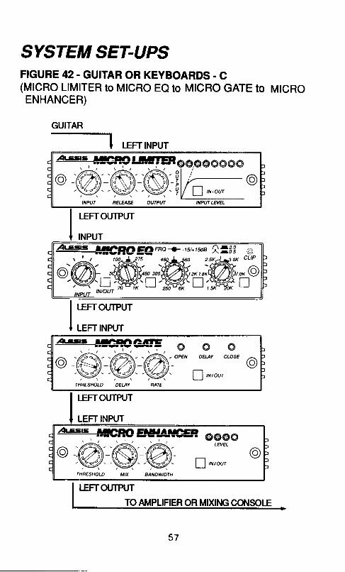
SYSTEM SET-UPSFIGURE 42. GUITAR OR KEYBOARDS. C(MlcRo LIM|TER to MTCRO EQ ro MTCRO GATE to MtcRoENHANCER)
LEFT INPUT
LEFTOTJTPUTTO AMPLIFIER OR MIXING COT,ISOLE
57
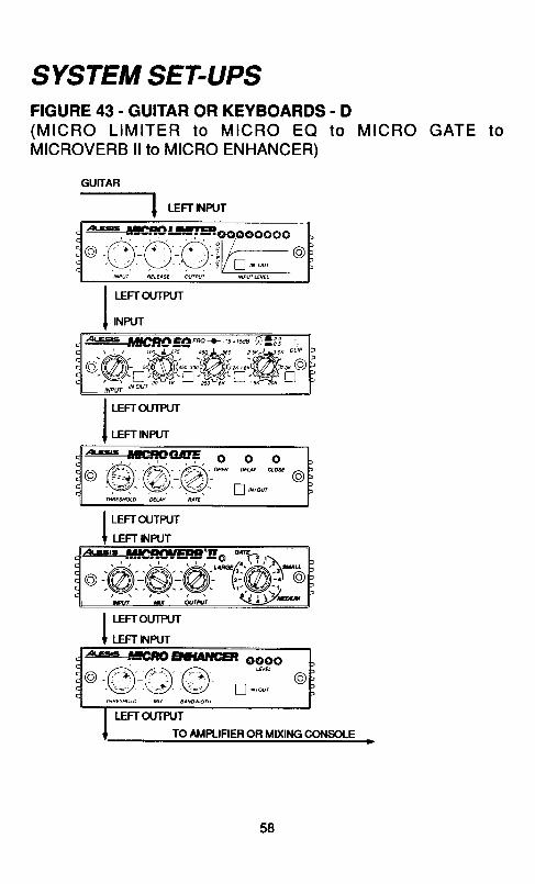
SYSTEM SET-UPSFIGURE 43 . GUITAR OR KEYBOARDS. D( M I C R O L I M I T E R t o M I C R O E Q t o M I C R O G A T EMICROVERB llto MICRO ENHANCER)
GUTTAR-tLEFTNPUT
o f ' ) ' - f ' ) - f ' ) ! l , - - -@.\__/ \/ \J ,tV a ^ *,INPIT AELEISE OU|PUI
I r-errotnrur
I rrururMts F!E|C3ID ClAr Frc -J.15.1tu8 A=,oi
'@;*-@='ffinW;'I Lerrorrnn
I urrrurur
I lerrourrur
I LEFT NPUT
o
o o o. MN usr aos
l\- v' ! , , ,o'
a R€;l-CaA:A:\g_,y4_.y4
I urrourrur
T LEFT I.IPUT
58
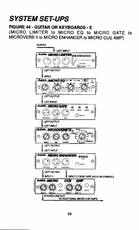
SYSTEM SET.UPSFIGURE 44. GUITAR OR KEYBOARDS. E( M I C R O L I M I T E R t o M T C R O E Q t o M T C R O G A T E t oMICROVERB ll to MICRO ENHANCER to MTCRO CUE AMp)
GUTlrAR-1
' LEFT INRJT
oooooo
I |€Frcurpur
[ * r *
E:{}!�G4o€tll.aFB oooo
[,"r-r r*rntopE oEcK oR cor{solE
J LEFrqnpur
I LEFT NRJT
I LEFrourpur
I r-err rrunrr
I r-erra,rrnrrI r.lRJTl
59
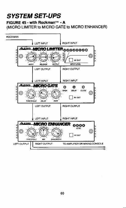
SYSTEM SET-UPSFIGURE 45 - with RockmanrM - A(MICRO LIMITER to MICRO GATE to MICRO ENHANCER)
ROCKMAN
RIGHT INPUT
,'�t€s's I;GBO !.s!!EP g@..@@@@@O
f1 ,r,ourINPUTIEIEL
LEFT OUTPUT
LEFT INPUT
RIGHT OUTPUT
RIGHT INPUT
A€S'=;ICFOG4trE O @ O
o z6,_zA,_-A,_; ;, ',i" t'- .W---W--NZ- v,*ou,LEFT OUTPUT
LEFT INPUT
RIGHT OUTPUT
RIGHT INPUT
,aLEsrs ;;eFO EfllaffG=P @@@oLFITELo @
V,r ,ou,
OUTPUT RIGHT OUTPUT TO AMPLIFIER OR MIXING CONSOLE
60
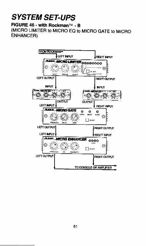
SYSTEM SET-UPSFIGURE 46 - with Rockmanru - B(MICRO LIMITER to MTCRO Ee to MTCRO GATE to MTCROENHANCER)
a :&xf. n.h d t . - " '
61
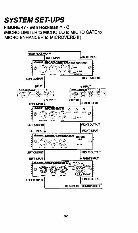
SYSTEM SET.UPSFIGURE 47 - with RockmanrM - C(MICRO LIMITER to MICRO EQ to MICRO GATE toMICRO ENHANCER to MICROVERB ll)
RIGHTOUIPUT
reHTFPUT
THTOUIPI'T
62
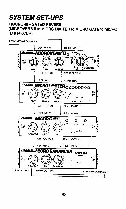
SYSTEM SET.UPSFIGURE 48. GATED REVERB(MICROVERB ll to MICRO LIMITER to MTCRO GATE to MTCROENHANCER)
FROM MIXING CONSOTE
LEFT INPUT RIGHT INPUT
LEFT OUTPUT
LEFT INPUT
RIGHT OUTPUT
RIGHT INPUT
LEFT OUTPUT
LEFT INPUT
RIGHT OUTPUT
RIGHT INPUT
a'E== ;llGgoclE o oo A-.A:i6;" ;'t=t
'n ' ou'THRES/./oI-D DELAY RAIE
@"t*t
o
LEFT OUTPUT
LEFT INPUT
RIGHT OUTPUT
RIGHT INPUT
,zx-Esrs lleFOEf;|afGEF @@@@LANEL
@V , n t o w
LEFT OUTPUT RIGHT OUTPUT TO MIXING CONSOLE
63
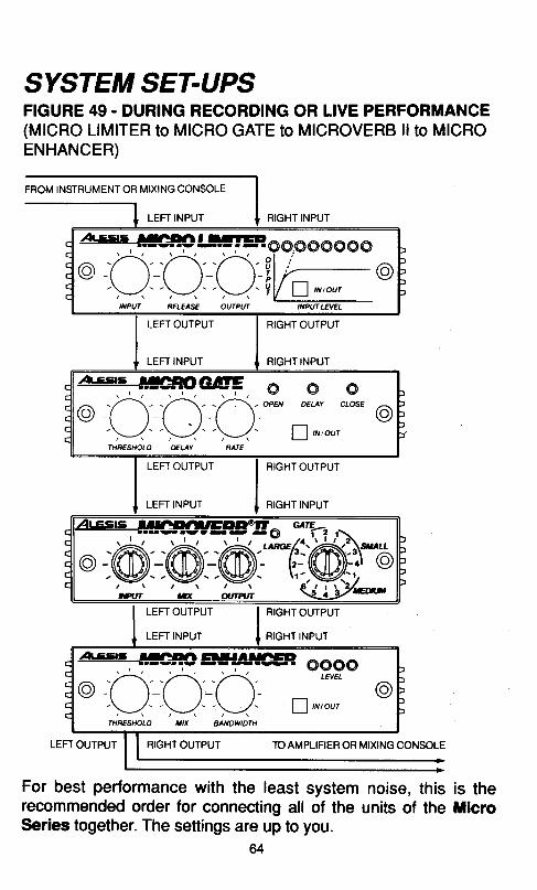
FIGURE 49. DURING RECORDING OR LIVE PERFORMANCE(MICRO LIMITER to MICRO GATE to MICROVERB llto MICROENHANCER)
FROM INSTRUMENT OR MIXING CONSOLE
LEFT INPUT RIGHT INPUT
A€s=#eBO lJlllEP 6 @.@ @ @ @ @ @
INPUT NELEASE OUTPIIf INPU| LA/EL
LEFT OUTPUT
LEFT INPUT
RIGHT OUTPUT
RIGHT INPUT
A-es|s +lcPoctr, @e-(t-(t-o.;-\-1"\7'-\-1'
,t9,
f1 ,*,our
ocl.osE
/Av
LEFT OUTPUT
LEFT INPUT
RIGHT OUTPUT
RIGHT INPUT
SYSTEM SET-UPS
LEFT OUTPUT
LEFT INPUT
RIGHT OUTPUT
RIGHT INPUT
RIGHT OUTPUT TO AMPLIFIER OR MIXING CONSOLE
For best performance with the least system noise, thisrecommended order for connecting all of the units of theSeries together. The settings are up to you.
is thellicro
SPECIFICATIONS
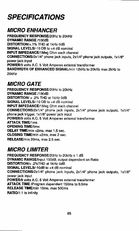
MICRO ENHANCERFREOUENCY RESPONS92OHz to 20kHzDYNAMIC RANGE/1OOdBDISTORTION/<.1% THD at lkHz OdBSIGNAL LEVELS/-10 DB to +4 dB nominalINPUT IMPEDANCE/IMeg Ohm each channelCONNECTIONS/2x114" phone jack inputs, 2x114" phone jack outputs, 1x1/8"power jack inputPOWER/9 volts A.C. 5 Volt Amperes externallransformerBANDWIDTH OF ENHANCED SlGNAUmin l2kHzto 20kHz max 2kHz to20kHz
MICRO GATEFREOUENCY RESPONSE/2OHz to 2OKHzDYNAMIC RANGE/1OOdBilSTORnONt <.zYo THD at lkHz OdBSIGNAL LEVELS/-10 DB to +4 dB nominalINPUT IMPEDANC9IMeg Ohm each channelCONNECflONS/2x114' phone jack inputs, 2x1t4- phone jack outputs, 1x1/4"phone jack trigger, 1x1/8" power jack inputPOWER/9 volts A.C. 5 Volt Amperes external transformerATTACKTIM9ImsOPENING TIME/SmsDELAY TIME/min <2ms, max 1.5 sec.CLOSING TIME/min <2ms, max 2 sec.RELEASEmin 20ms, max 2.5 sec.
MICRO LIMITERFREOUENCY RESPONSS20Hz ro 2okHzr 1 dBDYNAMIC RANGUlnput 100d8, output dependent on RatioDfSTORnONk.2Y"THD at lkHz OdBSIGNAL LEVELS/-10d8 to +4 dB nominalCONNECflONS/2x1|4" phone jack inputs, 2xll4 phone jack outputs, 1x1/8"power jack inputPOWER/9 vohs A.C.5 Volt Amperes external translormerATTACK TIME /Program dependent 150ms to 0.5msRELEASE TlMBmin 10ms, max 500msRATIO/I:1 to infinity
65
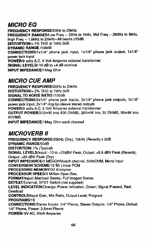
MICRO EQFREOUENCY RESPONSE/20H2 to ZokHzFREOUENCY RANGESTLow Freq -- ZoHz to 1kHz, Mkl Freq - 25OHz to 6kHz'High Freq - 1.5kHz to 2OkHz-All bands t15dBDfSTORTIONI<.1"/"THD at lkHz OdBDYNAMIC RANGE/1OOdBCONNECTIONS/Ix1/4' phone iack input, lxll4 phone jack oulput, 'lx'l18
power iack inputPOWER/9 volts A.C. 5 Volt Amperes externaltransformerSIGNAL LEVELSF10 dB to +4 dB nominalINPUT IMPEDANCFJI Meg Ohm
MICRO CUE AMPFREOUENCY RESPONS92OHz to 2okHzDfSTORTION/<.2Y"THD at lkHz 0dBSIGNAL TO NOISE RATIO /1OOdBCONNECflONS/2x114" phone jack inputs, 2x1/4'phone iack oulputs, 1x1l8"power jack inpul,2x114' ring-tip-sleeve slereo outputsPOWER/9 vohs A.C. 5 Volt Amperes exlernal transformeroUTPUT POWER/s1omW into 600 oHMS, 260mW into 30 oHMS, 95mW intosOHMSINPUT IMPEDANCE/1Meg Ohm each channel
MICROVERB IIFREOUENCY RESPONSE/2OkHz (Dry), 15kHz (Reverb) i 2dBDYNAMIC RANGE/9OdBDl STORTION t . 1 % (Ty picallSIGNAL LEVELS/lnput: -10 to +20dBV Peak, Output: +8.5 dBV Peak (Reverb),Output: +20 dBV Peak (Dry)INPUT IMPEDANC9I MEGOHMeach channel, 500kOHM, Mono lnputCONVERSION SCHEMBI6 Bit Linear PCMPROCESSING MEMORYR2 KibbytesPROCESSOR SPEED/3 Million Oper./Sec.FORMAT/lnput: Matrixed Stereo, Full lmaged StereoDEFEAT/External, SPST Switch (not supplied)LEVEL INUCAnON/Orange: Power indication, Green: Signal Present, Red:OverloadCONTROLS/lnpul Gain, Mix Ratio, Oulpul Level, ProgramPROGRAMS/16CONNECnONS/Stereo lnputs: 1 /4' Phone, Stereo Outpuls: 1/4' Phone, Defeal:1/4" Phone, Power:3.5mm PhonePOWEF/ 9V AC, SVoh-Amperes
66
ALES'S LI MITED WARRANTY
ALEsls OORPORATION CALESIS') wanants this p.oduct to b€ fr€€ ot d€tec'ts in matefiat andwofimanship for a period ol 90 days lrom the dats ot original retail purchase. rnis wananty ii enrorceaureonly by the ofuinal retail purciasor.
. . . Io b€ Protected by th:is wananty, the puichaser must.complete and r€tum the endos€d wanantycard within 14 days of purchase.
. . During ths wananty psriod ALESIS shall, at its sole and absolute option, eithsr repair or replacefree of charge any prcduct that proves to b€ d€tectiv€ on inspection by AIESS or its autrJrizeo servir:erepresentative.
To obtain wananty s€rvice, th€ purchaser must tirst call or write ALESIS at the address andtelephone numb€r printed below to obtain a Return Authorization Number and instructions concerningwhero lo retum the unit for service. Atl inqukies must be accompanied by a d€scription ol th6 problem. Allauthorized retums must b€ sent to ALESIS or an authorized ALESIS repair tacility postage prepaid, insuredand prop€tly packaged. Proof ol purchas€ must be prosented in the form ot a bitt oi sateicancitted ched< orsom€ olher form of positive proot that the product is within the warranty period. ALESIS rasorves th€ right loupdate any unit return€d for repair. ALESIS reserves the right to change or improve design ot the prodr,€i atany time without prior notice.
. This wananty do€s not cover claims for damage du€ to abuse, n€glecl, alteration or att€mptodrepah by unauthorized p€rsonn€|, and is limit€d to lailuies arising during noimal use that ar€ due to defectsin material or workmanship in ths product.
ANY IMPLIED WARRANTIES, INCLUDING IMPLIED WARRANTIES OF MERCHANTABILITYAND FITNESS FOR A PARTICULAR PURPOSE, ARE LIMITED IN DURATION TO THE LENGTH OF THISLIMITED WARRANTY. Som€ states do not allow limitations on how long an implied warranty lasts, so theabov€ limitation may not apply to you.
IN NO OTHER EVENT WILL ALESIS BE LIABLE FOF INCIDENTAL, CONSEQUENTIAL OROTHER OAMAGES HESULTING FROM THE BREACH OF ANY EXPRESS OR IMPLIED WARRANW,INCLUDING, AMONG OTHER THINGS, OAMAGE TO PROPERTY, DAMAGE BASED ONINCONVENIENCE OR ON LOSS OF USE OF THE PRODUCT, AND, TO THE EXTENT PERMITTED BYLAW DAMAGES FOR PERSONAL INJURY. Some states do not allow the exclusion or timitation ofincidental or cons€quential damages, so the above limitation or exclusion may not apply to you.. This warranty gives you specilic legal rights, and you may also nave-otner rilnis wirich vary from
state to stale.This warranty applies only to products sold and used in th€ United States of America. For wananty
informalion in all other countries please reter to your local distriburor.
ALESIS3630 Holdreg€ Avenu€
Los Angeles, Calitornia 90016(213) &|6-7924
Your warranty wlll be In effect and youwlll recelve waranty informailon
ONLY !F YOU SEND IN YOUR WARRANTY CARD
@AICAIS COi?OnAnOX. tOS ANGELES: 36itr Hot(h€dgsAy..riro, Loc Angd.q CA mrG$lLONDON: Alesis Corporation, 15 Letchworth point. Letchworth. Henlordshire SG6 tND
rerq 4022