Embed Size (px)
Citation preview

ALESIS
MicroVerb 4 Reference Manual

MicroVerb 4 Reference Manual 1
IntroductionThank you for purchasing the Alesis MicroVerb 4 Multieffects Processor. To take fulladvantage of the MicroVerb 4’s functions, and to enjoy long and trouble-free use,please read this user’s manual carefully.
How To Use This ManualThis manual is divided into the following sections describing the various modes of theMicroVerb 4. Though we recommend you take time to read through the entire manualonce carefully, those having general knowledge about effects devices should use thetable of contents to reference specific functions.
Chapter 1: Your First Session with the MicroVerb 4. A basic introduction to gettingthe unit up and running, auditioning the factory Programs, adjusting levels, comparingand storing edited Programs.
Chapter 2: Connections. Deals with the necessary preparation before using,including connections to other components such as instruments, mixing consoles,patchbays, and multitrack recorders.
Chapter 3: Overview of Effects. A detailed look at the signal processing capabilitiesof the MicroVerb 4 and the concept of multieffect programming.
Chapter 4: Description of Controls. A summary of all buttons, connectors, andparameters. Use this chapter as a quick reference guide when searching for specificinformation.
Chapter 5: MIDI Applications. This chapter discusses the various MIDI functions,such as recalling Programs, realtime modulation of parameters, and SysEx datatransfer.
Chapter 6: Troubleshooting. Contains the Troubleshooting Index, maintenance andservice information, and MIDI implementation chart.
Appendices. MIDI basics, trouble-shooting, maintenance and service information,MIDI Implementation Chart and an Index.
ConventionsThe buttons, knobs, and rear panel connectors are referred to in this manual just astheir names appear on the MicroVerb 4, using all capital letters and in brackets(Example: [STORE] button, [VALUE] Knob, etc.). When text in the MicroVerb 4’sdisplay is quoted, it is indicated using special typeface (Example: 00 to127, etc.).
✪ When something important appears in the manual, an icon (like the one on the left)will appear in the left margin. This symbol indicates that this information is vital whenoperating the MicroVerb 4.

2 MicroVerb 4 Reference Manual

Contents
MicroVerb 4 Reference Manual 3
CONTENTSYour First Session with the MicroVerb 4 ........................................................... 7
Unpacking and Inspection ................................ ................................ ................................ .... 7Basic Connections ................................ ................................ ................................ ................ 7Powering Up ................................ ................................ ................................ ......................... 8Setting Levels ................................ ................................ ................................ ....................... 8What’s on the Front Panel? ................................ ................................ ................................ .. 8Auditioning Internal Programs ................................ ................................ .............................. 10
Switching Between Preset and User Banks ................................ ............................ 10Adjusting Effects Mix Levels ................................ ................................ .................... 10
Storing Edited Programs ................................ ................................ ................................ ...... 11Bypassing Effects ................................ ................................ ................................ ................. 11
Connections ................................................................................................ ...... 13AC Power Hookup ................................ ................................ ................................ ................ 13
Line Conditioners and Protectors ................................ ................................ ............ 13Audio Connections ................................ ................................ ................................ ............... 13
Typical Applications ................................ ................................ ................................ . 14Input Jack Wiring ................................ ................................ ..................................... 14Interfacing Directly with Instruments................................ ................................ ........ 15
Interfacing to a Mixing Console ................................ ................................ .. 16Using Aux Sends ................................ ................................ ........................ 16Using Inserts................................ ................................ ............................... 18Using Main Outputs ................................ ................................ .................... 19
Avoiding Ground Loops ................................ ................................ ........................... 20MIDI ................................ ................................ ................................ ................................ ...... 21Footswitch ................................ ................................ ................................ ............................ 21
Overview of Effects............................................................................................ 23Reverb Effects ................................ ................................ ................................ ...................... 23
Concert Hall ................................ ................................ ................................ ............. 23Real Room................................ ................................ ................................ ............... 23Plate Reverb ................................ ................................ ................................ ............ 23
Reverb Parameters ................................ ................................ ................................ .............. 23Decay................................ ................................ ................................ ....................... 23Hi Cut ................................ ................................ ................................ ....................... 23
Chorus/Flange Effects ................................ ................................ ................................ .......... 24Stereo Chorus................................ ................................ ................................ .......... 24Quad Chorus ................................ ................................ ................................ ........... 25Chorus ................................ ................................ ................................ ..................... 25Stereo Flange ................................ ................................ ................................ .......... 25Auto Pan ................................ ................................ ................................ .................. 26
Chorus/Flange Parameters ................................ ................................ ................................ .. 26Rate ................................ ................................ ................................ ......................... 26Depth ................................ ................................ ................................ ....................... 26
Delay Effects ................................ ................................ ................................ ........................ 26Mono Delay................................ ................................ ................................ .............. 26Stereo Delay ................................ ................................ ................................ ............ 26Ping Pong Delay ................................ ................................ ................................ ...... 26MultiTap Delay ................................ ................................ ................................ ......... 26
Delay Parameters................................ ................................ ................................ ................. 27Time................................ ................................ ................................ ......................... 27Feedback ................................ ................................ ................................ ................. 27Setting Delay Time Using Tap Tempo ................................ ................................ ..... 27

Contents
4 MicroVerb 4 Reference Manual
Pitch Shifter Effects ................................ ................................ ................................ .............. 27Stereo Pitch Shifter ................................ ................................ ................................ .. 27Stereo Pitch Detuner ................................ ................................ ............................... 27
Multi Effects ................................ ................................ ................................ .......................... 28Lezlie ................................ ................................ ................................ ....................... 28
Multi Effects Parameters ................................ ................................ ................................ ...... 28Decay................................ ................................ ................................ ....................... 28Rate/Time ................................ ................................ ................................ ................ 28
Dual Send Effects................................ ................................ ................................ ................. 28Reverb/Delay ................................ ................................ ................................ ........... 29Reverb/Chorus................................ ................................ ................................ ......... 29Reverb/Flange ................................ ................................ ................................ ......... 29
Description of Controls ...................................................................................... 31Front Panel ................................ ................................ ................................ ........................... 31
Input Level ................................ ................................ ................................ ............... 31Mix Level ................................ ................................ ................................ .................. 31Output Level ................................ ................................ ................................ ............ 31Level Meters ................................ ................................ ................................ ............ 31LED Display ................................ ................................ ................................ ............. 32STORE Button ................................ ................................ ................................ ......... 32BANK/MIDI Button ................................ ................................ ................................ ... 32Value Knob ................................ ................................ ................................ .............. 33Edit A/Edit B Knobs ................................ ................................ ................................ . 33
Rear Panel................................ ................................ ................................ ............................ 34Power................................ ................................ ................................ ....................... 34Footswitch ................................ ................................ ................................ ............... 34MIDI In ................................ ................................ ................................ ..................... 34MIDI Out/Thru ................................ ................................ ................................ .......... 34Input (Left/Mono & Right) ................................ ................................ ........................ 35Output (Left & Right) ................................ ................................ ................................ 35
MIDI Applications............................................................................................... 37MIDI Functions................................ ................................ ................................ ...................... 37
MIDI Channel ................................ ................................ ................................ ........... 37MIDI Thru................................ ................................ ................................ ................. 37Receiving Program Changes ................................ ................................ ................... 37Sysex Storage ................................ ................................ ................................ ......... 38
Realtime Modulation Functions ................................ ................................ ............................ 38
Troubleshooting................................................................................................ . 39Trouble-Shooting Index ................................ ................................ ................................ ........ 39Re-initializing ................................ ................................ ................................ ........................ 39Checking the Software Version ................................ ................................ ............................ 39Maintenance/Service ................................ ................................ ................................ ............ 40
Cleaning................................ ................................ ................................ ................... 40Obtaining Repair Service................................ ................................ ......................... 40
MIDI Implementation Chart................................................................................ 42
Specifications ................................................................................................ .... 43

Contents
MicroVerb 4 Reference Manual 5

6 MicroVerb 4 Reference Manual

Your First Session with the MicroVerb 4 – Chapter 1
MicroVerb 4 Reference Manual 7
CHAPTER 1
YOUR FIRST SESSION WITH THEMICROVERB 4
Unpacking and InspectionYour MicroVerb 4 was packed carefully at the factory, and the shipping carton wasdesigned to protect the unit during shipping. Please retain this container in the highlyunlikely event that you need to return the MicroVerb 4 for servicing.
The shipping carton should contain the following items:
• This instruction manual• Alesis MicroVerb 4 with the same serial number as shown on shipping carton• AC Power Supply Adapter• Alesis warranty card
✪ It is important to register your purchase; if you have not already filled out yourwarranty card and mailed it back to Alesis, please take the time to do so now.
Basic ConnectionsThe MicroVerb 4 is designed to accommodate a number of applications, whether youare connecting an instrument directly into it, or connecting it with a mixing console.Briefly described here are the basic connections to get you up and running quickly.For more information on connections, please refer to Chapter 2.
• Mono In, Mono or Stereo Out. Connect a mono cord to the [LEFT/MONO]INPUT of the MicroVerb 4 from a mono source. (The Left input will then feed bothinputs.) Connect another mono cord from the [LEFT] OUTPUT of the MicroVerb 4to an amplification system or mixer input. Additionally, you could connect asecond mono cord to the [RIGHT] OUTPUT for use with a stereo amplificationsystem, or two mixer inputs.
• Stereo. Connect two mono cords to the [LEFT/MONO] & [RIGHT] INPUTS of theMicroVerb 4 from a stereo source , and two mono cords from the [LEFT/MONO]& [RIGHT] OUTPUTS of the MicroVerb 4 to a stereo amplification system or twomixer inputs.
MIXINPUT OUTPUT DUAL CHANNEL PARRELL PROCESSOR
00-99 PRESET 100-199 USER
CLIP
-6dB
-12dB
-32dB
L INPUT R
STORE
BANKMIDI
TO AMPLIFIER OR MIXING CONSOLE
LEFTOUTPUT
RIGHTOUTPUT
RIGHTINPUT
LEFT/MONOINPUT
INSTRUMENT OR EFFECT SEND
If connecting to a mixing console’s aux sends/returns, you will want to adjust theoutput [MIX] so that the MicroVerb 4 outputs only wet (effected) signal.
Powering UpAfter making your connections, turn on the system’s power using this procedure:

Chapter 1 – Your First Session with the MicroVerb 4
8 MicroVerb 4 Reference Manual
¿ Before turning on the MicroVerb 4’s power, check the following items:
• Have all connections been made correctly?• Are the volume controls of the amplifier or mixer turned down?
¡ Plug in the power adapter and insert the Power jack into the [POWER] input onthe rear panel of the MicroVerb 4.
Upon power-up, the display will briefly illuminate all front panel LEDs, display theSoftware version, and then display the last selected Program Number (00–199 ).
¬ Turn on the power of the amplifier/mixer, and adjust the volume.
Setting LevelsProper setting of the input and output levels is crucial in order to achieve themaximum signal-to-noise ratio. As a good rule of thumb, it is always best to set bothinput and output level controls at 3/4 or 75% of full. This will decrease the possibilityof overload distortion and keep the amount of background noise to a minimum.
If the Input Meters on the MicroVerb 4 begin to clip (go into the red), turn down theInput level or decrease the volume of the source (instrument, mixer send, etc.). If theMicroVerb 4’s level is causing the mixer or amp to distort, turn the Output Leveldown.
What’s on the Front Panel?
3
5
21
4
6
7
8
9
10MIXINPUT OUTPUT DUAL CHANNEL PARALLEL PROCESSOR
00-99 PRESET 100-199 USER
CLIP
-6dB
-12dB
-32dB
L INPUT R
STORE
BANKMIDI
The MicroVerb 4’s Front Panel contains the following:
¨ Input. The Input level control sets the level going into the MicroVerb 4. Thisshould be adjusted so that the input meters (÷) read approximately -6dBu (3 ofthe 4 LEDs lit up). It controls both the Left and Right Input levels simultaneously.
¡ Mix. The Mix control adjusts the balance between the direct signal coming intothe input and the effects generated by the MicroVerb 4.
¬ Output. The Output level control sets the level going to the amplifier or mixerfrom the MicroVerb 4.
÷ Level Meters. The Level meters display the signal level coming into the Input.There are actually 2 meters, one for the left and right inputs, but both will light upfor a mono input.
ƒ LED Display. The LED display typically shows the currently selected Program. Itcan also display the MicroVerb 4’s MIDI channel (when the MIDI button is helddown) or parameter values (when the [EDIT A] or [EDIT B] knobs are adjusted).

Your First Session with the MicroVerb 4 – Chapter 1
MicroVerb 4 Reference Manual 9
The display will dim slightly when it is not displaying the current Program. Whenthe Store button is pressed, the Display will flash the destination Programnumber.
± STORE Button. When the [STORE] button is pressed, the LED Display will flashthe number of the Program that the current program will be stored to. If Store ispressed again, the display will flash rapidly and the current Program will bestored. Programs can only be stored into the User bank, Programs 100-199.
£ BANK/MIDI Button. If this button is clicked once, a Program in the opposite bankwill be selected. (i.e. If Preset Program 34 is selected when Bank is pressed, theMicroVerb 4 will switch to User Program134.)
If the [BANK/ MIDI] button is held for more than one second, the MIDI channelnumber will be displayed. You can change the MIDI channel by turning the Valueencoder while holding this button.
≥ Value Encoder. The [VALUE] Encoder is used to select Programs and to changethe MIDI channel (see above).
¥ Edit A/ Edit B Controls. Each Program on the MicroVerb 4 has two parameterswhich can be adjusted. Depending on the type of Program selected, these mightalter Reverb Decay, Chorus Depth, etc. When an Edit knob is adjusted, the newvalue is briefly shown on the LED Display.
m Parameter Chart. This Chart shows you what effect type is assigned to various groups of Programs. Also, it shows the function of the [EDIT A] and [EDIT B] controls.
Chapter 1 – Your First Session with the MicroVerb 4
10 MicroVerb 4 Reference Manual
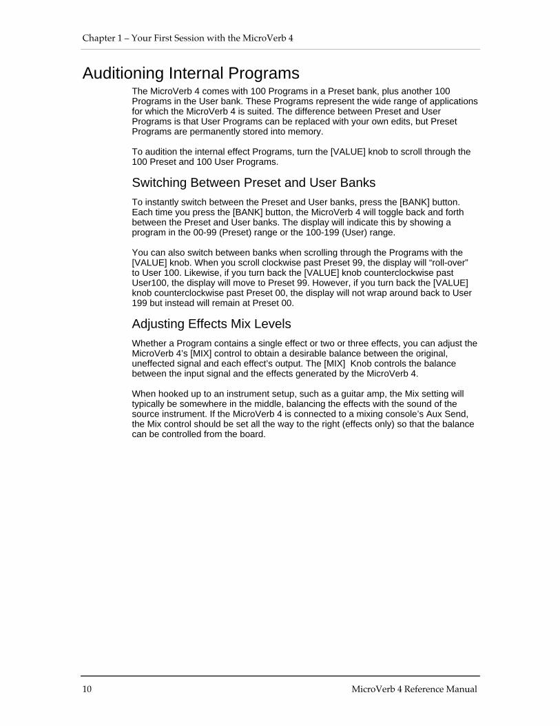
Auditioning Internal ProgramsThe MicroVerb 4 comes with 100 Programs in a Preset bank, plus another 100Programs in the User bank. These Programs represent the wide range of applicationsfor which the MicroVerb 4 is suited. The difference between Preset and UserPrograms is that User Programs can be replaced with your own edits, but PresetPrograms are permanently stored into memory.
To audition the internal effect Programs, turn the [VALUE] knob to scroll through the100 Preset and 100 User Programs.
Switching Between Preset and User BanksTo instantly switch between the Preset and User banks, press the [BANK] button.Each time you press the [BANK] button, the MicroVerb 4 will toggle back and forthbetween the Preset and User banks. The display will indicate this by showing aprogram in the 00-99 (Preset) range or the 100-199 (User) range.
You can also switch between banks when scrolling through the Programs with the[VALUE] knob. When you scroll clockwise past Preset 99, the display will “roll-over”to User 100. Likewise, if you turn back the [VALUE] knob counterclockwise pastUser100, the display will move to Preset 99. However, if you turn back the [VALUE]knob counterclockwise past Preset 00, the display will not wrap around back to User199 but instead will remain at Preset 00.
Adjusting Effects Mix LevelsWhether a Program contains a single effect or two or three effects, you can adjust theMicroVerb 4’s [MIX] control to obtain a desirable balance between the original,uneffected signal and each effect’s output. The [MIX] Knob controls the balancebetween the input signal and the effects generated by the MicroVerb 4.
When hooked up to an instrument setup, such as a guitar amp, the Mix setting willtypically be somewhere in the middle, balancing the effects with the sound of thesource instrument. If the MicroVerb 4 is connected to a mixing console’s Aux Send,the Mix control should be set all the way to the right (effects only) so that the balancecan be controlled from the board.

Your First Session with the MicroVerb 4 – Chapter 1
MicroVerb 4 Reference Manual 11
Storing Edited ProgramsOnce you are satisfied with the changes you have made to an edited Program, or arecreating a new Program from scratch, you will need to store your edited Programback into memory. The MicroVerb 4 will temporarily store the currently selectedProgram in non-volatile memory. If you edit a Program, the changes you made will belost the next time you power on the unit if you haven’t stored the edited Program intomemory. If you select another Program from memory before storing the editedProgram, your changes will also be lost.
✪ Although the MicroVerb 4 has two banks (Preset and User), you can only storePrograms in the User bank.
To store an edited Program:
¿ Press [STORE].
The Destination Program Number will flash. If the edited Program is from thePreset bank (Programs 00-99), the MicroVerb 4 will show the complementProgram in the User Bank (by adding 100 to the Program number.) Programscan only be stored to the location provided, i.e. there is no way to store an editedversion of Program 112 over Program 113.
¡ Press [STORE] again.
The LED Display will momentarily flash quickly, indicating that the Program hasbeen stored.
✪ Any changes you make to a Program are temporary, until you store those changesinto memory. If the Program you are editing is in the Preset bank, you must save thechanges you’ve made to a location in the User bank. If you recall another Program
before storing,your changes will be lost.
Bypassing EffectsAt any time you can bypass the effects, thereby allowing the direct signal to passthrough the MicroVerb 4 unchanged. This can be done in two ways:
• by turning the MIX knob all the way to the left,
• by connecting a footswitch to the [FOOTSWITCH] jack and pressing thefootswitch.
Each time the footswitch connected to the [FOOTSWITCH] jack is pressed, Bypassmode is toggled on and off again. For more information about Footswitches, seeChapter 2.

Chapter 1 – Your First Session with the MicroVerb 4
12 MicroVerb 4 Reference Manual

Connections – Chapter 2
MicroVerb 4 Reference Manual 13
CHAPTER 2
CONNECTIONSAC Power Hookup
The MicroVerb 4 comes with a power adapter suitable for the voltage of the country itis shipped to (either 110 or 220V, 50 or 60 Hz).
With the MicroVerb 4 off, plug the small end of the power adapter cord into MicroVerb4’s [POWER] socket and the male (plug) end into a source of AC power. It’s goodpractice to not plug in the MicroVerb 4 until all other cables are hooked up.
✪ Alesis cannot be responsible for problems caused by using the MicroVerb 4 or anyassociated equipment with improper AC wiring.
Line Conditioners and ProtectorsAlthough the MicroVerb 4 is designed to tolerate typical voltage variations, in today’sworld the voltage coming from the AC line may contain spikes or transients that canpossibly stress your gear and, over time, cause a failure. There are three main waysto protect against this, listed in ascending order of cost and complexity:
• Line spike/surge protectors. Relatively inexpensive, these are designed to protectagainst strong surges and spikes, acting somewhat like fuses in that they need tobe replaced if they’ve been hit by an extremely strong spike.
• Line filters. These generally combine spike/surge protection with filters thatremove some line noise (dimmer hash, transients from other appliances, etc.).
• Uninterruptible power supply (UPS). This is the most sophisticated option. A UPSprovides power even if the AC power line fails completely. Intended for computerapplications, a UPS allows you to complete an orderly shutdown of a computersystem in the event of a power outage, and the isolation it provides from thepower line minimizes all forms of interference—spikes, noise, etc.
Audio ConnectionsThe connections between the MicroVerb 4 and your studio are your music’s lifeline,so use only high quality cables. These should be low-capacitance shielded cableswith a stranded (not solid) internal conductor and a low-resistance shield. Althoughquality cables cost more, they do make a difference. Route cables to the MicroVerb 4correctly by observing the following precautions:
• Do not bundle audio cables with AC power cords.
• Avoid running audio cables near sources of electromagnetic interference such astransformers, monitors, computers, etc.
• Never unplug a cable by pulling on the wire itself. Always unplug by firmlygrasping the body of the plug and pulling directly outward.
• Do not place cables where they can be stepped on. Stepping on a cable may notcause immediate damage, but it can compress the insulation between the centerconductor and shield (degrading performance), or reduce the cable’s reliability.
• Avoid twisting the cable or having it make sharp, right angle turns.

Chapter 2 – Connections
14 MicroVerb 4 Reference Manual
• Although Alesis does not endorse any specific product, chemicals such as Tweekand Cramolin, when applied to electrical connectors, are claimed to improve theelectrical contact between connectors.
Typical ApplicationsThe analog audio inputs and outputs are typically used in one of three ways:
• from one or two effect/aux send outputs of a mixer, and out to the effect returninputs of the mixer; or,
• from a line-level instrument (like a guitar or keyboard with either a mono or stereooutput), and out to an amplifier or mixer input; or,
• from the stereo buss outputs of a mixer to a mix-down tape machine or amplifier.
When used with a mono source, the MicroVerb 4 is placed between the source andthe mixer/amplifier. Although the source may be mono, both the [LEFT/MONO] and[RIGHT] outputs can be connected to the inputs of a mixer/amplifier if stereoprocessing effects are desired. If using the effect sends of a mixer, you have theadvantage of sending any of the mixer’s input channels to the MicroVerb 4’s input(s),and have control over the level of each channel being sent.
These applications are outlined and illustrated in detail on the following pages.
Input Jack WiringThe MicroVerb 4’s [LEFT] INPUT jack is normalled to the [RIGHT] INPUT. Thismeans that if you only connect a single mono cable to the [LEFT] INPUT jack, it willalso be routed to the [RIGHT] INPUT. However, if anything is connected to the[RIGHT] INPUT jack, this normalized connection will be broken; therefore the [LEFT]INPUT jack feeds only the [LEFT] INPUT, and the [RIGHT] INPUT jack feeds only the[RIGHT] INPUT. Also, the [RIGHT] INPUT jack is NOT normalled to the [LEFT]INPUT.
LEFT/CH 1
RIGHT/CH 2
LEFT/CH 1
RIGHT/CH 2
Inputs Outputs
LEFT/CH 1
LEFT/CH 1
RIGHT/CH 2
Interfacing Directly with Instruments
J When connecting audio cables and/or turning power on and off, make sure that alldevices in your system are turned off and the volume controls are turned down.
The MicroVerb 4 has two 1/4” unbalanced inputs and two 1/4” unbalanced outputs.These provide three different audio hookup options:

Connections – Chapter 2
MicroVerb 4 Reference Manual 15
• Mono. Connect a mono cord to the [LEFT] INPUT of the MicroVerb 4 from amono source, and another mono cord from the [LEFT] output of the MicroVerb 4to an amplification system or mixer input.
MIXINPUT OUTPUT DUAL CHANNEL PARRELL PROCESSOR
00-99 PRESET 100-199 USER
CLIP
-6dB
-12dB
-32dB
L INPUT R
STORE
BANKMIDI
TO MIXING CONSOLE OR AMPLIFIER
LEFT OUTPUTLEFT/MONO INPUT
INSTRUMENT OR EFFECTS SEND
• Mono In, Stereo Out. While still using a mono input, you could connect twomono cords to the [LEFT] and [RIGHT] outputs of the MicroVerb 4 to a stereoamplification system or two mixer inputs.
MIXINPUT OUTPUT DUAL CHANNEL PARRELL PROCESSOR
00-99 PRESET 100-199 USER
CLIP
-6dB
-12dB
-32dB
L INPUT R
STORE
BANKMIDI
TO MIXING CONSOLE OR AMPLIFIER
RIGHT OUTPUTLEFT OUTPUTLEFT/MONO INPUT
INSTRUMENT OR EFFECTS SEND
• Dual Mono. Connect two mono cords to the [LEFT] and [RIGHT] inputs of theMicroVerb 4 from two mono sources , and two other mono cords from the [LEFT]and [RIGHT] outputs of the MicroVerb 4 to a stereo amplification system or twomixer inputs. This hookup allows discrete processing of the two channels, sincesome of the effects are discrete stereo to maintain stereo imaging.
• Stereo. Connect two mono cords to the [LEFT] and [RIGHT] INPUTS of theMicroVerb 4 from a stereo source , and two other mono cords from the [LEFT]and [RIGHT] OUTPUTS of the MicroVerb 4 to a stereo amplification system ortwo mixer inputs.
MIXINPUT OUTPUT DUAL CHANNEL PARRELL PROCESSOR
00-99 PRESET 100-199 USER
CLIP
-6dB
-12dB
-32dB
L INPUT R
STORE
BANKMIDI
TO MIXING CONSOLE OR AMPLIFIER
RIGHT OUTPUTLEFT OUTPUTLEFT/MONO INPUT
INSTRUMENT OR EFFECTS SEND
RIGHT INPUT

Chapter 2 – Connections
16 MicroVerb 4 Reference Manual
Interfacing to a Mixing Console
The MicroVerb 4 handles mono or stereo sends at all system levels. The inputcircuitry of the MicroVerb 4 can easily handle +4 dBu levels (+20 dBu peaks), whilehaving enough input and output gain to interface with the low -10 dBV signal levels ofbudget recording systems.
The MicroVerb 4 may be connected to a mixing console in several different ways. Itcan be used to effect several instruments at once by using the auxiliary send andreturn controls of the mixer. Another method of interfacing is to connect the unitdirectly to the insert send and return patch points of the channel that is to be effected.Still another way of interfacing the MicroVerb 4 to a mixer or recording console wouldbe in-line across the output of your mixing console. This last setup would be usedonly if you wanted effects on the entire mix.
Using Aux Sends
Generally, mixing consoles provide two types of auxiliary sends: pre-fader sends forcreating a cue (headphone) mix, and individual, post-fader effect sends. Typically, if amixer has more than two sends per channel (4, 6 or 8, perhaps), the first two sendsare reserved for the cue sends, while the remaining sends are used to feed effects,such as the MicroVerb 4. If you are using a mixer with more than two sends, connectthe MicroVerb 4 using post-fader sends.
Using a mixer’s aux sends poses a distinct advantage: each channel has its ownlevel control feeding the aux output (and eventually the MicroVerb 4 input). Thisallows you to make a mix of any channels you want to go to the effects by using theindividual channels’ aux send levels on the mixer. Most consoles also have auxmaster controls, which set the overall level of each aux output.
Coming back from the MicroVerb 4’s outputs into the mixer, you have two options:
• connecting to dedicated return inputs, or
• connecting to channel inputs.
The former is good if your mixer provides dedicated inputs (called returns) for effectdevices like the MicroVerb 4. If your mixer does not have these, or you have alreadyused them all, consider connecting the MicroVerb 4 to channel inputs (if there are anyremaining). This method gives you the added bonus of more panning options and EQon the effects.
No matter where you connect the output of the MicroVerb 4 into the mixer, you are incontrol of the balance between the mixer’s channel inputs (the uneffected signalbeing routed to the aux sends and the Mix), and the effect returns coming from theMicroVerb 4. The effect returns generally should only contain effected signal, and nothave any uneffected signal mixed with it (since these two signals are blendedtogether at the mixer). Therefore, it may be necessary to modify the mix so that onlyeffected signal is present at the MicroVerb 4’s outputs. To do this, turn the Mix controlall the way to the right.

Connections – Chapter 2
MicroVerb 4 Reference Manual 17
Mono In - Stereo Out. If you only want to feed the MicroVerb 4 a mono input, butwish to connect both of its outputs back to the mixer, you will need three 1/4" audiocables. Connect a mono cord from an effect send to the [LEFT] input of theMicroVerb 4, another mono cord from the [LEFT] output of the MicroVerb 4 to aneffect return or other mixer input, and another mono cord from the [RIGHT] output ofthe MicroVerb 4 to an adjacent effect return or mixer input.
MIXINPUT OUTPUT DUAL CHANNEL PARRELL PROCESSOR
00-99 PRESET 100-199 USER
CLIP
-6dB
-12dB
-32dB
L INPUT R
STORE
BANKMIDI
LEFT/MONO INPUT
LEFTOUTPUT
RIGHTOUTPUT
AUX SEND 1
MIXERAUX RETURNS OR INPUT CHANNELS
Stereo In - Stereo Out. This connection is similar to the one described above.However, by utilizing two sends from the mixer, we add one more cord and can nowsend a stereo signal to the MicroVerb 4’s inputs. For example, if you connectedsends 3 and 4 to the [LEFT] and [RIGHT] inputs, and had a stereo instrument (suchas a keyboard) connected to two channel inputs of the mixer (either one panned hardleft and hard right), you would send the left channel to send 3 and the right channel tosend 4. This is especially useful on the Dual Send Programs, #90-99 and 190-199.
MIXINPUT OUTPUT DUAL CHANNEL PARRELL PROCESSOR
00-99 PRESET 100-199 USER
CLIP
-6dB
-12dB
-32dB
L INPUT R
STORE
BANKMIDI
LEFT/MONO INPUT
LEFTOUTPUT
RIGHTOUTPUT
AUX SEND 1
MIXERAUX RETURNS OR INPUT CHANNELS
AUX SEND 2
RIGHT INPUT
Using Inserts

Chapter 2 – Connections
18 MicroVerb 4 Reference Manual
By using individual channel inserts, you can dedicate the MicroVerb 4 to a specificchannel (or pair of channels) on the mixer. The Insert connections on the back of themixer provide a way of “inserting” external processing equipment into the signal path.The insert occurs after the input amplifier, and before the main fader; essentially it isthe same as connecting the source (instrument or microphone) into the MicroVerb 4before the mixer’s channel input. However, some mixing console’s inserts come afterthe EQ section, and may therefore be different from the original signal. If nothing isconnected to the channel’s Insert jack, the signal is not routed there.
Usually, insert connections require a special, stereo-splitting Y-cord to be connected(one stereo plug provides both send and return while two mono plugs connectseparately to the effects unit’s input and output). These are known as TRS connectors(tip-ring-sleeve). The tip of the stereo plug carries the send or output of the insert jack,while the ring carries back the return. The sleeve represents a common ground for bothsignals.
Mono. This involves connecting a 1/4" TRS (tip-ring-sleeve) Y-cable to the Insert jackof a single channel on a mixing console. The other end of the cable (which splits intotwo, 1/4" mono connectors) are connected to the [LEFT] input and [LEFT] output,respectively. If you do not hear any audio after making these connections, swap theinput and output cables at the MicroVerb 4, as these may be wired backwards. If thecable is color-coded, usually the red jack represents the send (which connects to theMicroVerb 4’s input) and black is the return (which connects to the output).
MIXER
INSERT
LEFT OUTPUTMIXINPUT OUTPUT DUAL CHANNEL PARRELL PROCESSOR
00-99 PRESET 100-199 USER
CLIP
-6dB
-12dB
-32dB
L INPUT R
STORE
BANKMIDI
LEFT/MONO INPUT
Using Main Outputs
When you want to add effects to everything on the mixer, you can connect theMicroVerb 4 between the mixer’s outputs and the amplifier’s or tape machine’s

Connections – Chapter 2
MicroVerb 4 Reference Manual 19
inputs. This is done by using two 1/4" mono cables to connect the Left and RightMain Outputs of the mixing console to the [LEFT/MONO] and [RIGHT] inputs of theMicroVerb 4. The [LEFT] and [RIGHT] outputs of the MicroVerb 4 are then connectedto a stereo amplifier, or two input channels of another mixing console (for sub-mixingapplications).
MIXINPUT OUTPUT DUAL CHANNEL PARRELL PROCESSOR
00-99 PRESET 100-199 USER
CLIP
-6dB
-12dB
-32dB
L INPUT R
STORE
BANKMIDI
RIGHT INPUTLEFT/MONO INPUT
LEFT OUTPUT RIGHT OUTPUT
RIGHT INPUT
POWER AMP
LEFT INPUT
RIGHTMASTEROUT
MIXER
LEFTMASTEROUT

Chapter 2 – Connections
20 MicroVerb 4 Reference Manual
Avoiding Ground LoopsIn today’s studio, where it seems every piece of equipment has complex routing andcomputer logic, there are many opportunities for ground loop problems to occur.These show up as hums, buzzes or sometimes radio reception and can occur if apiece of equipment “sees” two or more different paths to ground. While there aremethods to virtually eliminate ground loops and stray radio frequency interference,most of the professional methods are expensive and involve installing a separatepower source just for the sound system. Here are some easy helpful hints that aprofessional studio installer might use to keep those stray hums and buzzes to aminimum.
¿ KEEP ALL ELECTRONICS OF THE SOUND SYSTEM ON THE SAME ACELECTRICAL CIRCUIT. Most stray hums and buzzes happen as a result ofdifferent parts of the sound system being plugged into outlets of different ACcircuits. If any noise generating devices such as air conditioners, refrigerators,neon lights, etc., are already plugged into one of these circuits, you then have aperfect condition for stray buzzes. Since most electronic devices of a soundsystem don’t require a lot of current (except for power amplifiers), it’s usually safeto run a multi-outlet box or two from a SINGLE wall outlet and plug in all of thecomponents of your system there.
¡ KEEP AUDIO WIRING AS FAR AWAY FROM AC WIRING AS POSSIBLE. Manyhums come from audio cabling being too near AC wiring. If a hum occurs, trymoving the audio wiring around to see if the hum ceases or diminishes. If it’s notpossible to separate the audio and AC wiring in some instances, make sure thatthe audio wires don’t run parallel to any AC wire (they should only cross at rightangles, if possible).
¬ TO ELIMINATE HUM IF THE ABOVE HAS FAILED:A) Disconnect the power from all outboard devices and tape machines except
for the mixer and control room monitor power amp.B) Plug in each tape machine and outboard effects device one at a time. If
possible, flip the polarity of the plug of each device (turn it around in thesocket) until the quietest position is found.
C) Make sure that all of the audio cables are in good working order. Cables witha detached ground wire will cause a very loud hum!!
D) Keep all cables as short as possible, especially in unbalanced circuits.
If the basic experiments don’t uncover the source of the problem, consult your dealeror technician trained in proper studio grounding techniques. In some cases, a “stargrounding” scheme must be used, with the mixer at the center of the star providingthe shield ground on telescoping shields, which do NOT connect to the chassisground of other equipment in the system.

Connections – Chapter 2
MicroVerb 4 Reference Manual 21
MIDIMIDI (Musical Instrument Digital Interface) is an internationally-accepted protocol thatallows musical-related data to be conveyed from one device to another. The MIDIconnections on the MicroVerb 4 provide four different functions:
• To recall Programs using MIDI program change messages
• To control (modulate) parameters inside the MicroVerb 4 in realtime via MIDIcontrollers (example: A keyboard’s mod wheel, or pedals, etc.)
• To send and receive SysEx (System Exclusive) dumps of individual programs orthe entire bank of programs for storage and retrieval purposes
• To pass-on MIDI information thru the MicroVerb 4 to another MIDI device.
To connect the MicroVerb 4’s MIDI ports to another MIDI device:
¿ Connect a MIDI cable from the MicroVerb 4’s MIDI [IN] connector to the otherMIDI device’s MIDI OUT connector.
¡ Connect another MIDI cable from the MicroVerb 4’s MIDI [OUT/THRU] connectorto the MIDI IN connector of the other MIDI device.
Note: It is not necessary to follow step 2 if you intend to only send information to theMicroVerb 4, and do not need to receive information back from it. Example: If youonly want to be able to recall Programs using MIDI program change messages, thereis no need to connect a cable to the MicroVerb 4’s [OUT/THRU] connector. For moreinformation about MIDI and Modulation, refer to chapter 5.
FootswitchOn the rear panel you will find a footswitch jack labeled [FOOTSWITCH]. This is aStereo jack, with connections for both a normal Bypass jack and for two footswitchjacks. All footswitches must be plugged in before the MicroVerb 4 has its powerturned on.
To hook up a single Bypass Footswitch: Any momentary footswitch can beplugged into the Footswitch input on the MicroVerb 4. The extra connector on thefootswitch jack will simply be ignored.
To hook up two Footswitches: The MicroVerb 4 is equipped with a 1/4” TRSfootswitch jack which can connect to two footswitch jacks. To connect bothfootswitches, first locate a cable or adapter which has one male 1/4” TRS jack andtwo female 1/4” mono jacks. This cable is available from several manufacturers, suchas Radio Shack (#274-302) and Hosa (YPP-118).
The footswitch connected to the tip of this jack will function as a Bypass pedal. Thefootswitch connected to the center ring of this jack will function as a Control pedal.(See below.) You may also use a dual footswitch, which has two pedals on one

Chapter 2 – Connections
22 MicroVerb 4 Reference Manual
assembly with a stereo cord already attached. The pedals are often packaged withdigital pianos.
You should not use the dual footswitch from a guitar amplifier, as these are typicallylatching type footswitches. You can tell a latching footswitch from an unlatched typewhen it takes two presses to enable any of the functions (Bypass, etc.). Also, thesefootswitches usually “click” when stepped on. Use only Momentary (non-latching)footswitches with the MicroVerb 4.
If desired, a mono footswitch can be plugged half way (to the first “click”) to functionas a Control Footswitch only.
Bypass Footswitch . Pressing the footswitch will toggle Bypass mode on and off.When Bypass mode is activated, the effects will mute and the Display will read “bYP”and then dim. Bypass turns off any effects going to the output, and is useful forturning off delay for a certain part of a song, for example.
Control Footswitch. When a footswitch is connected to the ring of the 3 connectorFootswitch jack, it functions as a Control footswitch. This footswitch has 2 differentfunctions, depending on the type of effect it is used on.
On a Lezlie Effect: The control footswitch controls the Lezlie speed. When it ispressed, the display will either read ffFSt or SLO and the rotating speaker willramp up to the Fast or down to the Slow speed, respectively.
On a Delay Program: The Control footswitch acts as a “Tap Tempo” control.Tapping on the footswitch in tempo with the music will create a 1/4 note delayin tempo with the song. The display will briefly display the Delay Time (inmilliseconds).
When the selected Program is not a Lezlie or Delay Program, pressing the Controlfootswitch will have no effect.
Tap From Audio. If the Control footswitch is held down and audio is played into theinputs, these impulses will be used to set the delay time. For example, hold down theControl footswitch on a delay program and play two staccato notes on a guitar,keyboard, etc. The delay time will be set for the time between these two sounds.Make sure that the level of these impulses are at least -6dB on the front panel meters(the third segment up) so that the MicroVerb 4 has sufficient level to trigger from.Tip: High notes work better than low notes when using this feature.

Overview of Effects – Chapter 3
MicroVerb 4 Reference Manual 23
CHAPTER 3
OVERVIEW OF EFFECTSReverb Effects
Reverb is made up of a large number of distinct echoes, called reflections. In anatural acoustic space, each reflection’s amplitude and brightness decays over time.This decaying action is influenced by the room size, the location of the sound sourcein the room, the hardness of the walls, and many other factors. The MicroVerb 4offers the following types of reverberation:
Concert Hall (Programs 00-09, 100-109)This is a simulation of a large concert hall. Halls tend to be large rooms with lots ofreflective surfaces, where sounds can swim around, changing timbre over time. Thisis a classic reverb which sounds good on just about anything. Try it on vocals, drums,acoustic, electric, or orchestral instruments.
Real Room (Programs 10-19, 110-119)This algorithm gives you the sound of a medium size studio room. This algorithmuses a lot of processing power for a rich sound and smooth decay. It has a punchier,bigger sound than a Hall reverb, which makes it good for Rock and Dance music. Theattack is also more reflective. It sounds good on drums, keyboards and guitars. Thistype also includes Nonlinear, Gated, and Reverse reverbs. for percussion andeffects.
Plate Reverb (Programs 20-29, 120-129)This is a simulation of a classic echo plate, a 4' by 8' suspended sheet of metal withtransducers at either end used to produce reverb. Popular in the 1970’s, it still prizedfor its transparent sound, particularly on vocals and guitars. It works well for a lushlead vocal, piano, or guitar, especially when looking for a classic rock and roll sound.
Reverb ParametersDecay (Edit A)The Reverb Decay determines how long the Reverb will sound before it dies away.Turning up the Reverb Decay will have the effect of increasing the rooms size.Generally, Classical, Jazz, and Ballad styles will use longer decay times than Uptempo Rock or Dance music. The LCD display will show the Decay time in Secondsand Milliseconds.
Hi Cut (Edit B)The Hi Cut filter can be set between 059 Hz and 36.2 kHz or OFF, and attenuates allfrequencies above this value by 6dB per octave. The lower the setting, the less highfrequencies of the input are allowed to pass thru to the reverb effect. This controls theoverall character of the room. Try a brighter sound on vocals, drums, and percussion,and a darker sound (i.e. lower Hi Cut frequency) on Acoustic Guitar, Piano, andStrings.
Chorus/Flange Effects (Programs 30-49, 130-149)The Chorus and Flange effects alter the pitch and delay of a signal in various ways toproduce “layered” timbres that are more complex than the original signal. Although

Chapter 3 – Overview of Effects
24 MicroVerb 4 Reference Manual
some of these effects can sound similar to one another depending on the parametersettings, each is achieved differently and can be quite dramatic under the rightcircumstances. Pitch effects are achieved by splitting the signal into at least twoparts, effecting the pitch of one of the parts, then mixing them back together. Thiseventual mixing is essential since the overall sound of the effect is achieved by thedifference between the dry, uneffected signal and the effects signal. Therefore, whenusing Chorus or Flange, it’s best to keep the Mix control around 50%. Also includedin this bank is Auto Pan, which pans a mono signal from Left to Right. This type ofeffect works best with the Mix control set 100% wet. The various types of Chorus andFlange are:
Stereo ChorusThe Chorus effect is achieved by splitting the signal into three parts with a dry signaland a separate Detuning section for both left and right channels. The detuning isfurther effected by being modulated by an LFO (low frequency oscillator) whichcauses the detuning to vary. Many variables are available in this scheme: thePredelay can be varied, the LFO depth can be varied, the LFO speed can be varied,and a portion of the detuned signal can be fed back to the input to increase the effect.Finally, the waveform shape of the LFO can be changed from a smooth sine wave, toa more abrupt squarewave to make the pitch detuning more pronounced.
Some of the MicroVerb 4’s Choruses have individual LFOs controlling the Left andRight sides, set at different rates. These effects, called True Stereo Choruses, oftenhave a wider stereo image than regular Stereo Chorus effects. When the Rate ischanged on a True Stereo Chorus, the frequency difference between the Left andRight sides is maintained. Note: These Choruses process the Left and Right sidesindividually, so any stereo imaging will be maintained.
LFO
DETUNE
DELAYDRYSIGNAL
RIGHTCHORUSED
OUTPUTFEEDBACK
DETUNE
FEEDBACK
DRY SIGNAL
DRY SIGNAL
LEFTCHORUSED
OUTPUT
Quad ChorusQuad Chorus modulates four delayed signals, each with its phase offset by 90∞. Itgives you twice as much modulation effect as the Stereo Chorus, so it’s great forreally fattening up a sound.
Chorus
Overview of Effects – Chapter 3
MicroVerb 4 Reference Manual 25
This is a less processor intensive version of the Stereo Chorus, used in Multi Effectconfigurations. The effect of Chorusing is achieved by splitting and slightly delayingone part of the signal, then varying the time delay with an LFO. The delayed signal isthen mixed back with the original sound to produce a thicker, warmer sound.
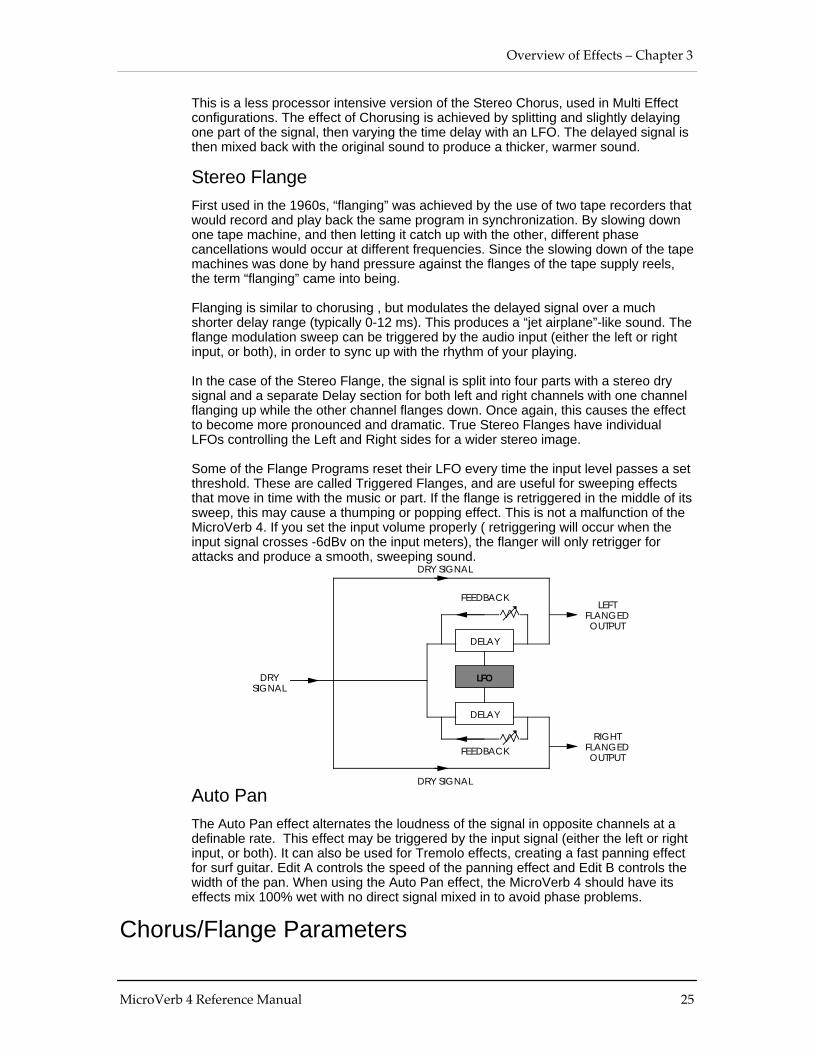
Stereo FlangeFirst used in the 1960s, “flanging” was achieved by the use of two tape recorders thatwould record and play back the same program in synchronization. By slowing downone tape machine, and then letting it catch up with the other, different phasecancellations would occur at different frequencies. Since the slowing down of the tapemachines was done by hand pressure against the flanges of the tape supply reels,the term “flanging” came into being.
Flanging is similar to chorusing , but modulates the delayed signal over a muchshorter delay range (typically 0-12 ms). This produces a “jet airplane”-like sound. Theflange modulation sweep can be triggered by the audio input (either the left or rightinput, or both), in order to sync up with the rhythm of your playing.
In the case of the Stereo Flange, the signal is split into four parts with a stereo drysignal and a separate Delay section for both left and right channels with one channelflanging up while the other channel flanges down. Once again, this causes the effectto become more pronounced and dramatic. True Stereo Flanges have individualLFOs controlling the Left and Right sides for a wider stereo image.
Some of the Flange Programs reset their LFO every time the input level passes a setthreshold. These are called Triggered Flanges, and are useful for sweeping effectsthat move in time with the music or part. If the flange is retriggered in the middle of itssweep, this may cause a thumping or popping effect. This is not a malfunction of theMicroVerb 4. If you set the input volume properly ( retriggering will occur when theinput signal crosses -6dBv on the input meters), the flanger will only retrigger forattacks and produce a smooth, sweeping sound.
LFO
DELAY
DRYSIGNAL
RIGHTFLANGEDOUTPUT
FEEDBACK
DELAY
FEEDBACK
DRY SIGNAL
DRY SIGNAL
LEFTFLANGEDOUTPUT
Auto PanThe Auto Pan effect alternates the loudness of the signal in opposite channels at adefinable rate. This effect may be triggered by the input signal (either the left or rightinput, or both). It can also be used for Tremolo effects, creating a fast panning effectfor surf guitar. Edit A controls the speed of the panning effect and Edit B controls thewidth of the pan. When using the Auto Pan effect, the MicroVerb 4 should have itseffects mix 100% wet with no direct signal mixed in to avoid phase problems.
Chorus/Flange Parameters

Chapter 3 – Overview of Effects
26 MicroVerb 4 Reference Manual
Rate (Edit A)The Rate control sets the speed of the Chorus or Flanging sweep. When the Edit Aknob is turned, the LCD display will show the edited sweep frequency in Hertz.
Depth (Edit B)The Depth control sets the intensity of the Chorus or Flanger sweep. The LCDdisplay will show the depth in a scale from 0 to 127 (0-125 for Flangers). Tip: FasterChoruses or Flangers typically sound better with a shallower depth than slower ones.
Delay Effects (Programs 50-59, 150-159)Delay is a discrete echo repeat, unlike the rapid wash of repeats that create reverbeffects. It is useful for adding depth to a track or performance if a reverb is muddyingup the mix. There are several types of Delay in the delay bank:
Mono DelayThis subtype provides a delay of up to 1270 ms. The delay time can be adjustedseparately by 10 millisecond increments. Feedback is also available to increase thenumber of delay repeats.
Stereo DelayThis Single Configuration provides two separate delays. Typically, the Edit A knobcontrols one side, and the other changes in proportion. The delay time can beadjusted separately by 5 ms increments.
Ping Pong DelaySo called because the output bounces from left to right in stereo with the speeddetermined by the delay time. The delay can be adjusted in 5 ms increments, andfeedback is adjustable from 0-99%.
MultiTap DelayThis is like having three delays at once. They are usually arranged in a rhythmicdelay pattern. The Edit A knob scales all of the delay times so that you can make thedelay rhythm fit the tempo of a song.
Delay Parameters
Time (Edit A)This control sets the time between the input signal and the first delay tap. On theMulti Tap Delay and Stereo Delay programs, the Edit A knob will scale all of thedelays by a percentage. The LCD display will show you the delay time in Secondsand Milliseconds, or (in the case of Multi Tap and Stereo Delays) percentage of thetime scaling.
Feedback (Edit B)After a signal has gone through the delay processing, it is fed back to the delay input.The Feedback control sets what percentage of the signal will go back through thedelay. At a setting of 0%, no signal will go back through the delay, so only one delay

Overview of Effects – Chapter 3
MicroVerb 4 Reference Manual 27
tap will be heard. At a setting of 10%, only a little signal will be fed back through thedelay, so the signal will repeat back a few times before fading into silence. At aFeedback setting of 100%, the signal will continue repeating for a few minutes beforedecaying into silence.
Setting Delay Time Using Tap TempoYou can adjust the delay time using a technique called “tap tempo”. If you connect afootswitch to the ring of the Footswitch jack, it can be used as for Tap Tempo. (SeeChapter 2, “Footswitch”, for connection instructions.) By tapping on the “Control”footswitch in tempo with the song, you can get a delay which repeats in time with themusic.
The MicroVerb 4 can also set its Delay Time by playing audio into the Inputs. To setthe delay time using this method, hold down the Control Footswitch and play somequick notes into the MicroVerb 4. See Chapter 2, “Footswitch”, for details.
Pitch Shifter Effects (Programs 60-69, 160-169)The Pitch shifter in the MicroVerb 4 takes the Pitch of the input signal and shifts ithigher or lower by a fixed amount. Pitch shifters are useful for creating instant parallelharmonies and for creating subtle chorusing effects. The Pitch Shifters in theMicroVerb 4 include:
Stereo Pitch ShifterThe Pitch Shifter effect transposes the pitch of the incoming signal by a fixed amount.It is useful for creating parallel harmonies, detuning, chorusing, and special effects.The Semi (Edit A) parameter shifts the pitch in increments of one half step, with arange of up or down one octave. The Fine (Edit B) parameter detunes the signal invery fine increments, with a range of up or down one half step.
Stereo Pitch DetunerThe Pitch Detuner has a range of plus or minus one half step in increments on 1 cent.It is useful for a slight chorus effect or for Half step shifts. The Shift L (Edit A) andShift R (Edit B) parameters control the shift of the Left or Right output.
Multi Effects (Programs 70-89, 170-189)There are several Multieffect Programs in the MicroVerb 4. A multieffect can besimply described as 2 or three effects at once. This typically involves a pitch effectwith reverb, such as Stereo Chorus into a Hall, or something more esoteric such asLezlie into a room.
CHORUS DELAY REVERBDRY SIGNAL TO OUTPUTS
LezlieWith the Lezlie effect , the pitch change block becomes a rotating speaker simulator.This effect was extremely popular during the 1960’s and was achieved bymechanically rotating the speakers to produce complex timbral changes. The Lezliespeaker system is most often used with tone-wheel organs, but is occasionally usedfor guitar amplification as well. When changing the speed between fast and slow, the

Chapter 3 – Overview of Effects
28 MicroVerb 4 Reference Manual
effect will ramp rather than change abruptly, just as a true Lezlie speaker systemwould do.
Multi Effects Parameters:Decay (Edit A)The Decay parameter controls the length of the Reverb. When adjusted, the LCDdisplay will show the decay time in Seconds and Milliseconds.
Rate/Time (Edit B)The Rate/Time parameter controls the rate of a Chorus or Flange, the Delay Time ofa Delay, or the Motor Speed of a Lezlie, depending which is active in the Program. Inthe case where three effects are active at once, Chorus/Delay/Reverb for example,Edit B controls the Delay Time.
Dual Send Effects (Programs 90-99, 190-199)The Dual Send programs all have two different effects. These effects are each fed byone of the inputs so that they can be used independently.
CHORUSLEFT INPUT
RIGHT INPUT REVERB
LEFT OUTPUT
RIGHT OUTPUT
This is an ideal setup for someone using the MicroVerb 4 with a mixer. By hookingtwo of the Aux Sends into the Left and Right inputs of the MicroVerb 4, you can use itto provide two discrete effects. Some of the multi effects include:
Reverb/DelayThe Left Input of the MicroVerb 4 feeds a Room reverb and the Right Input feeds aMono Delay. The Edit A knob controls Reverb Decay (displayed in seconds) and theEdit B knob controls Delay time (also in seconds).
Reverb/ChorusThe Left input again feeds a Room reverb, and the Right side feeds a Stereo Chorus.The Edit A knob controls Decay time (in seconds) and the Edit B knob controlsChorus Rate (in Hertz). This Dual send Chorus has two individual LFOs panned hardleft and hard right for a wide sound, and when the rate is changed the differencebetween the two rates will stay constant.
Reverb/FlangeThe Left input again feeds a Room reverb and the Right input feeds a Stereo Flanger.Edit A controls the Reverb Time (in seconds) and Edit B controls the Flanger Rate (inHertz).

Overview of Effects – Chapter 3
MicroVerb 4 Reference Manual 29

Chapter 1 – Your First Session with the MicroVerb 4
30 MicroVerb 4 Reference Manual

Description of Controls – Chapter 4
MicroVerb 4 Reference Manual 31
CHAPTER 4
DESCRIPTION OF CONTROLSFront Panel
Input LevelThe Input Level controls the level of the signal being fed into the MicroVerb 4. TheMicroVerb 4 can operate with signal levels anywhere from +4dBv Pro Audio gear toguitar level signals. To set the input level, watch the Input Meters while adjusting theInput level (see below).
Mix LevelThe Mix Level controls the balance between the uneffected signal coming through theinputs and the effects being generated by the MicroVerb 4. When the Mix is turned allthe way to the left, the input signal will be sent straight to the output with no effectsadded. When the Mix is turned all the way to right, only the effects will be sent to theoutputs with none of the original input signal mixed in. By keeping the Mixsomewhere in the center, a blend of dry and wet signal can be achieved.
With a typical instrument setup (use with a guitar amp, etc.) the Mix is usually setaround 12 o’clock. When used with a mixing console, the Mix control should beturned all the way to the right (full wet) so that the effects mix can be controlled fromthe mixer.
Output LevelThe Output Level controls the volume of the signal from the output of the MicroVerb4. The optimum level for this control is 75%, but it can be raised or lowered asnecessary.
Level MetersThese peak-style meters monitor the signal strength of the unprocessed inputs, andare used in much the same way as the level meters on a standard tape recorder.Since the MicroVerb 4 is a True Stereo device, both the Left and Right inputs areshown separately as they may be performing different functions. When the red “Clip”LEDs are lit, the input signal may be distorted so the Input level should be backed off.If the bottom “-32dB” LEDs are barely coming on, the input signal is not high enoughand the resulting sound from the MicroVerb 4 may be noisy. Ideally, the Input signallevel should be set so that the input lights the first two or three LEDs.
The “Clip” indicators may light up even if the signal level has not passed the -6dBlevel. If this happens, it means that the signal is clipping internally, probably on aregenerating program like a reverb or a flange with lots of feedback. If this happenssimply back off the Input level until the problem goes away.
LED DisplayWhen the MicroVerb 4 is first turned on, it will always cycle through a simple testmode. First, all LED segments in the display will light up. Then, it will display thesoftware version installed (i.e. 1.00). Finally, it will return to the Program Number

Chapter 4 – Description of Controls
32 MicroVerb 4 Reference Manual
which was last selected. (Note: When the MicroVerb 4’s power is disconnected, anyedits to the currently selected Program will be lost.)
The MicroVerb 4’s display is used to indicate the following:
¿ Program Number. MicroVerb 4 Programs are numbered from 00 to 199.Programs 0-99 are Preset programs and 100-199 are User Programs. Unlesssome parameter on the MicroVerb 4 is being edited, the Program Number willalways be displayed in its normal illumination. The only exception to this is whenthe MicroVerb 4 is bypassed with a footswitch; when the unit is bypassed theProgram Number will be shown with the display dimmed.
¡ MIDI Channel. When the [BANK/MIDI] button is held down, the Display will dimand the current MIDI Channel will be reported. The MIDI Channel can then beedited by turning the Value wheel while the Bank/MIDI button is held. PossibleMIDI Channels are 00 (Omni), and 01-16.
¬ Overwrite Program Number. When the [STORE] button is pressed, the Programabout to be saved over will flash. Only User Programs can be Stored over, so if[STORE] is pressed while editing a Preset Program the MicroVerb 4 will add 100to the Program number for storage. When the Store button is pressed again toconfirm, the Program number will flash rapidly and then return to the normalProgram Number display.
÷ Parameter Value. When the [EDIT A] or [EDIT B] knobs are turned, the LEDdisplay will dim and show the new value for that parameter. For example, whenEdit A is adjusted on a Hall programs, the display will briefly show the newReverb Time in seconds and milliseconds, then return to the Program number.
STORE ButtonEither Preset or User Programs can be temporarily edited using the Edit A and Edit Bknobs. If you wish to store these edits for later recall, press the [STORE] button. Ifyou have edited a User Program, that Program number will start flashing. If you haveedited a Preset Program, the complementary User Program number (that Programplus 100) will start flashing, since Presets cannot be saved over. This is the Programnumber which is about to be overwritten. By pressing the [STORE] button again, youtell the MicroVerb 4 to actually store the Program. The Program number will flashrapidly and then return to the normal Program Number display.
BANK/MIDI ButtonThis button serves three functions. To switch between the Preset Bank and the Userbank, press and release the Bank button. The Program number will either increase ordecrease by 100 as the unit switches banks. If the Bank/MIDI button is pressed andheld for a moment, the current MIDI channel will be displayed. If the Value knob isturned while the Bank/MIDI button is being pressed, the MIDI channel can beadjusted. Finally, to dump the memory of the MicroVerb 4 to a sequencer or programlibrarian program, DataDisk, etc., hold the Bank/MIDI button until the MIDI channel isdisplayed and press [STORE]. The contents of the User bank will be sent to the MIDIoutput.
VALUE KnobWhen no other button is being pressed, the Value Knob is used to change Programs.If the Bank/MIDI button is held while the Value Knob is being turned, the MicroVerb 4will change its MIDI channel.

Description of Controls – Chapter 4
MicroVerb 4 Reference Manual 33
Edit A/ Edit B KnobsThe Edit A and Edit B knobs are used to adjust aspects of the currently selectedProgram. For example, on a Concert Hall program, the Edit A knob adjusts ReverbDecay Time and the Edit B knob adjusts Reverb Input Hi Cut. When the Edit A or EditB knobs are adjusted, the new parameter registers briefly on the display.

Chapter 4 – Description of Controls
34 MicroVerb 4 Reference Manual
Rear PanelPowerThis is a plug for connecting the Alesis Model P3 +9VAC power supply (supplied).The power supply is then connected to an AC outlet delivering a nominal 120VAC.The correct power supply must be used AT ALL TIMES. Any other power supplymight create a fire risk and/or permanently damage your unit. This damage wouldNOT be covered under your warranty.
FootswitchThis is a 1/4" stereo phone jack which connects to one or two momentary (notlatching) footswitches, either normally-open or normally-closed.
• When one footswitch is plugged into the Footswitch jack, it will function as aBypass footswitch. When the Footswitch is pressed, the display will read “bYP”,the display will dim, and the MicroVerb 4 will stop producing effects. If thefootswitch is pressed again, effects output will continue.
• Two footswitches can be connected if a simple adapter cable is used, similar toan Insert cable:
When this setup is used, the footswitch connected to the Tip functions as aBypass footswitch. The footswitch connected to the Ring functions as a Controlfootswitch. For more information, see Chapter 2, “Footswitch”.
MIDI InThis is a 5-pin DIN standard MIDI plug which connects to any MIDI compatibleequipment such as a MIDI sequencer that will send program changes and controllerinformation to the unit.
MIDI Out/ThruThis is a 5-pin DIN standard MIDI plug which connects to any MIDI compatibleequipment such as a keyboard or another effects device. It is provided for sendingsystem exclusive commands for storing programs. It also relays all messagesreceived on the [MIDI IN].
Input (Left/Mono & Right)

Description of Controls – Chapter 4
MicroVerb 4 Reference Manual 35
These are 1/4" phone jacks which connect to sources such as the effects sends ofmixing consoles. They may be used with nominal input levels from -10dBV (guitarlevel) to +4dBu. For mono applications, use the [LEFT/MONO] input.
The [LEFT/MONO] input jack is normalled to the [RIGHT] jack. This means that whennothing is plugged into the [RIGHT] input jack, the signal present at the[LEFT/MONO] input is routed to the [RIGHT] as well.
Output (Left & Right)These are 1/4" phone jacks which connect to devices such as the effects returns on amixing console or Power Amplifier Inputs. For mono applications, use the [LEFT]output.

Chapter 1 – Your First Session with the MicroVerb 4
36 MicroVerb 4 Reference Manual

Advanced Applications – Chapter 5
MicroVerb 4 Reference Manual 37
CHAPTER 5
MIDI APPLICATIONSMIDI Functions
The MicroVerb 4 provides many MIDI functions, including being able to respond toprogram changes, sending and receiving Program information via SysEx (SystemExclusive) dumps, and realtime control over effect parameters via MIDI controllers.For more information about basic MIDI connections, see Chapter 2.
MIDI ChannelThe MIDI Channel is used to receive program change messages, as well as otherMIDI events for use with the realtime modulation capabilities in the MicroVerb 4.
To set the MicroVerb 4’s MIDI channel:
¿ Press and hold [BANK/MIDI].The Display will dim and display the current MIDI channel.
¡ Turn the [VALUE] knob to set the MIDI Channel to either 01 through16, or 00 forOmni mode (receives on all 16 channels simultaneously).
MIDI ThruThe MicroVerb 4 automatically sends information from the MIDI IN to the MIDIOUT/THRU. In order to pass on MIDI information from a control device thru theMicroVerb 4 to another MIDI device, connect the control device’s MIDI OUT to theMicroVerb 4’s [MIDI IN]. Then connect the MicroVerb 4’s [MIDI OUT/THRU] to theMIDI IN of the other device you wish to control.
If too much information is being sent thru the MicroVerb 4, the internal buffer mayoverflow. If this happens, the front panel will read FLO and some data going to thereceiving unit may be lost. Alesis recommends that any dense MIDI information(SysEx, Midi Time Code, etc.) be routed directly to the receiving unit using a MIDIPatchbay instead of relying on the Thru port of the MicroVerb 4.
Receiving Program ChangesIn order to recall programs on the MicroVerb 4 from a MIDI controller device :
¿ Connect the control device’s MIDI OUT to the MicroVerb 4’s [MIDI IN].
¡ Make sure that the MicroVerb 4 is set to the same MIDI Channel as the devicethat you are sending from (see above).
Note: It is possible to select either the Preset or User bank via MIDI by sending aController 0 message immediately followed by a program change message. AController 0 with a value of 0 will select the Preset bank, while a value of 1 or higher(up to 127) will select the User bank. Any Program Change messages over 100 willbe ignored.SYSEX StorageIn order to send and receive Program information via Sysex (System Exclusive)dumps using a computer, or some other SysEx storage device, or another

Chapter 5 – Advanced Applications
38 MicroVerb 4 Reference Manual
MicroVerb 4:
¿ Connect the MicroVerb 4’s [MIDI OUT] to the receiving device’s MIDI IN.
¡ Press and hold [BANK/MIDI] and press the [STORE] button.The display will read Sndas the User Programs are sent.
¬ When you send a Sysex dump back to the MicroVerb 4, it will automatically gointo receive mode (you do not have to do anything to the unit). When this occurs,the display will read rEc.
Note: If an error occurs while receiving Sysex data back into the MicroVerb 4, thedisplay will briefly indicate Err
If this occurs, try sending the data again. If the problem persists, it may indicate a badMIDI cable connection or a problem with the data itself.
Realtime Modulation FunctionsYou can use MIDI controller messages to simultaneously control up to twoparameters in the MicroVerb 4, such as delay time, room decay, etc. Modulationfunctions are “hard-wired” in each Program, and therefore cannot be changed. MIDIControllers 1 (Modulation) and 11 (Foot Controller) are always active on theMicroVerb 4, and will typically modulate the Edit A and Edit B parameter values.
The parameters in each Program which can be modulated via MIDI have beenchosen very carefully to provide the most-desired modulation combinations. Forexample, on a Multieffect with Chorus and Reverb, Controller 1 controls ReverbDecay and Controller 11 controls Chorus Rate. These modulators add positivemodulation to the saved program value. The minimum Modulation amount will giveyou the saved value, while the maximum Modulation value will increase thatparameter to its maximum possible setting. On a few programs, only one parameteris available for modulation.
Remember that Modulation is always positive when setting up your programs. Forexample, if you wish to modulate Lezlie speed during a performance, make sure youchoose a Program with the “Slow” speed saved into memory. This way, when themodulation is increased, the motor will speed up. If the Lezlie Program has a “Fast”speed saved, increasing the modulation amount will have no effect since thatparameter is already at its maximum value.
* Note: If audio is going through a chorus effect and the depth parameter is changed,you will notice audible “clicks”. This is due to the fact that the processor is makingsignificant changes in the effect’s algorithm. We recommend that you change thesetting of this parameter only while no audio is running through the effect.

Troubleshooting – Chapter 6
MicroVerb 4 Reference Manual 39
CHAPTER 6
TROUBLESHOOTINGTroubleshooting Index
If you are experience problems while operating the MicroVerb 4, please use thefollowing table to locate possible causes and solutions before contacting Alesiscustomer service for assistance.
Symptom Cause SolutionThe display does not lightwhen the unit is poweredon.
No power. Check that the power cableis plugged in properly.
Sound is distorted, Red“Clip” LEDs are lit
Input level is too high. Turn down the Input Levelcontrol.
Does not respond to MIDIprogram changes ormodulation control.
MIDI channel is set to adifferent number than thecontrolling device.
Hold [BANK/MIDI] and turnthe [VALUE] knob to adjustthe MIDI channel.
No audio is heard. Bypass function is onwith Mix turned 100%wet.
Turn the Mix control to theleft or press the BypassFootswitch.
Output level is too low. Turn the Output control tothe right.
Hum or noise from output. Ground loop. Try plugging the unit intoanother power jack ordifferent audio cables.
Unit does not respond tofront panel controls.
Unknown softwareconflict, cosmic rays,aliens, or staticelectricity.
Disconnect MIDI input.Power down and power upagain. If this doesn’t work,try reinitialization.
Re-initializingTo re-initialize the MicroVerb 4, hold down both [STORE] and [BANK/MIDI] whileturning on the power. This will reset all User Programs and the MIDI channel to theirdefault values, and will recall Preset 00.
✪ Important: The Programs in the User bank are erased when re-initializing the unit thisway. Be sure you have stored these Programs into some sort of data storage devicevia MIDI System Exclusive before performing a re-initialization (see Chapter 6).
Checking the Software VersionThe current software version is displayed when the MicroVerb 4 is powered on. Tocheck the software version, plug in the Microverb 4 and note the number displayed.
Maintenance/ServiceCleaning

Chapter 6 – Troubleshooting
40 MicroVerb 4 Reference Manual
Disconnect the AC cord, then use a damp cloth to clean the MicroVerb 4’s metal andplastic surfaces. For heavy dirt, use a non-abrasive household cleaner such asFormula 409 or Fantastik. DO NOT SPRAY THE CLEANER DIRECTLY ONTO THEFRONT OF THE UNIT AS IT MAY DESTROY THE LUBRICANTS USED IN THESWITCHES AND CONTROLS! Spray onto a cloth, then use cloth to clean the unit.
Refer All Servicing to AlesisWe believe that the MicroVerb 4 is one of the most reliable multieffects processorsthat can be made using current technology, and should provide years of trouble-freeuse. However, should problems occur, DO NOT attempt to service the unit yourself.High voltage/high current DC voltages are present at several points within thechassis. Service on this product should be performed only by qualified technicians.NO USER-SERVICEABLE PARTS INSIDE.
Obtaining Repair ServiceBefore contacting Alesis, check over all your connections, and make sure you’ve readthe manual.
Customers in the USA and Canada: If the problem persists, call Alesis USA at 1-310-841-2272 and request the Product Support department. Talk the problem overwith one of our technicians; if necessary, you will be given a return order (RO)number and instructions on how to return the unit. All units must be shipped prepaidand COD shipments will not be accepted.
For prompt service, indicate the RA number on the shipping label. If you do not havethe original packing, ship the MicroVerb 4 in a sturdy carton, with shock-absorbingmaterials such as styrofoam pellets (the kind without CFCs) or “bubble-pack”surrounding the unit. Shipping damage caused by inadequate packing is not coveredby the Alesis warranty.
Tape a note to the top of the unit describing the problem, include your name and aphone number where Alesis can contact you if necessary, as well as instructions onwhere you want the product returned. Alesis will pay for standard one-way shippingback to you on any repair covered under the terms of this warranty. Next day serviceis available for a surcharge.
Field repairs are not normally authorized during the warranty period, and repairattempts by unqualified personnel may invalidate the warranty.
Service address for customers in the USA:
Alesis Product Support3630 Holdrege AvenueLos Angeles, CA 90016
Customers outside the USA and Canada:Contact your local Alesis distributor for any warranty assistance. The Alesis LimitedWarranty applies only to products sold to users in the USA and Canada. Customersoutside of the USA and Canada are not covered by this Limited Warranty and may ormay not be covered by an independent distributor warranty in the country of sale. Donot return products to the factory unless you have been given specific instructions todo so.

MIDI Implementation Chart
MidiVerb 4 Reference Manual 41
MIDI IMPLEMENTATION CHART
Function Transmitted Recognized RemarksBasicChannel
DefaultChanged
X* * * * * * * *
1 — 16
ModeDefaultMessagesAltered
XX* * * * * * * *
Mode 3X
NoteNumber True Voice
X* * * * * * * *
XX
Velocity Note OnNote Off
XX
XX
AfterTouch
Key’sCh’s
XX
XX
Pitch Bender X XControlChange
0,1, 112–10,12 – 119
XX
OX
ProgChange True #
X* * * * * * * *
O 0 — 990 — 99
System Exclusive O OSystemCommon
Song PosSong SelTune
XXX
XXX
SystemRealtime
ClockCommands
XX
XX
AuxMessages
Local On/OffAll Notes OffActive SenseReset
XXXX
XXXX
Notes
b x xMode 1: OMNI ON, POLY Mode 3: OMNI OFF, POLY O : YesMode 2: OMNI ON, MONO Mode 4: OMNI OFF, MONO X : No

Specifications
42 MicroVerb 4 Reference Manual
SPECIFICATIONSElectricalFrequency Response: ±1dB from 20Hz to 20 kHzDynamic Range: >90dB "A" wtg., 20 Hz-22kHzDistortion: <0.009% @ 1kHz, nominal level (-12 dBfs) <0.005% @ peak levelCrosstalk: <90dB below full scale
InputNumber of Channels: 2Format: 1/4" unbalancedNominal Level: -10 dBV, adjustable to +4 dBvMaximum Level: +10 dBVImpedence: 1MW/channel stereo, 500kW/channel mono
A/D - D/A ConversionsProcessor Speed: 3 MIPs (million instructions per second)Processor Memory: 64K x 16 bitsA/D converter: 18 bit Sigma-Delta, 128 times oversamplingD/A converter: 18 bit Sigma-Delta, 8 times oversampling
OutputNumber of Channels: 2Format: 1/4" unbalancedMaximum Level: +17.5dBuNominal Level -20 dBV or +4dBu, front- panel adjustableOutput Impedance: 500 ohms
Front PanelControls INPUT MIX
OUTPUT VALUEEDIT A EDIT B
Buttons STORE BANK/MIDI
Indicators LED DisplayLED Peak Meters
Rear PanelInput (LEFT/MONO, RIGHT) 1/4" 2-conductorOutput (LEFT, RIGHT) 1/4" 2-conductorFOOTSWITCH 1/4" Stereo (accepts normally open or normally
closed momentary footswitches, such as theAlesis PD, and Stereo Footswitches)
MIDI (IN, OUT) 5 pin DINPower 9 Volt Power Transformer (Alesis P3)
Processing and MemoryUser Programs (RAM): 100

Specifications
MicroVerb 4 Reference Manual 43
Factory Preset Programs (ROM): 100Internal processing resolution: 24 bit accumulatorDelay memory: 1270 millisecondsReverb effects: Concert Hall, Real Room, Ambience, Plate
Reverb, NonlinearDelay effects: Mono Delay, Stereo Delay, Ping Pong Delay,
Multi Tap DelayPitch effects: Stereo Chorus, Quad Chorus, Stereo Flange,
Stereo Pitch ShifterSpecial effects: Auto Pan
Multiple effect configurations:Dual Send: Real Room+Delay, Real Room+Chorus,
Real Room+FlangeMulti Chain: Delay->Real Room, Chorus->Real Room,
Flange->Real Room, Lezlie->Room,Real Room->Flange, Chorus->Delay->Room,Flange->Delay->Room