Embed Size (px)
Citation preview

AL Current Electricity
P.66

P.66Current = rate of flow of charge through cross-sectional area
I = d Q / d t
I = 1 C / 1 s = 1 C s-1 = 1 A
One coulomb is the quantity of electric charge for a steady current of 1 ampere flowing through a given point for 1 second.

P.66
Q = I t = area under the curve
Q = area = (1/2)(5)(5)+(5)(7-5)+(-4)(10-7)
Q = area = 10.5 (C)

P.66Conductors => mobile electrons, move freely in electrons sea
Insulators => no mobile electrons, strictly hold by atoms

P.66

P.67
The steady average velocity of the free electrons in the drifting direction or, effectively, in the direction opposite to that of the electric field is known as the drift velocity of the free electrons in the metal.
Drift velocity

P.67Drift velocity
Current = Rate of flow of charge t
QAvtnI
Time
Charge
I = nAvQ

P.67Mechanism of electrical conduction in metals
Notes:
1. For copper, since the value of the number of free electrons per unit volume (n) is large (1029), the electron drift velocity (v) is rather small. It is less than 1 mm per second.
2. At higher temperatures, the amplitude of vibration of the ions increases and the free electrons collide more frequently with the ions. The drift velocity of the free electrons decreases. Thus, the current decreases.
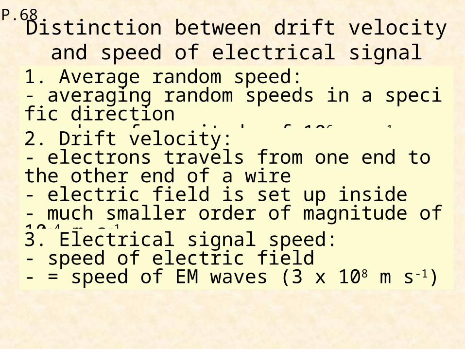
P.68Distinction between drift velocity and speed of
electrical signal1. Average random speed:- averaging random speeds in a specific direction- order of magnitude of 106 m s-1
2. Drift velocity:- electrons travels from one end to the other end of a wire- electric field is set up inside- much smaller order of magnitude of 10-4 m s-1
3. Electrical signal speed:- speed of electric field- = speed of EM waves (3 x 10⁸ m s-1)

P.68
Average random speed
Drift velocity
Electrical signal speed
Carrier Electrons Electrons Electric field
Condition
No current
flow
Current flows
Current flows
Order of magnitude / m s-
1
106 10-4 108

P.68
nqvA
I
nQvvQnA
I422
nQvvQnA
I1010
nQvvQnA
I33

P.69
Mass of 1 mole = 64 g = 0.064 kg
No. of mole in 1 m3 = 9000 / 0.064 = 140625
No. of atom in 1 m3 = 140625 (6x10²³) = 8.4375 x 1028
No. of free e- in 1 m3 = n = 8.4375 x 1028

P.69
Conduction electrons collide the lattice ions only due to higher chance.
P.69
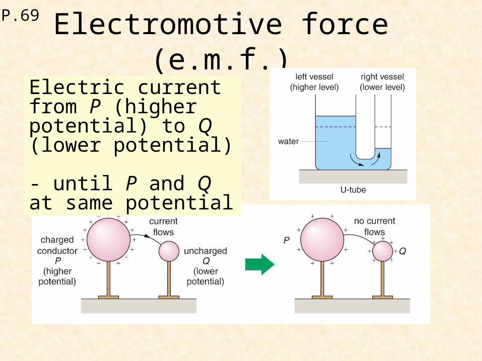
Electromotive force (e.m.f.)
Electric current from P (higher potential) to Q (lower potential) - until P and Q at same potential

P.69
Electromotive force (e.m.f.)
The electromotive force (e.m.f.) of a source is defined as the electrical potential energy supplied to each coulomb of charge by the source to drive the charge around a complete circuit.
charge
suppliedenergy source a of e.m.f.
Unit: volt (1 V = 1 J C-1)

P.69
Potential difference (p.d.)
The potential difference (p.d.) between two points in a circuit is the energy converted from electrical potential energy to other forms when one coulomb of charge passing between the points outside the power source.
Unit: J C-1 or volt (V)
P.69
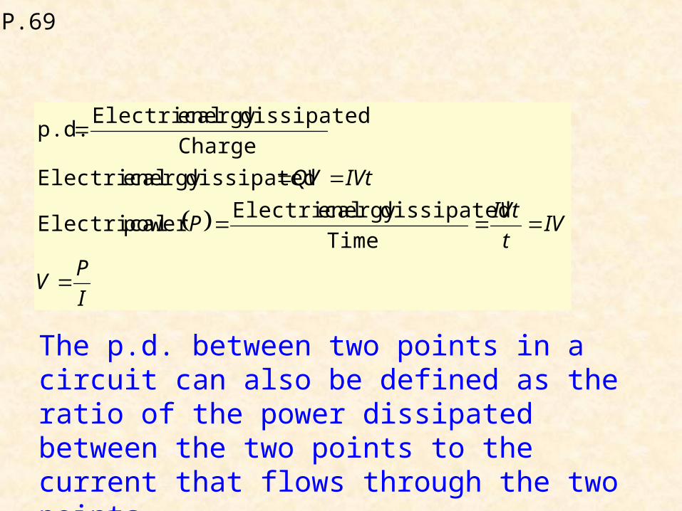
The p.d. between two points in a circuit can also be defined as the ratio of the power dissipated between the two points to the current that flows through the two points.
I
PV
IVt
IVtP
IVtQV
Time
dissipatedenergy Electricalpower Electrical
dissipatedenergy Electrical
Charge
dissipatedenergy Electricalp.d.

P.69
Potential difference (p.d.)
Q
EV
QVE
p.d. Charge Energy
I
PV
IVP
p.d.Current Power
1. Definition of volt (1 V)- 1 J of electrical energy is converted to other forms of energy between two points when 1 C of charge flows- power dissipated between two points is 1 W when current flowing is 1 A

P.69
Potential difference (p.d.)
2. Measurement of p.d.:- voltmeter is connected across two points

P.70
Combination of cells
1. In series
= 1 + 2 + 3
2. In parallel
the equivalent e.m.f. of the system is equal any one of the e.m.f. of cells.
= Max(1 , 2 , 3 )

P.70
Electrical resistance1. Definition of resistance- unit: ohm ()
I
VR )( Resistance
The ohm (1 Ω) is the resistance of a conductor when a current of one ampere (1 A) flows through the conductor, the potential difference across it is one volt (1 V).

P.70
Current – voltage relation

P.70
Ohm’s LawOhm’s Law states that the steady current through a metallic conductor is directly proportional to the potential difference across it, provided that the temperature and other physical conditions remain constant.
Ohmic conductor- conductor obeys Ohm’s Law (I p.d.)
P.70Non-ohmic conductor- I-V characteristics are not straight lines
Notes:
1. The expression V/I = R is not a representation of Ohm’s Law but a representation of the resistance R. A non-ohmic conductor also has a resistance which can be found using the equation R = V/I but its value is not a constant.
2. Ohm’s Law can be represented by the expression V/I = constant only when the temperature is constant. This implies that at constant temperature, the resistance of an ohmic conductor is independent of the current I or the potential difference V.
3. Therefore, Ohm’s Law is only a special case of resistance behaviour.

P.70

P.72 Combination of resistorsResistors in seriesIn series
321
321321 ,
RRRI
V
IRIRIRVVVVV
For the resistors connected in series, the equivalent resistance (R) is:
...221 RRRR

P.72 Combination of resistorsResistors in parallel
In parallel1. Equivalent resistance
321
33
22
11321
111
,,,
RRRV
R
V
R
VI
R
VI
R
VIIIII
For the resistors connected in parallel, the equivalent resistance (R) is:

P.72
Resistors in parallelNotes: For resistors joined in parallel, the equivalent resistance is always less than the resistance of any one of the resistors.
2. Currents in resistors
currentMain sresistance of Sum
resistanceother The
sresistance of Sum
sresistance ofProduct
21
21
21
2111
21
21
IRR
RI
RR
RRIIRRI
RR
RRR
P.72
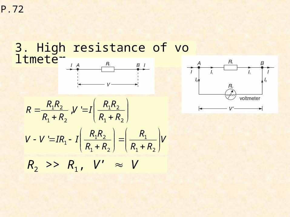
3. High resistance of voltmeter
VRR
R
RR
RRIIRVV
RR
RRIV
RR
RRR
21
1
21
211
21
21
21
21
'
',
R2 >> R1, V’ V

P.72
Combination of resistors
http://lectureonline.cl.msu.edu/%7Emmp/kap20/RR506a.htm

P.73
Factors affecting resistance of a conductorFactors affecting resistance of a conductor
Physical dimensionPhysical dimension
MaterialMaterial
Effect of temperature on Effect of temperature on resistanceresistance

P.73
Physical dimension
AR
)( Resistance

P.73
Material
Different materials have different conducting properties
AR
- resistivity =
unit: m RA

P.73
Material ResistivitySilver 1.62x10⁻⁸Copper 1.69x10⁻⁸
Tungsten 5.25x10⁻⁸Platinum 1.06x10⁻⁸
Silicon-pure 2.5x10³n-type 8.7x10⁻⁴p-type 2.8x10⁻³
P.73
Effect of temperature on resistance
1. Effect on conductors- In solids, atoms vibrate about their equilibrium positions- temperature increases, amplitude of vibration larger- chance of collision with free electrons higher- resistance higher- current lower
P.73
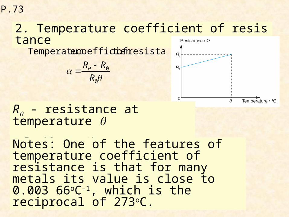
2. Temperature coefficient of resistance
0
0
resistance oft coefficien eTemperatur
R
RR
R - resistance at temperature
= R0 (1 + )Notes: One of the features of temperature coefficient of resistance is that for many metals its value is close to 0.003 66oC–1, which is the reciprocal of 273oC.

P.73
r
VI
r = internal resistance of the cell
Internal resistance of a cell and terminal voltage

P.73
Internal resistance of a cell and terminal voltage
Determining internal resistance of a cell
terminal voltage- voltage across the terminals of a cell
ε = V + IrV= (-r) I + ε
Slope = -r

P.74
73 Ω
Resistance Box

P.74
Potential Divider
R2
R1
A
C
21
0
RR
VI
Vo
Vout
021
111 V
RR
RIRVVout

P.74
Effect of external load (RL) on output p.d.
1L1
L1E
L1E
111
RRR
RRR
RRR
If RL >> R1, RE = R1
V’ = voltage across R1
1. Rheostat – provide continuously variable p.d. from 0 to full voltage of supply V

P.74
2. Thermistor – resistance decreases with increase in temperature
VRR
RV
21
1' VRR
RV
21
2'

P.75
321
1111
RRRR
(1)
F
T
T
U = QV In parallel connection, p.d. are the same
Q are the same, so U are the same.
(2)
2
11
RR RR 2
(3)
32
111
RRRnew
R
1 RRnew

P.75
)(26)42(
2VVVV PGGP
Switch S is open
Consider the division of voltageGK
)(2 VVP
Switch S is closed
Consider the division of voltage
)(36)
)44()4)(4(
2(
2VVVV PGGP
)(3 VVP
P.75
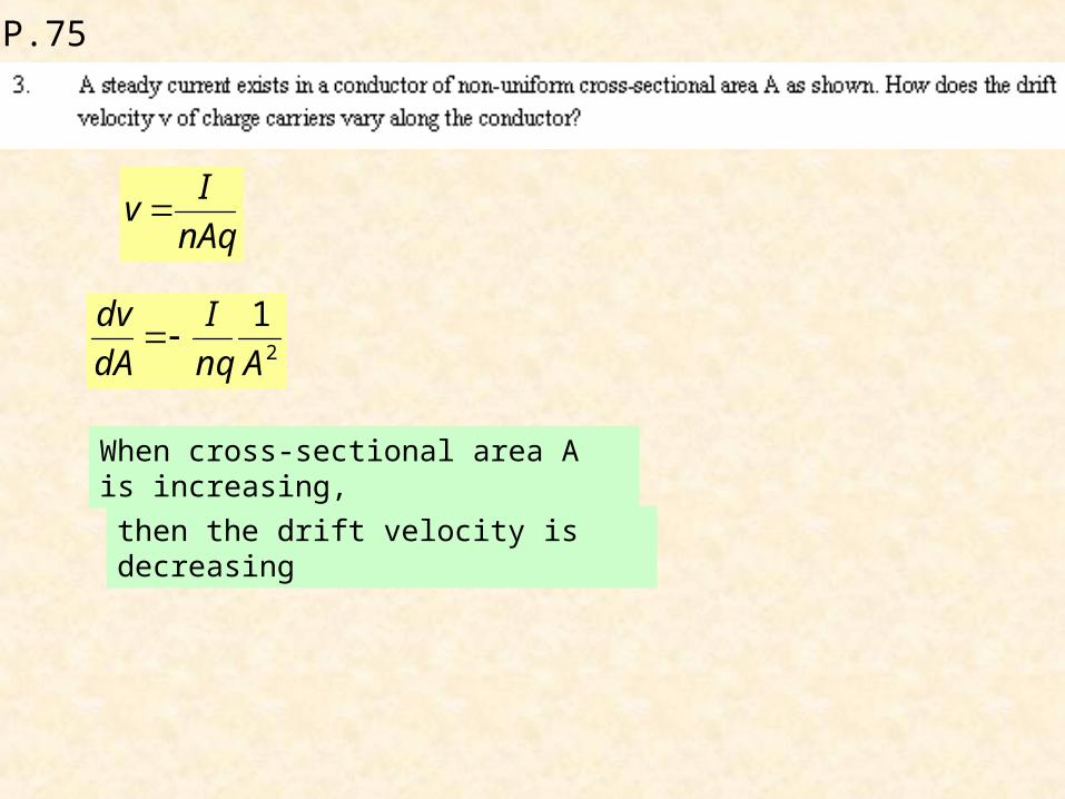
nAq
Iv
2
1
Anq
I
dA
dv
When cross-sectional area A is increasing,
then the drift velocity is decreasing
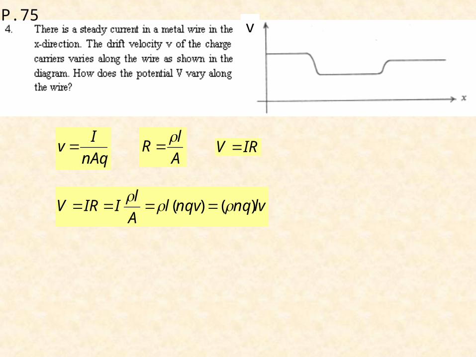
P.75v
nAq
Iv
A
lR
IRV
lvnqnqvlA
lIIRV )()(

P.75
R1 = V / I = 1 Ω R2 = V / I = 2 / 5 = 0.4 Ω
ΔR = R2 - R1 = 0.4 – 1 = - 0.6 Ω

P.76
Maximum power
rR
rR
rRRErRE
dR
dP
RrR
EIVP
rR
EI
)(
20
power) maximum(For
,
4
222
2

P.76
Efficiency
rRI
RI
2
2
inputPower
outputPower
%100
rR
R
For maximum power outputR = r, = 50%

P.77
For running motor, back emf εwill be induced
T
T
T
V – ε= I R
I V – Iε= I2 R = power dissipated as heat
P.78
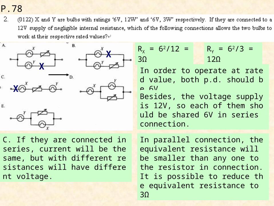
RX = 62/12 = 3Ω RY = 62/3 = 12Ω
In order to operate at rated value, both p.d. should be 6V.
Besides, the voltage supply is 12V, so each of them should be shared 6V in series connection.
XX
C. If they are connected in series, current will be the same, but with different resistances will have different voltage.
X
In parallel connection, the equivalent resistance will be smaller than any one to the resistor in connection. It is possible to reduce the equivalent resistance to 3Ω

P.78
The bulbs are non-ohmic
Total p.d. of bulbs are 200 V
The current flowing through bulbs are 0.24 A
For X, I = 0.24 A and V = 50 V
PX = (0.24)(50) = 12 (W)
For Y, I = 0.24 A and V = 150 V
PX = (0.24)(150) = 36 (W)

P.78
Lx = 3 Ly
A
lR
mx = my
Ax Lx = Ay Ly
3 Ax = Ay
x
xx A
LR
y
yy A
LR
1
9)3)(3(
xy
yx
y
x
AL
AL
R
R
P = I2 R
4
9
)2(
)1(2
2
y
x
y
x
R
R
P
P

P.78
At y-intercept, R=0)( ArrRI
)5.0(5.1 rIIR
5.1
)5.0(
5.1
11 r
RI
5.1
)5.0(88.0
r
)(82.0 r

P.78
(1) The glass wall of bulb ONLY absorb heat released by the filament, brightness is NOT affected.
F
F
T
(2) Power taken by filament should be dominated by the very large resistance of filament, thus less energy is lost in other part of the circuit.
(3) The filament emits visible light only when it is very hot. Most of them are infra-red radiation.

P.79
In parallel connection, p.d. is the same.R
VP
2
3
1
3
2
2
3 P
P
R
R R2 = 3 R3
Equivalent resistance in parallel connection
332
3223 4
3R
RR
RRR
12
1 RIP
)3()3
()( 32
33
32
2
32
32 RI
RR
RRI
RR
RP
32
2 16
3RIP P1 = P2
12
32
2 16
3RIRIP
31 16
3RR

P.79
When switch S is closed, the equivalent resistance across R1 and R2 will be reduced.
More p.d. across R3.Potential at point Q will be more negative.
G
Potential at point P will be less positive.

P.79
(1) If r > R, then greater p.d. across r than R.
T
T
T
The terminal p.d. (ε – I r) = I R will be small.
Power loss I2 r of the battery will be greater.
(2) If R > r, VR will be greater. Power loss I2 R of the resistor will be greater.
(3) If R = r, Power supplied by battery will be maximum.

P.79
)(
2
rR
VP

P.80
For maximum power dissipated,
Total external R = internal resistance r
R + 6 = r
It is impossible to have solution
R= 0 can have larger power consumption

P.80

P.80

P.80

P.80

P.80

P.81

P.81
P.81
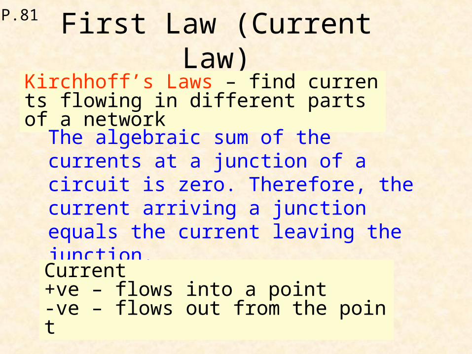
First Law (Current Law)Kirchhoff’s Laws – find currents flowing in different parts of a network
The algebraic sum of the currents at a junction of a circuit is zero. Therefore, the current arriving a junction equals the current leaving the junction.i.e. ΣI = 0
Current+ve – flows into a point-ve – flows out from the point
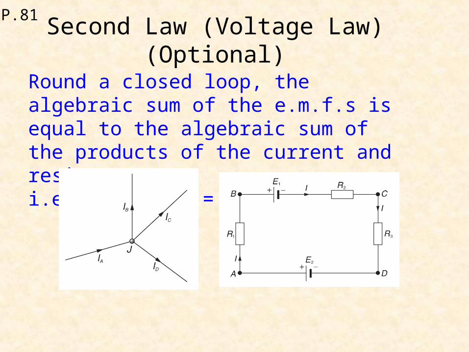
P.81Second Law (Voltage Law)
(Optional)Round a closed loop, the algebraic sum of the e.m.f.s is equal to the algebraic sum of the products of the current and resistance.i.e. ΣE = Σ (IR)

P.81
Vx is equal to e.m.f. 2V
2)6(105
5
kk
kVX
X
No voltmeter reading

P.82
VA – VC = (0.1)(1) = 0.1
0.1A
A
B
C
VA – VB = (0.2)(5) = 1
If VC > VB , current flows from C to B.
I1
VC - VB = I1 (3)
(VA - 0.1) – (VA – 1) = I1(3)
I1 = 0.3
I2
By Kirchhoff’s 1st law,
I2 = I1 – (0.1)
I2 = 0.2 (A)

P.82
By Kirchhoff’s Law
rI AC
4
A B
C
D
549 CDV
rICD
5
CDBCAC III
rI
r BC
54
rIBC
1
1 rIV BCBC
651 CBCB VVV
369 BAAB VVV
P.82
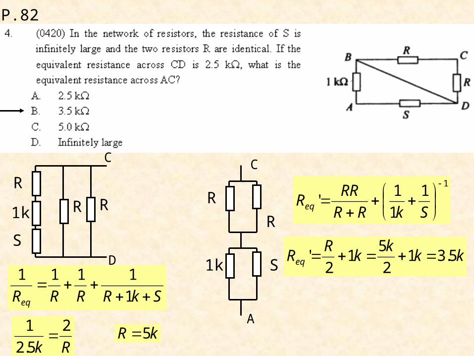
SkRRRReq
1
1111
C
D
RR
R
1k
S
Rk
2
5.2
1 kR 5
C
A
R
R
1k S
11
1
1'
SkRR
RRReq
kkk
kR
Req 5.312
51
2'
P.83
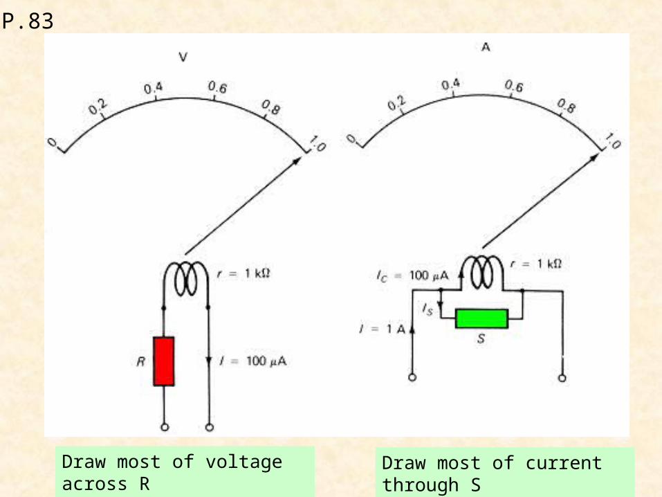
Draw most of voltage across R Draw most of current through S

P.83Conversion to ammeter
Limit f.s.d. current
Connect a small resistor (shunt) in parallel to draw majority of current
In ideal case, internal resistance of ammeter is zero.

P.84Conversion to voltmeter
Limit f.s.d. voltage
Connect a large resistor (multiplier M) in series to share majority of p.d.
In ideal case, internal resistance of voltmeter is infinite.

P.84
For 10A mode
9.9A
(9.9) R1 = (0.1) (10+R2)
0.1A
0.1A
For 1A mode
(0.9) (R1 +R2) = (0.1) (10)
0.9A 0.9A
0.1A
Solve it
(0.9) (R1 +R2) = (0.1) (10)
19.9
)10(1.09.09.0 2
2
R
R
111.019.9 22 RR
12 R
(0.9) (R1 +1) = 1
R1 = 1/9

P.84
For this conversion, a multiplier (high resistance) should be connected in series with the galvanometer to share most of the input voltage.
5 = (100μ)(1k + RM)
5 = (100μ)(Rtotal)
Rtotal= 50 kΩ
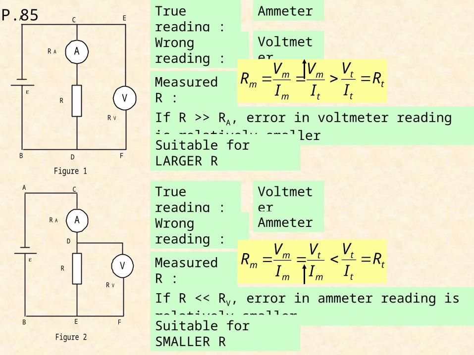
P.85 True reading :
If R >> RA, error in voltmeter reading is relatively smaller
RA
R
A C E
B D F
A
V
RV
Figure 1
RA
R
A C
EB
D
F
A
V
RV
Figure 2
Ammeter
Wrong reading : Voltmeter
Measured R :t
m
m
mm I
V
I
VR t
t
t RI
V
Suitable for LARGER R
True reading :
If R << RV, error in ammeter reading is relatively smaller
Voltmeter
Wrong reading : Ammeter
Measured R :m
t
m
mm I
V
I
VR t
t
t RI
V
Suitable for SMALLER R

P.86As Voltmeter

P.86As Ammeter

P.86As Ohmmeter

P.86
S is open
2
RR
RVV R
By division of voltage
A
C
R
S R
V
ε
A
C
R
S R
V
ε
S is closed
R is shorted
V’ = ε
P.86
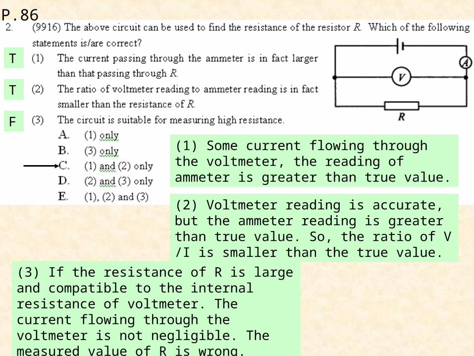
(1) Some current flowing through the voltmeter, the reading of ammeter is greater than true value.
T
T
F
(2) Voltmeter reading is accurate, but the ammeter reading is greater than true value. So, the ratio of V /I is smaller than the true value.
(3) If the resistance of R is large and compatible to the internal resistance of voltmeter. The current flowing through the voltmeter is not negligible. The measured value of R is wrong.

By division of voltage,
P.87
60 Ω resistors are neglected.
1010
R
RVR
V
10020
80
R
R 80R
10 Ω resistors are neglected.
6060
R
RVR
V
10012080
80
RV 40RV
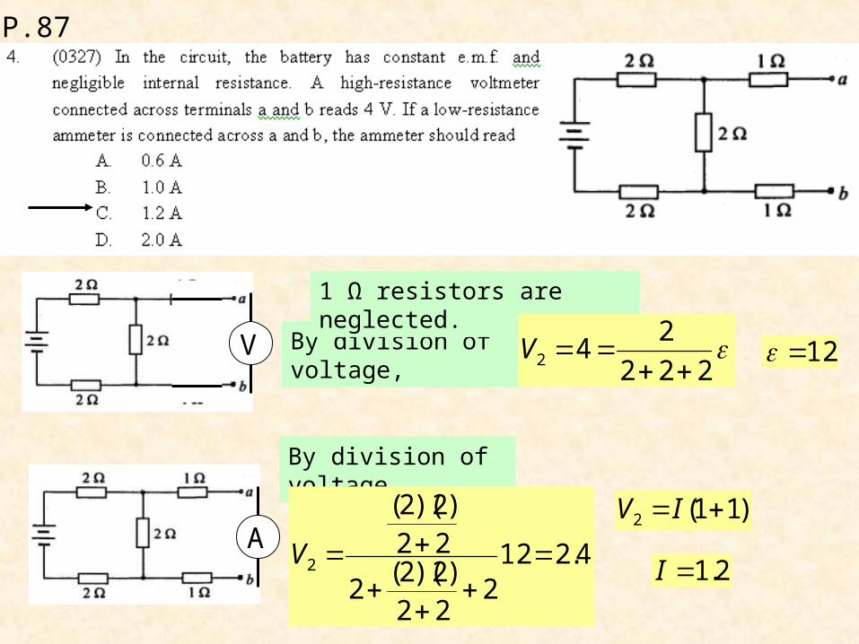
P.87
V By division of voltage,
1 Ω resistors are neglected.
222
242 V 12
A
By division of voltage,
4.2122
22)2)(2(
2
22)2)(2(
2
V
)11(2 IV
2.1I
P.87

P.87

P.87

P.88

P.87

P.87

P.88 Wheatstone Bridge
If P, Q, R are given,
Put S into the circuit and the switch is closed
If the reading of galvanometer is ZERO,
It means that VB = VD
By division of voltage,
Voltage ratio in ABC = Voltage ratio in ADC
S
R
Q
P
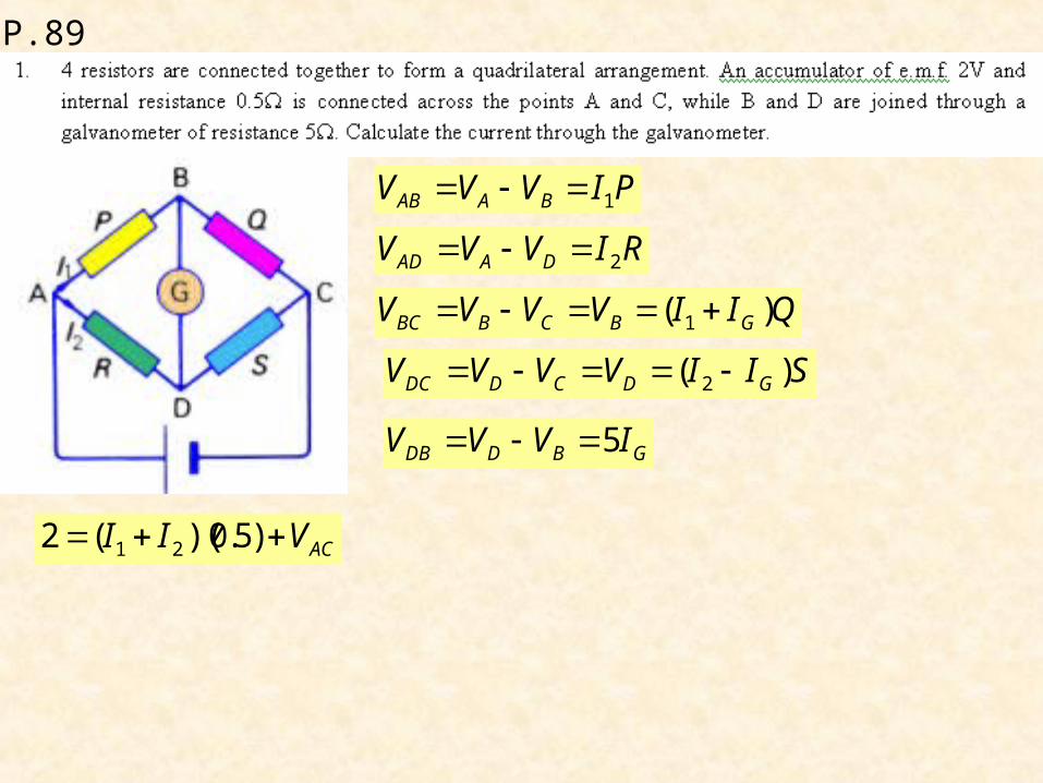
P.89
ACVII )5.0)((2 21
PIVVV BAAB 1
RIVVV DAAD 2
QIIVVVV GBCBBC )( 1
SIIVVVV GDCDDC )( 2
GBDDB IVVV 5

P.89
At steady state, the capacitor is fully chargedVC = VB – VA
No current flowing through capacitor
By division of voltage,
2636
32
VVA
4621
24
VVB
Q = C(VB – VA)
Q = (20x10-6)(4 – 2)
Q = 40x10-6
QA = -40x10-6
Lower in potential

P.89 Metre Bridge
Metre bridge – simple form of Wheatstone bridge

P.89 Metre Bridge
If the reading of galvanometer is ZERO,
S
R
Q
P

P.90
When the bridge is balanced,
r
r
Q
P
S
R
2
1
Notes: When using the metre bridge, certain precautions need to be taken.
1. The value of the standard resistance S need to be chosen such that the balance point B is about in the middle third of the slide wire, i.e. roughly between the 30 cm mark and the 70 cm mark. This is done by trial and error. When the balance point falls in the middle third of the wire, the percentage errors in the measurement of l1 and l2 are of the same order.
2
1
S
R

P.90
Notes:
2. The slider should not be slided on the slide wire so that its uniformity is maintained.
3. The experiment must be repeated with the unknown resistance R in the right-hand gap and the standard resistance S in the left-hand gap. This is to eliminate end errors. A source of end error is the point where the slide wire is soldered to the copper strips. The different amounts of solder used may result in the points of contact having different electrical resistances.
Metre bridge – not suitable for low resistance
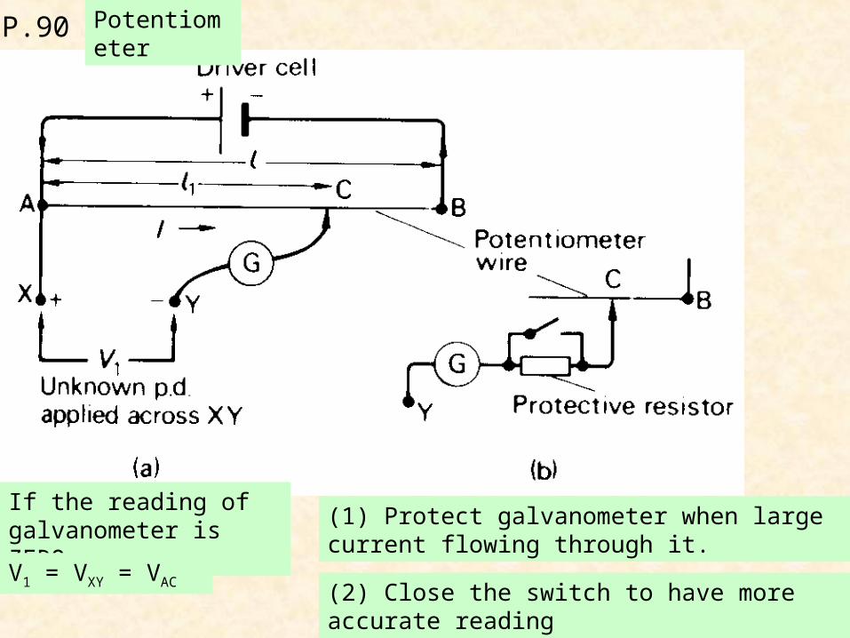
P.90 Potentiometer
If the reading of galvanometer is ZERO,
V1 = VXY = VAC
(1) Protect galvanometer when large current flowing through it.
(2) Close the switch to have more accurate reading

P.91 Measurement of p.d.
l
l
V
V 11
If the slider moves towards point B,
Potential at point C < Potential at point Y
Current flows from point Y to point C

P.92 Calibrating a voltmeter
Read the reading of point C
l
lV 1
Voltmeter reading should be the same, otherwise
Adjust the value of rheostat until the reading of galvanometer is zero

P.93 Calibrating an ammeter
Read the reading of point C
l
lV 1
Ammeter reading should be the same, otherwise
Adjust the value of rheostat until the reading of galvanometer is zero
R
VI

P.93 Measurement of internal resistance of a cell
Read the reading of point C when the switch is open.
VL
l0
V = e.m.f. of cell
Internal resistance r is useless because
No current flowing through cell and r
Read the reading of point C when the switch is closed.
VL
lIRIr
0l
lIr
)( rRI
0l
l
rR
R
00
111
lRl
r
l
Plot a graph of (1/l) against (1/R)

P.93 Measurement of internal resistance of a cell
R
rR
r
10,01
When
10
rR
11
intercept on 1/R- axis

P.94

P.94

P.94

P.94