Embed Size (px)
Citation preview

produced by: glitchscience.com 2011©
2014©
1
AKAI S950
Replacement Display
Install Guide
glitchscience.com

produced by: glitchscience.com 2011©
2014©
2
Table of Contents_________________ Required Tools.......................................... p. 3
Installation ................................................ p. 4 - 18
Opening the Case................................. p. 4 - 8
Removing the old LCD ......................... p. 9 - 12
Installing new LCD ............................... p.13 - 17
Testing the LCD / Finishing.................. p.18
Read the entire document before beginning the installation process.
************************************************** Be sure to unplug the machine before
working on the inside, the voltages inside have the potential to be very dangerous!
**************************************************

produced by: glitchscience.com 2011©
2014©
3
Fig. 1 - Phillips Head Screwdriver
Required Tools:
Phillips Head Screwdriver

produced by: glitchscience.com 2011©
2014©
4
Fig. 2 - Screw locations on the sides of the case
Opening the case:
Remove the screws from the left and right sides of the case. There are 6
screws on each side that need to be removed, 12 in total.

produced by: glitchscience.com 2011©
2014©
5
Fig. 3 - Screw location on the back of the case
Opening the case:
Remove the screw from the back of the case. There is only 1 screw on the
back of the case that needs to be removed.

produced by: glitchscience.com 2011©
2014©
6
Fig. 4 - Screw locations on the bottom of the case
Opening the case:
Remove the screws from the bottom of the case. There are only 3 screws
on the bottom of the case that need to be removed.

produced by: glitchscience.com 2011©
2014©
7
Fig. 5 - Screw locations on the top inside of the case
Opening the case:
Remove the top cover from the case.
Remove the screws from the top inside of the case. There are only 3
screws on the top inside of the case that need to be removed.

produced by: glitchscience.com 2011©
2014©
8
Fig. 6 - These knobs need removed
Opening the case:
The front face of the case needs to be removed.
Now that the screws have been taken out, the 3 knobs marked in the photo
above need to be removed. Just pull on them and they will come off.
Once the knobs have been taken off, remove the front face panel.
produced by: glitchscience.com 2011©
2014©
9
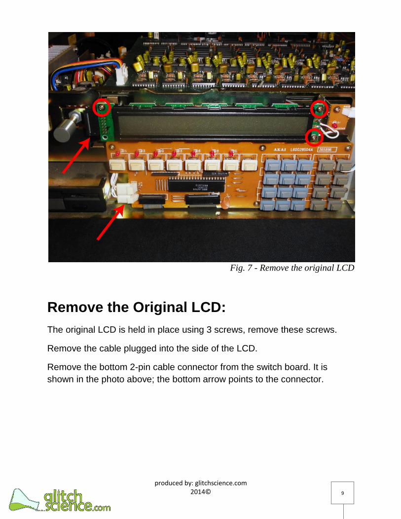
Fig. 7 - Remove the original LCD
Remove the Original LCD:
The original LCD is held in place using 3 screws, remove these screws.
Remove the cable plugged into the side of the LCD.
Remove the bottom 2-pin cable connector from the switch board. It is
shown in the photo above; the bottom arrow points to the connector.

produced by: glitchscience.com 2011©
2014©
10
Fig. 8 - Unscrew the LCD inverter
Remove the Original LCD:
The original LCD backlight has an inverter it is connected to. The inverter is
located behind the LCD and is held in place by 2 screws.
Remove the 2 screws holding the inverter in place.
If you want to remove the LCD without cutting the wiring, remove the two
screws shown in the red rectangle in the photo above. Then push the LCD
through the hole as shown in the photos on the next two pages in Figures 9
through 11. Figure 12 shows the original LCD and inverter board
completely removed, no wires needed to be cut.

produced by: glitchscience.com 2011©
2014©
11
Fig. 9 - Pull LCD through the hole pointed to
Fig. 10 - Pull LCD through the hole

produced by: glitchscience.com 2011©
2014©
12
Fig. 11 - Pull LCD through the hole
Fig. 12 - Original LCD and inverter removed
produced by: glitchscience.com 2011©
2014©
13
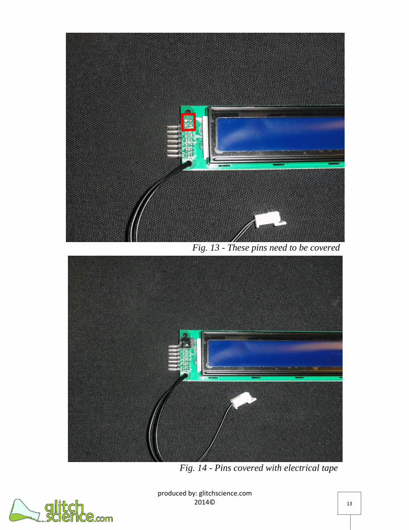
Fig. 13 - These pins need to be covered
Fig. 14 - Pins covered with electrical tape

produced by: glitchscience.com 2011©
2014©
14
Fig. 15 - LCD must be placed behind mounting frame
Fig. 16 -Screw top 2 screws from the backside

produced by: glitchscience.com 2011©
2014©
15
Fig. 17 - Top screw screwed in from the back
Fig. 18 - Top screw screwed in from the back

produced by: glitchscience.com 2011©
2014©
16
Fig. 19 - Plug in the power cable
Fig. 20 - Replacement LCD installed

produced by: glitchscience.com 2011©
2014©
17
Install the Replacement LCD:
Once the original LCD is completely removed, the replacement can be
installed in its place.
Since there is a slight difference in the depth of the LCD dimensions, the
LCD must be mounted differently than the original. Also, the top 4 pins on
the LCD must be covered in order to prevent them from shorting on the
metal mounting frame. Figure 13 indicates the pins which must be covered
and Figure 14 shows those pins covered with electrical tape.
In order to account for the difference in depth the replacement LCD must
be placed behind the mounting frame as shown in Figure 15. The top 2
screws must be screwed in from the backside as shown in Figure 16, 17
and 18. The bottom right screw can be screwed in from the front as shown
in Figure 17.
Once the replacement LCD is mounted in place, plug the cables in, as
shown in Figures 18, 19, and 20.

produced by: glitchscience.com 2011©
2014©
18
Fig. 21 - Testing the LCD
Test the LCD:
Now that the replacement LCD is mounted and plugged in, it is possible to
test the LCD to make sure it is properly installed and working before closing
the unit up.
Since the case is opened be sure to be cautious and avoid touching the
insides of the unit when it is powered up, this may result in a shock or
worse.
To test the LCD, plug the unit up and power it on, the LCD should light up
and display characters. The LCD contrast can be adjusted as needed by
turning the contrast knob.
Once the LCD is verified working, the installation is complete. Power off the
unit and unplug it, then screw it all back together. Install completed.

produced by: glitchscience.com 2011©
2014©
19
This guide is not to be distributed or redistributed without explicit permission from the owner of the document. contact: glitchscience[at]gmail[dot]com with inquiries


![PSR-S950/S750 Reference Manual - Home - Yamaha ... PSR-S950/S750 Reference Manual Panel Button Chart ( [CHANNEL ON/OFF] CHANNEL ON/OFF display SONG — 2 STYLE 1/2 or 2/2 (PSR-S950)](https://img.dokumen.tips/doc/110x75/5ad09e167f8b9ad24f8de05a/psr-s950s750-reference-manual-home-yamaha-psr-s950s750-reference-manual.jpg)

![Akai Pdp4206em1 [Sm]](https://img.dokumen.tips/doc/110x75/563db8fc550346aa9a98e1cb/akai-pdp4206em1-sm.jpg)


![Akai Pdp4216m [Sm]](https://img.dokumen.tips/doc/110x75/563db8f1550346aa9a986e75/akai-pdp4216m-sm.jpg)