Embed Size (px)
Citation preview
User Guide
AK-System Manager AK-SM 800 Series
ADAP-KOOL® Refrigeration Control System
www.danfoss.com
User Guide | AK-System Manager, AK-SM 800 Series
2 | BC316842192932en-001001 © Danfoss | DCS (vt) | 2020.03
Chapter 1: Product IntroductionProduct Introduction ....................................................................................... 3
Specifications ..................................................................................................... 4
Chapter 2: Installation and start-up configurationInstallation ........................................................................................................... 5
Connections ........................................................................................................ 7
Network topology ............................................................................................ 7
Lon RS485 Topology .............................................................................. 8
MODBUS topology ................................................................................. 9
First time startup .............................................................................................10
AK-SM 800 Host Network Configuration ................................................10
Connecting to AK-SM 810 ............................................................................12
Initial Configuration - language.................................................................13
Remote Management Tool (RMT) .............................................................14
System Upload / Download ........................................................................15
Device Management
(Configuration/System/Device Management) .....................................16
IP Configuration and suggested security settings ............................. 17
Chapter 3: Navigation and useGeneral navigation, operation and use (via web) ...............................19
Connecting to your AK-SM ..........................................................................19
Dashboard view ...............................................................................................19
File.........................................................................................................................20
Auto History Log Collection ........................................................................23
Auto Alarm Log Collection ..........................................................................24
Managing alarms .............................................................................................25
Device detail .....................................................................................................26
System view ......................................................................................................27
Schedule view ..................................................................................................28
History (Logs) ....................................................................................................29
Collecting and viewing history ..................................................................30
Chapter 4: ConfigurationInitial Configuration - Web Wizard ...........................................................32
Copy Wizard ......................................................................................................35
Network Nodes ................................................................................................36
System configuration (Time settings / preferences) ..........................37
Communication ...............................................................................................40
Alarms..................................................................................................................40
Control tab .........................................................................................................47
Chapter 5: Master Control FunctionsRail Heat ..............................................................................................................53
Schedules ...........................................................................................................56
Customized control ........................................................................................59
Suction Pressure Optimization ..................................................................60
Adaptive Liquid Management ...................................................................62
AKC ON (Evap shutdown when injection off) ......................................63
Coordinated Adaptive Defrost ..................................................................64
Chapter 6: Advanced features and configurationsManagers Override .........................................................................................65
Light .....................................................................................................................66
Lighting Configuration .................................................................................66
Dimming control via AK I/O ........................................................................69
HVAC Configuration .......................................................................................71
Miscellaneous Configuration ......................................................................74
Energy .................................................................................................................87
Energy Configuration ....................................................................................87
Energy Measurement / Load shed ............................................................91
Detail Energy ...............................................................................................93
Enterprise Load Shed (via Danfoss EDS Service) .................................94
Demand Limiting ............................................................................................95
Boolean Logic / Calculations ......................................................................96
Chapter 7: Device supportDanfoss AKC Support (Via AK-PI 200) ......................................................98
Service Tool Support....................................................................................102
CoreSense™ (MODBUS) Support ............................................................ 103
AK-SM 800 Device support guidelines ................................................. 104
Chapter 8: MiscellaneousRecommended method for upgrading your
AK-SM 800 series front end ...................................................................... 105
Ordering .......................................................................................................... 108
Document History ....................................................................................... 108
Glossary of terms .......................................................................................... 109
Contents
User Guide | AK-System Manager, AK-SM 800 Series
© Danfoss | DCS (vt) | 2020.03 BC316842192932en-001001 | 3
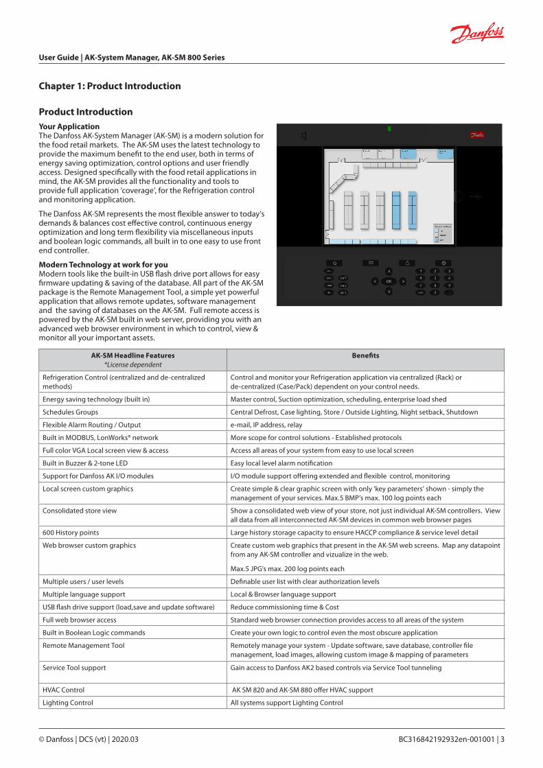
Your ApplicationThe Danfoss AK-System Manager (AK-SM) is a modern solution for the food retail markets. The AK-SM uses the latest technology to provide the maximum benefit to the end user, both in terms of energy saving optimization, control options and user friendly access. Designed specifically with the food retail applications in mind, the AK-SM provides all the functionality and tools to provide full application ‘coverage’, for the Refrigeration control and monitoring application.
The Danfoss AK-SM represents the most flexible answer to today’s demands & balances cost effective control, continuous energy optimization and long term flexibility via miscellaneous inputs and boolean logic commands, all built in to one easy to use front end controller.
Modern Technology at work for youModern tools like the built-in USB flash drive port allows for easy firmware updating & saving of the database. All part of the AK-SM package is the Remote Management Tool, a simple yet powerful application that allows remote updates, software management and the saving of databases on the AK-SM. Full remote access is powered by the AK-SM built in web server, providing you with an advanced web browser environment in which to control, view & monitor all your important assets.
AK-SM Headline Features*License dependent
Benefits
Refrigeration Control (centralized and de-centralized methods)
Control and monitor your Refrigeration application via centralized (Rack) or de-centralized (Case/Pack) dependent on your control needs.
Energy saving technology (built in) Master control, Suction optimization, scheduling, enterprise load shed
Schedules Groups Central Defrost, Case lighting, Store / Outside Lighting, Night setback, Shutdown
Flexible Alarm Routing / Output e-mail, IP address, relay
Built in MODBUS, LonWorks® network More scope for control solutions - Established protocols
Full color VGA Local screen view & access Access all areas of your system from easy to use local screen
Built in Buzzer & 2-tone LED Easy local level alarm notification
Support for Danfoss AK I/O modules I/O module support offering extended and flexible control, monitoring
Local screen custom graphics Create simple & clear graphic screen with only ‘key parameters’ shown - simply the management of your services. Max.5 BMP’s max. 100 log points each
Consolidated store view Show a consolidated web view of your store, not just individual AK-SM controllers. View all data from all interconnected AK-SM devices in common web browser pages
600 History points Large history storage capacity to ensure HACCP compliance & service level detail
Web browser custom graphics Create custom web graphics that present in the AK-SM web screens. Map any datapoint from any AK-SM controller and vizualize in the web.
Max.5 JPG’s max. 200 log points each
Multiple users / user levels Definable user list with clear authorization levels
Multiple language support Local & Browser language support
USB flash drive support (load,save and update software) Reduce commissioning time & Cost
Full web browser access Standard web browser connection provides access to all areas of the system
Built in Boolean Logic commands Create your own logic to control even the most obscure application
Remote Management Tool Remotely manage your system - Update software, save database, controller file management, load images, allowing custom image & mapping of parameters
Service Tool support Gain access to Danfoss AK2 based controls via Service Tool tunneling
HVAC Control AK SM 820 and AK-SM 880 offer HVAC support
Lighting Control All systems support Lighting Control
Product Introduction
Chapter 1: Product Introduction

User Guide | AK-System Manager, AK-SM 800 Series
4 | BC316842192932en-001001 © Danfoss | DCS (vt) | 2020.03
SpecificationsThe mounting location should be flat, dry and free of major vibrations. The AK-SM 800 should be mounted at eye level.
Environmental Range:Operating temperature:-10 – 55˚C (14 – 131˚F) @ 90% RH (non condensing) IP20
Electrical range: ~ 100 – 240 V AC 50/60 Hz, 12 W Built in alarm relay, Contact voltage: Up to 240 V, Load: AC-1 (Ohmic) Current rating. 5 Amp AC-15(inductive) Current rating. 3 Amp
LCDActive TFT colours (thin-film transistor), SVGA 800 x 600
SizeUnit Width 295 mm (11.6”), Unit Height 235 mm (9.3”), Unit Depth 65 mm (2.5”)Mounting holes 246 mm (9.7”) WidthMounting holes 175 mm (6.9”) Height
Approvals:
Declaration of conformity info- Regulation 2005/37/EC- EN 12830, 07-1999- EN 13485, 11-2001- HACCP 080R1215- CE 080R1213- C-Tick 080R1214- UL E31024
65
USB Access door Active USB Flash drive (use for load/save database and AK-SM software) User Authorization required’
Not currently Used
WARNING: To avoid risk of injury from electric shock, ensure correct electrical isolation is made before working within the enclosure.

User Guide | AK-System Manager, AK-SM 800 Series
© Danfoss | DCS (vt) | 2020.03 BC316842192932en-001001 | 5
Tools needed1. Bubble level2. Small slotted screwdriver for connector screws3. Torx 8 screwdriver for releasing the electronic unit and for
fastening the unit when recessed mounted4. Screwdriver for fixating the AK-SM 800 5. Pen for marking the 2 lower fixation holes 6. Larger slotted screwdriver for releasing the Technician lid
Installation
Wall Mounting- box1
1. Attach screw to the wall2. Mount AK-SM 800 to the screw3. Loosen Technician lid (three sides)4. Remove Technician lid5. Level the AK-SM 800 6. If drilling is necessary, mark up 2 screws in Connector part.7. Attach the Connector part to the wall using another 2 screws
Strip the cables Strip the wires
Chapter 2: Installation and start-up configuration
Wall Mounting- wiringInsert cables through the rubber grommets
Secure wires in connectors by screwdriver
Strain relief the cables
1) For installation in countries where UL Listing is required, please refer to the installation instruction provided with the product.

User Guide | AK-System Manager, AK-SM 800 Series
6 | BC316842192932en-001001 © Danfoss | DCS (vt) | 2020.03
Carefully replace the keypad, ensure that it securely snaps into place
Wall Mounting- Panel recessedFrom the front:A hole of the size 280 x 220mm is machinedThe AK-SM 800 is inserted in the hole
From the backside:Slide the 3 fastener into the housing part The screws are inserted into the fastenersSecure the unit by tightening the screws
Remove Technician lidFrom the back, push cables inside the housing
Insert the plastic divider to separate and make sure firmly snaps into place.The plastic insert is provided in the accessory bag and is required for panel mounting the unit where UL Listing is required.
User Guide | AK-System Manager, AK-SM 800 Series
© Danfoss | DCS (vt) | 2020.03 BC316842192932en-001001 | 7
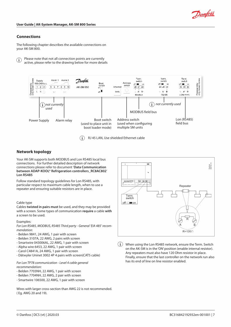
The following chapter describes the available connections on your AK-SM 800.
Please note that not all connection points are currently active, please refer to the drawing below for more details
Connections
Your AK-SM supports both MODBUS and Lon RS485 local bus connections. For further detailed description of network connections please refer to document ‘Data Communication between ADAP-KOOL® Refrigeration controllers_RC8AC802’ Lon RS485
Follow standard topology guidelines for Lon RS485, with particular respect to maximum cable length, when to use a repeater and ensuring suitable resistors are in place.
Network topology
Cable typeCables twisted in pairs must be used, and they may be provided with a screen. Some types of communication require a cable with a screen to be used.
Examples: For Lon RS485, MODBUS, RS485 Third party - General ‘EIA 485’ recom-mendation: - Belden 9841, 24 AWG, 1 pair with screen - Belden 3107A, 22 AWG, 2 pairs with screen - Smartwire 043006AL, 22 AWG, 1 pair with screen - Alpha wire 6453, 22 AWG, 1 pair with screen - Carol C4841A, 24 AWG, 1 pair with screen - Dätwyler Uninet 3002 4P 4 pairs with screen(CAT5 cable)
For Lon TP78 communication - Level 4 cable general recommendation: - Belden 7703NH, 22 AWG, 1 pair with screen - Belden 7704NH, 22 AWG, 2 pair with screen - Smartwire 106500, 22 AWG, 1 pair with screen Wires with larger cross-section than AWG 22 is not recommended. ( Eg. AWG 20 and 19).
When using the Lon RS485 network, ensure the Term. Switch on the AK-SM is in the ‘ON’ position (enable internal resistor). Any repeaters must also have 120 Ohm resistor in place. Finally, ensure that the last controller on the network run also has its end of line on line resistor enabled.
Power Supply Alarm relay
not currently used not currently used
Boot switch(used to place unit in
boot loader mode)
Address switch(used when configuring multiple SM units
MODBUS field bus
Lon (RS485) field bus
RJ 45 LAN, Use shielded Ethernet cable
User Guide | AK-System Manager, AK-SM 800 Series
8 | BC316842192932en-001001 © Danfoss | DCS (vt) | 2020.03
Cable length A cable length must not exceed 1200 m (4000 foot). A repeater (Part # 084B2241 ) must be used for longer lengths.
Lon RS485 TopologyThe cable connection must be connected from controller to controller, and no branches are allowed on the cable. If the cable length exceeds 1200 m a repeater must be inserted. If the data communication cable runs through an electrically noisy environment which impairs the data signal, one or more repeaters must be added to stabilise the signal.
When configuring Lon devices on the control bus, the highest device address that can be can be used is 127 (max. 120 controller in total)
Remember to use 120 Ohm terminators on the last filed bus controller device. Note also to enable (ON) the Term. Switch, located above each network connection point on the AK-SM 800, this will enable the built in terminator(s) for each network point on the AK-SM 800.
ConductorsThe two wires are looped from device to device. There are no polarisation requirements. (On some controllers, the clamps are designated A and B. On others there is no designation. Otherwise the connections are identical.) If a screen is used, it must be connected to the system device and any repeaters. A screen must always be looped from device to device.
The screen must not be connected to anything else. (The screen is earthed inside the screen and must not be earthed in any other way.)
Mid network connectionThis example shows the AK-SM 800 series RS485 version used in the middle of a network run. In this example ensure that both ends of the controller run are fitted with 120 Ohm terminators.
Over the past several years Danfoss has offered a version of the AK-SC 255 and AK-SC 355 which has a LonWorks® option of TP78. As a physical layer of the LonWorks® protocol these older systems offered x5 network connection points. Due to the global phase out of the TP78 option by the OEM, Danfoss has made available a special order version of the AK-SM 880 (080Z4009), which will come pre-installed with a LonWorks® TP78 options card. This ‘special’ version of the AK-SM 880 is designed to support customers who wish to migrate from existing AK-SC 255 and AK-SC 355 TP78 systems. Please note that this version of the AK-SM 880 is not intended or available in Europe’ , and offers x4 TP 78 connection points.
TP 78-Version
AK-SM
RS 485
R=120 ohmR=120 ohm
AK-SM
R=120 ohm
AK-SM
R=120 ohm

User Guide | AK-System Manager, AK-SM 800 Series
© Danfoss | DCS (vt) | 2020.03 BC316842192932en-001001 | 9
MODBUS topologyThe cable must be with screen. The cable is connected from controller to controller, and no branches are allowed on the cable. If the cable length exceeds 1200 m a repeater must be inserted. If the data communication cable runs through an electrically noisy environment which impairs the data signal, one or more repeaters must be added to stabilise the signal.
‘The System Manager can be inserted in middle of network, ensure System Manager termination is OFF. Refer to Danfoss document ‘RC8AC802 Data Communication’.
When configuring MODBUS devices on the control bus, the highest device address that can be used is 199 (max. 120 controller in total)
The wires are looped from device to device. A is connected to A B is connected to B. The screen must be connected to the system device, all controller and any repeaters. A screen must always be looped from device to device. The screen must not be connected to anything else.
Be sure to configure the MODBUS repeater AKA 222 (code#084B2240) to the correct baud rate.
See notes section at the back of this guide for MODBUS device baud rate properties.
Refer to Danfoss Instructions RI8KN402 for further details on the AKA 222 repeater’
AK-SM
AK-SM
MODBUS
R=120 ohmR=120 ohm
MODBUS
User Guide | AK-System Manager, AK-SM 800 Series
10 | BC316842192932en-001001 © Danfoss | DCS (vt) | 2020.03
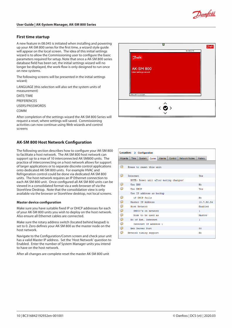
A new feature in 08.045 is initiated when installing and powering up your AK-SM 800 series for the first time, a wizard style guide will appear on the local screen. The idea of this initial settings wizard is to allow the Commissioning user to configure the basic parameters required for setup. Note that once a AK-SM 800 series database field has been set, the initial settings wizard will no longer be displayed, the work-flow is only designed to run once on new systems.
The following screens will be presented in the initial settings wizard;
LANGUAGE (this selection will also set the system units of measurement)
DATE/TIME
PREFERENCES
USERS/PASSWORDS
COMM
After completion of the settings wizard the AK-SM 800 Series will request a reset, where settings will saved. Commissioning activities can now continue using Web wizards and control screens
First time startup
The following section describes how to configure your AK-SM 800 to facilitate a host network. The AK-SM 800 host network can support up to a max of 10 interconnected AK-SM800 units. The practice of interconnecting on a host network allows for support of larger applications or to separate discrete control applications onto dedicated AK-SM 800 units. For example HVAC and Refrigeration control could be done via dedicated AK-SM 800 units. The host network requires an IP Ethernet connection to each AK-SM 800 unit. Once configured all AK-SM 800 units can be viewed in a consolidated format via a web browser of via the StoreView Desktop. Note that the consolidation view is only available via the browser or StoreView desktop, not local screens.
AK-SM 800 Host Network Configuration
Master device configuration
Make sure you have suitable fixed IP or DHCP addresses for each of your AK-SM 800 units you wish to deploy on the host network. Also ensure all Ethernet cables are connected.
Make sure the rotary address switch (located behind keypad) is set to 0. Zero defines your AK-SM 800 as the master node on the host network.
Navigate to the Configuration/Comm screen and check your unit has a valid Master IP address. Set the ‘Host Network’ question to Enabled. Enter the number of System Manager units you intend to have on the host network.
After all changes are complete reset the master AK-SM 800 unit

User Guide | AK-System Manager, AK-SM 800 Series
© Danfoss | DCS (vt) | 2020.03 BC316842192932en-001001 | 11
Slave device configuration
Make sure the rotary address switch (located behind keypad) is set to the appropriate number. For example, setting the switch to 1, will define the unit as a slave device address 1. All units in the host network must have unique host network addresses (address 0 is always master).
Once you have set the rotary address switch, reset the unit and allow the AK-SM 800 to boot up. Navigate to the Configuration/Comm screen and check your unit shows the Master IP address. Set the ‘Host Network’ question to Enabled. Enter the number of System Manager units you intend to have on the host network (matching what you have already set in the master unit)
Make sure the slave unit has a valid IP address.
To validate the host network has been correctly configured and all System Managers can see each other refer to the Master unit ‘info’ screen. Here you should see all AK-SM 800 on the host network
User Guide | AK-System Manager, AK-SM 800 Series
12 | BC316842192932en-001001 © Danfoss | DCS (vt) | 2020.03
Connecting to AK-SM 810
This section describes the steps in making an initial connection to the (screen-less) AK-SM 810 product. Once initial connectivity has been established, the system can be configured using standard workflows, as all menus, features and functions are identical to the AK-SM 820.
1. Set the rotary address switch to position 9 and power up unit. By setting address 9 the SM810 will be set to a fixed IP address of 192.168.1.161
2. Connect to the AK-SM810 via a suitable Ethernet cable to your PC, which should be running either RMT or StoreView Desktop
3. Using the address 192.168.1.161 connect to the AK-SM 810, log in using either factory set User Name and Password (Supervisor \ 12345) or what has previously been defined
4. After system configuration has been completed, it is recommended to apply a known fixed IP address in the Configuration > Comm screen. By adding a fixed IP address it will ensure subsequent connections can repeatedly be performed without issue.
5. Power Off the AK-SM 810
6. Set rotary switch to 0 (is used as Master), else set to desired slave address
7. Power unit up and validate connection by using static IP address used in the Comm screen
8. Make sure that the web port is not changed to port 1041. Doing so will render the unit unaccessible! Port 1041 is reserved for AK-ST 500 service tunnelling and does
not provide access to the web interface.
User Guide | AK-System Manager, AK-SM 800 Series
© Danfoss | DCS (vt) | 2020.03 BC316842192932en-001001 | 13
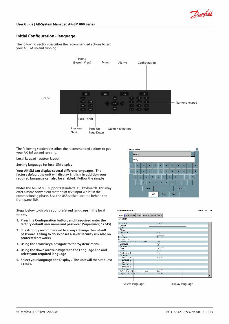
Initial Configuration - language
Home (System View) Menu Alarms Configuration
Numeric keypad
Menu Navigation
Escape
Page Up Page Down
Previous Next
Back Shift
The following section describes the recommended actions to get your AK-SM up and running.
Local keypad - button layout
Setting language for local SM display
Your AK-SM can display several different languages. The factory default the unit will display English, in addition your required language can also be enabled. Follow the simple
Steps below to display your preferred language in the local screen;
1. Press the Configuration button, and if required enter the factory default user name and password (Supervisor, 12345)
2. It is strongly recommended to always change the default password. Failing to do so poses a sever security risk also on protected networks
3. Using the arrow keys, navigate to the ‘System’ menu.
4. Using the down arrow, navigate to the Language line and select your required language
5. Select your language for ‘Display’. The unit will then request a reset.
Select language Display language
Note: The AK-SM 800 supports standard USB keyboards. This may offer a more convenient method of text input whilst in the commissioning phase. Use the USB socket (located behind the front panel lid).
The following section describes the recommended actions to get your AK-SM up and running.

User Guide | AK-System Manager, AK-SM 800 Series
14 | BC316842192932en-001001 © Danfoss | DCS (vt) | 2020.03
The Remote Management Tool (RMT) is a PC software application tool that is designed to support the AK-SM, both in commissioning and service. The RMT is a powerful tool that allows full offline programming and simulation of AK-SM databases, providing the opportunity to save considerable on site commissioning times. In addition, the RMT tool has various remote management features, facilitating complete system management. Creating custom images for the AK-SM web browser is also another function of the RMT tool. The following features can be seen in the RMT;
• Offline web Programming Launch offline web simulator(s) to allow full offline AK-SM database programming, with controller simulation you can fully pre-program your application and save the resulting database to USB for on site install.
• Program simulation From within the web browser session simulate board and point variables to test calculations and system behaviour
Remote Management Tool (RMT)
• Custom Graphics Use your own Jpeg or bitmp file to create custom images, mapped with any configured system datapoint
• File TransferFTP is not available from firmware v08.080 and later. Remotely connect, load and access system files (html web & EDF device files) Retrieve datapoints
• Address Book Save your most commonly connected site details to allow for one click connection
• Tools Download System software, backup (save) & load database files.
• Language Compatible in multi- languages
The RMT tool is available from your Danfoss sales office with associated supporting documentation.

User Guide | AK-System Manager, AK-SM 800 Series
© Danfoss | DCS (vt) | 2020.03 BC316842192932en-001001 | 15
System Upload / Download
When to use Upload / Download function.Your AK-SM 800 offers both Online and Offline configuration methods. Understanding the concept of these difference methods will help in determining the use of the Upload or Download feature.
Upload = Retrieve field bus controller device settings and sync with AK-SM 800 database
Download= Send controller device settings held in the SM800 to the field bus controller
Online Configuration: Online configuration is where the site application has live control devices (i.e. Danfoss AK-CC 550) connected to a field bus and the SM800 will be used to configure the settings and configuration of these control devices. Since the AK-SM 800 has the ability to offer online and offline programming it is important to sync the AK-SM 800 database BEFORE attempting any online configuration or setpoint changes. The UPLOAD function is used to ‘retrieve’ the control device settings and update the SM800 database. Once the upload is performed and completed any subsequent device setpoint changes done via the SM800 will get immediately sent to the field device (no need to perform upload/download)
Upload Example: A contractor arrives on site and connects the control devices to the field bus. The contractor performs a network scan to ensure all nodes on the network are present. After the network scan the contractor performs an upload function, which will sync the AK-SM 800 database with the settings that exist in the field bus control devices. The upload will take the settings from the control devices and sync to the SM800 database. Once the upload is complete the contractor can continue to configure via the AK-SM 800 and change settings in the control devices.
Offline Configuration: With the use of the RMT tool, a comprehensive AK-SM 800 offline configuration can be accomplished without even being connected to any control device or AK-SM 800. For many customers and users this represents a considerable time saving in the configuration phase (assuming the site definition is known).
By selecting the appropriate AK-SM 800 simulator in the RMT tool you can simulate (in an offline state) a AK-SM 800 installation,
complete with control device selections (known as EDF selections). The EDF device selections come pre-set with factory parameter settings. Once your application has been defined and any EDF setting changes made, the simulator (including all EDF’s) can be saved in a AK-SM 800 database format. This saved AK-SM 800 database file can then be later loaded to a live AK-SM 800 on site and all the control device settings (contained in the EDF files) can be ‘pushed down’ to the relevant connected live control devices to configure them. [Note that for some Danfoss controls the Main Switch is required to be in the off mode before settings can be written].
To ensure the original ‘offline’ AK-SM 800 database (which holds all the control EDF device settings) is in sync with the live control devices the ‘DOWNLOAD’ function is required. It is critical that the AK-SM 800 is in sync with the live control devices since the parameters in the SM800 database could be different to the parameters residing in the live control device(s). Use the Download function when you have performed an offline configuration of your application.
Download Example: A contractor opens the RMT tool and decides to fully configure the AK-SM 800 which will be used in a supermarket in the following week. He knows how many and what type of devices will be on site and decides to deploy the RMT tool to offline program the AK-SM 800 database. After selecting the device type(s), via the EDF selections the contractor decides to configure some key parameters per the customer application. Finally the AK-SM 800 database is saved to USB and the following week the contractor arrives on site. The AK-SM 800 on site is connected to all the control devices via the filed bus and a network scan is performed to check field communications is valid. The contractor loads the AK-SM 800 database and performs a DOWNLOAD function to ensure that the settings made offline now get sent to the devices on the field bus.
The Upload and Download function can be found under Configuration>Network Nodes.
Note: Due to field bus speeds, quantity of data sets and devices the Upload or Download function can take several minutes. On sites with a large number of devices Danfoss recommends selecting 30 to 40 devices at a time and repeating the procedure.
User Guide | AK-System Manager, AK-SM 800 Series
16 | BC316842192932en-001001 © Danfoss | DCS (vt) | 2020.03
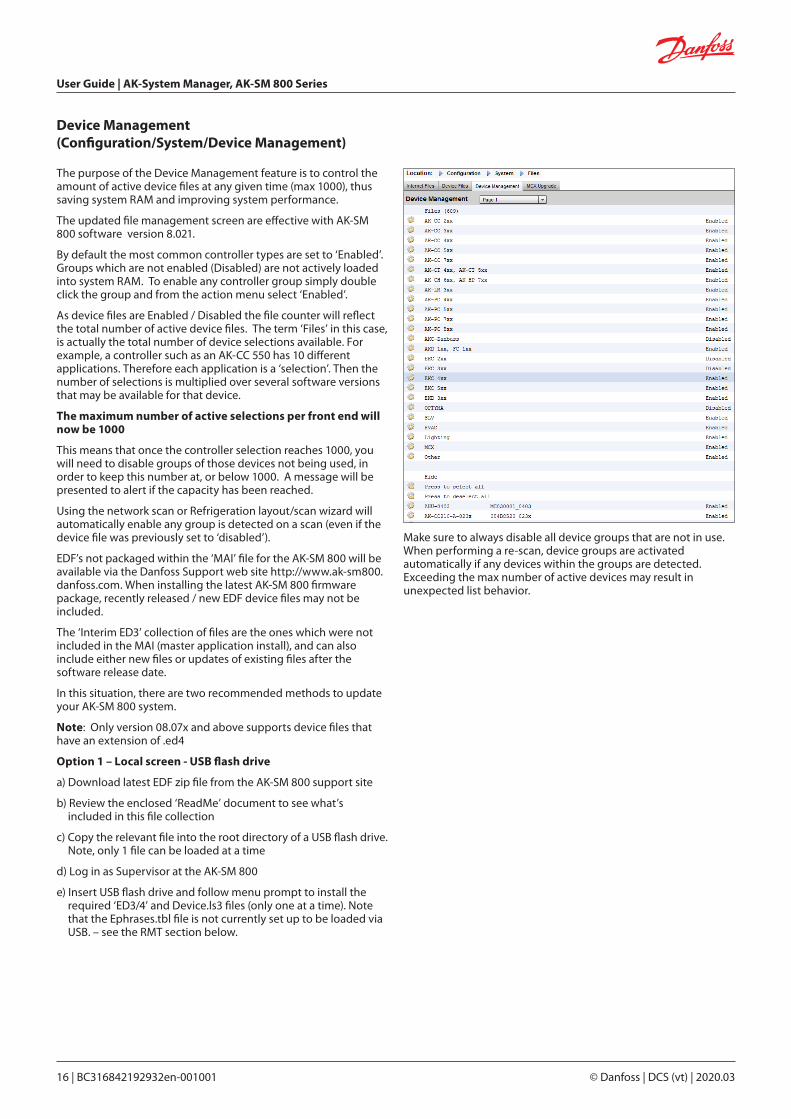
The purpose of the Device Management feature is to control the amount of active device files at any given time (max 1000), thus saving system RAM and improving system performance.
The updated file management screen are effective with AK-SM 800 software version 8.021.
By default the most common controller types are set to ‘Enabled’. Groups which are not enabled (Disabled) are not actively loaded into system RAM. To enable any controller group simply double click the group and from the action menu select ‘Enabled’.
As device files are Enabled / Disabled the file counter will reflect the total number of active device files. The term ‘Files’ in this case, is actually the total number of device selections available. For example, a controller such as an AK-CC 550 has 10 different applications. Therefore each application is a ‘selection’. Then the number of selections is multiplied over several software versions that may be available for that device.
The maximum number of active selections per front end will now be 1000
This means that once the controller selection reaches 1000, you will need to disable groups of those devices not being used, in order to keep this number at, or below 1000. A message will be presented to alert if the capacity has been reached.
Using the network scan or Refrigeration layout/scan wizard will automatically enable any group is detected on a scan (even if the device file was previously set to ‘disabled’).
EDF’s not packaged within the ‘MAI’ file for the AK-SM 800 will be available via the Danfoss Support web site http://www.ak-sm800.danfoss.com. When installing the latest AK-SM 800 firmware package, recently released / new EDF device files may not be included.
The ‘Interim ED3’ collection of files are the ones which were not included in the MAI (master application install), and can also include either new files or updates of existing files after the software release date.
In this situation, there are two recommended methods to update your AK-SM 800 system.
Note: Only version 08.07x and above supports device files that have an extension of .ed4
Option 1 – Local screen - USB flash drive
a) Download latest EDF zip file from the AK-SM 800 support site
b) Review the enclosed ‘ReadMe’ document to see what’s included in this file collection
c) Copy the relevant file into the root directory of a USB flash drive. Note, only 1 file can be loaded at a time
d) Log in as Supervisor at the AK-SM 800
e) Insert USB flash drive and follow menu prompt to install the required ‘ED3/4’ and Device.ls3 files (only one at a time). Note that the Ephrases.tbl file is not currently set up to be loaded via USB. – see the RMT section below.
Device Management (Configuration/System/Device Management)
Make sure to always disable all device groups that are not in use.When performing a re-scan, device groups are activatedautomatically if any devices within the groups are detected.Exceeding the max number of active devices may result inunexpected list behavior.
User Guide | AK-System Manager, AK-SM 800 Series
© Danfoss | DCS (vt) | 2020.03 BC316842192932en-001001 | 17
IP Port Use Notes
80 web browser This port is user configurable but factory set to 80
20 & 21 RMT tool (from version 4.15 HTTP transfer is supported) This port is user configurable only in firmware prior to G08.080
25 E-mail E-mail output
3001 XML Used for XML communications
1041 Service tool (ST500 ver. 3.29d and higher) used for tunneling through SM800 series to AK2 controller
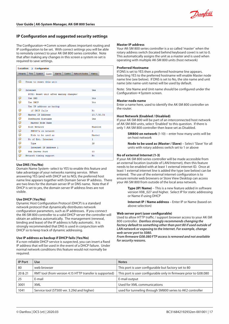
IP Configuration and suggested security settings
Use DNS (Yes/No)Domain Name System- select to YES to enable this feature and take advantage of your networks naming service. When answering YES (and with DHCP set to NO), the preferred host name line appears together with Domain Server IP address. There are two lines for the domain server IP or DNS name. Note that if DHCP is set to yes, the domain server IP address lines are not visible.
Use DHCP (Yes/No)Dynamic Host Configuration Protocol (DHCP) is a standard network protocol that dynamically distributes network configuration parameters, such as IP addresses. If you connect the AK-SM 800 controller to a valid DHCP server the controller will obtain an address automatically. The management (renewal, binding and lease) of the IP address is fully automatic. It is strongly recommended that DNS is used in conjunction with DHCP so to keep track of dynamic addressing.
Use IP address as backup if DHCP fails (Yes/No)If a non-reliable DHCP service is suspected, you can insert a fixed IP address that will be used in the event of a DHCP failure. Under normal network conditions this feature would not normally be required.
The ConfigurationComm screen allows important routing and IP configuration to be set. With correct settings you will be able to remotely connect to your AK-SM 800 series controller. Note that after making any changes in this screen a system re-set is required to save settings.
Master IP addressYour AK-SM 800 series controller is a so called ‘master’ when the rotary address switch (located behind keyboard cover) is set to 0. This automatically assigns the unit as a master and is used when operating with multiple AK-SM 800 units (host network)
Preferred HostnameIf DNS is set to YES then a preferred hostname line appears. Selecting YES to the preferred hostname will enable Master node name line (see below). If DNS is set to No, the site name and unit name (site name-unit name) will be used by default.
Note: Site Name and Unit name should be configured under the ConfigurationSystem screen.
Master node nameEnter a name here, used to identify the AK-SM 800 controller on the router.
Host Network (Enabled / Disabled)If your AK-SM 800 will be part of an interconnected host network of AK-SM 800 units, select ‘Enabled’ to this question. If there is only 1 AK-SM 800 controller then leave set as Disabled.
SM800 on network (1-10) – enter how many units will be on host network
Node to be used as (Master / Slave) – Select ‘Slave’ for all units with rotary address switch set to 1 or above
No of external Internet (1-3)If your AK-SM 800 series controller will be made accessible from an external location (outside of LAN/Internet), then this feature needs to be enabled with at least 1 external internet ID. Once at least 1 external internet line is added the type (see below) can be entered. The use of the external internet configuration is to ensure remote web browsers or Store View Desktop can access your AK-SM 800 from outside of the local area network.
Type (IP/ Name) – This is a new feature added in software version V08_027 and higher. Select IP for static addressing or Name if using DHCP
Internet IP / Name address – Enter IP or Name (based on above selection)
Web server port (user configurable)Used to allow HTTP traffic / support browser access to your AK-SM 800 controller. Danfoss strongly recommends changing the factory default to something other than port 80 if used outside of LAN network or exposing to the Internet. For example, change web server port to 5080.From firmware G08.080 FTP access is removed and not available for security reasons.

User Guide | AK-System Manager, AK-SM 800 Series
18 | BC316842192932en-001001 © Danfoss | DCS (vt) | 2020.03
FTP Server port (user configurable)The AK-SM 800 series controller uses ‘Active’ FTP. Used to transfer database and EDF files. Danfoss strongly recommends changing the factory default to something other than port 21
FTP Data port (user configurable)The port used to support file transfer
Network timing support (NTP)Use this function (if supported by your network) to sync the AK-SM 800 real time clock over the network, known as NTP. Requires NTP sever address and Time Zone offset to be programed.
Note: Time Zone offset can be configured under the ConfigurationTime screen
General IT security / Recommendations
The AK-SM 800 series device is an embedded controller designed to be installed behind an appropriate router and firewall. The AK-SM 800 itself does not offer routing or firewall options, additional security steps must be taken to secure appropriate levels of security dependent on the application needs.
Danfoss recommends changing the default user name and password, used to log into the AK-SM 800 series controller.
Danfoss recommends changing the default web server port if used outside of secure LAN network.
Ensure the AK-SM 800 is behind a well configured firewall(i.e. port forwarding rules, FTP access (FTP is disabled from firmware version G08.080.054), HTTP access). A well configured router/firewall will help in;
Firewall between our controllers and the Internet
The ability to designate the ports/protocols allowed to our controllers
The ability to limit and monitor in-store IP connections to our controllers.
The AK-SM 800 controller supports auto negotiated 10/100 Ethernet speeds.
The AK-SM 800 controller supports auto negotiated full / half duplex Ethernet communications.
From firmware G08.080 FTP access is removed and not available for security reasons.

User Guide | AK-System Manager, AK-SM 800 Series
© Danfoss | DCS (vt) | 2020.03 BC316842192932en-001001 | 19
General navigation, operation and use (via web)Once your AK-SM has been configured, general navigation and daily use is done via the Dashboard screen. The Dashboard screen acts as the central system home page, where further system details can be reached. The Dashboard and subsequent device screens have been developed to provide an easy to use navigation environment for the user, where typical status and setting can be found.
Connecting to your AK-SMUsing a standard web browser or your StoreView Desktop application, enter your AK-SM IP address
The factory default User name & password:User Name: SupervisorPassword: 12345
To guarantee the best experience when connecting to your AK-SM, ensure you PC has the latest version of Adobe® Flash®
Dashboard viewOnce the correct user name and password has been entered the Dashboard screen will load. The Dashboard screen will only reflect what your application configuration has been set to. For example, if your application does not have any HVAC configured the Dashboard will not show the HVAC panel. Dashboard panels are automatically generated depending on the configuration, no user action is required to build the panels.
Once the correct user name and password has been entered the Dashboard screen will load. The Dashboard screen will only reflect what your application configuration has been set to. For example, if your application does not have any HVAC configured the Dashboard will not show the HVAC panel. Dashboard panels are automatically generated depending on the configuration, no user action is required to build the panels.
Upon the Dashboard loading, if any active alarms are present the built in alarm buzzer can be heard. To silence the alarm press the silence button. This does not acknowledge or clear any alarms.
Active alarm panel
Expand panel buttonData poll refresh info Refrigeration panel HVAC panel data communication status
Lighting panel Misc panel Energy panel
PreferencesRefrigeration ReportDownload ReportHistory Log CollectionAlarm Log CollectionLog Off
Use the simulator tool to simulate configured Misc
points (only available through RMT off line tool)
Global alarms (all connected
AK-SM units)
Device detail screen Info screen (software version, etc)
Central AK-SM configuration screens
Dashboard screen System View screen Schedule screen History (logs)
Chapter 3: Navigation and use
User Guide | AK-System Manager, AK-SM 800 Series
20 | BC316842192932en-001001 © Danfoss | DCS (vt) | 2020.03
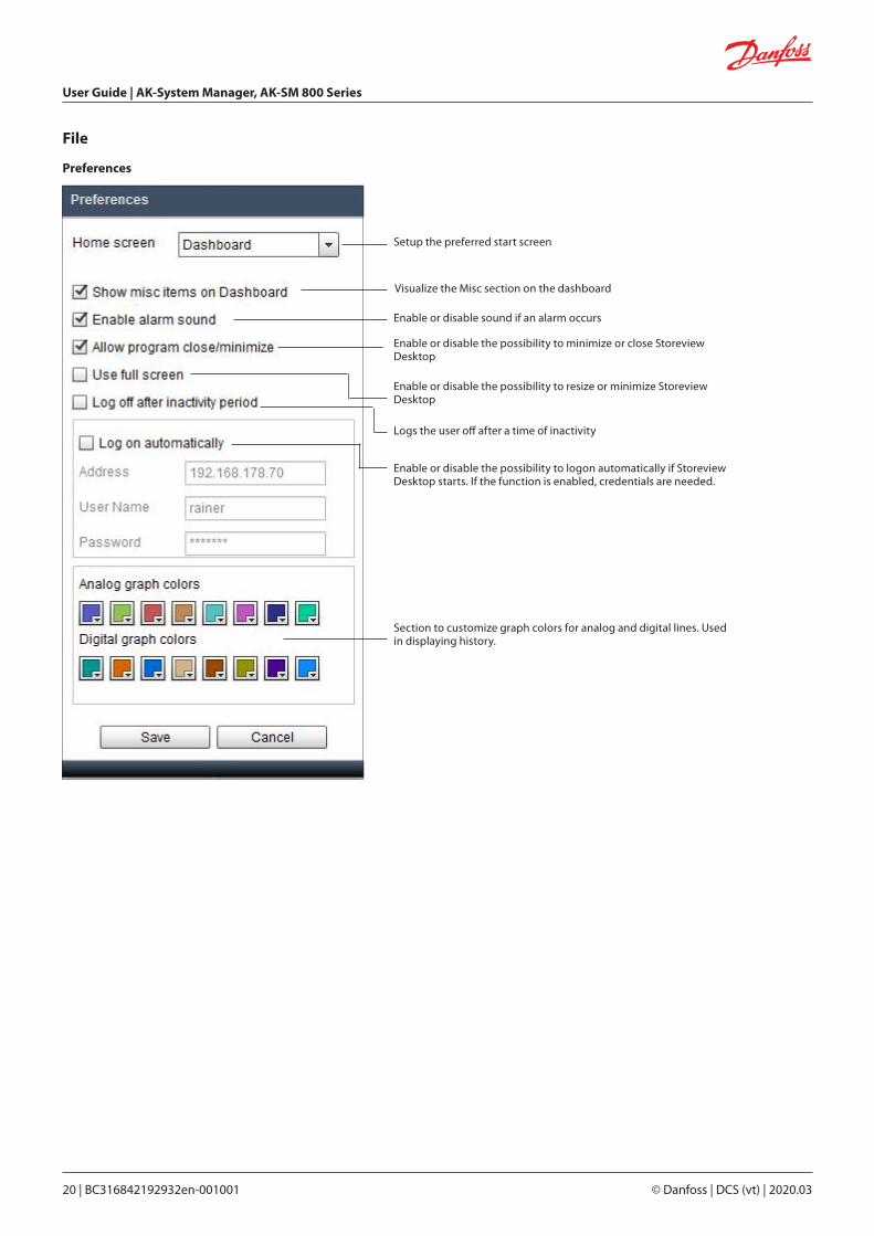
File
Preferences
Setup the preferred start screen
Visualize the Misc section on the dashboard
Enable or disable sound if an alarm occurs
Enable or disable the possibility to minimize or close Storeview Desktop
Enable or disable the possibility to resize or minimize Storeview Desktop
Logs the user off after a time of inactivity
Enable or disable the possibility to logon automatically if Storeview Desktop starts. If the function is enabled, credentials are needed.
Section to customize graph colors for analog and digital lines. Used in displaying history.
User Guide | AK-System Manager, AK-SM 800 Series
© Danfoss | DCS (vt) | 2020.03 BC316842192932en-001001 | 21
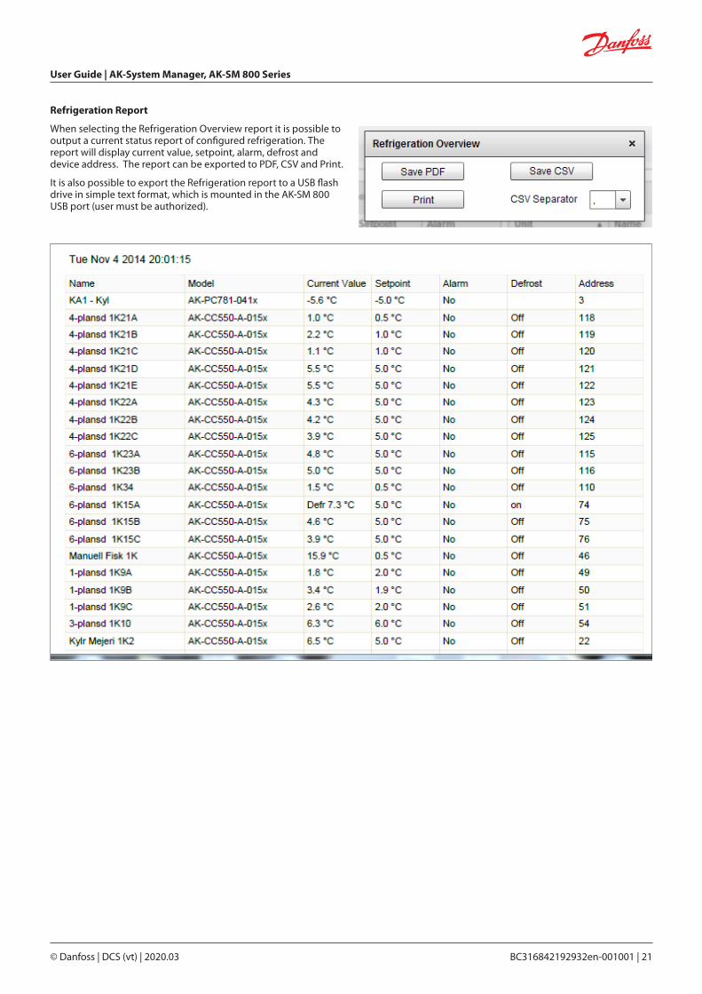
Refrigeration Report
When selecting the Refrigeration Overview report it is possible to output a current status report of configured refrigeration. The report will display current value, setpoint, alarm, defrost and device address. The report can be exported to PDF, CSV and Print.
It is also possible to export the Refrigeration report to a USB flash drive in simple text format, which is mounted in the AK-SM 800 USB port (user must be authorized).
User Guide | AK-System Manager, AK-SM 800 Series
22 | BC316842192932en-001001 © Danfoss | DCS (vt) | 2020.03
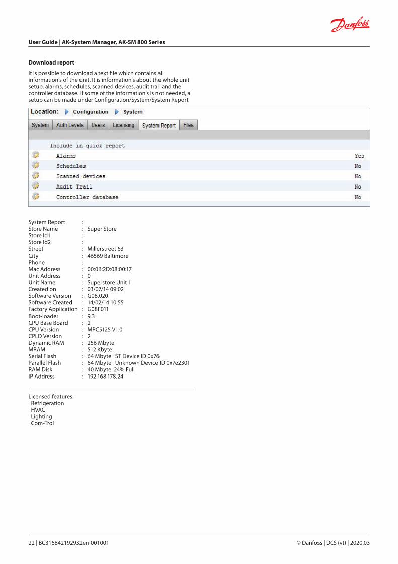
Download report
It is possible to download a text file which contains all information’s of the unit. It is information’s about the whole unit setup, alarms, schedules, scanned devices, audit trail and the controller database. If some of the information’s is not needed, a setup can be made under Configuration/System/System Report
System Report : Store Name : Super StoreStore Id1 : Store Id2 : Street : Millerstreet 63City : 46569 BaltimorePhone : Mac Address : 00:0B:2D:08:00:17Unit Address : 0Unit Name : Superstore Unit 1Created on : 03/07/14 09:02Software Version : G08.020 Software Created : 14/02/14 10:55Factory Application : G08F011Boot-loader : 9.3CPU Base Board : 2CPU Version : MPC5125 V1.0CPLD Version : 2Dynamic RAM : 256 MbyteMRAM : 512 KbyteSerial Flash : 64 Mbyte ST Device ID 0x76Parallel Flash : 64 Mbyte Unknown Device ID 0x7e2301RAM Disk : 40 Mbyte 24% FullIP Address : 192.168.178.24
Licensed features: Refrigeration HVAC Lighting Com-Trol

User Guide | AK-System Manager, AK-SM 800 Series
© Danfoss | DCS (vt) | 2020.03 BC316842192932en-001001 | 23
Auto History Log CollectionThe user can create with Store view Desktop a daily or weekly export of Log data. The computer running Store View must be permanently connected to the AK-SM 800 network and remain running in order to auto collect log data.
The file format can be CSV for further use in Excel or other tools or HST to reread the data with Store view Desktop. To export Store view Desktop must be connected to the AK-SM 800.
Conditions, if the frequently export is always used:1. Add Store view Desktop to the PC auto start section2. Disable in “Preferences” the log off after inactivity period3. Enable the auto logon feature and set the credentials
Select the sample rate for the exported file
Enable/Disable the auto collection
Selection of the file format
Separator for CSV (, or ;)
Collection rate daily or weekly
Select the destination folder for theexported files
Selection of data points

User Guide | AK-System Manager, AK-SM 800 Series
24 | BC316842192932en-001001 © Danfoss | DCS (vt) | 2020.03
The user can create with Store view Desktop a daily or weekly export of alarms.
The computer running Store View must be permanently connected to the AK-SM 800 network and remain running in order to auto collect alarm data.
Auto Alarm Log Collection
Collection rates:Hourly – no additional setup is neededDaily – Time stamp is neededWeekly – Time stamp and day of the week is neededMonthly – Time stamp and day of the month is needed
Conditions, if the frequently export is used:1. Add Store view Desktop to the PC auto start section2. Disable in “Preferences” the log off after inactivity period3. Enable the auto logon feature and set the credentials
Enable/Disable the auto collection
Export of all alarms or only active, acknowledged or cleared alarms
Separator for CSV (, or ;)
Select the destination folder for theexported files
Collection rate hourly,daily, weekly, monthly
User Guide | AK-System Manager, AK-SM 800 Series
© Danfoss | DCS (vt) | 2020.03 BC316842192932en-001001 | 25
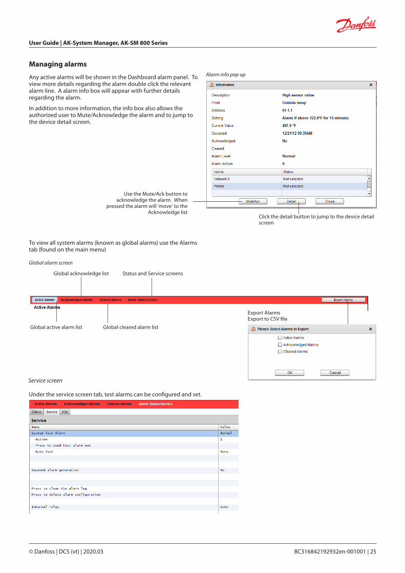
Managing alarms
Any active alarms will be shown in the Dashboard alarm panel. To view more details regarding the alarm double click the relevant alarm line. A alarm info box will appear with further details regarding the alarm.
In addition to more information, the info box also allows the authorized user to Mute/Acknowledge the alarm and to jump to the device detail screen.
Click the detail button to jump to the device detail screen
Use the Mute/Ack button to acknowledge the alarm. When
pressed the alarm will ‘move’ to the Acknowledge list
Global active alarm list
Global acknowledge list
Global cleared alarm list
Status and Service screens
Export Alarms Export to CSV file
Global alarm screen
Service screen
Alarm info pop up
Under the service screen tab, test alarms can be configured and set.
To view all system alarms (known as global alarms) use the Alarms tab (found on the main menu)

User Guide | AK-System Manager, AK-SM 800 Series
26 | BC316842192932en-001001 © Danfoss | DCS (vt) | 2020.03
Device detail
Whilst the Dashboard screen will show basic asset information (AK-SM unit address, Asset Name, Value, Status and alarm), more detailed information can be found by double clicking an asset line in the Dashboard. The resulting device detail screen will reflect more details and settings. The device detail screen is designed to provide key status and operational settings for the selected device. Easy navigation to other assets is done via the navigation tree. The screen image below highlights some of the main areas of the device detail screen.
Advanced screen
Use the ‘Advanced view’ screen to access Measurements and Settings side by side. This screen is useful to access all read/write parameters for the particular controller
Navigation TreeDevice alarms/History/Schedules and Advanced View
‘Snap shot’ history
Full screen buttonController group menu (based on the controller type)
Status | Settings | Manual Operation tabs
StatusUnder the status tab, common read only datapoints are shownSettingsUnder the settings tab, read and write values can be shown. Double click a line to make changes (if authorized)Manual OperationUnder the Manual Operation tab, key user override functions are available

User Guide | AK-System Manager, AK-SM 800 Series
© Danfoss | DCS (vt) | 2020.03 BC316842192932en-001001 | 27
System view
The system view provides a generic yet graphical view of your configured controls.
The same principle of the navigation tree can be seen in the left side of the screen. The system view screen shows any configured Rack or Pack, with associated evaporator circuits. To see additional information, hover your mouse pointer over an icon, a pop up box will appear showing additional information. To view additional information and gain access to settings click the ‘show Detail’ button. A dashboard will slide across, where a Status, Settings and Manual operation can be seen. Simply click an asset to highlight and the detail table will update with reference to this selected device. Once complete with the device settings, close the dashboard by clicking the ‘Hide Detail’ button.
Gain access to more details via the ‘Show Details’ button
System View (Refrigeration)
User Guide | AK-System Manager, AK-SM 800 Series
28 | BC316842192932en-001001 © Danfoss | DCS (vt) | 2020.03
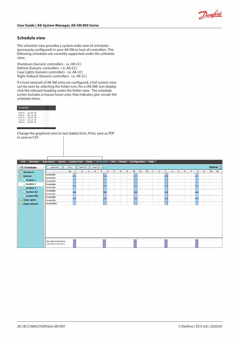
Schedule view
The schedule view provides a system wide view of schedules (previously configured) in your AK-SM or host of controllers. The following schedules are currently supported under the schedule view;
Shutdown (Generic controllers - i.e. AK-CC)Defrost (Generic controllers - i.e. AK-CC)Case Lights (Generic controllers - i.e. AK-CC)Night Setback (Generic controllers - i.e. AK-CC)
If a host network of AK-SM units are configured, a full system view can be seen by selecting the folder icon, for a (AK-SM) unit display click the relevant heading under the folder view. The schedule screen includes a mouse hover over, that indicates (per circuit) the schedule times.
Change the graphical view to text (table) form, Print, save as PDF or save as CSV

User Guide | AK-System Manager, AK-SM 800 Series
© Danfoss | DCS (vt) | 2020.03 BC316842192932en-001001 | 29
History (Logs)
History Tool barWhen viewing data in the history view the tool bar has a set of functions to enable various actions to be performed.
To access your AK-SM history, select the history tab. Upto 8 datapoints can be viewed at any given time on the history screen.
Page controlPreferences
Zoom
Save history group to file
(Creates a file that contains defined parameters. This saves time locating the parameters when loading a graph)
Load history group from file
Convert history file to .CSV
Export history functionExport to .hst or csv file format. Saving the collected history points (as .hst) will allow the user to re-load these at a later date (via the ‘load history from file’ button
Load history from file
Load a saved .hst file to view
User Guide | AK-System Manager, AK-SM 800 Series
30 | BC316842192932en-001001 © Danfoss | DCS (vt) | 2020.03
Save History Group to file (saving time for frequent datapoint selections)This feature allows the user to save a set of history datapoints. Typically this feature would be used when a set of datapoints is frequently needed to be loaded and viewed. Once the datapoints are saved, this history group can then be easily loaded - thus saving time in selecting datapoints.
Load History Group from fileUse this feature to load any previously save datapoint groups. When opening the history group file the system will prompt for the file location. Once loaded a ‘select datapoint’ box will appear with the datapoints already pre-selection
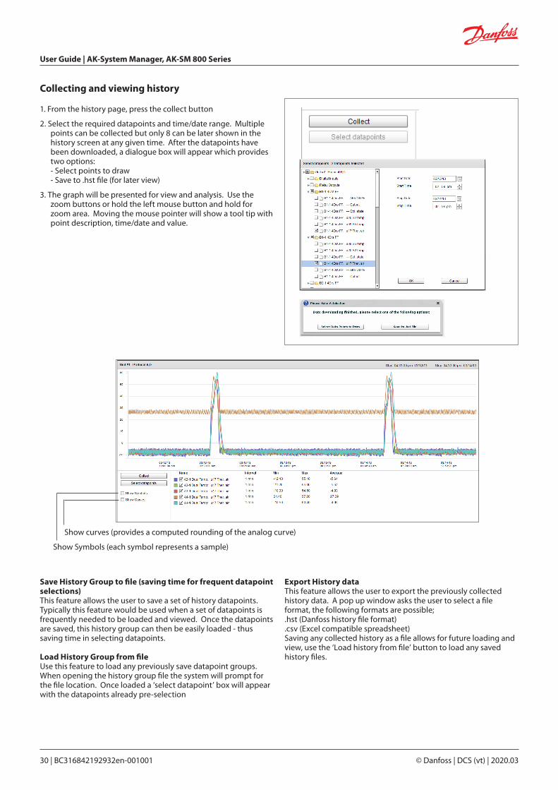
Collecting and viewing history
1. From the history page, press the collect button
2. Select the required datapoints and time/date range. Multiple points can be collected but only 8 can be later shown in the history screen at any given time. After the datapoints have been downloaded, a dialogue box will appear which provides two options:
- Select points to draw - Save to .hst file (for later view)
3. The graph will be presented for view and analysis. Use the zoom buttons or hold the left mouse button and hold for zoom area. Moving the mouse pointer will show a tool tip with point description, time/date and value.
Show curves (provides a computed rounding of the analog curve)
Show Symbols (each symbol represents a sample)
Export History dataThis feature allows the user to export the previously collected history data. A pop up window asks the user to select a file format, the following formats are possible;.hst (Danfoss history file format).csv (Excel compatible spreadsheet)Saving any collected history as a file allows for future loading and view, use the ‘Load history from file’ button to load any saved history files.

User Guide | AK-System Manager, AK-SM 800 Series
© Danfoss | DCS (vt) | 2020.03 BC316842192932en-001001 | 31
The following section describes the typical steps required for commissioning and configuration of your AK-SM. Although site applications can differ from one site to another, many setup procedures are common. This setup section assumes the AK-SM is mounted and all necessary power, network cabling and controllers are in place. The described work flow is based around the AK-SM web browser interface, but would equally apply if being done via the local screen. Further detailed commissioning instructions are found throughout this user guide.
The AK-SM offers unique control flexibility in that both centralized and de-centralized control methods are supported. The term ‘centralized’ is used to describe the control of refrigeration Racks via I/O (Danfoss Input / Output modules). Under this method of control the refrigeration control is managed directly from the front end (AK-SM), with field bus I/O. De-centralized control is the term used to describe the full support of Danfoss Pack and Case controllers. Under this method, each Pack or Case controller on the network can be seen as self contained, with control logic built in. The front end (AK-SM) under this type of application is more of a network manager, providing full read / write access and energy saving functions.
When starting your system configuration you will have the opportunity to select either Centralized or De-centralized (or a mix of both) control methods.
Chapter 4: Configuration
CentralizedDe-Centralized
Pack & Case Rack I/O
When configuring your application, have in mind which control strategy you wish to utilise.
The following areas of system configuration will be covered in this section:
1. Initial configuration - web wizard and copy wizard
2. Network Nodes (Network scan/ Node overview, Points, scan /config status, duplicates, upload/download)
3. Time (Set time/date, time zone, operating Hours, Daylight savings, Holidays)
4. System (Store / Region Names, Units preferences, Authorization levels and users)
5. Communication (DNS, DHCP, IP Ports)
6. Alarms (XML, e-mail, Routing)
7. Control (Configure Refrigeration, Lighting, Miscellaneous, Energy meters and Gas detection)
Once successfully logged into the AK-SM (web) and assuming you have the required authorization, system configuration is done via the central ‘Configuration tab’. Clicking this tab reveals the configuration ‘sub tabs’. Depending on your selection, these sub tabs will change dependent on content.
Using the menu structure seen in the ‘Configuration’ page, a step by step process can be applied when setting up your AK-SM.
Navigation ‘bread-crumb’ Central configuration menu
User Guide | AK-System Manager, AK-SM 800 Series
32 | BC316842192932en-001001 © Danfoss | DCS (vt) | 2020.03
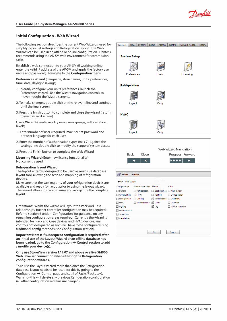
The following section describes the current Web Wizards, used for simplifying initial settings and Refrigeration layout. The Web Wizards can be used in an offline or online configuration. Danfoss recommends using the AK-SM web environment for commission tasks.
Establish a web connection to your AK-SM (if working online, enter the valid IP address of the AK-SM and apply the factory user name and password). Navigate to the Configuration menu
Preferences Wizard (Language, store names, units, preferences, time, date, daylight savings)
1. To easily configure your units preferences, launch the Preferences wizard. Use the Wizard navigation controls to move thought the Wizard screens.
2. To make changes, double click on the relevant line and continue until the final screen.
3. Press the finish button to complete and close the wizard (return to main wizard screen)
Users Wizard (Create, modify users, user groups, authorization levels)
1. Enter number of users required (max 22), set password and browser language for each user
2. Enter the number of authorization types (max 7), against the settings line double click to modify the scope of system access
3. Press the Finish button to complete the Web Wizard
Licensing Wizard (Enter new license functionality)Not currently used
Refrigeration layout WizardThe layout wizard is designed to be used as multi use database layout tool, allowing the scan and mapping of refrigeration devices. Make sure that the vast majority of your refrigeration devices are available and ready for layout prior to using the layout wizard.The wizard allows to scan organize and reorganize the complete layout.
Limitations: Whilst the wizard will layout the Pack and Case relationships, further controller configuration may be required. Refer to section 6 under ‘ Configuration’ for guidance on any remaining configuration areas required. Currently the wizard is intended for Pack and Case devices and HVAC devices, any controls not designated as such will have to be configured using traditional config methods (see Configuration section).
Important Notes: If subsequent configuration is required after an initial use of the Layout Wizard or an offline database has been loaded, go to the Configuration Control section to add / modify your device(s).
Only use StoreView version 1.19.07 and above or a live SM800 Web Browser connection when utilizing the Refrigeration configuration wizards.
To re-use the Layout wizard more than once the Refrigeration database layout needs to be reset- do this by going to the Configuration Control page and set # of Racks/Packs to 0. Warning- this will delete any previous Refrigeration configuration (all other configuration remains unchanged)
Initial Configuration - Web Wizard
Web Wizard Navigation
Back Close Progress Forward
User Guide | AK-System Manager, AK-SM 800 Series
© Danfoss | DCS (vt) | 2020.03 BC316842192932en-001001 | 33
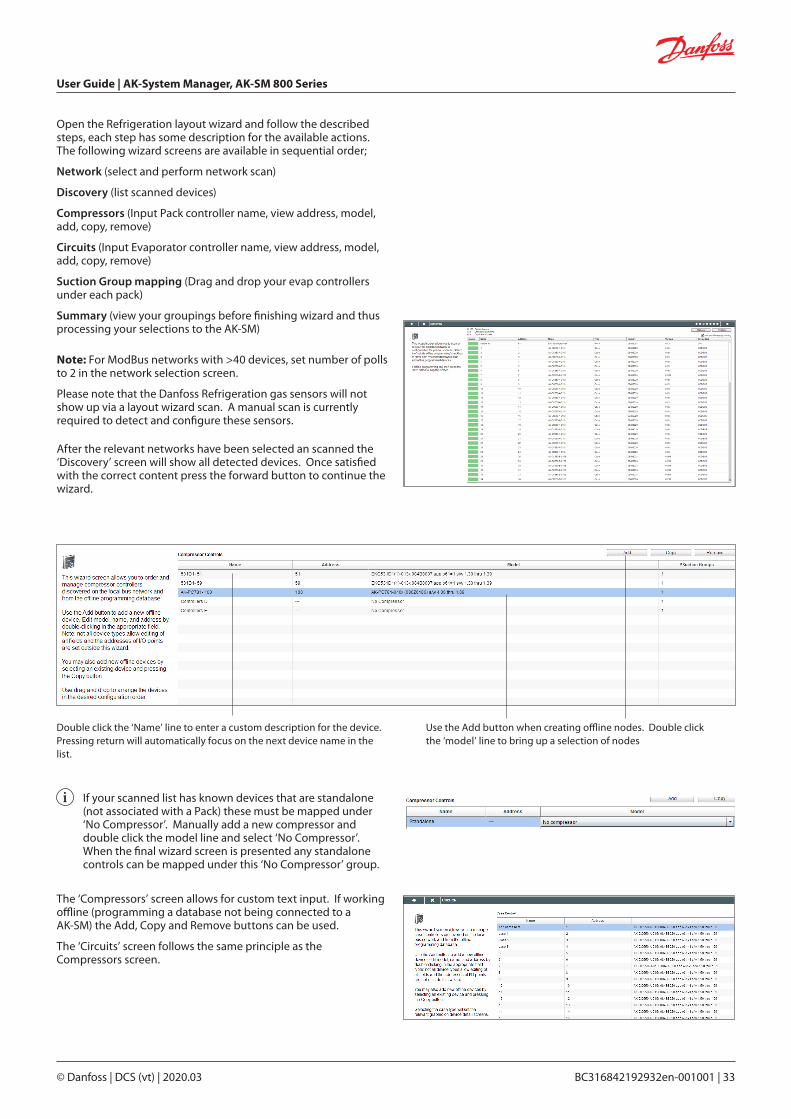
Open the Refrigeration layout wizard and follow the described steps, each step has some description for the available actions. The following wizard screens are available in sequential order;
Network (select and perform network scan)
Discovery (list scanned devices)
Compressors (Input Pack controller name, view address, model, add, copy, remove)
Circuits (Input Evaporator controller name, view address, model, add, copy, remove)
Suction Group mapping (Drag and drop your evap controllers under each pack)
Summary (view your groupings before finishing wizard and thus processing your selections to the AK-SM)
Use the Add button when creating offline nodes. Double click the ‘model’ line to bring up a selection of nodes
Double click the ‘Name’ line to enter a custom description for the device. Pressing return will automatically focus on the next device name in the list.
If your scanned list has known devices that are standalone (not associated with a Pack) these must be mapped under ‘No Compressor’. Manually add a new compressor and double click the model line and select ‘No Compressor’. When the final wizard screen is presented any standalone controls can be mapped under this ‘No Compressor’ group.
After the relevant networks have been selected an scanned the ‘Discovery’ screen will show all detected devices. Once satisfied with the correct content press the forward button to continue the wizard.
The ‘Compressors’ screen allows for custom text input. If working offline (programming a database not being connected to a AK-SM) the Add, Copy and Remove buttons can be used.
The ‘Circuits’ screen follows the same principle as the Compressors screen.
Note: For ModBus networks with >40 devices, set number of polls to 2 in the network selection screen.
Please note that the Danfoss Refrigeration gas sensors will not show up via a layout wizard scan. A manual scan is currently required to detect and configure these sensors.

User Guide | AK-System Manager, AK-SM 800 Series
34 | BC316842192932en-001001 © Danfoss | DCS (vt) | 2020.03
The ‘Suction group mapping’ screen allows for the defined evaporator devices to be ‘mapped’ under the required Pack controller. This mapping forms a relationship or grouping between the pack and the evaporator devices. This grouping association will then be seen in the AK-SM configuration and dashboard screens (and can be used to easily set up master control functions like Suction optimization).
As the user description indicates, use a drag and drop action to group your controls. Use the CTRL key and multi-select cases to save time when making bulk actions. You can remove any case devices by simply dragging back to the available case list.
The check box labelled ‘Allow multi-case circuit creation’ is to support Centralized refrigeration control configuration, where multiple case circuits are available’. Leave this check box empty if you are using a de-centralized control strategy (i.e. Case and pack controllers).
Once satisfied with the mapping, press the forward button and the summary screen will be shown. Pressing the finish button will then send your configuration layout to the AK-SM. During this time a progress bar will be shown and finally a status dialogue box.
This completed wizard process will layout your refrigeration application. Typically some additional configuration tasks will then need to be completed (i.e. define alarms, setpoint changes, configure history), please refer to the following section for further details on detailed configuration.

User Guide | AK-System Manager, AK-SM 800 Series
© Danfoss | DCS (vt) | 2020.03 BC316842192932en-001001 | 35
Before performing the copy function ensure your SM 800 database is in sync with any control devices on line – refer to previous section ‘System Upload / Download’ before starting copy wizard’
The copy wizard is designed to speed up the commissioning workflow by providing the ability to define a ‘source’ device and then copy the settings to like type devices. In addition to controller settings, the copy wizard also provides the ability to define and copy alarm controller configuration and history point configuration. A new feature added under the copy wizard for version G08_031 is the ability to save / load controller settings to and from a file.
During normal operations, your AK-SM 800 auto polls certain online controller parameters to sustain communications and to refresh key parameters at regular intervals. Please note that during the copy wizard process auto polling is temporarily suspended. Polling is stopped when you reach the parameter configuration screen. Auto polling will resume after a max 2Hr timeout or completion of wizard task or if wizard is cancelled, whichever is first. To cancel the wizard at any time only use the top left close ‘X’ button.
Some Danfoss controllers require that the ‘Main switch’ is OFF before allowing any parameter changes. To accommodate this fact, the copy wizard will automatically turn off the main switch for the source and destination controller(s). The main switch will be reverted to original position after the copy or copy/download is completed. Since the copy wizard changes the state of the device main switch, please pay special attention to operational conditions (i.e. food temperature) during this operation and validate all devices are correctly running after copy completion or cancellation of copy wizard. Failure to review device status may result in devices being left with main switch off (i.e. no refrigeration).
Important limitationsThe copy wizard is currently not designed to fully support the Danfoss AK2 platform of devices (i.e. AK-PC 781, AK-CC 750..) since these devices have a different framework than other Danfoss controllers. When using the copy wizard in an on-line environment (connect to active controller network) the copy wizard will only allow ‘Alarms and History’ points to be set and copied. For full configuration of AK2 device parameters Danfoss recommends using the available Service Tool to facilitate commissioning on these device types.
Copy Wizard
Before using the copy wizard make sure the source device is fully configured (settings, history, alarms). Whilst it is possible to use the copy wizard to set up the source device, it is not recommended and has been seen that potential errors can occur with this workflow – please configure the source device first (outside of the copy wizard). Once source device is configured the copy wizard can be used, do not make any changes (settings, alarms, history) to the source device whilst in the copy wizard.
When copying history. Be aware, that the copy process always keeps existing logs in the destination and new logs will be added.
BE SURE TO VALIDATE MAIN SWITCH STATUS AFTER COPY WIZARD
Note: When assigning history points to a controller device a recommended max of 100 points per device is allowed. Assigning more than 100 points per device will cause points not to record log history.
Please note that the copy function will only work against same device, application/code type and is not designed to fully support Danfoss AK2 style controllers.
Preparation
Online ConfigurationFor onsite (online) commissioning, the copy wizard assumes all relevant controller devices are installed on the network, have correct addressing, and if relevant application type set. Naming of the asset will also help in the copy wizard due to easy recognition of your devices. The ‘Layout wizard’ can assist in this preliminary task.
During the final copy/download phase, the main switch of the target device(s) will be switched off then on after the copy/download is complete.
Offline Configuration
The copy wizard can be used in an online or offline (via RMT simulator) environment.
User Guide | AK-System Manager, AK-SM 800 Series
36 | BC316842192932en-001001 © Danfoss | DCS (vt) | 2020.03
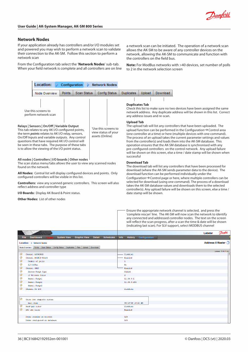
Network NodesIf your application already has controllers and/or I/O modules set and powered you may wish to perform a network scan to validate their connection to the AK-SM. Follow this section to perform a network scan
From the Configuration tab select the ‘Network Nodes’ sub-tab. When your field network is complete and all controllers are on line
Ensure the appropriate network channel is selected, and press the ‘complete rescan’ line. The AK-SM will now scan the network to identify any connected and addressed controller nodes. The text on the screen will reflect the scan progress, after a scan the time & date will be shown (indicating last scan). For SLV support, select MODBUS channel
All nodes | Controllers | I/O boards | Other nodesThe scan status menu/tabs allows the user to view any scanned nodes found on the network.
All Nodes: Central list will display configured devices and points. Only configured controllers will be visible in this list.
Controllers: view any scanned generic controllers. This screen will also reflect address and controller type
I/O Boards: Display AK Board & Point status.
Other Nodes: List of other nodes
Relays | Sensors | On/Off | Variable OutputThis tab relates to any AK I/O configured points, the term points relates to AK I/O relay, sensors, On/Off Inputs and variable outputs. Any control questions that have required AK I/O control will be seen in these tabs. The purpose of these tabs is to allow the viewing of the I/O point status.
‘Use this screens to view status of your assets (Online)
Use this screens to perform network scan
Duplicates TabCheck this list to make sure no two devices have been assigned the same network address. Any duplicate address will be shown in this list. Correct any address issues and re-scan.
Upload TabThe upload tab will list any controllers that have been uploaded. The upload function can be performed in the ConfigurationControl area (one controller at a time) or here (multiple devices with one command). The process of an upload takes the current parameter settings and values from the controller(s) and loads them into the AK-SM database. This operation ensures that the AK-SM database is synchronised with any pre-configured controllers on the control network. Any upload failure will be shown on this screen, else a time / date stamp will be shown when successful
Download TabThe download tab will list any controllers that have been processed for download (where the AK-SM sends parameter data to the device). The download function can be performed individually under the ConfigurationControl page or here, where multiple controllers can be selected for download (using one command). The process of a download takes the AK-SM database values and downloads them to the selected controller(s). Any upload failure will be shown on this screen, else a time / date stamp will be shown.
a network scan can be initiated. The operation of a network scan allows the AK-SM to be aware of any controller devices on the network, allowing the AK-SM to communicate and function with the controllers on the field bus.
Note: For ModBus networks with >40 devices, set number of polls to 2 in the network selection screen
User Guide | AK-System Manager, AK-SM 800 Series
© Danfoss | DCS (vt) | 2020.03 BC316842192932en-001001 | 37
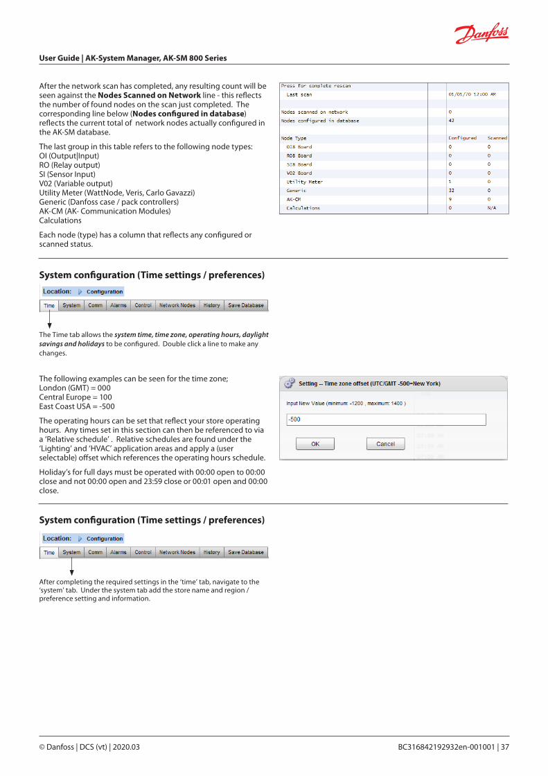
The Time tab allows the system time, time zone, operating hours, daylight savings and holidays to be configured. Double click a line to make any changes.
After the network scan has completed, any resulting count will be seen against the Nodes Scanned on Network line - this reflects the number of found nodes on the scan just completed. The corresponding line below (Nodes configured in database) reflects the current total of network nodes actually configured in the AK-SM database.
The last group in this table refers to the following node types:OI (Output|Input)RO (Relay output)SI (Sensor Input)V02 (Variable output)Utility Meter (WattNode, Veris, Carlo Gavazzi)Generic (Danfoss case / pack controllers)AK-CM (AK- Communication Modules)Calculations
Each node (type) has a column that reflects any configured or scanned status.
The following examples can be seen for the time zone;London (GMT) = 000Central Europe = 100East Coast USA = -500
The operating hours can be set that reflect your store operating hours. Any times set in this section can then be referenced to via a ‘Relative schedule’ . Relative schedules are found under the ‘Lighting’ and ‘HVAC’ application areas and apply a (user selectable) offset which references the operating hours schedule.
Holiday’s for full days must be operated with 00:00 open to 00:00 close and not 00:00 open and 23:59 close or 00:01 open and 00:00 close.
System configuration (Time settings / preferences)
System configuration (Time settings / preferences)
After completing the required settings in the ‘time’ tab, navigate to the ‘system’ tab. Under the system tab add the store name and region / preference setting and information.
User Guide | AK-System Manager, AK-SM 800 Series
38 | BC316842192932en-001001 © Danfoss | DCS (vt) | 2020.03
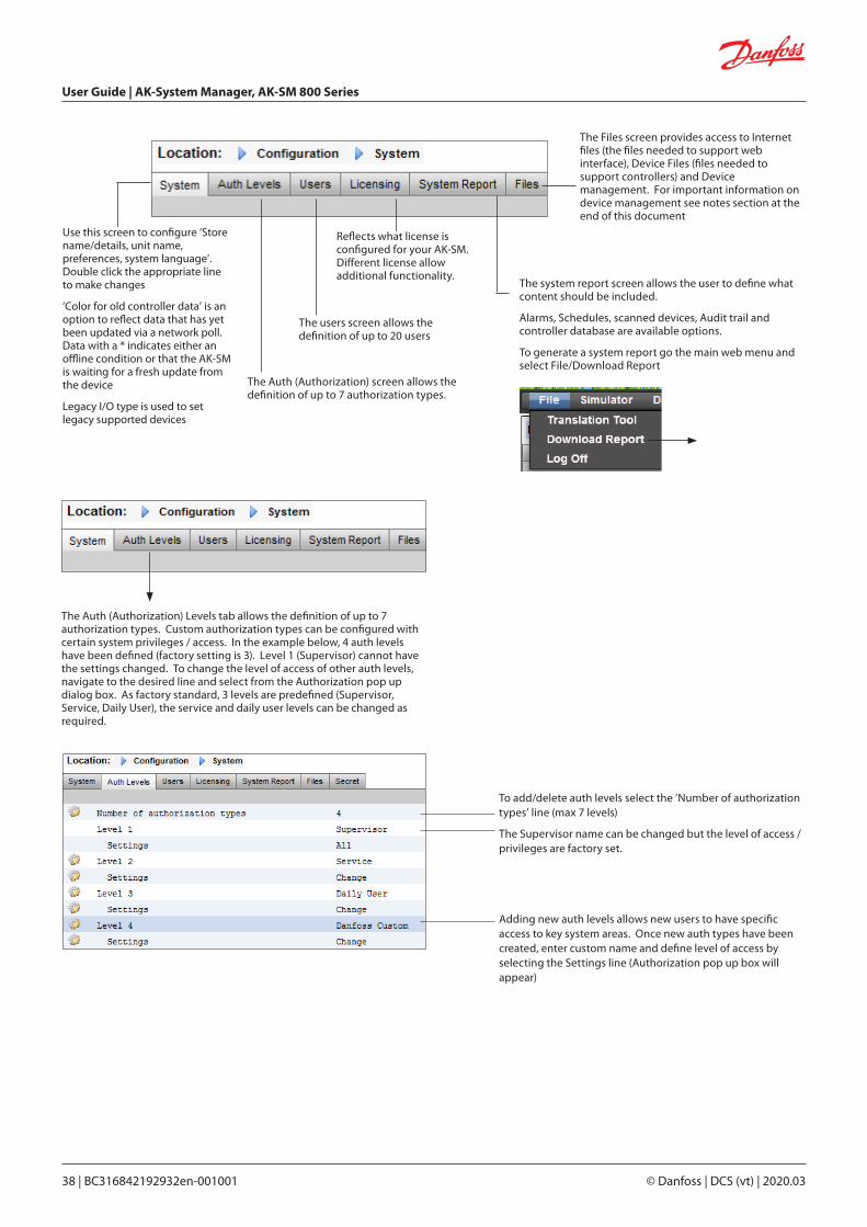
The Auth (Authorization) Levels tab allows the definition of up to 7 authorization types. Custom authorization types can be configured with certain system privileges / access. In the example below, 4 auth levels have been defined (factory setting is 3). Level 1 (Supervisor) cannot have the settings changed. To change the level of access of other auth levels, navigate to the desired line and select from the Authorization pop up dialog box. As factory standard, 3 levels are predefined (Supervisor, Service, Daily User), the service and daily user levels can be changed as required.
To add/delete auth levels select the ‘Number of authorization types’ line (max 7 levels)
The Supervisor name can be changed but the level of access / privileges are factory set.
Adding new auth levels allows new users to have specific access to key system areas. Once new auth types have been created, enter custom name and define level of access by selecting the Settings line (Authorization pop up box will appear)
Use this screen to configure ‘Store name/details, unit name, preferences, system language’. Double click the appropriate line to make changes
‘Color for old controller data’ is an option to reflect data that has yet been updated via a network poll. Data with a * indicates either an offline condition or that the AK-SM is waiting for a fresh update from the device
Legacy I/O type is used to set legacy supported devices
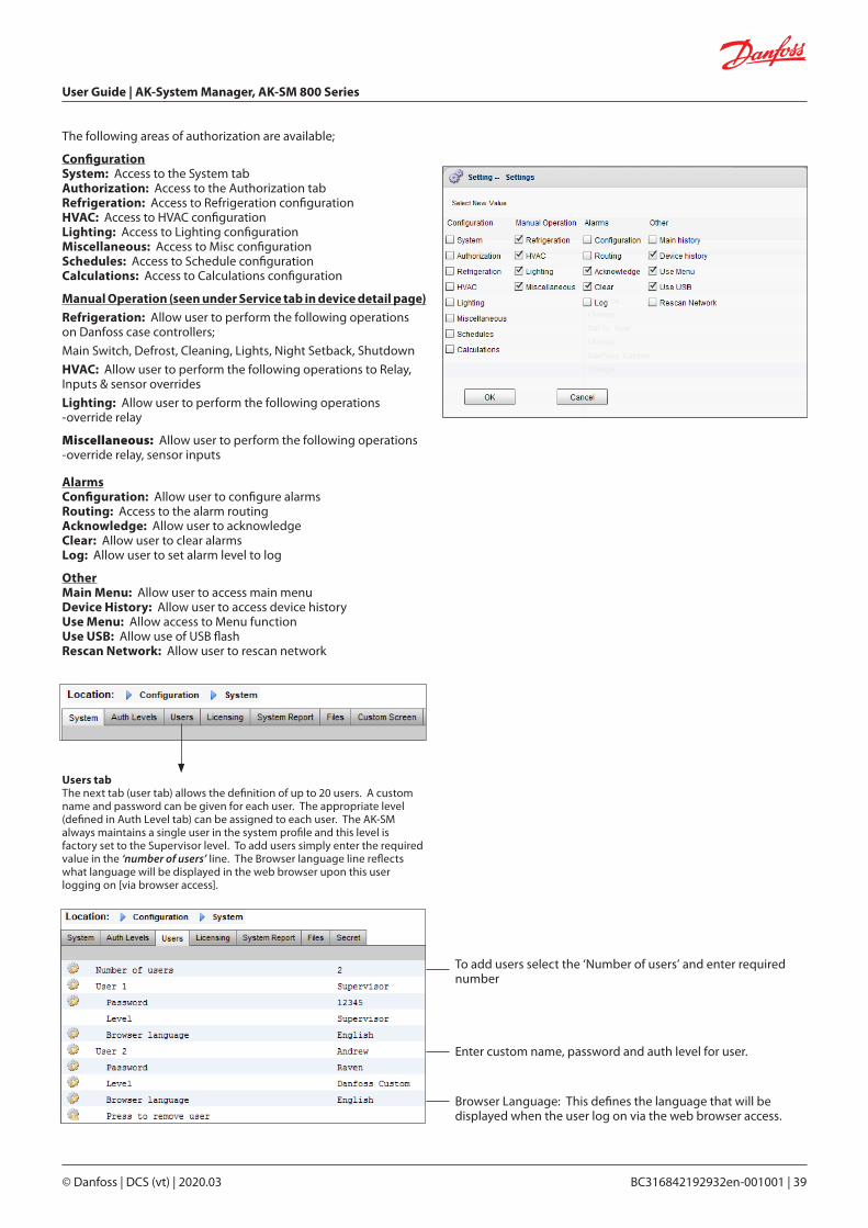
The users screen allows the definition of up to 20 users
The Auth (Authorization) screen allows the definition of up to 7 authorization types.
Reflects what license is configured for your AK-SM. Different license allow additional functionality.
The system report screen allows the user to define what content should be included.
Alarms, Schedules, scanned devices, Audit trail and controller database are available options.
To generate a system report go the main web menu and select File/Download Report
The Files screen provides access to Internet files (the files needed to support web interface), Device Files (files needed to support controllers) and Device management. For important information on device management see notes section at the end of this document
User Guide | AK-System Manager, AK-SM 800 Series
© Danfoss | DCS (vt) | 2020.03 BC316842192932en-001001 | 39
The following areas of authorization are available;
ConfigurationSystem: Access to the System tabAuthorization: Access to the Authorization tabRefrigeration: Access to Refrigeration configurationHVAC: Access to HVAC configurationLighting: Access to Lighting configurationMiscellaneous: Access to Misc configurationSchedules: Access to Schedule configurationCalculations: Access to Calculations configuration
Manual Operation (seen under Service tab in device detail page)Refrigeration: Allow user to perform the following operations on Danfoss case controllers;
Main Switch, Defrost, Cleaning, Lights, Night Setback, Shutdown
HVAC: Allow user to perform the following operations to Relay, Inputs & sensor overrides
Lighting: Allow user to perform the following operations -override relay
Miscellaneous: Allow user to perform the following operations -override relay, sensor inputs
AlarmsConfiguration: Allow user to configure alarmsRouting: Access to the alarm routingAcknowledge: Allow user to acknowledgeClear: Allow user to clear alarmsLog: Allow user to set alarm level to log
OtherMain Menu: Allow user to access main menuDevice History: Allow user to access device historyUse Menu: Allow access to Menu functionUse USB: Allow use of USB flash Rescan Network: Allow user to rescan network
To add users select the ‘Number of users’ and enter required number
Enter custom name, password and auth level for user.
Browser Language: This defines the language that will be displayed when the user log on via the web browser access.
Users tabThe next tab (user tab) allows the definition of up to 20 users. A custom name and password can be given for each user. The appropriate level (defined in Auth Level tab) can be assigned to each user. The AK-SM always maintains a single user in the system profile and this level is factory set to the Supervisor level. To add users simply enter the required value in the ‘number of users’ line. The Browser language line reflects what language will be displayed in the web browser upon this user logging on [via browser access].
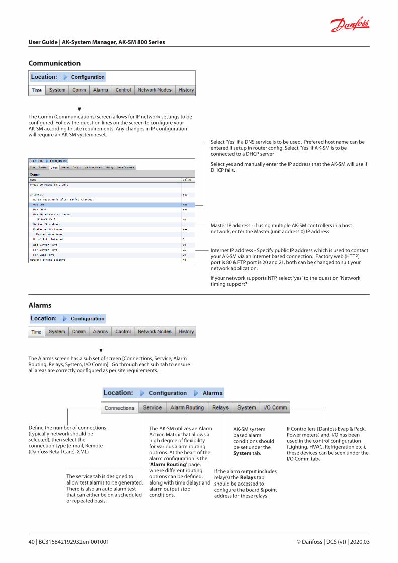
User Guide | AK-System Manager, AK-SM 800 Series
40 | BC316842192932en-001001 © Danfoss | DCS (vt) | 2020.03
Alarms
Communication
Internet IP address - Specify public IP address which is used to contact your AK-SM via an Internet based connection. Factory web (HTTP) port is 80 & FTP port is 20 and 21, both can be changed to suit your network application.
If your network supports NTP, select ‘yes’ to the question ‘Network timing support?’
Select ‘Yes’ if a DNS service is to be used. Prefered host name can be entered if setup in router config. Select ‘Yes’ if AK-SM is to be connected to a DHCP server
Select yes and manually enter the IP address that the AK-SM will use if DHCP fails.
The Comm (Communications) screen allows for IP network settings to be configured. Follow the question lines on the screen to configure your AK-SM according to site requirements. Any changes in IP configuration will require an AK-SM system reset.
Master IP address - if using multiple AK-SM controllers in a host network, enter the Master (unit address 0) IP address
Define the number of connections (typically network should be selected), then select the connection type [e-mail, Remote (Danfoss Retail Care), XML)
The service tab is designed to allow test alarms to be generated. There is also an auto alarm test that can either be on a scheduled or repeated basis.
The Alarms screen has a sub set of screen [Connections, Service, Alarm Routing, Relays, System, I/O Comm]. Go through each sub tab to ensure all areas are correctly configured as per site requirements.
The AK-SM utilizes an Alarm Action Matrix that allows a high degree of flexibility for various alarm routing options. At the heart of the alarm configuration is the ‘Alarm Routing’ page, where different routing options can be defined, along with time delays and alarm output stop conditions.
If the alarm output includes relay(s) the Relays tab should be accessed to configure the board & point address for these relays
AK-SM system based alarm conditions should be set under the System tab.
If Controllers (Danfoss Evap & Pack, Power meters) and, I/O has been used in the control configuration (Lighting, HVAC, Refrigeration etc.), these devices can be seen under the I/O Comm tab.

User Guide | AK-System Manager, AK-SM 800 Series
© Danfoss | DCS (vt) | 2020.03 BC316842192932en-001001 | 41
Connections screen - Define the number of connections, then select the connection type. Your AK-SM can offer the following alarm IP based alarm output;
e-mail, Remote (Danfoss Electronic delivered services) and XML. Depending on your configuration the screen will reflect the required inputs in order to satisfy the output. In order for any alarms to be routed out of your AK-SM please ensure a schedule is configured. Failure to set a schedule will inhibit any alarm output.
Ensure a schedule is defined to allow alarm ouput
To configure a netwrok connection select ‘Number of network connections’
Type (e-mail | Remote | XML)
Enter valid server name (or IP) for e-mail serverIf your e-mail service requires user authorization, enter user name and passwordNote: SSL is not supported
Send to: Add the e-mail address for intended recipients
Reply to:
A mandatory field that must have a valid entry (address with same domain name). An abbreviated message would have reduced text in the alarm message
Configure a schedule to enable the alarm e-mail output
Example of e-mail configuration
4G Wireless routers
4G technology offers many benefits over standard dial up connections. Utilizing a 4G connection the full range of AK-SM services can be used, including web browser, and RMT. Where Internet / Intranet connection is not available, Danfoss recommends considering 4G as a means of offering IP connectivity. Please consult your local Danfoss sales office with regard to 4G connectivity.
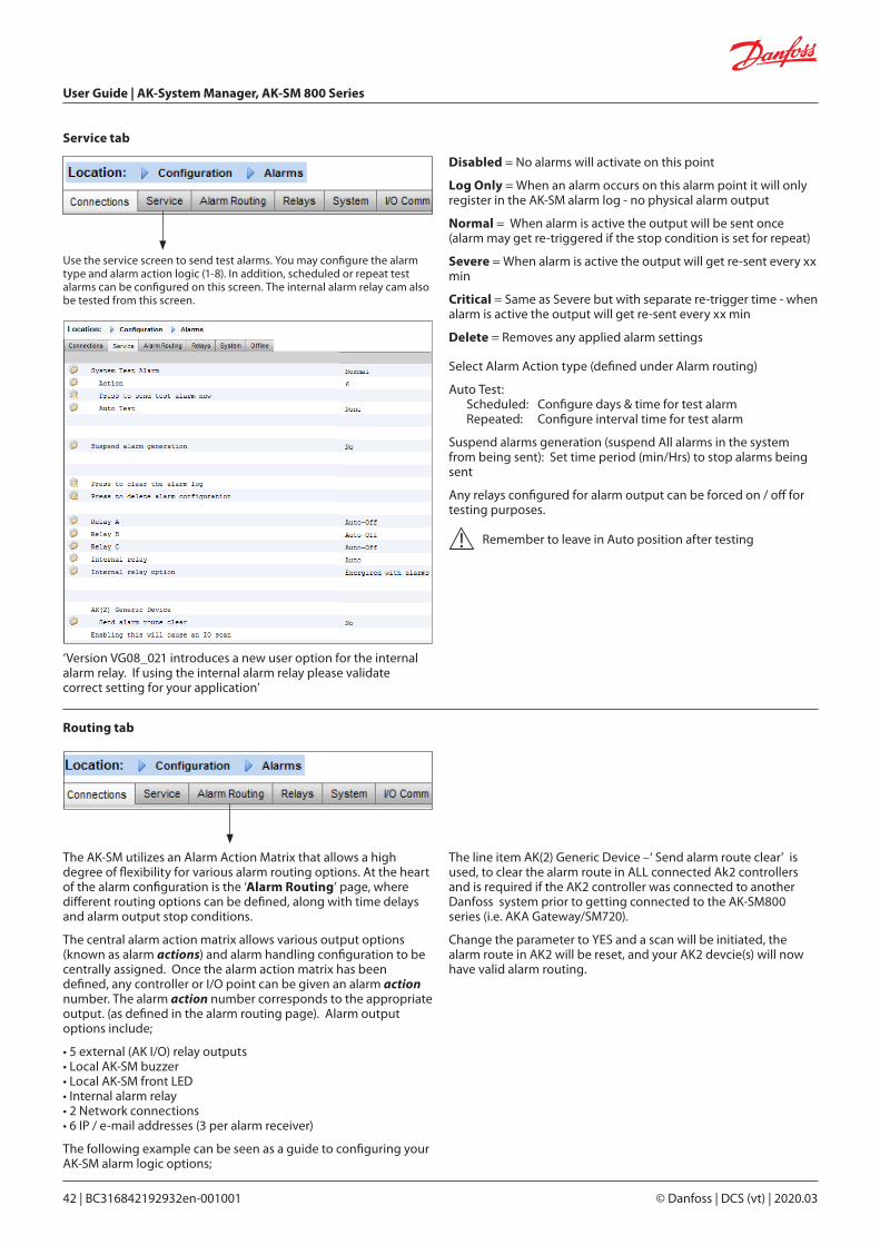
User Guide | AK-System Manager, AK-SM 800 Series
42 | BC316842192932en-001001 © Danfoss | DCS (vt) | 2020.03
Service tab
Disabled = No alarms will activate on this point
Log Only = When an alarm occurs on this alarm point it will only register in the AK-SM alarm log - no physical alarm output
Normal = When alarm is active the output will be sent once (alarm may get re-triggered if the stop condition is set for repeat)
Severe = When alarm is active the output will get re-sent every xx min
Critical = Same as Severe but with separate re-trigger time - when alarm is active the output will get re-sent every xx min
Delete = Removes any applied alarm settings
Use the service screen to send test alarms. You may configure the alarm type and alarm action logic (1-8). In addition, scheduled or repeat test alarms can be configured on this screen. The internal alarm relay cam also be tested from this screen.
Select Alarm Action type (defined under Alarm routing)
Auto Test: Scheduled: Configure days & time for test alarm Repeated: Configure interval time for test alarm
Suspend alarms generation (suspend All alarms in the system from being sent): Set time period (min/Hrs) to stop alarms being sent
Any relays configured for alarm output can be forced on / off for testing purposes.
Remember to leave in Auto position after testing
The AK-SM utilizes an Alarm Action Matrix that allows a high degree of flexibility for various alarm routing options. At the heart of the alarm configuration is the ‘Alarm Routing’ page, where different routing options can be defined, along with time delays and alarm output stop conditions.
The central alarm action matrix allows various output options (known as alarm actions) and alarm handling configuration to be centrally assigned. Once the alarm action matrix has been defined, any controller or I/O point can be given an alarm action number. The alarm action number corresponds to the appropriate output. (as defined in the alarm routing page). Alarm output options include;
• 5 external (AK I/O) relay outputs• Local AK-SM buzzer• Local AK-SM front LED• Internal alarm relay• 2 Network connections• 6 IP / e-mail addresses (3 per alarm receiver)
The following example can be seen as a guide to configuring your AK-SM alarm logic options;
Routing tab
‘Version VG08_021 introduces a new user option for the internal alarm relay. If using the internal alarm relay please validate correct setting for your application’
The line item AK(2) Generic Device –‘ Send alarm route clear’ is used, to clear the alarm route in ALL connected Ak2 controllers and is required if the AK2 controller was connected to another Danfoss system prior to getting connected to the AK-SM800 series (i.e. AKA Gateway/SM720).
Change the parameter to YES and a scan will be initiated, the alarm route in AK2 will be reset, and your AK2 devcie(s) will now have valid alarm routing.

User Guide | AK-System Manager, AK-SM 800 Series
© Danfoss | DCS (vt) | 2020.03 BC316842192932en-001001 | 43
To configure an alarm action, navigate to the required output line (I.E. Relay A) and press enter. The resulting screen allows the configuration of the alarm actions, any pre delays, duration times and stop conditions. The results of this configuration will be shown in the alarm routing page.
Component Column (alarm output)
Select from the options seen in this column;• Relay A-E• Front LED• Buzzer• Int. Relay • Network 1• Network 2
Alarm Actions (1-8)Up to 8 alarm actions can be defined. Each alarm action can have multiple outputs, making the AK-SM alarm output options very flexible. ‘Look down’ each alarm action number column and any associated outputs will be seen in the left hand column
DelayOnce an alarm action is defined theassociated time delay for the action can beset. This delay is in addition to any delay already defined in any controller (i.e. EKC) ormonitoring points (i.e. I/O) defined in the system.
DurationA duration time is available when eitherTime or Time/Repeat are selected as stopconditions. The duration setting definesthe length of time the alarm output will beactive for (irrespective if the alarm is stillactive or acknowledged or not)Available in second or minute selections. 0 Sec/Min duration will result in the alarm output remaining off.Min = 0 Sec/MinMax = 99 Sec/Min
StopThe stop condition defines when the alarm output will stop or return to configuredposition. The following definitions apply;Time = Stop on time (set under duration)Ack = Stop on alarm being acknowledgedClear = Stop when alarm clearsTime/Rep = Stop after time delay but repeat if alarm is still activeAck/Rep = Stop after alarm is acknowledged. If alarm stillactive after acknowledge repeat alarm action (repeat
Custom text that better reflects the alarm relays can
be entered. Use the ‘component name
display’ to toggle between custom text & factory name
(Relay A, Relay B...)
Alarm Actions (1-8)Each alarm action can have multiple relays, IP address, etc assigned
Delays & Stop conditions Set pre delay, duration and stop conditions (for each alarm output selection)
Alarm output optionsSelect the appropriate‘component’ (i.e relay,
network) and configure by double clicking on the
appropriate line

User Guide | AK-System Manager, AK-SM 800 Series
44 | BC316842192932en-001001 © Danfoss | DCS (vt) | 2020.03
Example configuration
This example will describe the steps to configure an alarm actions. Alarm action 1 will be defined according to the following;
• Relay A should trigger after a 10 second pre delay. This relay will energize any time and will only reset when the alarm clears.
• The Front LED should activate (de-activate LED when alarm clears)
• The Buzzer should only activate during the Day (Buzzer stops when alarm is Acknowledged)
• Alarm message should also be sent out via e-mail
The above alarm outputs are associated with action 1 - ‘look down’ the alarm action 1 column and the relevant outputs can be seen in the left of the page.
Action settings:Once in the actual output page, navigate through the lines and set the relevant Action. Each action can have the following settings;
Not Selected: No action
Enabled: Will enable this output action (any time of day)
Day: Enable this output during day status (based on store opening times (ConfigurationTime)
Night: Enable this output during night status (based on time outside of store opening times (ConfigurationTime)
Delay, Units & Stop settings:To complete the output configuration set the time delay, units & stop conditions should be set. Stop conditions;
Time = Stop on time (set under duration)Ack = Stop on alarm being acknowledgedClear = Stop when alarm clearsTime/Rep = Stop after time delay but repeat if alarm is still activeAck/Rep = Stop after alarm is acknowledged. If alarm still activeactive after acknowledge repeat
To define the alarm output options navigate down the page and double click the relevant line.
This opens another page that allows the configuration for that output to be set. In the example below Relay A and the Buzzer can be seen. Follow the same process for the other outputs. For e-mail output, navigate to the Network 1 line and press enter. Here, set the action, time delay & stop conditions. (The actual e-mail configuration is done in the Alarm ‘Connections’ page).
The results of the alarm output configuration can be seen in the central Alarm Routing page. Follow this process for other actions.
Relay A Configuration page
‘Look down’ Alarm action 1 column

User Guide | AK-System Manager, AK-SM 800 Series
© Danfoss | DCS (vt) | 2020.03 BC316842192932en-001001 | 45
Relay tab
If the alarm output includes relay(s) the Relays tab should be accessed to configure the board & point address for these relays. The example below shows relay A & C, with the associated (AK I/O) board & point address.
Enter the AK I/O board & point location for the relay(s)
Select N-Open / N-Closed as required
AK-SM system based alarm conditions should be set under the System tab. The alarms seen in this page are factory set but can be changed as per site requirements. Navigate down each line and configure (pressing the enter key) as required. The following items can be seen and changed under the System tab;
I/O Network Fail: Alarm if communications to AK I/O failsFlash Memory fail: Alarm if AK-SM system memory failsDatabase Cleared: Alarm if AK-SM database is clearedFile Error: Alarm if critical files do not load / not present on AK-SM system (I.E. Device list missing)Alarm send fail: Alarm if any active alarms were unable to be sent outNTP Failure: Alarm if the network time protocol failsHost Comm: Alarm If host communication fails Host Count: Alarm if one or more AK-SM units disconnect from host netwokRam Disk Full: Alert alarm if Ram is getting full (due to EDF files)
System tab
Factory settings can be changed as per customer requirements.
Alarm level & Actions can be changed

User Guide | AK-System Manager, AK-SM 800 Series
46 | BC316842192932en-001001 © Danfoss | DCS (vt) | 2020.03
If Controllers (Danfoss Evap & Pack, Power meters) and, I/O has been used in the control configuration (Lighting, HVAC, Refrigeration etc.), these devices can be seen under the I/O Comm tab.
The I/O Comm tab allows any offline communication alarms to be configured. The example below shows an evaporator controller (address 1) with the alarm level set to ‘Normal’ & alarm action ‘1’. These factory settings can be changed in this page.
I/O Comm tab
Any AK I/O points used in the AK-SM system can be found on this page, with the associated alarm level and actions set. The factory settings can be changed as required.
Calculations & OtherIf any calculations have been defined in the AK-SM system, alarms can be associated with these. Use the Calculations tab to set appropriate alarm levels and actions.
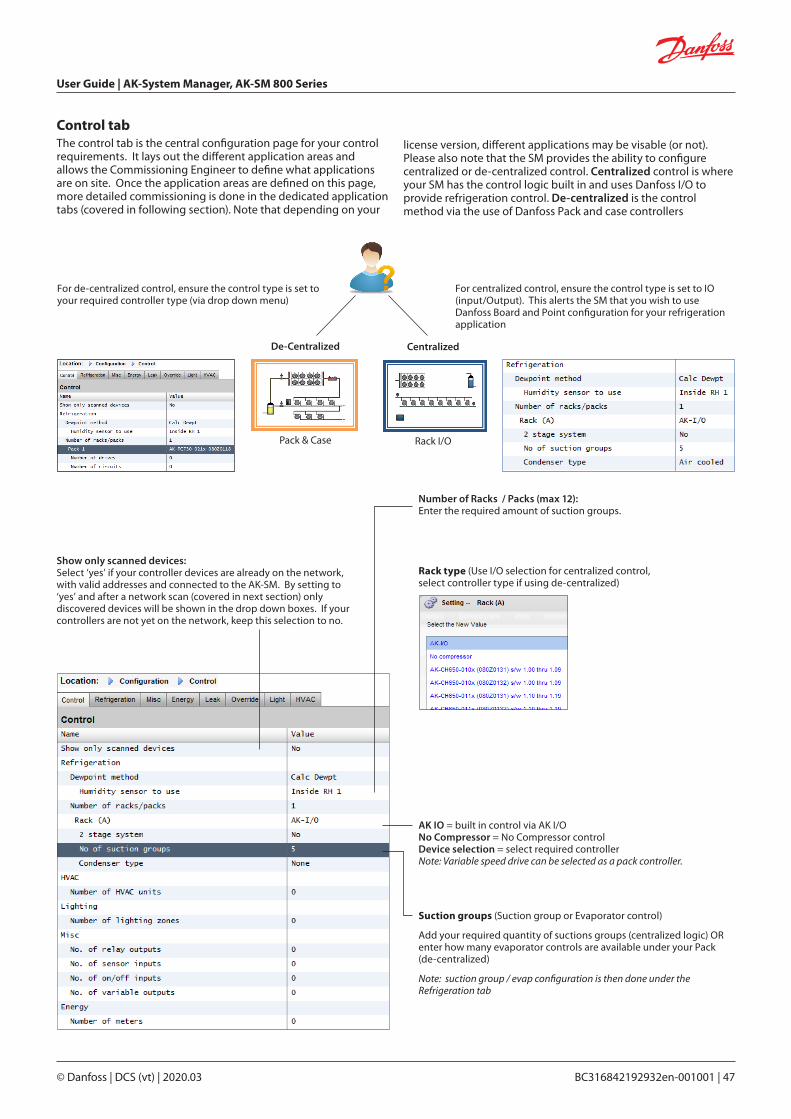
User Guide | AK-System Manager, AK-SM 800 Series
© Danfoss | DCS (vt) | 2020.03 BC316842192932en-001001 | 47
Control tabThe control tab is the central configuration page for your control requirements. It lays out the different application areas and allows the Commissioning Engineer to define what applications are on site. Once the application areas are defined on this page, more detailed commissioning is done in the dedicated application tabs (covered in following section). Note that depending on your
Show only scanned devices:Select ‘yes’ if your controller devices are already on the network, with valid addresses and connected to the AK-SM. By setting to ‘yes’ and after a network scan (covered in next section) only discovered devices will be shown in the drop down boxes. If your controllers are not yet on the network, keep this selection to no.
Number of Racks / Packs (max 12):Enter the required amount of suction groups.
Rack type (Use I/O selection for centralized control, select controller type if using de-centralized)
AK IO = built in control via AK I/ONo Compressor = No Compressor controlDevice selection = select required controllerNote: Variable speed drive can be selected as a pack controller.
Suction groups (Suction group or Evaporator control)
Add your required quantity of suctions groups (centralized logic) OR enter how many evaporator controls are available under your Pack (de-centralized)
Note: suction group / evap configuration is then done under the Refrigeration tab
CentralizedDe-Centralized
Pack & Case Rack I/O
For centralized control, ensure the control type is set to IO (input/Output). This alerts the SM that you wish to use Danfoss Board and Point configuration for your refrigeration application
For de-centralized control, ensure the control type is set to your required controller type (via drop down menu)
license version, different applications may be visable (or not). Please also note that the SM provides the ability to configure centralized or de-centralized control. Centralized control is where your SM has the control logic built in and uses Danfoss I/O to provide refrigeration control. De-centralized is the control method via the use of Danfoss Pack and case controllers

User Guide | AK-System Manager, AK-SM 800 Series
48 | BC316842192932en-001001 © Danfoss | DCS (vt) | 2020.03
The following screen shots below represent an example of de-centralized configuration (Pack and Case control).
The AK-SM has been configured for two pack controllers (AK-PC 730 and the AK-PC 840), with 5 Evaporator controllers under each pack. Selection for each Pack controller was made via the pop up box that appears when the Rack line is double clicked.
First, navigate to the ‘Address’ tab. Enter a valid network address, corresponding to the address already set in the field controllers.
Note: If your field controllers have already been configured with the relevant parameters set, you may wish to perform an ‘Upload’. This function forces the AK-SM to pull back the controller settings and thus synchronize the AK-SM database. Only use the ‘Download’ function if you have finished controller configuration on the AK-SM and you wish then to send these settings ‘down’ to the controller.
A one click option for this (upload/download) can be found under the ConfigurationNetwork Nodes tab
Set a custom name for your control devices
Enter address that matches the physical address in the pack and case controllers
Double click to select your required Pack device
Once the Pack controllers have been defined and the number of case controllers under each pack have been set, continue to the Refrigeration tab for detailed configuration.
See above note about Download / Upload
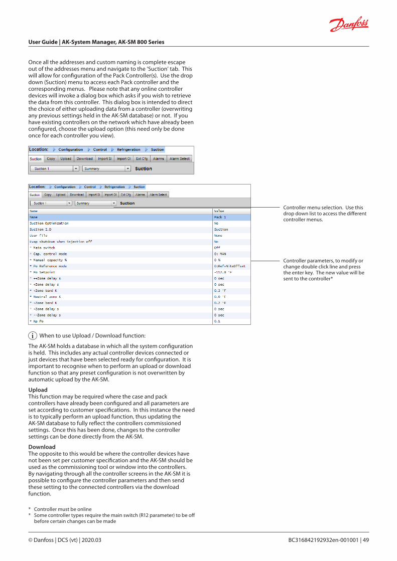
User Guide | AK-System Manager, AK-SM 800 Series
© Danfoss | DCS (vt) | 2020.03 BC316842192932en-001001 | 49
Controller menu selection. Use this drop down list to access the different controller menus.
Once all the addresses and custom naming is complete escape out of the addresses menu and navigate to the ‘Suction’ tab. This will allow for configuration of the Pack Controller(s). Use the drop down (Suction) menu to access each Pack controller and the corresponding menus. Please note that any online controller devices will invoke a dialog box which asks if you wish to retrieve the data from this controller. This dialog box is intended to direct the choice of either uploading data from a controller (overwriting any previous settings held in the AK-SM database) or not. If you have existing controllers on the network which have already been configured, choose the upload option (this need only be done once for each controller you view).
When to use Upload / Download function:
The AK-SM holds a database in which all the system configuration is held. This includes any actual controller devices connected or just devices that have been selected ready for configuration. It is important to recognise when to perform an upload or download function so that any preset configuration is not overwritten by automatic upload by the AK-SM.
UploadThis function may be required where the case and pack controllers have already been configured and all parameters are set according to customer specifications. In this instance the need is to typically perform an upload function, thus updating the AK-SM database to fully reflect the controllers commissioned settings. Once this has been done, changes to the controller settings can be done directly from the AK-SM.
DownloadThe opposite to this would be where the controller devices have not been set per customer specification and the AK-SM should be used as the commissioning tool or window into the controllers. By navigating through all the controller screens in the AK-SM it is possible to configure the controller parameters and then send these setting to the connected controllers via the download function.
* Controller must be online* Some controller types require the main switch (R12 parameter) to be off
before certain changes can be made
Controller parameters, to modify or change double click line and press the enter key. The new value will be sent to the controller*
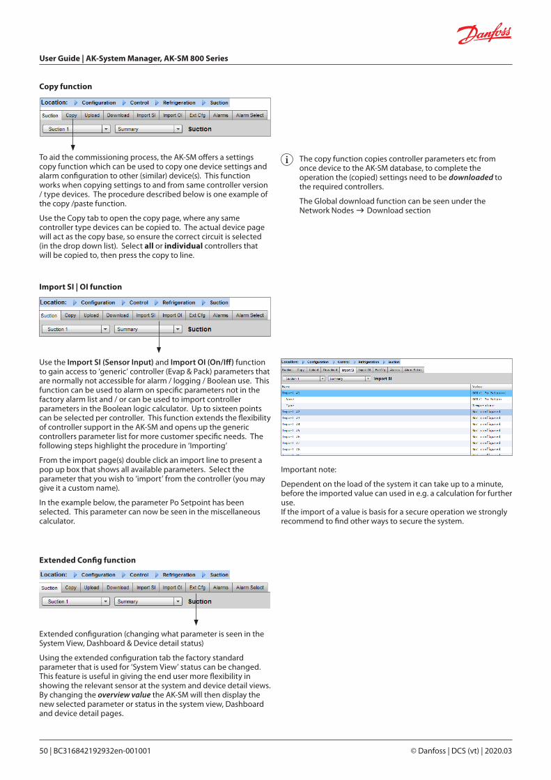
User Guide | AK-System Manager, AK-SM 800 Series
50 | BC316842192932en-001001 © Danfoss | DCS (vt) | 2020.03
To aid the commissioning process, the AK-SM offers a settings copy function which can be used to copy one device settings and alarm configuration to other (similar) device(s). This function works when copying settings to and from same controller version / type devices. The procedure described below is one example of the copy /paste function.
Use the Copy tab to open the copy page, where any same controller type devices can be copied to. The actual device page will act as the copy base, so ensure the correct circuit is selected (in the drop down list). Select all or individual controllers that will be copied to, then press the copy to line.
Copy function
Use the Import SI (Sensor Input) and Import OI (On/Iff) function to gain access to ‘generic’ controller (Evap & Pack) parameters that are normally not accessible for alarm / logging / Boolean use. This function can be used to alarm on specific parameters not in the factory alarm list and / or can be used to import controller parameters in the Boolean logic calculator. Up to sixteen points can be selected per controller. This function extends the flexibility of controller support in the AK-SM and opens up the generic controllers parameter list for more customer specific needs. The following steps highlight the procedure in ‘Importing’
From the import page(s) double click an import line to present a pop up box that shows all available parameters. Select the parameter that you wish to ‘import’ from the controller (you may give it a custom name).
In the example below, the parameter Po Setpoint has been selected. This parameter can now be seen in the miscellaneous calculator.
Import SI | OI function
The copy function copies controller parameters etc from once device to the AK-SM database, to complete the operation the (copied) settings need to be downloaded to the required controllers.
The Global download function can be seen under the Network Nodes Download section
Extended configuration (changing what parameter is seen in the System View, Dashboard & Device detail status)
Using the extended configuration tab the factory standard parameter that is used for ‘System View’ status can be changed. This feature is useful in giving the end user more flexibility in showing the relevant sensor at the system and device detail views. By changing the overview value the AK-SM will then display the new selected parameter or status in the system view, Dashboard and device detail pages.
Extended Config function
Important note:
Dependent on the load of the system it can take up to a minute, before the imported value can used in e.g. a calculation for further use.If the import of a value is basis for a secure operation we strongly recommend to find other ways to secure the system.

User Guide | AK-System Manager, AK-SM 800 Series
© Danfoss | DCS (vt) | 2020.03 BC316842192932en-001001 | 51
Use the Alarm tab to define the alarm actions associated with this device. Use the Alarm select tab to select up to 300 alarm points (max 300 per AK-PC controller)
Alarms and Alarm Select
Configuration HISTORY
The AK-SM history section allows the collection and recording of control parameters, values and status. The central history function allows up to 600 ‘points’ to be configured, a point being a temperature, pressure, status, relay, etc. The collection of history allows further analysis using the AK-SM or remote web browser, where a graphical representation of this data can be made.
To configure history, navigate to the Setup tab (ConfigurationHistory). The following setup lines are visible;
Auto Configure History: Use this function to auto select typical points needed for logging (the AK-SM will select key points in the Refrigeration, HVAC, Lighting and Misc control areas. Manual configuration can be done to override these selections or add more as required.
Clear History Configuration: Use this function to clear history configuration (points selected for history & the frequency of samples)
Clear History log: Use this function to clear stored history in the AK-SM
Start / Suspend History: Once the relevant points have been selected for history collection (using either the Auto history, manual or a combination of both) press this line to Start the collection. Press again to Stop collection
Status: Displays the current status of history collection (Collecting or Suspended)
No of Configured datapoints: Displays the number of configured history points (max 600)
Note: Ensure the correct time & date are set in the AK-SM. Make sure the history collection function is running to ensure the collection of datapoints. Use the ‘Start History’ line and check that the status reflects ‘Collecting’.
When assigning history points to a controller device a recommended max of 45 points per device is allowed. Assigning more than 45 points per device will cause points not to record log history.
Auto Configure HistoryWhen selecting the auto configure history function the AK-SM presents the option to select the history collection sample rate.These can be later changed & modified under the relevant history device type (Controllers/Relays/Sensors/On/Off/Variable/Other)
A change of the log interval will delete all previous logs of that chosen data point.
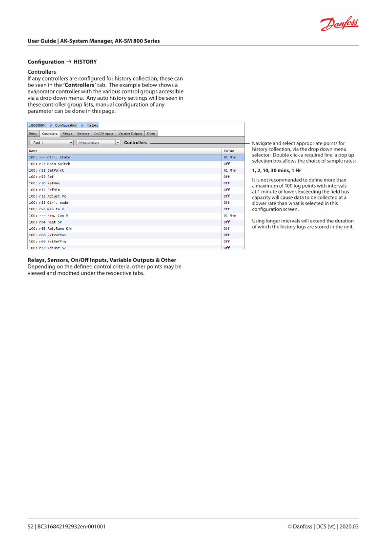
User Guide | AK-System Manager, AK-SM 800 Series
52 | BC316842192932en-001001 © Danfoss | DCS (vt) | 2020.03
Configuration HISTORY
ControllersIf any controllers are configured for history collection, these can be seen in the ‘Controllers’ tab. The example below shows a evaporator controller with the various control groups accessible via a drop down menu. Any auto history settings will be seen in these controller group lists, manual configuration of any parameter can be done in this page.
Navigate and select appropriate points for history collection, via the drop down menu selector. Double click a required line, a pop up selection box allows the choice of sample rates;
1, 2, 10, 30 mins, 1 Hr
It is not recommended to define more thana maximum of 100 log points with intervalsat 1 minute or lower. Exceeding the field buscapacity will cause data to be collected at aslower rate than what is selected in thisconfiguration screen.
Using longer intervals will extend the durationof which the history logs are stored in the unit.
Relays, Sensors, On/Off Inputs, Variable Outputs & Other Depending on the defined control criteria, other points may be viewed and modified under the respective tabs.

User Guide | AK-System Manager, AK-SM 800 Series
© Danfoss | DCS (vt) | 2020.03 BC316842192932en-001001 | 53
From the Control screen navigate to Refrigeration then Rail Heat (ConfigurationRefrigerationRail Heat)
(Energy saving features, scheduling and load shedding configuration)
This section will discuss rail heat control, schedules, HVAC, and lighting. Please refer to this section when configuring more advanced areas of your AK-SM.
Rail HeatThe AK-SM can be used to manage the energy output to the case trim heaters (Rail Heat). There are different ways to approach the solution to rail heat control, listed below are three main possibilities.
1. Use a Night Setback Schedule Many Danfoss controls have a function whereby the output to
the rail heat elements can be pulsed in a percentage of time ratio. If set in the controller, the night setback signal from the AK-SM will allow the controller to vary the output depending on the time period. Consult specific controller manual for more details.
2. Use AK I/O relays to control rail heater connections (using ‘Calculated’ or physical Dew point) By means of utilizing temperature and relative humidity
sensors the AK-SM can calculate the relative Dew point. Based on this Dew point reference and against a set point the output to the rail heat elements can be controlled. This represents ‘tighter’ control based on the calculated Dew point.
3. Use Adaptive Rail heat control Adaptive rail heat is a feature that groups together a collection
of compatible evaporator controllers that receive signals of the current calculated dew point from an installed dew point / temperature sensor. The installed humidity / temperature sensor connects to the AK-SM (via I/O) and the resulting calculated dew point value is sent to the connected evaporator controllers.
Chapter 5: Master Control Functions

User Guide | AK-System Manager, AK-SM 800 Series
54 | BC316842192932en-001001 © Danfoss | DCS (vt) | 2020.03
0%
(0 mins)
100%50%(5 mins on)(5 mins off)
-4.0
8.0
90%(9 mins on)(1 min off)
2.0
7.0
Targ
et D
ewp
oint
Ran
ge
Example of Target Dewpoint & relay output % ratio
Relay output percentage (based on cycle time setting)
Example: With a Dew point target range of -4.0 to 8.0°c and the Cycle time set for 10 minutes the following behavior will be true. At -4.0°c Dewpoint the relay output will be 0% At 8.0°c Dewpoint the relay output will be 100% At 2.0°c Dewpoint the relay output will be 50% of the cycle time (5 mins on, 5 mins off) At 7.0°c Dewpoint the relay output will be 90% of the cycle time (9 mins on, 1 min off)
EMHS -3-1 Humidity Sensor (combined Humidity & Temperature): 12V / 24V supply via I/O modules0-5V Relative HumidityTemperature Sensor
AK I/O relay method
Select ‘No’ to the question line ‘Use Adaptive Rail heat’.Define how many relays will be used in the control of the rail heat elements (max 30). Cycle time - Used to determine what amount of time the relays are energized, used in combination with the output percentage as set in the Dew point setpoint.
Dewpoint method - Calculated dewpoint (Using a combined temperature / humidity sensor - type: EMHS3-1 is recommended. See below for wiring example)- Dewpoint (Utilize direct output from dewpoint sensor)
Selecting Use HVAC humidity to “yes” Rail heat dew point will be calculated using Rail Temp and Inside RH sensor inputs. A Rail hum point will not be generated by the SM800.
Selecting Use HVAC humidity to “no” Rail heat dew point will be calculated using Rail Temp and Rail hum sensor inputs.

User Guide | AK-System Manager, AK-SM 800 Series
© Danfoss | DCS (vt) | 2020.03 BC316842192932en-001001 | 55
EMHS3-1 Humidity & Temperature sensor
Rail Heat Relay
AK I/O modules
Controller bus
Calculated Dew point sent to controllers on bus
Rail Heat Relay
01-1.301-1.4
Adaptive method (with compatible Danfoss evaporator controllers)
Adaptive rail heat is a feature that groups together a collection of compatible evaporator controllers that receive signals of the current calculated dew point from an installed dew point / temperature sensor. The installed humidity / temperature sensor connects to the AK-SM (via I/O) and the resulting calculated dew point value is sent to the connected evaporator controllers. By controlling rail heat according to the actual dew point measured in the store, significant energy savings can be achieved. The following section highlights how to configure active rail heat via the Danfoss AK-CC 550 evaporator controller (which has the ability to utilize calculated dew point over the communications bus).
Select ‘Yes’ to the question line ‘Use Adaptive Rail heat’, and (in this example) select ‘Calculated Dewpoint’ as the dewpoint method. Upon answering these questions the AK-SM will automatically build sensor points to allow for the humidity and temperature sensors to be defined. As the diagram below shows, the EMHS3-1 sensor has humidity and temperature wired in to an AK I/O module, the points at which these sensors are connected can then be added under the sensor page (ConfigurationControlRefrigeration-Addresses)
When using the EMHS3-1 sensor the humidity & temperature output will be
connected to AK I/O.Use the ‘Addresses’ tab to locate the sensor
sub- tab, where the appropriate board & point can be set (in line with the physical
connections on the AK I/O)

User Guide | AK-System Manager, AK-SM 800 Series
56 | BC316842192932en-001001 © Danfoss | DCS (vt) | 2020.03
Schedules(used in combination with Danfoss controllers)
ConfigurationControlRefrigerationSchedules
Under the schedules section multiple schedules can be added and configured according to your needs.
Enter the number of schedules required. The desired number of schedules will be shown (in this example 3 schedules have been requested). Initially each new schedule is set to disabled, move the cursor to the required schedule line and press ‘Enter’. The resulting page allows the definition of the schedule, the following configuration settings can be made;
• Enable this schedule (ensure this is set to ‘YES’ to engage schedule)
• Schedule usage (Choose from Case Lighting, Night Setback, Shutdown, Defrost, Coord Defrost)
• Description (Add custom description for schedule)
• Schedule control (Choose between Time, Digital, Time & Digital, Time or Digital)
• Number of schedules (select the number of sub schedules required)
• Start, Stop, Days and Holidays (Define the Start / Stop times, days and holidays)
Each schedule line will also reflect the current status False = schedule not active True = schedule is activeDisabled = Not Active (Enable in schedule setup page)
Rail heat settings in the AK-CC550o85 = Rail heat control (select option 2, pulse control with dew point function)o86 = Dew Point MIN limito87 = Dew point Max limitAt a dew point which is equal to or lower than the value in 086, the effect will be the value indicated in o88. In the area between the two dew point values the controller will manage the power to the rail heat
For adaptive rail heat to function correctly ensure the AK-CC 550 controllers are set correctly. Review parameters o85, o86 and o87, as noted below. The screen image below highlights the AK-CC 550 controller (Miscellanious menu), where parameter o85, o86 and o87 are set for rail heat control over the bus.
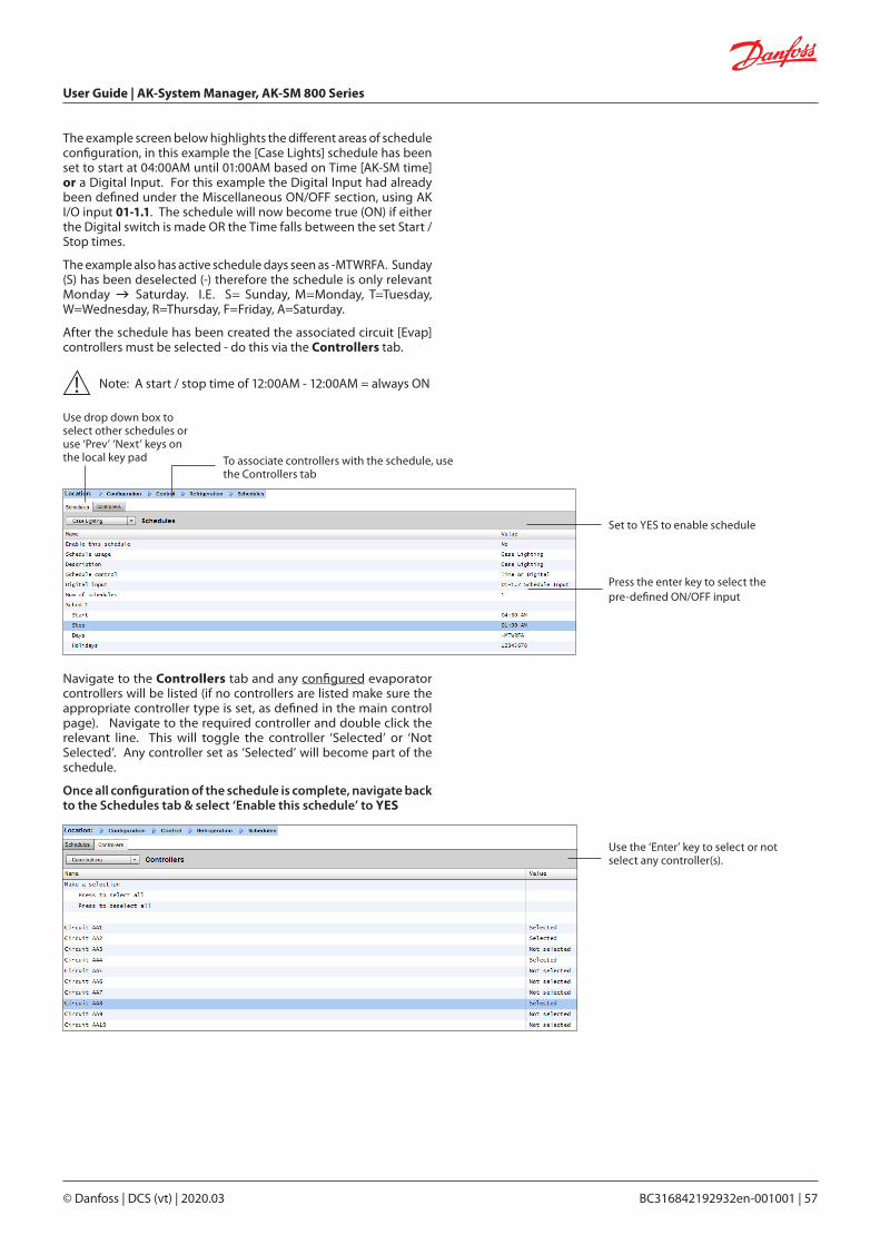
User Guide | AK-System Manager, AK-SM 800 Series
© Danfoss | DCS (vt) | 2020.03 BC316842192932en-001001 | 57
The example screen below highlights the different areas of schedule configuration, in this example the [Case Lights] schedule has been set to start at 04:00AM until 01:00AM based on Time [AK-SM time] or a Digital Input. For this example the Digital Input had already been defined under the Miscellaneous ON/OFF section, using AK I/O input 01-1.1. The schedule will now become true (ON) if either the Digital switch is made OR the Time falls between the set Start / Stop times.
The example also has active schedule days seen as -MTWRFA. Sunday (S) has been deselected (-) therefore the schedule is only relevant Monday Saturday. I.E. S= Sunday, M=Monday, T=Tuesday, W=Wednesday, R=Thursday, F=Friday, A=Saturday.
After the schedule has been created the associated circuit [Evap] controllers must be selected - do this via the Controllers tab.
Note: A start / stop time of 12:00AM - 12:00AM = always ON
Set to YES to enable schedule
Use drop down box to select other schedules or use ‘Prev’ ‘Next’ keys on the local key pad
Press the enter key to select the pre-defined ON/OFF input
To associate controllers with the schedule, use the Controllers tab
Navigate to the Controllers tab and any configured evaporator controllers will be listed (if no controllers are listed make sure the appropriate controller type is set, as defined in the main control page). Navigate to the required controller and double click the relevant line. This will toggle the controller ‘Selected’ or ‘Not Selected’. Any controller set as ‘Selected’ will become part of the schedule.
Once all configuration of the schedule is complete, navigate back to the Schedules tab & select ‘Enable this schedule’ to YES
Use the ‘Enter’ key to select or not select any controller(s).
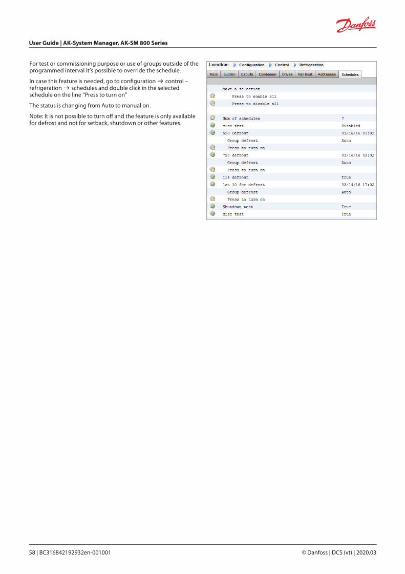
User Guide | AK-System Manager, AK-SM 800 Series
58 | BC316842192932en-001001 © Danfoss | DCS (vt) | 2020.03
For test or commissioning purpose or use of groups outside of the programmed interval it’s possible to override the schedule.
In case this feature is needed, go to configuration control – refrigeration schedules and double click in the selected schedule on the line “Press to turn on”
The status is changing from Auto to manual on.
Note: It is not possible to turn off and the feature is only available for defrost and not for setback, shutdown or other features.
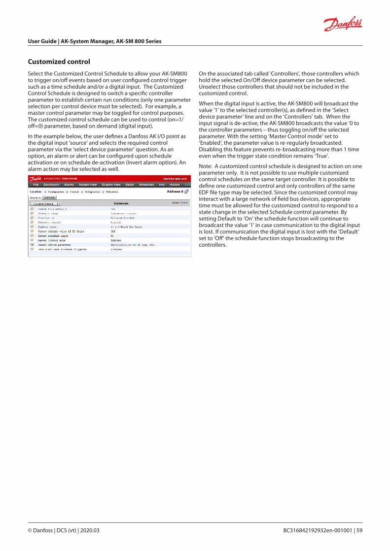
User Guide | AK-System Manager, AK-SM 800 Series
© Danfoss | DCS (vt) | 2020.03 BC316842192932en-001001 | 59
Customized control
Select the Customized Control Schedule to allow your AK-SM800 to trigger on/off events based on user configured control trigger such as a time schedule and/or a digital input. The Customized Control Schedule is designed to switch a specific controller parameter to establish certain run conditions (only one parameter selection per control device must be selected). For example, a master control parameter may be toggled for control purposes. The customized control schedule can be used to control (on=1/off=0) parameter, based on demand (digital input).
In the example below, the user defines a Danfoss AK I/O point as the digital input ‘source’ and selects the required control parameter via the ‘select device parameter’ question. As an option, an alarm or alert can be configured upon schedule activation or on schedule de-activation (Invert alarm option). An alarm action may be selected as well.
On the associated tab called ‘Controllers’, those controllers which hold the selected On/Off device parameter can be selected. Unselect those controllers that should not be included in the customized control.
When the digital input is active, the AK-SM800 will broadcast the value ‘1’ to the selected controller(s), as defined in the ‘Select device parameter’ line and on the ‘Controllers’ tab. When the input signal is de-active, the AK-SM800 broadcasts the value ‘0 to the controller parameters – thus toggling on/off the selected parameter. With the setting ‘Master Control mode’ set to ‘Enabled’, the parameter value is re-regularly broadcasted. Disabling this feature prevents re-broadcasting more than 1 time even when the trigger state condition remains ‘True’.
Note: A customized control schedule is designed to action on one parameter only. It is not possible to use multiple customized control schedules on the same target controller. It is possible to define one customized control and only controllers of the same EDF file type may be selected. Since the customized control may interact with a large network of field bus devices, appropriate time must be allowed for the customized control to respond to a state change in the selected Schedule control parameter. By setting Default to ‘On’ the schedule function will continue to broadcast the value ‘1’ in case communication to the digital input is lost. If communication the digital input is lost with the ‘Default’ set to ‘Off’ the schedule function stops broadcasting to the controllers.

User Guide | AK-System Manager, AK-SM 800 Series
60 | BC316842192932en-001001 © Danfoss | DCS (vt) | 2020.03
Suction Pressure Optimization
The Adaptive Suction Pressure function in your AK-SM makes it possible to automatically optimize the suction pressure so that it will be adapted to the systems actual load. During optimization, data is collected that tells the system which refrigeration appliances are most heavily loaded. This energy saving function can make substantial savings directly whilst also saving on compressor wear and tear and also providing an analysis tool for refrigeration appliances.
The individual controllers handle the temperature control in the refrigeration appliances. The load and operating conditions of each are continuously collected by the AK-SM via the data communication system. The collected data is computed and the “most heavily loaded” refrigeration points are identified.
An adaptation can now be made of the Suction Pressure, whilst ensuring the air temperature at the refrigeration appliance is maintained. It is the AK-SM that collects data from the refrigeration appliances and it is the AK-SM that transmits any offset to the compressor pack control so that suction pressure reference is changed to suit the needs of the “most heavily loaded” refrigeration point. It is always the temperature at the appliance that takes top priority and in fact the suction pressure can float down if necessary.
The time during which a refrigeration point has been designated “the most heavily loaded” will be summed up in the log (history) within the AK-SM.
The pack suction (Po) pressure is optimized in accordance with the current refrigeration demand, taking into account short-term changes (day/night setback/defrost) and long-term effects (seasonal/weather changes).
In order to get the best efficiency out of the Po Optimization function it is highly recommended that a plant survey is done before enabling this function. A poorly running site will not be corrected by Po Optimization and the maximum benefits will not be seen - ensure all plant & evaporator cases are running close to their designed setpoints and that defrost are operating correctly. Also ensure any manual plant override systems are set accordingly to allow the floating up of suction pressure.
It is highly recommended to always use the latest firmware available at http://SM800.danfoss.com.
Theory of operationThe Po Optimize function uses a calculation on all controllers to determine a “Load Factor”. This has been developed by Danfoss
and is available in your AK-SM. By use of the Load Factor the Most Loaded Case (MLC) is constantly updated.
Floating of the Suction Setpoint is then determined at any given time by the MLC
1. The AK-SM continuously receives operating information from each (Po enabled) controller connected on the network. The AK-SM is looking for the 'Most loaded case' (MLC). Each evaporator is analyzed to see if it's current operating temperature is within a calculated MLC 'target window'. During defrost and including after defrost recovery, the Po Optimization will temporarily remove the case from the Po calculation loop. This ensures that normal system fluctuations (due to defrost etc) do not effect the overall operation of Po Optimization.
2. In effect the continuous Po Optimization is looking for the evaporator that is under the heaviest load (the one that has to work the hardest to maintain temperature), but still falls within the MLC target 'window'
3. Based on the MLC the Po optimization function will then send a control signal to the Pack controller to optimize the running suction pressure, i.e. float the pressure up (based on the max limit set in the Pack configuration page). As the Pack controller allows the suction pressure to increase the AK-SM monitors the complete network and ensures that the refrigerating system as a whole is stable. This then is a continuous function that once set runs automatically and ensures the refrigeration system is running to the best conditions.
This feature is available on all supported AK-SM Evap & Pack controllers.
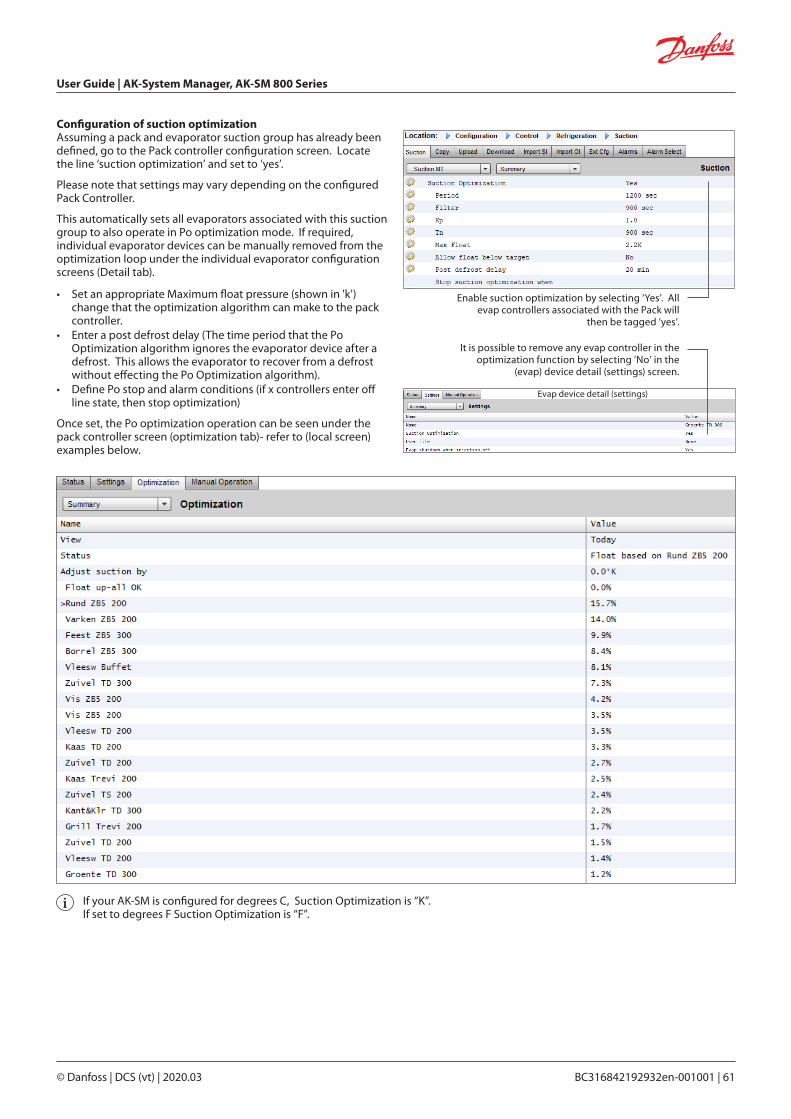
User Guide | AK-System Manager, AK-SM 800 Series
© Danfoss | DCS (vt) | 2020.03 BC316842192932en-001001 | 61
Configuration of suction optimizationAssuming a pack and evaporator suction group has already been defined, go to the Pack controller configuration screen. Locate the line ‘suction optimization’ and set to ‘yes’.
Please note that settings may vary depending on the configured Pack Controller.
This automatically sets all evaporators associated with this suction group to also operate in Po optimization mode. If required, individual evaporator devices can be manually removed from the optimization loop under the individual evaporator configuration screens (Detail tab).
• Set an appropriate Maximum float pressure (shown in 'k') change that the optimization algorithm can make to the pack controller.
• Enter a post defrost delay (The time period that the Po Optimization algorithm ignores the evaporator device after a defrost. This allows the evaporator to recover from a defrost without effecting the Po Optimization algorithm).
• Define Po stop and alarm conditions (if x controllers enter off line state, then stop optimization)
Once set, the Po optimization operation can be seen under the pack controller screen (optimization tab)- refer to (local screen) examples below.
If your AK-SM is configured for degrees C, Suction Optimization is “K”. If set to degrees F Suction Optimization is “F”.
Enable suction optimization by selecting ‘Yes’. All evap controllers associated with the Pack will
then be tagged ‘yes’.
It is possible to remove any evap controller in the optimization function by selecting ‘No’ in the
(evap) device detail (settings) screen.
Evap device detail (settings)
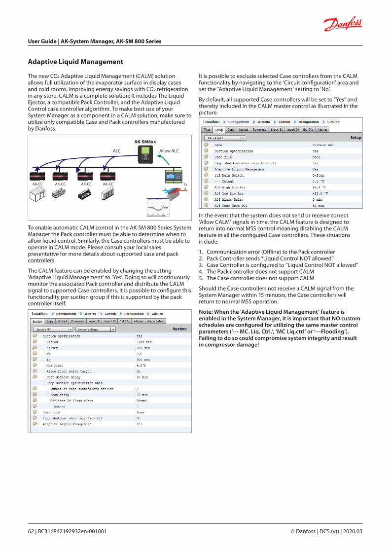
User Guide | AK-System Manager, AK-SM 800 Series
62 | BC316842192932en-001001 © Danfoss | DCS (vt) | 2020.03
The new CO2 Adaptive Liquid Management (CALM) solution allows full utilization of the evaporator surface in display cases and cold rooms, improving energy savings with CO2 refrigeration in any store. CALM is a complete solution: It includes The Liquid Ejector, a compatible Pack Controller, and the Adaptive Liquid Control case controller algorithm. To make best use of your System Manager as a component in a CALM solution, make sure to utilize only compatible Case and Pack controllers manufactured by Danfoss.
To enable automatic CALM control in the AK-SM 800 Series System Manager the Pack controller must be able to determine when to allow liquid control. Similarly, the Case controllers must be able to operate in CALM mode. Please consult your local sales presentative for more details about supported case and pack controllers.
The CALM feature can be enabled by changing the setting ‘Adaptive Liquid Management’ to ‘Yes’. Doing so will continuously monitor the associated Pack controller and distribute the CALM signal to supported Case controllers. It is possible to configure this functionality per suction group if this is supported by the pack controller itself.
Adaptive Liquid Management
It is possible to exclude selected Case controllers from the CALM functionality by navigating to the ‘Circuit configuration’ area and set the “Adaptive Liquid Management’ setting to ‘No’.
By default, all supported Case controllers will be set to “Yes” and thereby included in the CALM master control as illustrated in the picture.
In the event that the system does not send or receive correct ‘Allow CALM’ signals in time, the CALM feature is designed to return into normal MSS control meaning disabling the CALM feature in all the configured Case controllers. These situations include:
1. Communication error (Offline) to the Pack controller2. Pack Controller sends “Liquid Control NOT allowed”3. Case Controller is configured to “Liquid Control NOT allowed” 4. The Pack controller does not support CALM5. The Case controller does not support CALM
Should the Case controllers not receive a CALM signal from the System Manager within 15 minutes, the Case controllers will return to normal MSS operation.
Note: When the ‘Adaptive Liquid Management’ feature is enabled in the System Manager, it is important that NO custom schedules are configured for utilizing the same master control parameters (‘--- MC. Liq. Ctrl.’, ‘MC Liq.ctrl’ or ‘---Flooding’). Failing to do so could compromise system integrity and result in compressor damage!
ALC Allow ALC
AK-SM8xx
AK-CC AK-CC AK-CC AK-CC Pc

User Guide | AK-System Manager, AK-SM 800 Series
© Danfoss | DCS (vt) | 2020.03 BC316842192932en-001001 | 63
AKC ON (Evap shutdown when injection off)
One of the main features of the AKC On function is that the SM will detect if there is a pack shutdown condition. The SM does this by monitoring the pack controller for such conditions. If configured to do so, and upon detecting a pack shut down, the SM will issue a signal to all (configured) evap controllers under the pack suction group to close their AKV valves. The effect of closing the local AKV valve is to limit liquid flow in the evaporator. Due to the AKV valve being closed during a pack shutdown period there is a greatly reduced risk of liquid hammer or compressor damage upon pack / compressor start up. The AKC ON function must be configured for each pack suction group. By default, the associated evap controllers are set to ‘yes’ under the selection choice of Evap shutdown when injection off. If a evap controller is not required to be part of the suction group AKC ON function, set this value to ‘No’. Pack Configuration
Under the settings / Summary screen set the questionEvap shutdown when injection off to ‘YES’
AKC injection ON
For commissioning, retrofit and filter change mode it is necessary to simulate the signal from pack controller. Means, close valves manually.In case the menu “Evap shutdown when injection off” a new menu appears in manual operation section, which enables the user to select between injection ON, OFF and AUTO mode.
Evap Configuration
If the Evap is not required to be part of the AKC ON function, modify the questionEvap shutdown when injection off to ‘No’
Note: make sure that the Pack controller has the field Ctrl. Of Injection ON set to Network, for AK2 style devices you may need the Danfoss Service Tool in order to see this parameter
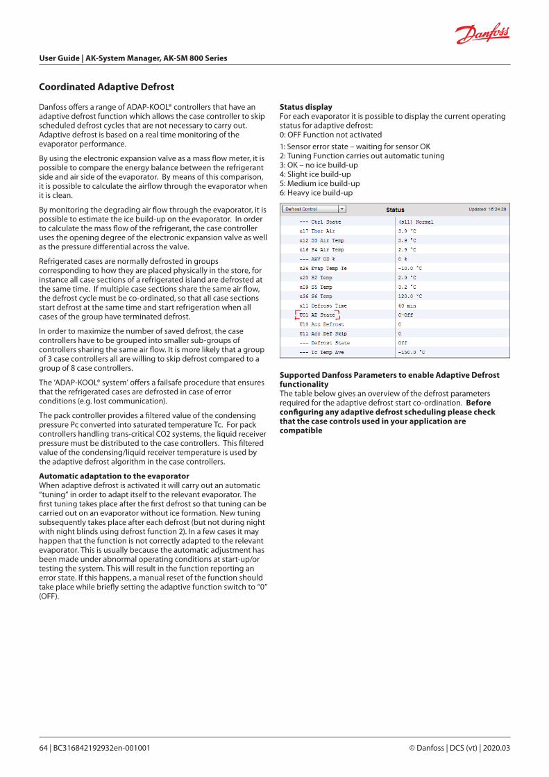
User Guide | AK-System Manager, AK-SM 800 Series
64 | BC316842192932en-001001 © Danfoss | DCS (vt) | 2020.03
Coordinated Adaptive Defrost
Danfoss offers a range of ADAP-KOOL® controllers that have an adaptive defrost function which allows the case controller to skip scheduled defrost cycles that are not necessary to carry out. Adaptive defrost is based on a real time monitoring of the evaporator performance.
By using the electronic expansion valve as a mass flow meter, it is possible to compare the energy balance between the refrigerant side and air side of the evaporator. By means of this comparison, it is possible to calculate the airflow through the evaporator when it is clean.
By monitoring the degrading air flow through the evaporator, it is possible to estimate the ice build-up on the evaporator. In order to calculate the mass flow of the refrigerant, the case controller uses the opening degree of the electronic expansion valve as well as the pressure differential across the valve.
Refrigerated cases are normally defrosted in groups corresponding to how they are placed physically in the store, for instance all case sections of a refrigerated island are defrosted at the same time. If multiple case sections share the same air flow, the defrost cycle must be co-ordinated, so that all case sections start defrost at the same time and start refrigeration when all cases of the group have terminated defrost.
In order to maximize the number of saved defrost, the case controllers have to be grouped into smaller sub-groups of controllers sharing the same air flow. It is more likely that a group of 3 case controllers all are willing to skip defrost compared to a group of 8 case controllers.
The ‘ADAP-KOOL® system’ offers a failsafe procedure that ensures that the refrigerated cases are defrosted in case of error conditions (e.g. lost communication).
The pack controller provides a filtered value of the condensing pressure Pc converted into saturated temperature Tc. For pack controllers handling trans-critical CO2 systems, the liquid receiver pressure must be distributed to the case controllers. This filtered value of the condensing/liquid receiver temperature is used by the adaptive defrost algorithm in the case controllers.
Automatic adaptation to the evaporator When adaptive defrost is activated it will carry out an automatic “tuning” in order to adapt itself to the relevant evaporator. The first tuning takes place after the first defrost so that tuning can be carried out on an evaporator without ice formation. New tuning subsequently takes place after each defrost (but not during night with night blinds using defrost function 2). In a few cases it may happen that the function is not correctly adapted to the relevant evaporator. This is usually because the automatic adjustment has been made under abnormal operating conditions at start-up/or testing the system. This will result in the function reporting an error state. If this happens, a manual reset of the function should take place while briefly setting the adaptive function switch to “0” (OFF).
Status display For each evaporator it is possible to display the current operating status for adaptive defrost: 0: OFF Function not activated
1: Sensor error state – waiting for sensor OK2: Tuning Function carries out automatic tuning 3: OK – no ice build-up 4: Slight ice build-up 5: Medium ice build-up 6: Heavy ice build-up
Supported Danfoss Parameters to enable Adaptive Defrost functionalityThe table below gives an overview of the defrost parameters required for the adaptive defrost start co-ordination. Before configuring any adaptive defrost scheduling please check that the case controls used in your application are compatible

User Guide | AK-System Manager, AK-SM 800 Series
© Danfoss | DCS (vt) | 2020.03 BC316842192932en-001001 | 65
Managers OverrideConfiguration ControlFrom the Configuration Control menu select the number of managers override required.
Chapter 6: Advanced features and configurations
To configure the override, navigate to the ‘Override’ menu tab and follow the below guidelines
The managers override function allows the authorized user to place Lighting zones and or HVAC units into an override state. The expected implementation for this feature is to provide some mechanical switch in the store managers office or loading bay. The following options can be seen in the configuration of the manager’s override;
Timed Override (Yes/No)YES - The override will last for the time selected in the ‘duration (in
Hours)’ line. The point will return to normal operation after this time has elapsed.
NO - The override will last until it’s switch on the override box is operated a second time
Interrupt enabled (Yes/No)YES - The override can be interrupted by a second operation of
the override switchNO - The override cannot be interrupted, the point will remain in
override status for the duration of the selected time
Override is forLighting – lighting zonesHVAC – HVAC units (requires suitable license)Both – The override is for both Lighting and HVACOther Unit – The override is for a point located on another
AK-SM 800(Host network)
Bluetooth InterfaceOverride for securing wireless BT interface in supported controllers (e.g. AK-CC 55).
Override all zones (Yes/No)YES - All lighting zones will be overriddenNO - One or more lighting zone (see details below) will be overridden
Override all units (Yes/No)YES - All HVAC units will be overriddenNO - One or more HVAC unit (see details below) will be overridden
The ‘Select zones’ and ‘Select units’ buttons appear as needed to let you choose the lighting zones and HVAC units to be overridden. Each will give you a list from which you can select the specific zones or units to be overridden
Configuration for ‘Other Unit’ OverridesIf the point to be overridden is on another controller, you must configure a Managers override for that unit. Usually, there will not be an actual override box on the remote unit. Use the same board and point number you used for the actual override box. It is a good idea to make the name of the point the same too. Then make sure to configure the board & point with the same board and point number used for the actual override box, and set the Bcast point to Rec.

User Guide | AK-System Manager, AK-SM 800 Series
66 | BC316842192932en-001001 © Danfoss | DCS (vt) | 2020.03
Configuration Control LIGHT
Your AK-SM has the built in ability to support lighting schedules and control via Danfoss I/O modules or via lighting panel communications.
Typically the built in lighting control function is used to manage general store lighting applications. The initial lighting configuration is set out under the ConfigurationControl page. The initial control question asks how many lighting zones are required. The AK-SM has the ability to share any indoor photocell configured and to define how many photocells are required. Once these initial control questions have been completed the remaining configuration is done under the ConfigurationControlLight. Lighting control is done via built in AK-SM schedules, and the optional use of photocells. The following section describes a typical lighting configuration, using AK-SM control.
Detailed configuration is done under the Light tab (ConfigurationControlLight)
The initial Lighting configuration is done under the ConfigurationControl page.
Danfoss recommends wiring any lighting circuits in Normally Closed position. This will ensure that if power fails to the AK-SM or I/O modules the lighting systems will ‘fail safe’ ‘ON’
Lighting Configuration
Light
Bluetooth Override
Some controllers provide a Bluetooth(RI) communication interface for mobile devices.
Bluetooth® Lock for support devicesSome controllers provide a Bluetooth® communication interface for mobile devices. To prevent accidental or unauthorized configuration changes to these controllers, the system manager can send out a lock signal continuously on the fieldbus to keep the Bluetooth® interface in the controllers locked.
The system manager is able to override the Bluetooth® lock in four different ways:1. Manually2. Automatic at login
3. Digital input (D) override4. Timeout fallback
Use the ‘Managers Override” and the “Addresses” tab to configure a digital input as a Bluetooth® override. This requires an available IO point e.g. via an AK-XM extension module. Use the “Device Access” tab to manually override the Bluetooth® lock and enable automatic unlock when a user logs into the System Manager on the local interface. For both options is it possible to define a timeout which automatically re-engages the Bluetooth® lock in supported controllers.
Note: it is not possible to enable both methods at the same time.

User Guide | AK-System Manager, AK-SM 800 Series
© Danfoss | DCS (vt) | 2020.03 BC316842192932en-001001 | 67
AK-SM Built in LIGHTING control (Using AK Input / Output / schedules & Photocells)The following control options can be seen in the Lighting tab, navigate and press the enter key to change / configure any relevant points.
Zone Name: Custom description (User Def) or select from a drop down listUser Defined Name: Enter required namePhotocell: None (no photocell), Inside photocell, Outside photocell or SkylightControl Sensor: Min: The lowest-reading photocell at any given time will be used as the control sensor. Max: The highest-reading photocell at any given time will be used as the control sensor. Average: All photocells are averaged, and the average value is used as the control sensor value. Photocell ID#1 (etc.): If any specific photocell is selected , its value alone will be used as the control sensor value.Num of Schedules: The number of schedules for this point.Control Method: Schd and photo: For this point to be on, two conditions have to be satisfied: (1) the schedule must be true; and (2) the photocell must be above trip level. Once those two conditions are satisfied, the pre-delay timer will start. Schd or photo: For this point to be on, either of two conditions must be satisfied: (1) the schedule must be true; or (2) the photocell must be above trip level. Once one of those two conditions is satisfied, the pre-delay timer will start.
Tip! For outside lighting control via photocell, the light level needs to be below the trip level. In the case of interior lighting, turn off lights when we’re above a trip level.
Num of control relays: Each zone is controlled by a relay output (digital output) on the I/O network.Trip Level %: The % level at which the photocell condition will be true and act to turn the lights on. (If multiple relays are configured, there will be one trip level per relay.)Range: +/-: The range selected creates a dead band.Pre Delay: When lights are off, the number of minutes that the lighting condition must be satisfied before lights will be turned on.Post Delay: When lights are on, the number of minutes that the lighting condition must be false before lights will be turned off.Minimum on Time: When lights are turned on, the number of minutes that they must remain on before being turned off.Minimum off Time: When lights are turned off, the number of minutes that they must remain off before being turned on.Override Switch: (Yes / No) Whether or not there is an override switch assigned to the zone. Override Duration: The duration of an override when the override switch is used.Burglar Override: When this zone’s lights are turned off, whether they are to be turned on when a monitored burglar alarm is sensed.Fire Override: When this zone’s lights are turned off, whether they are to be turned on when a monitored fire alarm is sensed. There is no pre-delay for fire alarms.Enable Dimmer output: Whether or not a dimmer variable output will be controlled. Target %: The photocell level that the controller will seek to maintain by operation of the dimmer. Minimum output (0.0v): The minimum dimmer level. Maximum output (10.0v): The maximum dimmer level. Algorithm sensitivity: Algorithm interval: Max rate of change (% / Sec):Tip! Target % applies if ‘inside’ or ‘outside’ photocell used. If a skylight photocell used, then the min output/max output (slope between 2 points) approach is enabled.
Schedules: Type 1: Standard (directly linked with AK-SC lighting schedule), Relative (a time that is defined before or after the scheduled start /stop times). Start1: Scheduled Start time Stop 1: Scheduled Stop time Days 1: Days of the week that will apply to this schedule Holidays: Holidays that will apply to this schedule

User Guide | AK-System Manager, AK-SM 800 Series
68 | BC316842192932en-001001 © Danfoss | DCS (vt) | 2020.03
Navigate through the various control lines, enter custom description & valid address (Board & Point) that reflect the location on the AK I/O network
Alarms
ConfigurationControlLIGHTAlarms
After the relevant Lighting control questions and appropriate AK I/O addresses have been applied, check the alarms tab. Depending on the Lighting control configuration alarm points will be seen under the alarm tab.
Addresses
ConfigurationControlLIGHTAddresses
After the relevant Lighting control questions have been configured, appropriate AK I/O addresses need to be applied. The address inputs correspond to the Board & Point address of the AK I/O modules. Depending on the control definition made in the previous (ConfigurationControlLight) screen various inputs will require board & point addresses. Navigate through the Relays, Sensors, On/Off Inputs & variable tabs to define the relevant outputs (Skip the controllers tab as all control is done via AK I/O).
Tip! Standard schedule (eg. on / off time 8 am to 10pm)
Relative means, relative to the open/closed hours. I.E. Open hours are 8 am until 10 pm and a certain lighting zone needs to come on 15 minutes prior to start of open hours until 30 minutes after closing, the schedule would look like the following;
-0015 on +0030 off (so, being relative, the lights are on at 7:45 am and off at 10:30 pm
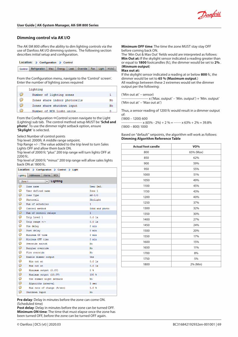
User Guide | AK-System Manager, AK-SM 800 Series
© Danfoss | DCS (vt) | 2020.03 BC316842192932en-001001 | 69
Dimming control via AK I/O
The AK-SM 800 offers the ability to dim lighting controls via the use of Danfoss AK I/O dimming systems. The following section describes initial setup and configuration.
From the Configuration menu, navigate to the ‘Control’ screen’. Enter the number of lighting zones required
From the ConfigurationControl screen navigate to the Light (Lighting) sub tab. The control method setup MUST be ‘Schd and photo’. To use the dimmer night setback option, ensure ‘Skylight’ is selected.
Select Number of control pointsTrip level: 2000fc A middle range setpoint.Trip Range +/- : The value added to the trip level to turn Sales Lights OFF and allow them back ON.Trip level of 2000 fc “plus” 200 trip range will turn lights OFF at 2200 fc.Trip level of 2000 fc “minus” 200 trip range will allow sales lights back ON at 1800 fc.
Pre delay: Delay in minutes before the zone can come ON. (Scheduled time)Post delay: Delay in minutes before the zone can be turned OFF.Minimum ON time: The time that must elapse once the zone has been turned OFF, before the zone can be turned OFF again.
Actual foot candle VO%
800 65% (Max)
850 62%
900 59%
950 55%
1000 51%
1050 49%
1100 45%
1150 43%
1200 40%
1250 37%
1300 32%
1350 30%
1400 27%
1450 24%
1500 20%
1550 17%
1600 15%
1650 11%
1700 8%
1750 5%
1800 2% (Min)
Minimum OFF time: The time the zone MUST stay stay OFF before coming back ON.The ‘Min Out & Max Out’ fields would are interpreted as follows:Min Out at: If the skylight sensor indicated a reading greater than or equal to 1800 footcandles (fc), the dimmer would be set to 2% . (Minmum output)Max out at:If the skylight sensor indicated a reading at or below 800 fc, the dimmer would be set to 65 % (Maximum output.)All readings between these 2 extremes would set the dimmer output per the following:
(‘Min out at’ – sensor)---------------------- x (‘Max. output’ – ‘Min. output’) + ‘Min. output’(‘Min out at’ – ‘Max out at’)
Thus, a sensor reading of 1200 fc would result in a dimmer output of:(1800 – 1200) 600----------------- x (65% - 2%) + 2 % = ------ x 63% + 2% = 39.8%(1800 – 800) 1000
Based on “default” setpoints, the algorithm will work as follows:Dimming Algorithm Reference Table

User Guide | AK-System Manager, AK-SM 800 Series
70 | BC316842192932en-001001 © Danfoss | DCS (vt) | 2020.03
Algorithm interval is the algorithm cycle.Max rate of change is the percentage of adjustment per second.With a setting of 1 % for a 1 second algorithm cycle, and a 2% minimum and 65 % maximum output, the full range can be covered in 63 seconds. (1 percent per second for 63 steps.)This schedule turns the zone ON and OFF on a time base. (Setup for 24 hours)
Once the main configuration screen is complete, navigate to the Variable Outputs tab, where a board and point address can be added for the 0-10 vdc board
Setup of analog inputs:Skylight sensor to PHOTO-SKY typeDimmer feedback to misc. conversion factor DIM FEEDBK
Once the lighting configuration is complete the details can be seen in the zone lighting detail screen. The detail screen will reflect status, Settings and Service tabs.

User Guide | AK-System Manager, AK-SM 800 Series
© Danfoss | DCS (vt) | 2020.03 BC316842192932en-001001 | 71
HVAC Configuration
Configuration Control HVAC
The AK-SM 820 and AK-SM 880 both offer HVAC control and support. Both the AK-SM 820 and 880 offer the same HVAC functionality, the only difference is the number of HVAC units that can be configured. HVAC control and support can be via centralized or de-centralized control. Centralized control offers the ability to control HVAC systems via Danfoss AK I/O modules. The de-centralized method allows support for specific field bus nodes.
The example below describes a typical centralized control method. As seen in the Refrigeration section, the built in HVAC control is based around a list of control questions. When answering these questions, the control inputs / outputs are being built and will be visible in the Address tab. Navigate to the ‘ConfigurationControlHVAC’ screen; here you will need to declare what type of HVAC control method is to be used.
For centralized control, select ‘AHU’ or ‘RTU’ from the drop down list. If you require de-centralized (field bus) control, select the controller type from the drop down list. Once selected use the setup tab to continue configuration. In the example below, AHU has been selected.
Initially, navigate to the ‘Configuration Control’ screen, and then declare how many HVAC units you require. In addition to the number of HVAC units, the following questions will also be populated;
# of phase loss monitors# of humidity sensors# of dewpoint sensors
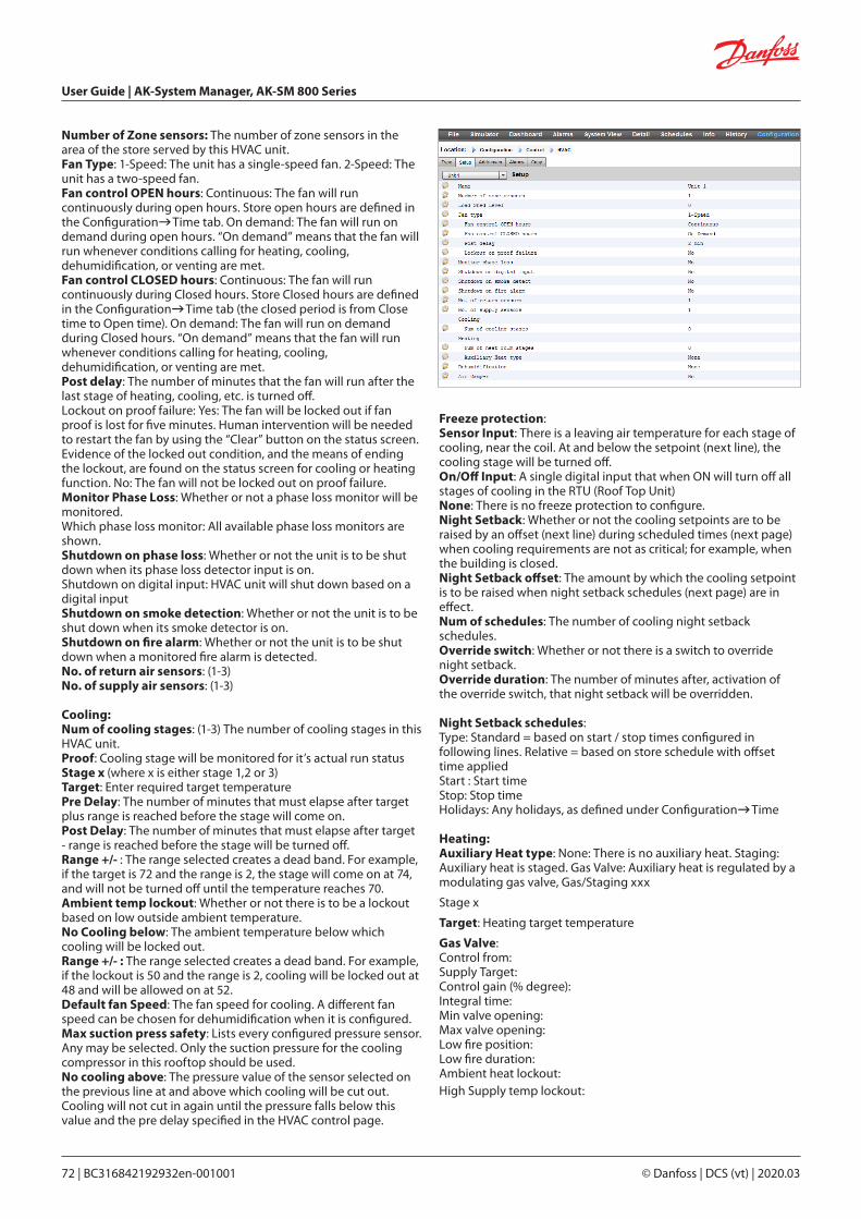
User Guide | AK-System Manager, AK-SM 800 Series
72 | BC316842192932en-001001 © Danfoss | DCS (vt) | 2020.03
Number of Zone sensors: The number of zone sensors in the area of the store served by this HVAC unit.Fan Type: 1-Speed: The unit has a single-speed fan. 2-Speed: The unit has a two-speed fan.Fan control OPEN hours: Continuous: The fan will run continuously during open hours. Store open hours are defined in the ConfigurationTime tab. On demand: The fan will run on demand during open hours. “On demand” means that the fan will run whenever conditions calling for heating, cooling, dehumidification, or venting are met.Fan control CLOSED hours: Continuous: The fan will run continuously during Closed hours. Store Closed hours are defined in the ConfigurationTime tab (the closed period is from Close time to Open time). On demand: The fan will run on demand during Closed hours. “On demand” means that the fan will run whenever conditions calling for heating, cooling, dehumidification, or venting are met.Post delay: The number of minutes that the fan will run after the last stage of heating, cooling, etc. is turned off.Lockout on proof failure: Yes: The fan will be locked out if fan proof is lost for five minutes. Human intervention will be needed to restart the fan by using the “Clear” button on the status screen. Evidence of the locked out condition, and the means of ending the lockout, are found on the status screen for cooling or heating function. No: The fan will not be locked out on proof failure.Monitor Phase Loss: Whether or not a phase loss monitor will be monitored.Which phase loss monitor: All available phase loss monitors are shown.Shutdown on phase loss: Whether or not the unit is to be shut down when its phase loss detector input is on.Shutdown on digital input: HVAC unit will shut down based on a digital inputShutdown on smoke detection: Whether or not the unit is to be shut down when its smoke detector is on.Shutdown on fire alarm: Whether or not the unit is to be shut down when a monitored fire alarm is detected.No. of return air sensors: (1-3)No. of supply air sensors: (1-3)
Cooling:Num of cooling stages: (1-3) The number of cooling stages in this HVAC unit.Proof: Cooling stage will be monitored for it’s actual run statusStage x (where x is either stage 1,2 or 3)Target: Enter required target temperaturePre Delay: The number of minutes that must elapse after target plus range is reached before the stage will come on.Post Delay: The number of minutes that must elapse after target - range is reached before the stage will be turned off.Range +/- : The range selected creates a dead band. For example, if the target is 72 and the range is 2, the stage will come on at 74, and will not be turned off until the temperature reaches 70.Ambient temp lockout: Whether or not there is to be a lockout based on low outside ambient temperature.No Cooling below: The ambient temperature below which cooling will be locked out.Range +/- : The range selected creates a dead band. For example, if the lockout is 50 and the range is 2, cooling will be locked out at 48 and will be allowed on at 52.Default fan Speed: The fan speed for cooling. A different fan speed can be chosen for dehumidification when it is configured.Max suction press safety: Lists every configured pressure sensor. Any may be selected. Only the suction pressure for the cooling compressor in this rooftop should be used.No cooling above: The pressure value of the sensor selected on the previous line at and above which cooling will be cut out. Cooling will not cut in again until the pressure falls below this value and the pre delay specified in the HVAC control page.
Freeze protection:Sensor Input: There is a leaving air temperature for each stage of cooling, near the coil. At and below the setpoint (next line), the cooling stage will be turned off.On/Off Input: A single digital input that when ON will turn off all stages of cooling in the RTU (Roof Top Unit)None: There is no freeze protection to configure.Night Setback: Whether or not the cooling setpoints are to be raised by an offset (next line) during scheduled times (next page) when cooling requirements are not as critical; for example, when the building is closed.Night Setback offset: The amount by which the cooling setpoint is to be raised when night setback schedules (next page) are in effect.Num of schedules: The number of cooling night setback schedules.Override switch: Whether or not there is a switch to override night setback.Override duration: The number of minutes after, activation of the override switch, that night setback will be overridden.
Night Setback schedules:Type: Standard = based on start / stop times configured in following lines. Relative = based on store schedule with offset time appliedStart : Start timeStop: Stop timeHolidays: Any holidays, as defined under ConfigurationTime
Heating:Auxiliary Heat type: None: There is no auxiliary heat. Staging: Auxiliary heat is staged. Gas Valve: Auxiliary heat is regulated by a modulating gas valve, Gas/Staging xxx
Stage x
Target: Heating target temperature
Gas Valve:Control from:Supply Target:Control gain (% degree):Integral time:Min valve opening:Max valve opening:Low fire position:Low fire duration:Ambient heat lockout:High Supply temp lockout:

User Guide | AK-System Manager, AK-SM 800 Series
© Danfoss | DCS (vt) | 2020.03 BC316842192932en-001001 | 73
Fan Speed:Night setback:Night setback offset:Num of schedules:Override switch:Night setback schedules:Dehumidification:‘None’ or ‘cooling’ (humidity, dewpoint or calculated dewpoint, and related setpoints and delays)Air Damper:If set to ‘yes’ it provides pre-delay, post-delay, ambient air temperature lockout and schedule options
AK-SC Built in HVAC control (Using AK Input / Output)Following from the Controllers tab, the Relay, Sensor, On/Off Inputs & Variable Outputs tabs allow the adding of the relevant I/O modules required for built in HVAC. Each line would have been ‘built’ depending on the answers given in the various HVAC setup screens (previously described).
If required, enter unique description.Enter correct address for the Board & Point input.Type can be changed according to the selections in the type drop down list.
HVAC Alarms - Alarms Tab
The alarms for the individual HVAC unit can be found under the Alarms tab.
Scroll down each appropriate line and press enter to change the alarm level, the available options being the same as found in previous alarm tab configurations. In addition to the alarm level, an alarm action number can be set (1-8), configure the alarm actions in the central alarm routing page (ConfigurationAlarms).
Note: For alarms to correctly activate, the central alarm routing page must also be configured. See Configuration Alarms
Define the Alarm Action for each alarm output - this links with the central AlarmsRouting page.
Define the Alarm level (Disabled, Log Only, Normal, Severe, Critical, Delete).

User Guide | AK-System Manager, AK-SM 800 Series
74 | BC316842192932en-001001 © Danfoss | DCS (vt) | 2020.03
The term Miscellaneous refers to the ability to monitor and control miscellaneous areas of an application using Danfoss AK I/O (modules). For example, a miscellaneous relay output may be required for an exhaust fan, a dispenser that adds chemicals, an oven, a produce fogger, or any other device that can’t or shouldn’t be treated like an ordinary refrigeration, HVAC, or lighting asset. Miscellaneous on/off, sensor inputs can be used in defining the control strategy for miscellaneous relay outputs. Any miscellaneous points configured can be monitored for history, and may be configured strictly for that purpose, or for alarms. Routable alarms can be created for any Miscellaneous point. For sensor inputs, the AK-SM allows custom conversion for non-Danfoss sensors that have a linear response (known as Conversion factors)
The initial Miscellaneous definition is set out in the ConfigurationControl page (see below). In addition to Relay, Sensor, On/Off Inputs and variable outputs the Misc section also has Conversion Factors & Calculations. Further details on conversion factors and calculations can be seen in this section.
Once the required misc points have been set (number required), configuration is done under the Misc tab.
Configuration Control MISC
Miscellaneous Configuration
Configuration-Control screen
In this example a miscellaneous sensor has been configured, but the same principle will apply if configuring Relays, On/Off and variable outputs. Under the Misc tab, navigate to the sensors tab. Enter a suitable description for the sensor, then under the Bd-Pt line, enter the board & point address for the sensor in question. In this example the address 01-1.2 has been assigned. Review the remaining items in the list and configure according to your site requirements.
Example of I/O module line up. The communication module (AK CM 101A) has an address set as 1, with module 1 having the sensor in location 2. This is then entered in the AK-SM as 01-1.2
CommunicationModule (address 1)
Module 1 Module 2 Up to 9 modules can be connected to ONE Communication Module
Rotary address switches
Sensor (01-1.2)
for this example the board and point address 01-1.2 is assigned

User Guide | AK-System Manager, AK-SM 800 Series
© Danfoss | DCS (vt) | 2020.03 BC316842192932en-001001 | 75
Relay Tab
Depending on control requirements the screen layout may differ.
Navigate though the options, adding custom name, AK I/O address, alarms, pre and post delays etc.
Note: Setting Broadcast to yes will make available the relay status on the AK-SM host network.
If a control input is needed to operate your misc relay, this can be selected on the Control Input line (you will need to configure your control input in advance)
Name: Enter custom description for relayBd-Pt: Enter a valid Board & Point address (using AK I/O modules)Broadcast: No: The value of the point will not be broadcast to be used in logic on other controllers.
Send: The value of the point (whether it is ON or OFF) will be available on the host network for use by other controllers. Be sure that each sending Board-Point combination is unique throughout the system. (If the controller at address #01 is sending from its Bd-Pt address 1-02, then no other controller can have an output at its Bd-Pt address 1-02 sending. Rec: The value of the point is being received from another controller on the host network. You must enter, in the Bd-Pt fields, the Bd-Pt address of the sending point.
Type: Normally Closed or Normally OpenControl Input: It is possible to use other defined points (including calculations) to act as the control Input - these will be seen in a drop down listMinimum Off: Define a min off time period to stop short cyclingPre Delay: Define a pre time delay before the relay activatesMinimum On: Define a min on time period to stop short cyclingPost Delay: Define a post time delay to minimize short cyclingNumber of alarms: Enter the amount of alarms (max 3)Alarm 1: Enter the alarm level (Disabled, Log only, Normal, Severe, Critical)
Type: Alarm if ON, Alarm if OFF, Cycles (enter number of cycles)
Delay: Enter delay time Units: Seconds, Minutes, Hours From: Defines alarm output time window To: Defines alarm output time window Days: Define the days associated with alarm Action: Define the alarm action
Example of Misc Relays Tab
If configured, navigate to additional relays via the drop down box
Relays Tab
The example below shows the Misc Relays tab. Navigate down the control lines and configure as required.
Any Misc points configured in the AK-SM system will be shown in the ‘System View’ under the Power/Misc window

User Guide | AK-System Manager, AK-SM 800 Series
76 | BC316842192932en-001001 © Danfoss | DCS (vt) | 2020.03
Sensors Tab
The example below shows the Misc Sensors tab. Navigate down the control lines and configure as required.
Sensors Tab
Depending on control requirements the screen layout may differ.
Navigate though the options, adding custom name, AK I/O address, alarms
Example of Misc Sensors Tab
Name: Enter custom description for sensorBd-Pt: Enter a valid Board & Point address (using AK I/O modules)
Broadcast: No: The value of the point will not be broadcast to be used in logic on other controllers.
Send: The value of the point (whether it is ON or OFF) will be available on the host network for use by other controllers. Be sure that each sending Board-Point combination is unique throughout the system. (If the controller at address #01 is sending from its Bd-Pt address 1-02, then no other controller can have an output at its Bd-Pt address 1-02 sending.
Rec: The value of the point is being received from another controller on the host network. You must enter, in the Bd-Pt fields, the Bd-Pt address of the sending point.
Type: Select from various option in the drop down list (this example uses a PT1000 sensor)
If configured, navigate to additional sensors via the drop down box
Configure alarm setpoint & actions
Control Input: It is possible to use other defined points (including calculations) to act as the control Input, these will be seen in a drop down list
Number of alarms: Enter the amount of alarms (max 3)
Alarm 1: Enter the alarm level (Disabled, Log only, Normal, Severe, Critical) Type: Alarm if above or if below limit (seen below) Limit: Enter the alarm limit Delay: Enter delay time Units: Seconds, Minutes, Hours From: Defines alarm output time window To: Defines alarm output time window Days: Define the days associated with alarm Action: Define the alarm actionSensor fail alarms: Enter the alarm level to issue alarm if sensor fails (Disabled, Log only, Normal, Severe, Critical)
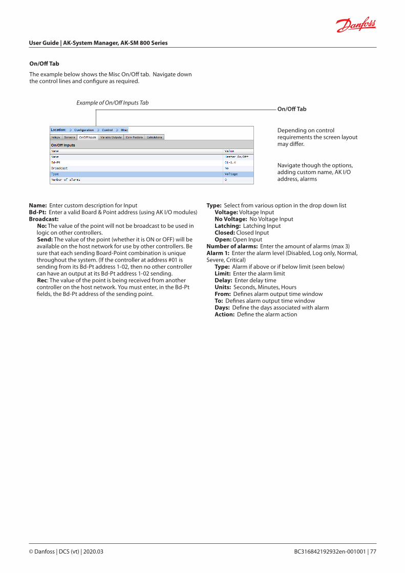
User Guide | AK-System Manager, AK-SM 800 Series
© Danfoss | DCS (vt) | 2020.03 BC316842192932en-001001 | 77
On/Off Tab
The example below shows the Misc On/Off tab. Navigate down the control lines and configure as required.
On/Off Tab
Depending on control requirements the screen layout may differ.
Navigate though the options, adding custom name, AK I/O address, alarms
Example of On/Off Inputs Tab
Name: Enter custom description for InputBd-Pt: Enter a valid Board & Point address (using AK I/O modules)Broadcast:
No: The value of the point will not be broadcast to be used in logic on other controllers. Send: The value of the point (whether it is ON or OFF) will be available on the host network for use by other controllers. Be sure that each sending Board-Point combination is unique throughout the system. (If the controller at address #01 is sending from its Bd-Pt address 1-02, then no other controller can have an output at its Bd-Pt address 1-02 sending. Rec: The value of the point is being received from another controller on the host network. You must enter, in the Bd-Pt fields, the Bd-Pt address of the sending point.
Type: Select from various option in the drop down list Voltage: Voltage Input No Voltage: No Voltage Input Latching: Latching Input Closed: Closed Input Open: Open InputNumber of alarms: Enter the amount of alarms (max 3)Alarm 1: Enter the alarm level (Disabled, Log only, Normal, Severe, Critical) Type: Alarm if above or if below limit (seen below) Limit: Enter the alarm limit Delay: Enter delay time Units: Seconds, Minutes, Hours From: Defines alarm output time window To: Defines alarm output time window Days: Define the days associated with alarm Action: Define the alarm action

User Guide | AK-System Manager, AK-SM 800 Series
78 | BC316842192932en-001001 © Danfoss | DCS (vt) | 2020.03
Variable Output TabDepending on control requirements the screen layout may differ.
Example of Variable Output Tab
If configured, navigate to additional Outputs via the drop down box
Variable outputs
Using a 0-10V water mixing valve application as an example, the following screen can be used on the AK-SM to provide control. The same principles can be applied against a wide range of control needs. Variable output control can also be seen in certain AK-SM Refrigeration, HVAC and Lighting control screens. Using the Miscellaneous area of the AK-SM a variable output point can be created. After authorization, navigate to the configurationcontrol page. Enter the required quantity of variable outputs, remembering to also add a sensor input (which will be later used as a water temperature reference).
Next, navigate to the Misc tab and scroll to the variable output tab. Enter a descriptive name and the board & point allocation (the point number will be 1 to 4). Define the working voltage range, here a 0-10 V range is set. The previously configured sensor input (water temp) can be defined, along with the output % range and is used as the control reference point.
Name: Enter custom description for OutputBd-Pt: Enter a valid Board & Point address. Variable output is done via VO2 board (described opposite)Range: Select from various option in the drop down list: 0-10, 10-0, 0-5 VoltsControl SensorOutput 0%Output 100%Override type (Relay Output, On/Off)Override pointFailsafe Type (Stay unchanged, Maximum output, Minimum output, predefined value - user definable) Number of alarms: Enter the amount of alarms (max 3)Alarm 1: Enter the alarm level (Disabled, Log only, Normal, Severe, Critical) Type: Alarm if above or if below limit (seen below) Limit: Enter the alarm limit Delay: Enter delay time Units: Seconds, Minutes, Hours From: Defines alarm output time window To: Defines alarm output time window Days: Define the days associated with alarm Action: Define the alarm action
Controlling sensorIn this example the sensor was pre-configured and labelled as ‘water temp’
Failsafe value (see below for description)
An override relay or switch can be added if required (not used in this example). Finally an analog output fail safe can be configured. The fail safe feature is to ensure safe operation during power outages, network disturbances etc.
The following options are available;• Stay unchanged - upon failure keep output voltage unchanged• Maximum output - set output to 100%• Minimum output - set output to 0%• Predefined value - user set value %

User Guide | AK-System Manager, AK-SM 800 Series
© Danfoss | DCS (vt) | 2020.03 BC316842192932en-001001 | 79
AK-XM 103A Variable Output board
Your AK-SM fully supports the family of Danfoss I/O modules. The I/O family consists of various analog inputs, digital outputs, and relays. New to the I/O family is the AK-XM 103A (080Z0032) analog input /output module. This new module offers x4 analog inputs and x4 analog outputs, allowing easy control of a variety of control applications.
Terminal 9: 12 V max 100 mATerminal 10: 5 V max 25 mA
Terminal 11, 12:
Terminal 2, 4, 6, 8: GND-AI 1-4Terminal 17, 19: GND-AO 1+2Terminal 21, 23: GND-AO 3+4
Galvanic isolation:AI 1-4 ≠ AO 1-2 ≠ AO 3-4

User Guide | AK-System Manager, AK-SM 800 Series
80 | BC316842192932en-001001 © Danfoss | DCS (vt) | 2020.03
Example of Conversion Factors Tab
Conversion Factors
Conversion factors are used for sensors that have an output range or range-to-value relationship not already defined as one of the named “types” in the sensor input configuration list box. The following example highlights the Conversion Factor screen.
No of conversion factors: Enter the required amount of conversion factorsConv 1: Name for conversion factor (user changeable)Units: Select from a range of unit types: psi Bar °F % °C ppm (Parts Per million) V (Volts) Amp Kw kWh Hz gpm (gallons per min) fps pH fc lpm (litres per minute) lps (litres per second) Minimum Input: Maximum Input: Minimum output: Maximum output: Lux:
Conversion Factor TabDepending on control requirements the screen layout may differ.

User Guide | AK-System Manager, AK-SM 800 Series
© Danfoss | DCS (vt) | 2020.03 BC316842192932en-001001 | 81
Detail View
Settings (see also configuration)
Status
Settings (see also configuration)
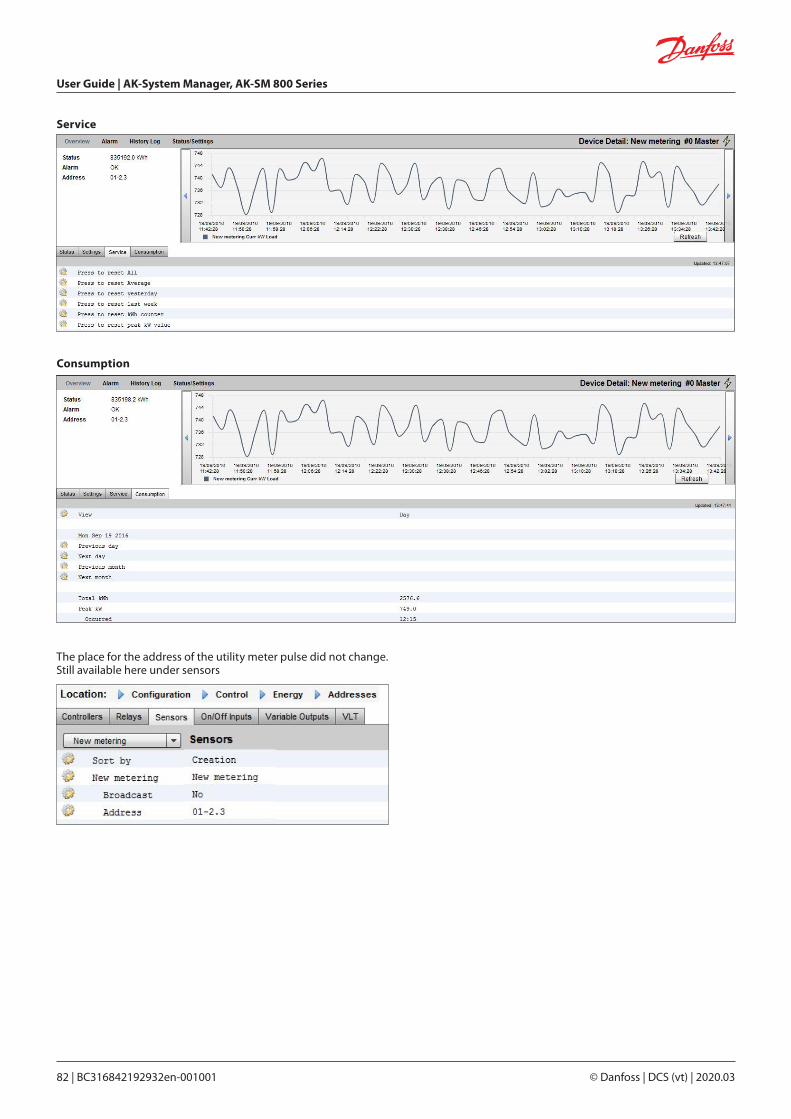
User Guide | AK-System Manager, AK-SM 800 Series
82 | BC316842192932en-001001 © Danfoss | DCS (vt) | 2020.03
Service
Consumption
The place for the address of the utility meter pulse did not change. Still available here under sensors
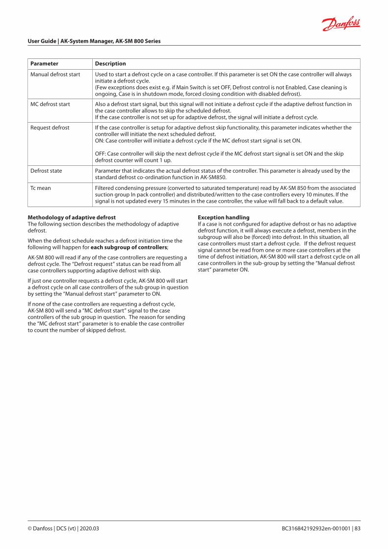
User Guide | AK-System Manager, AK-SM 800 Series
© Danfoss | DCS (vt) | 2020.03 BC316842192932en-001001 | 83
Parameter Description
Manual defrost start Used to start a defrost cycle on a case controller. If this parameter is set ON the case controller will always initiate a defrost cycle.(Few exceptions does exist e.g. if Main Switch is set OFF, Defrost control is not Enabled, Case cleaning is ongoing, Case is in shutdown mode, forced closing condition with disabled defrost).
MC defrost start Also a defrost start signal, but this signal will not initiate a defrost cycle if the adaptive defrost function in the case controller allows to skip the scheduled defrost. If the case controller is not set up for adaptive defrost, the signal will initiate a defrost cycle.
Request defrost If the case controller is setup for adaptive defrost skip functionality, this parameter indicates whether the controller will initiate the next scheduled defrost.ON: Case controller will initiate a defrost cycle if the MC defrost start signal is set ON.
OFF: Case controller will skip the next defrost cycle if the MC defrost start signal is set ON and the skip defrost counter will count 1 up.
Defrost state Parameter that indicates the actual defrost status of the controller. This parameter is already used by the standard defrost co-ordination function in AK-SM850.
Tc mean Filtered condensing pressure (converted to saturated temperature) read by AK-SM 850 from the associated suction group In pack controller) and distributed/written to the case controllers every 10 minutes. If the signal is not updated every 15 minutes in the case controller, the value will fall back to a default value.
Methodology of adaptive defrost The following section describes the methodology of adaptive defrost.
When the defrost schedule reaches a defrost initiation time the following will happen for each subgroup of controllers;
AK-SM 800 will read if any of the case controllers are requesting a defrost cycle. The “Defrost request” status can be read from all case controllers supporting adaptive defrost with skip.
If just one controller requests a defrost cycle, AK-SM 800 will start a defrost cycle on all case controllers of the sub group in question by setting the “Manual defrost start” parameter to ON.
If none of the case controllers are requesting a defrost cycle, AK-SM 800 will send a “MC defrost start” signal to the case controllers of the sub group in question. The reason for sending the “MC defrost start” parameter is to enable the case controller to count the number of skipped defrost.
Exception handlingIf a case is not configured for adaptive defrost or has no adaptive defrost function, it will always execute a defrost, members in the subgroup will also be (forced) into defrost. In this situation, all case controllers must start a defrost cycle. If the defrost request signal cannot be read from one or more case controllers at the time of defrost initiation, AK-SM 800 will start a defrost cycle on all case controllers in the sub-group by setting the “Manual defrost start” parameter ON.

User Guide | AK-System Manager, AK-SM 800 Series
84 | BC316842192932en-001001 © Danfoss | DCS (vt) | 2020.03
Coordinated Adaptive Defrost schedule and sub-grouping of controllers
Setting up an (coordinated) adaptive defrost schedule Prior to any defrost schedule configuration, it is required that the relevant case controls are configured to accept adaptive defrost (i.e. set controller d21 AD Mode =4).
Under the Configuration>Control>Refrigeration>Schedules tab, create a new schedule – type Adaptive Defrost.
Process diagramThe diagram below shows the process for defrost initiation for each sub group of controllers.
Selection of adaptive defrost schedule
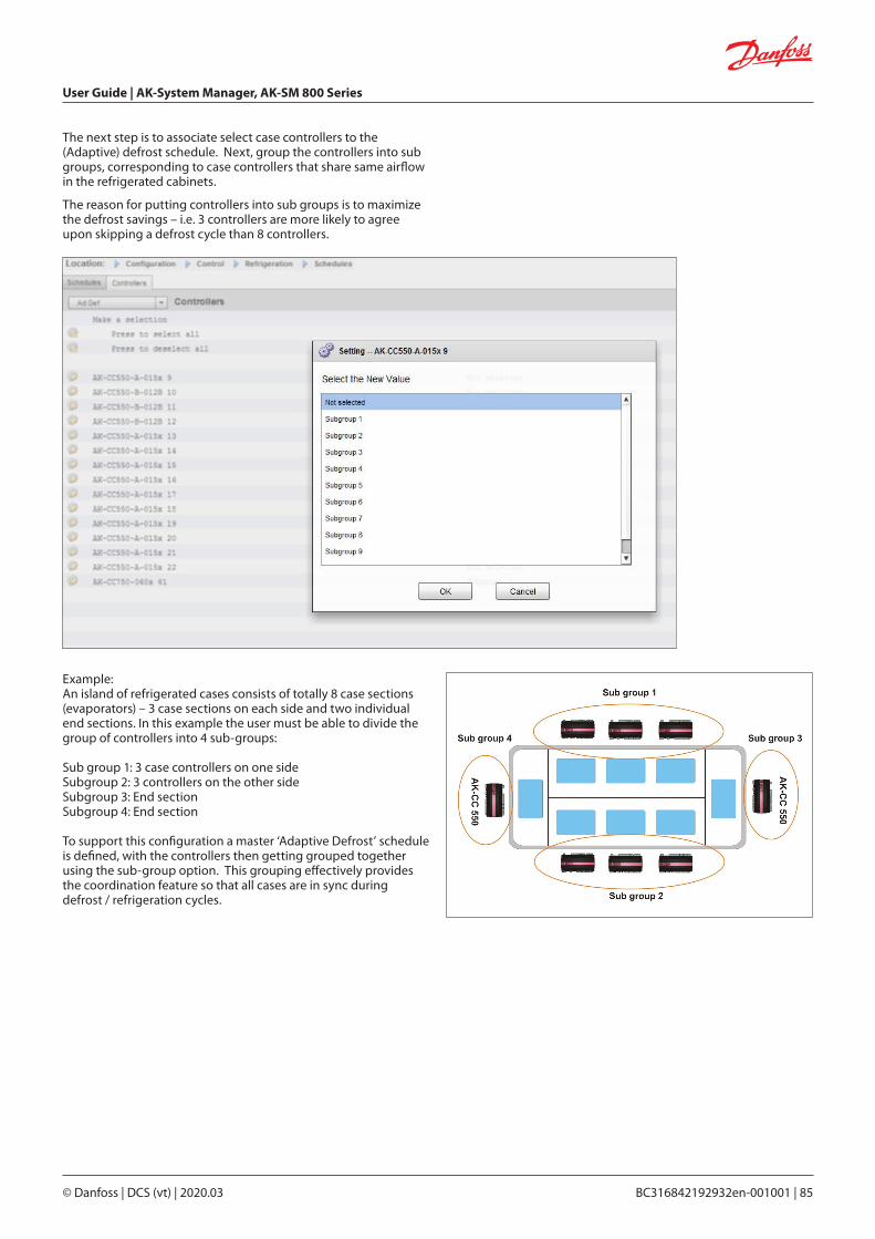
User Guide | AK-System Manager, AK-SM 800 Series
© Danfoss | DCS (vt) | 2020.03 BC316842192932en-001001 | 85
The next step is to associate select case controllers to the (Adaptive) defrost schedule. Next, group the controllers into sub groups, corresponding to case controllers that share same airflow in the refrigerated cabinets.
The reason for putting controllers into sub groups is to maximize the defrost savings – i.e. 3 controllers are more likely to agree upon skipping a defrost cycle than 8 controllers.
Example:An island of refrigerated cases consists of totally 8 case sections (evaporators) – 3 case sections on each side and two individual end sections. In this example the user must be able to divide the group of controllers into 4 sub-groups:
Sub group 1: 3 case controllers on one sideSubgroup 2: 3 controllers on the other sideSubgroup 3: End sectionSubgroup 4: End section
To support this configuration a master ‘Adaptive Defrost’ schedule is defined, with the controllers then getting grouped together using the sub-group option. This grouping effectively provides the coordination feature so that all cases are in sync during defrost / refrigeration cycles.

User Guide | AK-System Manager, AK-SM 800 Series
86 | BC316842192932en-001001 © Danfoss | DCS (vt) | 2020.03
Manual defrost
The user can manually start a defrost at an individual case level (via device detail screen>Manual tab) or a schedule wide command can be performed. To initiate a schedule wide (all controls associated with that particular master defrost schedule) navigate to the schedule screen (Configuration>Control>Refrigeration>Schedules) and double click or press the ‘turn on now’ action line. The status ‘defrost group’ will then be shown under this schedule screen.

User Guide | AK-System Manager, AK-SM 800 Series
© Danfoss | DCS (vt) | 2020.03 BC316842192932en-001001 | 87
Configuration Control ENERGY
The AK-SM system can monitor Danfoss-approved energy meters which have a network interface. In addition to the network meter models, pulse inputs can be fed from a wide range of non supported meters to AK I/O pulse boards & thus basic kWh monitoring can be done. Once either a supported meter or pulse input has been configured, the AK-SM can display current electrical status and log data for history purposes. In addition to viewing and recording electrical data, demand limiting can be performed on lighting and HVAC loads.
The AK-SM system can have a max of 80 meters, only one of the meters connected to an AK-SM can be used for demand limiting.The following section describes the configuration of Pulse and network meter types, and highlights the demand limiting function.
The Danfoss approved power meters can be seen when selecting meter type under the control question in ConfigurationControl page and are described in the example below.
Detailed configuration is done under the Energy tab (ConfigurationControlEnergy)
The initial meter configuration is done under the ConfigurationControl page. Define how many Meters are required, then select meter type..
Energy meter choices:Pulse/Vol = used to record volume via pulse (set to Liter, Gallon, Cubic meter (m3), Cubik feet (ft3)Pulse = Output from meter fed in to AK I/O moduleWN Plus= WattNode + brand meter (supplied by Danfoss). CG_EM24AV0, AV5,AV6,AV9 = Carlo Gavazzi EM24 (Note NOT compatible with other MODBUS nodes on network)VER_EH8035/36 = Veris modbus meterCarlo Gavazzi WM30AV5 is compatible with other MODBUS devices on the same MODBUS network
Configuration Control ENERGY [Pulse input from meter]
From the ConfigurationControl page, navigate to the Energy tab. This example will describe the configuration of a Pulse meter type. Choose this ‘type’ if a non supported power meter has a pulse output that can be connected to a pulse AK I/O module (AK-XM 107A).
Under the Meter Setup tab the following screen can be seen;
Meter Setup Tab. All meter types can be seen in this window. In this example, pulse meter has been selected.
Enter custom name for meterIf using the pulse meter input for demand limiting, answer ‘yes’ to the question ‘use for demand limiting’See descriptions below for further details.
Energy Configuration
Energy
User Guide | AK-System Manager, AK-SM 800 Series
88 | BC316842192932en-001001 © Danfoss | DCS (vt) | 2020.03
Name: Enter custom description for meterWindow Size: [Visible only when demand limiting set to yes] The window width is set to 15, 20, or 30 minutes. Every minute, the window “slides” forward so that it always contains the most recent period of time. Each minute the accumulated KW during that minute is recorded.Watt-hours per pulse: Enter relevant value- Watt-hour per pulse Collect History: Select yes to collect history from this meter Use for demand limiting: Whether or not this meter is to be used for demand limiting.Normal Load 01 - 24 Hrs: Enter the upper demand limit you do not wish to exceed for the given hour of the day (defined by each hour line) under normal operating conditions (when using normal power). There is one field for each hour of the day, from 01 to 24.Maximum Emergency Load: Enter the upper demand limit that you do not wish to exceed when the emergency generator is running.Start Shedding at: Enter the percent of maximum load at which you want to start shedding loads.Start restoring at: Enter the percent of maximum load at which you want to start restoring loads which have been shed.Enable coupling switch: In installations where there are two transformers and/or two emergency generators, a coupling switch can be used to connect both loads to one source in case the other source fails.Number of normal steps: The number of steps (levels) which you will allow to be shed under normal conditions.Number of emergency steps: The number of steps (levels) which you will allow to be shed when the emergency generator is running.Normal:
Soft start begin level: 0 to the number of normal steps set above, up to 10; if 8 normal steps are configured, for example, the upper limit of this entry is 8) This entry specifies the level down to which loads will be turned on when the emergency generator starts. A level will be added each minute unless the specified emergency load for shedding to start is reached. Couple begin level: [Visible when coupling switch = yes] Emergency generator control - Enter the upper demand limit you do not wish to exceed for the given hour of the day under normal operating conditions (when using normal power). There is one field for each hour of the day, from 00 to 23. This screen has two pages in order to list all the hours of the day.
Emergency: Soft start begin level: [Emergency generator control] 0 to the number of emergency steps set above, up to 10; (if 8 emergency steps are configured, for example, the upper limit of this entry is 8) This entry specifies the level down to which loads will be turned on when the emergency generator starts. A level will be added each minute unless the specified emergency load for shedding to start is reached. Coupling begin level: [Emergency generator control] Enter the upper demand limit you do not wish to exceed for the given hour of the day under normal operating conditions (when using normal power). There is one field for each hour of the day, from 00 to 23. This screen has two pages in order to list all the hours of the day.
Note about soft starts
The effect of a soft start is to slowly add load to the generator after it starts. If, for instance, soft start begin level is set to 6, when the generator starts only refrigeration loads and loads assigned level 7 through 11 will be on. After one minute, if the load is below the “start shedding at” percentage of maximum emergency load, level 6 will be turned on. After another minute, the same decision will be made for level 5, and so on down to level one. If at any time the load reaches the “start shedding at” percentage, load shedding will begin again until the system reaches the “start restoring at” percentage.
DEMAND LIMITING TAB (see dedicated section on Demand Limiting)
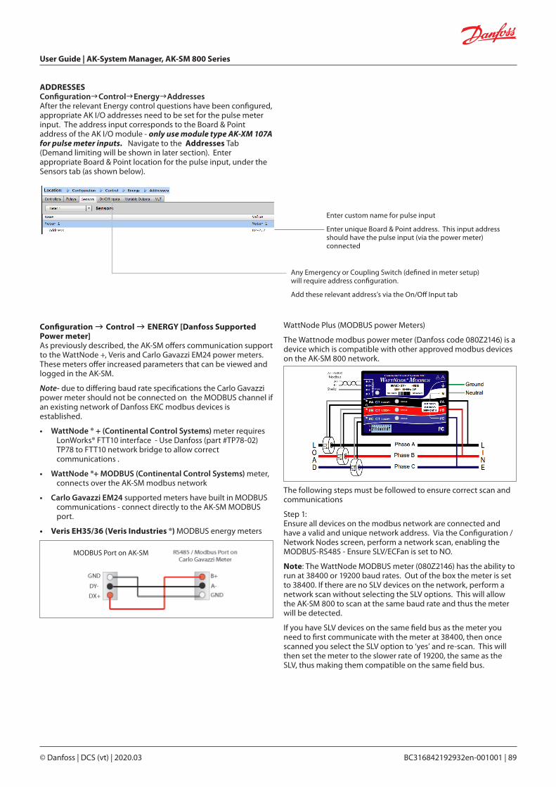
User Guide | AK-System Manager, AK-SM 800 Series
© Danfoss | DCS (vt) | 2020.03 BC316842192932en-001001 | 89
Configuration Control ENERGY [Danfoss Supported Power meter]As previously described, the AK-SM offers communication support to the WattNode +, Veris and Carlo Gavazzi EM24 power meters. These meters offer increased parameters that can be viewed and logged in the AK-SM.
Note- due to differing baud rate specifications the Carlo Gavazzi power meter should not be connected on the MODBUS channel if an existing network of Danfoss EKC modbus devices is established.
• WattNode ® + (Continental Control Systems) meter requires LonWorks® FTT10 interface - Use Danfoss (part #TP78-02) TP78 to FTT10 network bridge to allow correct communications .
• WattNode ®+ MODBUS (Continental Control Systems) meter, connects over the AK-SM modbus network
• Carlo Gavazzi EM24 supported meters have built in MODBUS communications - connect directly to the AK-SM MODBUS port.
• Veris EH35/36 (Veris Industries ®) MODBUS energy meters
Enter custom name for pulse input
Enter unique Board & Point address. This input address should have the pulse input (via the power meter) connected
Any Emergency or Coupling Switch (defined in meter setup) will require address configuration.
Add these relevant address’s via the On/Off Input tab
ADDRESSESConfigurationControlEnergyAddressesAfter the relevant Energy control questions have been configured, appropriate AK I/O addresses need to be set for the pulse meter input. The address input corresponds to the Board & Point address of the AK I/O module - only use module type AK-XM 107A for pulse meter inputs. Navigate to the Addresses Tab (Demand limiting will be shown in later section). Enter appropriate Board & Point location for the pulse input, under the Sensors tab (as shown below).
WattNode Plus (MODBUS power Meters)
The Wattnode modbus power meter (Danfoss code 080Z2146) is a device which is compatible with other approved modbus devices on the AK-SM 800 network.
The following steps must be followed to ensure correct scan and communications
Step 1: Ensure all devices on the modbus network are connected and have a valid and unique network address. Via the Configuration / Network Nodes screen, perform a network scan, enabling the MODBUS-RS485 - Ensure SLV/ECFan is set to NO.
Note: The WattNode MODBUS meter (080Z2146) has the ability to run at 38400 or 19200 baud rates. Out of the box the meter is set to 38400. If there are no SLV devices on the network, perform a network scan without selecting the SLV options. This will allow the AK-SM 800 to scan at the same baud rate and thus the meter will be detected.
If you have SLV devices on the same field bus as the meter you need to first communicate with the meter at 38400, then once scanned you select the SLV option to ‘yes’ and re-scan. This will then set the meter to the slower rate of 19200, the same as the SLV, thus making them compatible on the same field bus.
MODBUS Port on AK-SM

User Guide | AK-System Manager, AK-SM 800 Series
90 | BC316842192932en-001001 © Danfoss | DCS (vt) | 2020.03
Configuration Control ENERGY [Danfoss Supported Power meter]This example highlights a Danfoss supported meter WattNode + MODBUS. Having already defined the power meter as ‘WN Plus/MB’ under the control page, navigate to the ConfigurationControlEnergy page. Under type, select WattNode MB (MODBUS). The physical connection to the MODBUS network should keep the polarity (+ terminal should be to the + terminal on the Wattnode)
Using the drop down list, the WattNode + meter has been selected.Name: Enter custom description for meter
Amperage: Select the amperage of the CT’s connected to the Wattnode +. Collect History: Select yes to collect history from this meter Power Update: Interval to which power is measured.Energy Update: The interval over which energy (the integral of power over time) is calculated. Reactive Update: The interval over which reactive components are recalculated. Demand Period: The interval over which demand is calculated. Demand is defined as average power over a specified time interval. Demand Subintervals: The # of divisions of the demand period used when calculating a “rolling demand” using a “sliding window.”
After the relevant Energy control questions have been configured, the meter must have the address correctly configured. To add the WattNode + modbus meter to the AK-SM network, ensure all network wiring is in place and that power has been applied to the WattNode + meter. Navigate to the addresses tab and then enter the same address that is already set in the meter. Perform a network scan to bring the WattNode + meter on line.
Select the address tab to enter the address which has been assigned in the Wattnode meter (bit switches)
Remember to correctly wire and use the appropriate modbus port on the AK-SM.
Carlo Gavazzi ® power meter configuration (used in junction with RS485 AK-SM Model)
The following section describes the required steps to connect & configure the Carlo Gavazzi EM24xx meter over a modbus network connection.
Before any configuration can take place, ensure the meter is securely wired, has a valid network address (different from any other nodes on the ‘Controller’ network) and has a baud rate set to 9600- consult the meter manual for specific information on how to set the network address & baud rate. The data format is 1 start bit, 8 data bit, no parity and 1 stop bit.
Once set, ensure correct interconnection to the RS485 modbus port on the AK-SM.
(1) To avoid errors due to the signal reflections or line coupling, it is necessary to terminate the bus at the beginning and at the end (inserting a 120 ohm 1/2W 5% resistor between line B and A in the last instrument and in the Host interface).
(2) The network termination is necessary even in case of point-to-point connection and/or of short distances.
(3) For connections longer than 1200m a signal repeater is necessary.
Once all communication wiring has been set, perform a network scan- details of how to perform network scans can be seen in the Network Nodes Section of this user guide. Ensure MODBUS channel is checked in the Node Overview page.
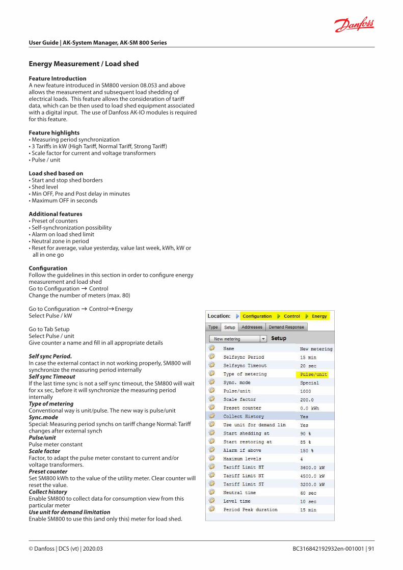
User Guide | AK-System Manager, AK-SM 800 Series
© Danfoss | DCS (vt) | 2020.03 BC316842192932en-001001 | 91
Energy Measurement / Load shed
Feature IntroductionA new feature introduced in SM800 version 08.053 and above allows the measurement and subsequent load shedding of electrical loads. This feature allows the consideration of tariff data, which can be then used to load shed equipment associated with a digital input. The use of Danfoss AK-IO modules is required for this feature.
Feature highlights• Measuring period synchronization• 3 Tariffs in kW (High Tariff, Normal Tariff, Strong Tariff)• Scale factor for current and voltage transformers• Pulse / unit
Load shed based on• Start and stop shed borders• Shed level• Min OFF, Pre and Post delay in minutes• Maximum OFF in seconds
Additional features• Preset of counters• Self-synchronization possibility• Alarm on load shed limit• Neutral zone in period• Reset for average, value yesterday, value last week, kWh, kW or
all in one go
ConfigurationFollow the guidelines in this section in order to configure energy measurement and load shedGo to Configuration ControlChange the number of meters (max. 80)
Go to Configuration ControlEnergySelect Pulse / kW
Go to Tab SetupSelect Pulse / unitGive counter a name and fill in all appropriate details
Self sync Period.In case the external contact in not working properly, SM800 will synchronize the measuring period internallySelf sync TimeoutIf the last time sync is not a self sync timeout, the SM800 will wait for xx sec, before it will synchronize the measuring period internallyType of meteringConventional way is unit/pulse. The new way is pulse/unitSync.modeSpecial: Measuring period synchs on tariff change Normal: Tariff changes after external synchPulse/unitPulse meter constantScale factorFactor, to adapt the pulse meter constant to current and/or voltage transformers.Preset counterSet SM800 kWh to the value of the utility meter. Clear counter will reset the value.Collect historyEnable SM800 to collect data for consumption view from this particular meterUse unit for demand limitationEnable SM800 to use this (and only this) meter for load shed.

User Guide | AK-System Manager, AK-SM 800 Series
92 | BC316842192932en-001001 © Danfoss | DCS (vt) | 2020.03
Start shedding atSM800 is constantly calculating the energy which is allowed until the rest of the period without the risk to pass the max. limit. In this example the load shed starts if 90% of the max value is reachedStart restoring atSM800 is constantly calculating the energy which is allowed until the rest of the period without the risk to pass the max. limit. If the energy consumption is decreasing and the system is satisfied with the calculation the restoring of the levels starts. In this example the restoring starts if the consumption falls below 85% of the max value.Alarm if aboveIf the system is passing above the limit an alarm will be created. In this example the alarm will be send out if the limit is 50% above the max value.Maximum levelThe system can handle max 4 levels (priorities) for load shedTariff limit HT/NT/STMaximum value in kW Neutral timeTime in sec. for the beginning of a period where load shed is inactiveLevel timeTime how long the calculation stays in a level before it goes to next levelPeriod Peak durationBasis time for calculation on the peak
Addressing:Go to Tab Addresses and On/Off Inputs to find the addresses for synch and tariffs.NT does not need an address because it is NT, if it is not HT.If ST is active it doesn’t matter which status NT or HT has.

User Guide | AK-System Manager, AK-SM 800 Series
© Danfoss | DCS (vt) | 2020.03 BC316842192932en-001001 | 93
Under detail energy the Sm8xx supports following information to the user:1. Status a. total consumption since start b. Current power in kW c. Peak power in kW
Detail Energy
2. Settings (example shows pulse meter)a. Nameb. Window size for demand limitc. Pulse rate in Wh/pulsed. Collect history (yes or no)e. Use this meter for demand limitation
3.Servicea. Reset kWhb. Reset peak
4. Consumption (to present consumption and peak from history)a. View total, monthly, weekly or daily valuesb. Select time frame
i. Total from/toii. previous month and next monthiii. previous week and next weekiv. previous day and next day
In case of total view it is possible to delete history for this particular meter

User Guide | AK-System Manager, AK-SM 800 Series
94 | BC316842192932en-001001 © Danfoss | DCS (vt) | 2020.03
Your AK-SM has built in functionality to facilitate enterprise demand limiting, via the Danfoss Electronic Delivered Services (EDS) offering.Contact your local Danofss sales rep for more details
The term Load Shed in the AK-SM is used to describe a function that allows an enterprise connection to schedule and actively turn off / on configured electrical loads for a period of time.
Once locally configured, your AK-SM can be fully managed via the Danfoss EDS (Electronic Delivered Services). Once logged on, the demand response enterprise dashboard allows retailers to participate in demand response incentive programs via a single, web-based portal. All site configuration, job scheduling, execution, status monitoring, and meter data extraction is completed from one web application.
Why Demand Response?Participate in demand response programs.Quickly curtail energy usage across your enterprise. Single web portal for all configuration, execution, and utility reporting. For further details, contact your local Danfoss representative.
Minimum requirements:AK-SM version V08_001 or higher of firmware.A connection between customer stores and Danfoss EDS –via VPN connection.
Enterprise Load Shed (via Danfoss EDS Service)
Enter load shed index (0-4)
The power rating slot can be used as a note to what the load is. This has no functional purpose except for notification purposes
Enter a required post delay. This ensures once the load shed event has finished not all system loads will start up at the same time, which could result in electrical overload conditions
Results
Now the AK-SM has been set for load shed, with the appropriate levels set, the enterprise user can now schedule load shed jobs. Once logged in to the Danfoss enterprise dashboard the user can select multiple sites and select a time and duration, with a load shed level action.
In our example above, if the enterprise user wishes to reduce maximum load for a period of time, a job would be created in the enterprise dashboard and the index ‘4’ would be issued to all selected AK-SM units across the customers estate. The effect is that ALL applications that have an index of 4 and below will turn off for that period of time (and re-start after any post delays). The result in our example here is that all HVAC and lighting will switch off. Another example would be using the load shed index of 3. This would then only shut down ALL applications set at 3 and below. In this example that would be the Lighting, the HVAC would continue to operate.
ConfigurationThis section will focus on the local (AK-SM) configuration, and assumes some HVAC and Lighting have been previously configured.The available load Shed Points (HVAC, Lighting Zones, Misc) are configured within the AK-SM. From the Configuration/Control/Energy/Demand Response screen select the Load Shed tab. Any previously configured HVAC, Lighting or Misc Relay will be visible.
The example below shows the HVAC and Lighting sections. The two HVAC units are shown and a load shed index of ‘4’ has been entered. The available index range is from 0-4 and once set in the AK-SM is used in the enterprise service to dictate what level of load shed the scheduled job (via the enterprise) will execute.The Lighting tab has been set to load shed level index 3.

User Guide | AK-System Manager, AK-SM 800 Series
© Danfoss | DCS (vt) | 2020.03 BC316842192932en-001001 | 95
The AK-SM Demand Limiting function is based on a designated utility power meter. Only one meter can be assigned Demand limiting, even though up to 80 meters can be connected to the AK-SM. Once a meter has been selected, the Demand Limit function can be applied against any Lighting and HVAC load.
Utility demand is monitored every minute. Every minute, the most recent n minutes are averaged (where n is the width of the configured window, 15, 20, or 30 minutes defined in the meter set up window ConfigurationControlEnergy). If the average reaches the configured “start shedding at” percentage of configured maximum demand, Step one (all lighting zones and HVAC units assigned to level 1) will be turned off. After one minute, when the average is calculated again, if the demand is still above the configured percentage of configured maximum demand, level two will be shed, and so on. When demand has dropped to the “start restoring at” level, the last level shed will be restored, and then the others in descending order, so that the last load restored will be the one which was shed first. Restoration will continue as long as the load remains below the “start shedding at” percentage.
If both normal and emergency load limits are to be established, the relative on/off input for the automatic transfer switch must be wired and configured. In addition, if the site has a coupling switch, you must wire and configure an on/off input for the coupling switch. Priority Levels (normal conditions)Levels are shed in ascending order: level 1, then level 2, and so on up to the highest level configured, limited by the number of stepsallowed. Levels above the number of steps configured will not be shed unless the meter configuration is changed (ConfigurationControlEnergy meter setup). Since there are only up to ten steps, loads assigned level 11 will never be shed. It is recommended that loads which are not to be shed are left at level 11, the default value.
Demand Limiting
Enter the required Shed levels & Emergency levels for the HVAC & Lighting systems.
Emergency level The priority for shedding when the emergency generator is running. If a load is assigned level 0 (zero) for either normal or emergency conditions, the load will never come on under those conditions.
ConfigurationControlEnergy Demand LimitingAs previously mentioned the Demand Limiting function is applied against HVAC and Lighting loads. This example assumes that both HVAC and lighting have been defined in the AK-SM and that a meter has been selected for Demand Limiting.Navigate to the Demand Limiting tab. The HVAC and lighting systems will be seen in this page, allowing the configuration of shed levels.

User Guide | AK-System Manager, AK-SM 800 Series
96 | BC316842192932en-001001 © Danfoss | DCS (vt) | 2020.03
Double click to add new calculation
Example of Calculations Tab
CalculationsMiscellaneous calculations are used to create custom logic. The AK-SM has the capacity for a total of 96 calculations which can be used to ‘drive’ miscellaneous logic where special applications are required. There are several ways to formulate calculations for a given requirement, but testing as you go is a ‘must’ in order to confirm desired results. A calculated point created here can be used anywhere a board & point address can be referenced. The calculated points processor is a true boolean processor, with a full complement of argument types and operators. Every configured calculated point will be listed. The fields are as follows:
Boolean Logic / Calculations
After adding a new calculation, a default screen will be shown (similar to the example below). The screen is divided into three areas, which from top to bottom are the following:
Heading area The heading of the screen tells what type and style of calculation point will be created.
Data definitions area This area contains information that identifies points that will be used in the logical statements in the next area, and the current value of each. The area by default has lines for two definitions, but it can be enlarged by double clicking the ***Press to insert new line ****. You will see this done in a few pages during the presentation of our first example.
New Calc When first entering the calculations screen a line called New Calc is shown. To configure a new point, double click this field.DescriptionThe type of point (OI or SI). If an SI, the description will usually include the units.Point(Ca-01 to Ca-96) The name of the calculated point.Value The current value or state of the point. This will be on or off for OI points, and a value for SI points.Status (Online, Offline, Error)
Rules area This is the area that will contain the logical statements that determine whether the point is on or off (OI) or the value (SI) that is used. At the bottom of the area is the current value of the result.
Heading
Data Definitions
Rules Area
‘Else’ line

User Guide | AK-System Manager, AK-SM 800 Series
© Danfoss | DCS (vt) | 2020.03 BC316842192932en-001001 | 97
Simple Calculation example:
Calculate the average of 3 different temperature sensors. Show this resulting average value in a miscellaneous sensor driven by the calculation 1. Creating the miscellaneous points for this calculation- Sensor inputs:Create 3 sensor inputs (the 3rd is used to display the average through the calculation).
2.
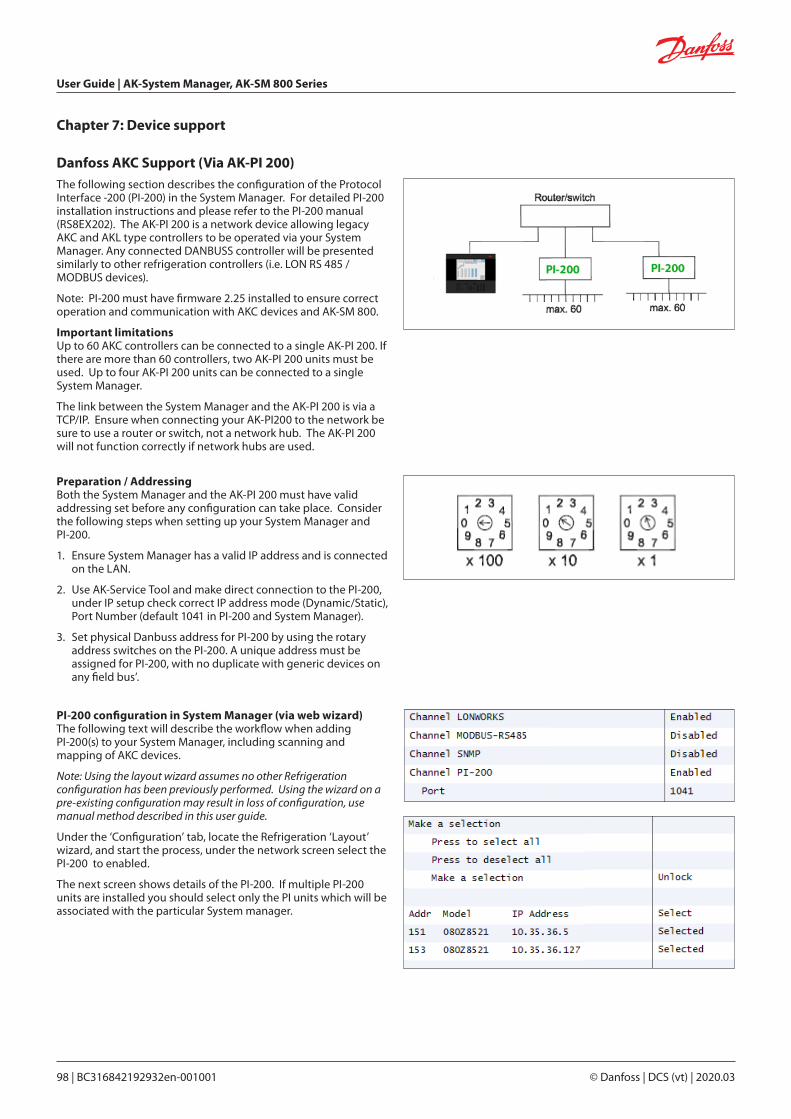
User Guide | AK-System Manager, AK-SM 800 Series
98 | BC316842192932en-001001 © Danfoss | DCS (vt) | 2020.03
Danfoss AKC Support (Via AK-PI 200)The following section describes the configuration of the Protocol Interface -200 (PI-200) in the System Manager. For detailed PI-200 installation instructions and please refer to the PI-200 manual (RS8EX202). The AK-PI 200 is a network device allowing legacy AKC and AKL type controllers to be operated via your System Manager. Any connected DANBUSS controller will be presented similarly to other refrigeration controllers (i.e. LON RS 485 / MODBUS devices).
Note: PI-200 must have firmware 2.25 installed to ensure correct operation and communication with AKC devices and AK-SM 800.
Important limitationsUp to 60 AKC controllers can be connected to a single AK-PI 200. If there are more than 60 controllers, two AK-PI 200 units must be used. Up to four AK-PI 200 units can be connected to a single System Manager.
The link between the System Manager and the AK-PI 200 is via a TCP/IP. Ensure when connecting your AK-PI200 to the network be sure to use a router or switch, not a network hub. The AK-PI 200 will not function correctly if network hubs are used.
PI-200 configuration in System Manager (via web wizard)The following text will describe the workflow when adding PI-200(s) to your System Manager, including scanning and mapping of AKC devices.
Note: Using the layout wizard assumes no other Refrigeration configuration has been previously performed. Using the wizard on a pre-existing configuration may result in loss of configuration, use manual method described in this user guide.
Under the ‘Configuration’ tab, locate the Refrigeration ‘Layout’ wizard, and start the process, under the network screen select the PI-200 to enabled.
The next screen shows details of the PI-200. If multiple PI-200 units are installed you should select only the PI units which will be associated with the particular System manager.
Preparation / AddressingBoth the System Manager and the AK-PI 200 must have valid addressing set before any configuration can take place. Consider the following steps when setting up your System Manager and PI-200.
1. Ensure System Manager has a valid IP address and is connected on the LAN.
2. Use AK-Service Tool and make direct connection to the PI-200, under IP setup check correct IP address mode (Dynamic/Static), Port Number (default 1041 in PI-200 and System Manager).
3. Set physical Danbuss address for PI-200 by using the rotary address switches on the PI-200. A unique address must be assigned for PI-200, with no duplicate with generic devices on any field bus’.
Chapter 7: Device support
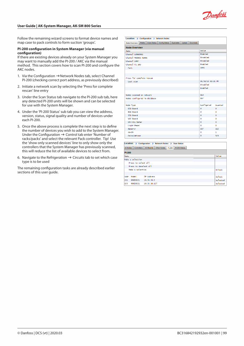
User Guide | AK-System Manager, AK-SM 800 Series
© Danfoss | DCS (vt) | 2020.03 BC316842192932en-001001 | 99
Follow the remaining wizard screens to format device names and map case to pack controls to form suction ‘groups’.
PI-200 configuration in System Manager (via manual configuration)If there are existing devices already on your System Manager you may want to manually add the PI-200 / AKC via the manual method. This section covers how to scan PI-200 and configure the AKC nodes.
1. Via the Configuration Network Nodes tab, select Channel PI-200 (checking correct port address, as previously described)
2. Initiate a network scan by selecting the ‘Press for complete rescan’ line entry
3. Under the Scan Status tab navigate to the PI-200 sub tab, here any detected PI-200 units will be shown and can be selected for use with the System Manager.
4. Under the ‘PI-200 Status’ sub tab you can view the address, version, status, signal quality and number of devices under each PI-200.
5. Once the above process is complete the next step is to define the number of devices you wish to add to the System Manager. Under the Configuration Control tab enter ‘Number of racks/packs’ and select the relevant Pack controller. Tip! Use the ‘show only scanned devices’ line to only show only the controllers that the System Manager has previously scanned, this will reduce the list of available devices to select from.
6. Navigate to the Refrigeration Circuits tab to set which case type is to be used
The remaining configuration tasks are already described earlier sections of this user guide.
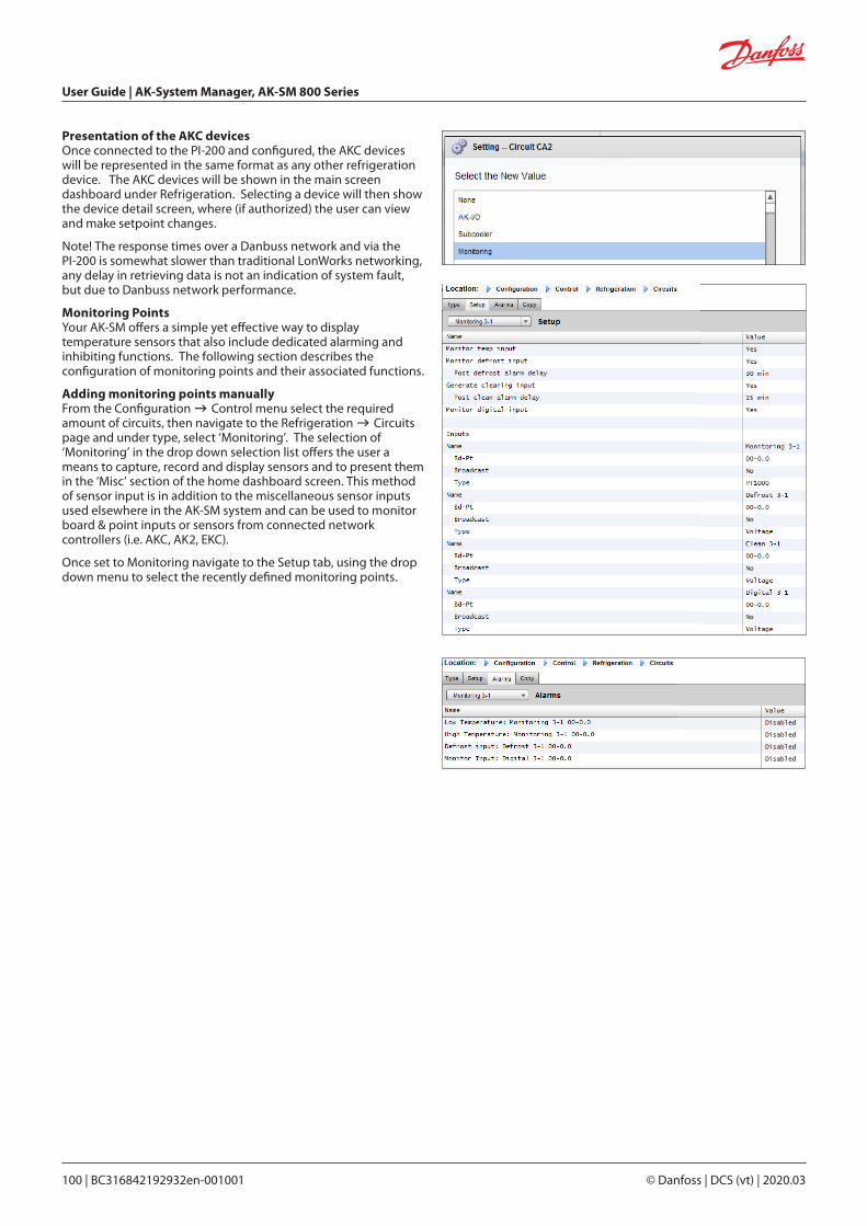
User Guide | AK-System Manager, AK-SM 800 Series
100 | BC316842192932en-001001 © Danfoss | DCS (vt) | 2020.03
Presentation of the AKC devicesOnce connected to the PI-200 and configured, the AKC devices will be represented in the same format as any other refrigeration device. The AKC devices will be shown in the main screen dashboard under Refrigeration. Selecting a device will then show the device detail screen, where (if authorized) the user can view and make setpoint changes.
Note! The response times over a Danbuss network and via the PI-200 is somewhat slower than traditional LonWorks networking, any delay in retrieving data is not an indication of system fault, but due to Danbuss network performance.
Monitoring PointsYour AK-SM offers a simple yet effective way to display temperature sensors that also include dedicated alarming and inhibiting functions. The following section describes the configuration of monitoring points and their associated functions.
Adding monitoring points manuallyFrom the Configuration Control menu select the required amount of circuits, then navigate to the Refrigeration Circuits page and under type, select ‘Monitoring’. The selection of ‘Monitoring’ in the drop down selection list offers the user a means to capture, record and display sensors and to present them in the ‘Misc’ section of the home dashboard screen. This method of sensor input is in addition to the miscellaneous sensor inputs used elsewhere in the AK-SM system and can be used to monitor board & point inputs or sensors from connected network controllers (i.e. AKC, AK2, EKC).
Once set to Monitoring navigate to the Setup tab, using the drop down menu to select the recently defined monitoring points.

User Guide | AK-System Manager, AK-SM 800 Series
© Danfoss | DCS (vt) | 2020.03 BC316842192932en-001001 | 101
To setup monitoring points follow the ‘standard’ method in refrigeration configuration - Main Menu / Configuration / Refrigeration / Add Controls. Answer ‘No’ to the question ‘Pack controller required?’ and navigate to the lower section of the screen and describe how many monitoring sensor points are required (still described as No of case controllers.?’)
Click on the Setup button and then select the Type drop down listChoose Monitoring from the drop down list
Monitor temp inputSelect ‘Yes’ to allow monitoring of a board & point sensor or a sensor via a connected network controller
Defrost InputIf required a Defrost input can be configured. A Defrost input would be used to effectively inhibit the alarms whilst the equipment was in ‘defrost mode’. Once a Defrost input has been configured it can be used in conjunction with further sensor setups (select Existing option for this)No No Defrost input requiredYes Define Defrost inputExisting Pick from previously set Defrost inputsMonitoring setup pageMonitor temp inputSelect ‘Yes’ to allow monitoring of a board & point sensor or a sensor via a connected network controllerPost defrost alarm delayEnter the required time delay that the AK-SM 800 will apply after it has detected a defrost has completed - this can stop nuisance alarmsGenerate Cleaning inputSelect ‘Yes’ if a cleaning input is required (typical example could be voltage or switch). When the assigned switch is made the monitoring point will detect this change of state and will stop any alarms from being transmitted. After the cleaning input is re-set any future alarms will be transmitted - after any post clean alarm delay timer has elapsed.Post clean alarm delayEnter the required time delay that the AK-SM 800 will apply after ithas detected the cleaning input has resetMonitor digital inputSelect ‘Yes’ to allow monitoring of a digital input via a board &point input or a digital input via a connected network controller
Input configurationAfter selecting ‘Yes’ to any of the questions in the upper part of the monitoring configuration screen the resulting input is shown below.
A custom name can be given to each input. For each input enter the corresponding board & point address for local I/O to enter a controller address (see next section for further details on entering controller address). Finally make sure the type is correctly defined for the input (via a drop down list). Page Down to define any alarms for the inputs. Continue to configure any remaining sensors, once complete you can view the sensors in the Evap Overview list, via the Main Menu. As in the generic format simply click on the sensor to view a summary screen. The detail page for the monitoring point contains current status & temperature, the ability to inhibit (stop alarm from occurring) and alarm settings (if configured).
Additional monitoring of dedicated HACCP sensorsUsing the monitoring feature as previously described, dedicated HACCP sensors can be displayed in the main Dashboard overview screen and subsequently logged for history and alarm limits can be assigned.
Danfoss offers a dedicated HACCP sensor (AK-HS 1000) which is supported by some of the evaporator range of AK-CC controllers. In this example the AK-CC 550 evaporator controller will be used to highlight the required steps to monitor this dedicated HACCP sensor. In the example below an amount of (AK-CC 550) evaporator controllers have been defined and a corresponding amount of monitoring points also defined. Once in the monitoring point configuration screen select ‘yes’ to the question ‘Monitor temp input’. Enter a suitable name for the sensor (Case 1 HACCP in this example) and add the relevant controller network address in the form of 001:1 is controller address 1, 002:1 is controller address2... The principle is that by adding the controllers address in the Bd-Pt box the parameters for that controller become available. The final step is to define the HACCP sensor connected to this AK-CC550 (parameter u56 in this example) -this is done via the drop down list against the Pt# line. Page down to set any alarms associated with this sensor and duplicate for the remaining monitoring points - using the relevant controller address to access the parameter list. The defined HACCP sensors will now be seen in the Evap overview screen and can also be set for history collection.
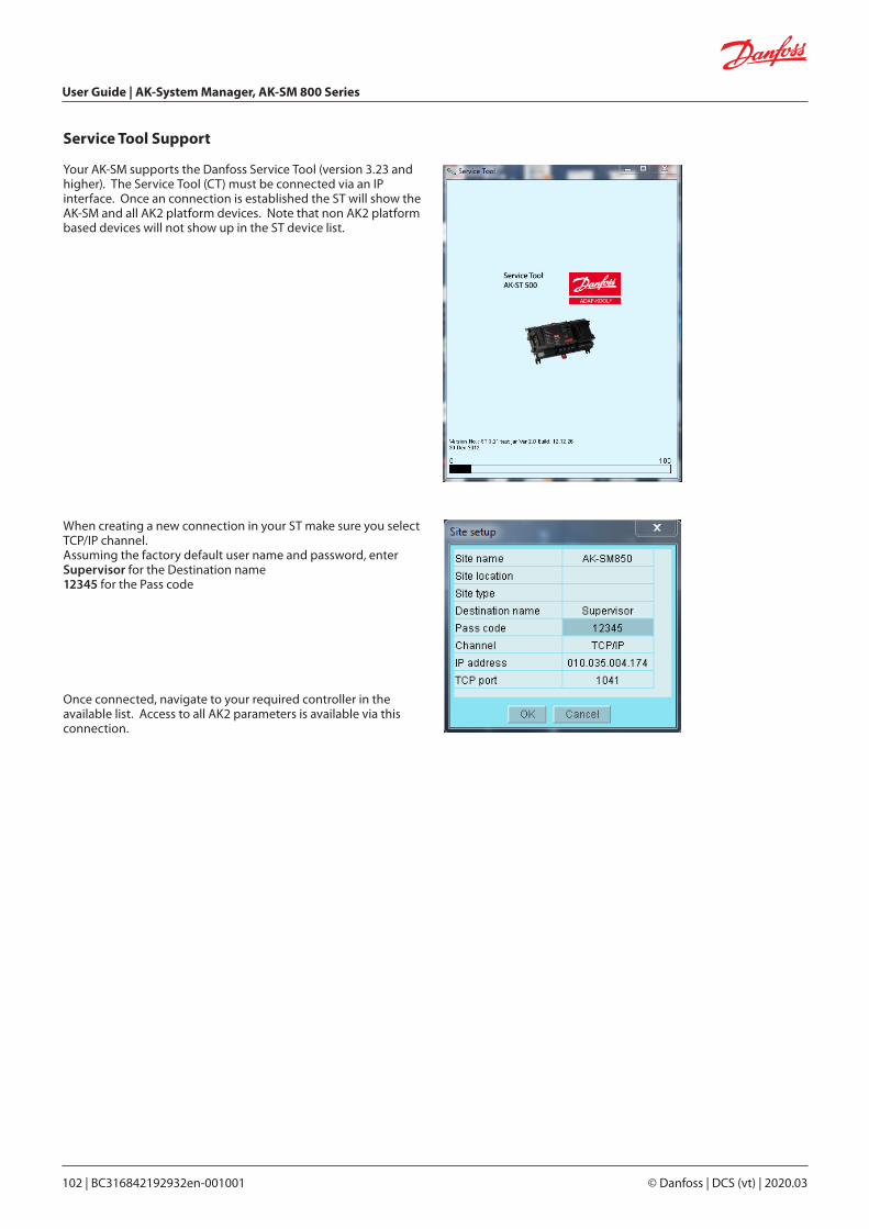
User Guide | AK-System Manager, AK-SM 800 Series
102 | BC316842192932en-001001 © Danfoss | DCS (vt) | 2020.03
Your AK-SM supports the Danfoss Service Tool (version 3.23 and higher). The Service Tool (CT) must be connected via an IP interface. Once an connection is established the ST will show the AK-SM and all AK2 platform devices. Note that non AK2 platform based devices will not show up in the ST device list.
Service Tool Support
When creating a new connection in your ST make sure you select TCP/IP channel.Assuming the factory default user name and password, enterSupervisor for the Destination name12345 for the Pass code
Once connected, navigate to your required controller in the available list. Access to all AK2 parameters is available via this connection.
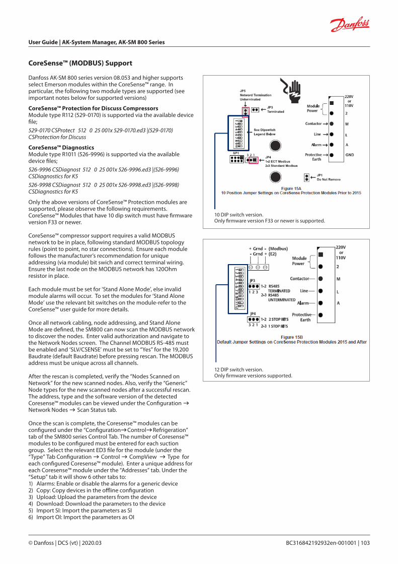
User Guide | AK-System Manager, AK-SM 800 Series
© Danfoss | DCS (vt) | 2020.03 BC316842192932en-001001 | 103
CoreSense™ (MODBUS) Support
Danfoss AK-SM 800 series version 08.053 and higher supports select Emerson modules within the CoreSense™ range. In particular, the following two module types are supported (see important notes below for supported versions)
CoreSense™ Protection for Discuss CompressorsModule type R112 (529-0170) is supported via the available device file;
529-0170 CSProtect 512 0 25 001x 529-0170.ed3 |(529-0170) CSProtection for Discuss
CoreSense™ DiagnosticsModule type R1011 (526-9996) is supported via the available device files;
526-9996 CSDiagnost 512 0 25 001x 526-9996.ed3 |(526-9996) CSDiagnostics for K5
526-9998 CSDiagnost 512 0 25 001x 526-9998.ed3 |(526-9998) CSDiagnostics for K5
Only the above versions of CoreSense™ Protection modules are supported, please observe the following requirements. CoreSense™ Modules that have 10 dip switch must have firmware version F33 or newer.
CoreSense™ compressor support requires a valid MODBUS network to be in place, following standard MODBUS topology rules (point to point, no star connections). Ensure each module follows the manufacturer’s recommendation for unique addressing (via module) bit swich and correct terminal wiring. Ensure the last node on the MODBUS network has 120Ohm resistor in place.
Each module must be set for ‘Stand Alone Mode’, else invalid module alarms will occur. To set the modules for ‘Stand Alone Mode’ use the relevant bit switches on the module-refer to the CoreSense™ user guide for more details.
Once all network cabling, node addressing, and Stand Alone Mode are defined, the SM800 can now scan the MODBUS network to discover the nodes. Enter valid authorization and navigate to the Network Nodes screen. The Channel MODBUS RS-485 must be enabled and ‘SLV/CSENSE’ must be set to “Yes” for the 19,200 Baudrate (default Baudrate) before pressing rescan. The MODBUS address must be unique across all channels.
After the rescan is completed, verify the “Nodes Scanned on Network” for the new scanned nodes. Also, verify the “Generic” Node types for the new scanned nodes after a successful rescan. The address, type and the software version of the detected Coresense™ modules can be viewed under the Configuration Network Nodes Scan Status tab.
Once the scan is complete, the Coresense™ modules can be configured under the “ConfigurationControlRefrigeration” tab of the SM800 series Control Tab. The number of Coresense™ modules to be configured must be entered for each suction group. Select the relevant ED3 file for the module (under the “Type” Tab Configuration Control CompView Type for each configured Coresense™ module). Enter a unique address for each Coresense™ module under the “Addresses” tab. Under the “Setup” tab it will show 6 other tabs to:1) Alarms: Enable or disable the alarms for a generic device2) Copy: Copy devices in the offline configuration3) Upload: Upload the parameters from the device4) Download: Download the parameters to the device 5) Import SI: Import the parameters as SI6) Import OI: Import the parameters as OI
10 DIP switch version.Only firmware version F33 or newer is supported.
12 DIP switch version.Only firmware versions supported.

User Guide | AK-System Manager, AK-SM 800 Series
104 | BC316842192932en-001001 © Danfoss | DCS (vt) | 2020.03
AK-SM 800 Device support guidelines
AK-SM 800 Field bus guidelines
Field bus devices (generic) MODBUS Protocol Info(Baud rate, parity, data bits)
3rd Party MODBUS devices See notes
3rd Party Lon devices (120)
Danfoss MODBUS controller devices (EKC, AKCC, MCX) 120 PARITY_EVEN, 38400, DATA_8_BITS
Danfoss Lon controller devices 120
Danfoss EKC, SLV, WattNode MODBUS (MODBUS) 120 PARITY_EVEN, 19200, DATA_8_BITS
Danfoss SNMP controller devices 160
Danfoss Danbuss via PI-200 (max X4 PI-200 per front end) 120
AK2 Multi-Case controllers (max per front end / no further generic devices allowed)
60
Danfoss gas sensors (DGS) 50 PARITY_EVEN, 38400, DATA_8_BITS
Danfoss ECL heat recovery application P501.11 PARITY_EVEN, 38400, DATA_8_BITS
Danfoss mix (MODBUS/Lon/SNMP) devices 120
Danfoss AK I/O
Danfoss AK I/O Analog Inputs 256
Danfoss AK I/O Analog Outputs (256)
Danfoss AK I/O Digital Inputs 256
Danfoss AK I/O Relay Outputs 256
Comtrol Analog Inputs 256
Comtrol Analog Outputs (256)
Comtrol Digital Inputs 256
Comtrol I/O Relay Outputs 256
Total Digital points 256
Total Analog points 256
3 rd Party
SLV Contact factory
PARITY_EVEN, 19200, DATA_8_BITS
Carlo Gavazzi Power Meters (MODBUS) 80 PARITY_NONE, 9600, DATA_8_BITS
Cutler Hammer Lighting Panels (Lon) PARITY_NONE, 9600, DATA_8_BITS
ComTrol I/O support (via MODBUS port) "IO_SERIAL_FORCE_PARITY_HIGH, 19200, DATA_8_BITS PARITY_NONE, 19200, DATA_9_BITS"
Siemens Lighting Panel (MODBUS) PARITY_NONE, 38400, DATA_8_BITS
Veris Power Meter (MODBUS) PARITY_NONE, 9600, DATA_8_BITS
Square D Lighting Panel (MODBUS) PARITY_NONE, 19200, DATA_8_BITS
EC-Fan (MODBUS) PARITY_EVEN, 19200, DATA_8_BITS
WattNode Plus (MODBUS) , Carlo Gavazzi WM30-AV5, EM 210 PARITY_EVEN, 38400, DATA_8_BITS
Notes
WattNode Plus MODBUS is considered Danfoss MODBUS PARITY_EVEN, 38400, DATA_8_BITS
3rd Party MODBUS devices requires factory validation to confirm capacity (parity/baud rate/system capacity)
Field bus and AK I/O capacities based on AK-SM 850 and 880 (AK-SM 820 has reduced device capacity)
Maximum different controller types in use (active EDF) at one time is 20
AK-SM 800 recommended IT settings
Port Type Use User changeable
80 HTTP Web browser/XML Interface Yes
20 FTP FTP data transfer (FTP is disabled from firmware G08.080) No
21 FTP FTP data server transfer (FTP is disabled from firmware G08.080) No
25 SMTP Used to send e-mail alarms Yes
1041 Proprietary AK-ST500 (service tool) access, allowing Service Tool tunneling to AK2 devices No
3001 XML Alarm port (alarms from unit to alarm receiver e.g. EM800) Yes
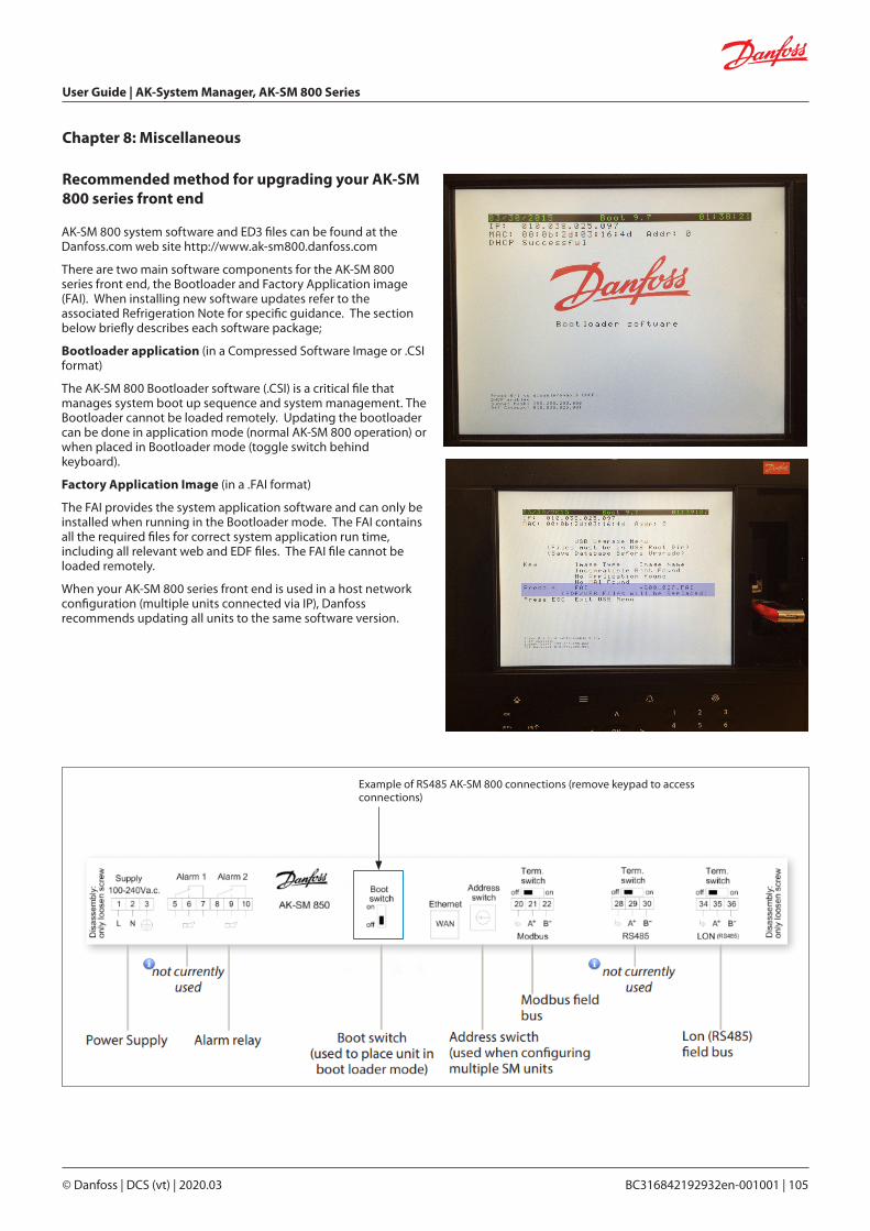
User Guide | AK-System Manager, AK-SM 800 Series
© Danfoss | DCS (vt) | 2020.03 BC316842192932en-001001 | 105
AK-SM 800 system software and ED3 files can be found at the Danfoss.com web site http://www.ak-sm800.danfoss.com
There are two main software components for the AK-SM 800 series front end, the Bootloader and Factory Application image (FAI). When installing new software updates refer to the associated Refrigeration Note for specific guidance. The section below briefly describes each software package;
Bootloader application (in a Compressed Software Image or .CSI format)
The AK-SM 800 Bootloader software (.CSI) is a critical file that manages system boot up sequence and system management. The Bootloader cannot be loaded remotely. Updating the bootloader can be done in application mode (normal AK-SM 800 operation) or when placed in Bootloader mode (toggle switch behind keyboard).
Factory Application Image (in a .FAI format)
The FAI provides the system application software and can only be installed when running in the Bootloader mode. The FAI contains all the required files for correct system application run time, including all relevant web and EDF files. The FAI file cannot be loaded remotely.
When your AK-SM 800 series front end is used in a host network configuration (multiple units connected via IP), Danfoss recommends updating all units to the same software version.
Recommended method for upgrading your AK-SM 800 series front end
Chapter 8: Miscellaneous
Example of RS485 AK-SM 800 connections (remove keypad to access connections)

User Guide | AK-System Manager, AK-SM 800 Series
106 | BC316842192932en-001001 © Danfoss | DCS (vt) | 2020.03
Updating the Bootloader(.CSI) and system application (.FAI) in Bootloader modeThe following workflow describes how to update your AK-SM 800 bootloader and application software. Both Bootloader and FAI are installed whilst your SM 800 is in bootloader mode. Remember to set the Boot Swicth to OFF after completing this task.
1. Gain Supervisor level access by logging into the SM 8002. Backup the system database before proceeding (insert
USB flash drive and option 4, save database) 3. Remove keypad and place Boot switch ON. Replace keypad4. Reset SM800 by power off/on or via the soft reset button
(push in for 5sec), behind front access door5. SM800 will reset into Bootloader mode- insert USB flash drive
and select option 1 to load Bootloader6. After software update, system will reset in Bootloader
mode- verify correct software version. Proceed to update application software (FAI).
7. Ensure / re-insert USB is connected and select option 4 to load FAI
8. System will load FAI and reset (Note! This can take ~20 minutes to complete)
9. Remove keypad and place Boot switch to OFF, replace keypad
10. Reset unit, new SM 800 application is now installed
Updating ED3 filesED3 files are files used by the AK-SM 800 to represent physical devices; typical examples are case and pack controls. The ED3 file allows the user to program offline without having to be connected to any physical device or network. The ED3 files also contain information to support XML information, Optimizations and various device defaults.Typically each new AK-SM 800 series software release (built into the FAI file) will have new and updated ED3 files. However, during mid release cycle, it may be necessary to load new or updated ED3 files to support new devices used in the field. The text below describes the typical action on how to load ED3 files into your AK-SM 800 series front end.
AK-SM 800 system software and ED3 files can be found at the Danfoss.com web sitehttp://www.ak-sm800.danfoss.com
Instructions for loading new ED3 file(S) from RMT1. Use latest RMT tool and via the ‘Log on’ screen connect to your
AK-SM 8002. Once connected, navigate to the ‘File Management’ tab (in the
RMT)3. In the Remote path screen section, navigate to the \edf folder
4. Select the new EDF’s based on your PC, and load/replace into the \edf folder
5. Once all EDF’s have been successfully loaded, the system will need to be re-set. This can be done manually via the units re-set button or under the RMT ‘tools’ menu (Reset Unit)
Note1: To ensure the front end database is fully synced with the controllers settings please perform a controller ‘Upload’ function Flash Drive options (seen in run time application mode) Instructions for loading new ED3 file(S) with USBCopy the ED3 file and the device list to the USB stick and insert the stick in USB port A.User name and password are required to get the USB menu enabled.Option 8. allows to upload the ED3 file and option 9. the LS3 file, which is the device list
Instructions for loading new ED3 file(S) from USBCopy ED3 file and (if needed) the device list to the root folder of the USB stick.Plug in the USB stick into the unit.Press 8 to upload a ED3 file. Press 9 to upload the device list
Option 0: Back up History Log (*.hst)Option 1: The Bootloader file can be updated via USB connection.Option 2: Not applicable for the SM800 seriesOption 3: Not applicable for the SM800 seriesOption 4: Save AK-SM database via USBOption 5: Load AK-SM database via USBOption 6: Save report (txt file format, containing main systemconfiguration details)Option 7: Save Report (txt file format, containing configured system status, not full configuration details)Option 8: Load ED3 fileOption 9: Load LS3 file

User Guide | AK-System Manager, AK-SM 800 Series
© Danfoss | DCS (vt) | 2020.03 BC316842192932en-001001 | 107
Option 2 – RMT access - Connect remotely to SM800 using RMT program to transfer these files
- Set the local path as shown to the folder on your PC where these files are saved to.
- Connect to the SM800 unit and log on with the supervisor access level.
- Upon connection, click on File Management tab and the remote path should display the folders as shown.
- Click on the ‘edf’ folder under the remote path. When you open this folder, the contents will look ‘empty’. Don’t concern with that because the actual files which are resident only appear after an EDF upload (copy) is invoked.
- From the local folder path, click on the files which need to be transferred and then press the right arrow in the middle of the screen to invoke this transfer.
- If you are transferring a large # of files, you must give the SM800 enough process time and then perform a restart to the SM800. (After transferring the Ephrases.tbl file, a minimum of 15 minutes wait time after transfer is required.
- Note: if File Management does not display the
- For offline programming via RMT simulator, be sure to copy these files into the correct Simulator’s EDF folder.
- For further reference, please review the RMT (Remote Management User Guide) or contact technical support for assistance.

User Guide | AK-System Manager, AK-SM 800 Series
108 | BC316842192932en-001001 © Danfoss | DCS (vt) | 2020.03
Document Notes
USCO.PI.R1.E1.02 First document release
USCO.PI.R1.E2.02 Updated document for copy wizard, PI-200 AKC support.
USCO.PI.R1.E3.02 Updated document for history and alarms export.Updated doc for history and alarms export feature in StoreView Desktop.Updated doc for new internal alarm relay option.Updated document to cover software V08_02x.
USCO.PI.R1.E4.02 Updated the following sections: Communication Configuration, Updating Software.
USCO.PI.R1.E5.02 General document update
USCO.PI.R1.E6.02 General document update
USCO.PI.R1.E7.02 Updated the following sections: CoreSense™ (MODBUS) Support, Energy Measurement / Load shed, Coordinated Adaptive Defrost.
USCO.PI.R1.E8.02 Updated document with AK-SM 810 system setup.Updated document for M-Bus support.Updated document in network topology section.
USCO.PI.R1.E9.02 Updated document with connecting to AK-SM 810.Updated document with customized control.Updated document comments about FTP not available.
BC316842192932en-001001 Updated document with diagram of panel mounting where UL Listing is required.Updated document with additional info on Controllers' tab.Updated document with 4G wireless routers.Updated document with ALC (Adaptive Liquid Control).Updated document with Bluetooth® connectivity.Updated document with CoreSense™
Document History
OrderingContact your local Danfoss sales office
Ordering Description / License type Format
Device Platform - RS485 LonWorks®
080Z4006 AK-SM 810 Control RS485 / Convenience store Lon RS485
080Z4004 AK-SM 820 Control RS485-Screen / Convenience store Lon RS485 Screen
080Z4001 AK-SM 850 Control RS485-Screen/ Refrigeration license Lon RS485 Screen
080Z4008 AK-SM 880 Control RS485-Screen / Full store Lon RS485 Screen
080Z4009 AK-SM 880 Control TP78 retro-fit – screen / Full store Lon TP78
080Z4014 AK-SM 800 AL Alarm Logger Ethernet

User Guide | AK-System Manager, AK-SM 800 Series
© Danfoss | DCS (vt) | 2020.03 BC316842192932en-001001 | 109
Glossary of terms
RMT Remote Management Tool
Storeview Desktop Desktop tool for remote control of SM800 series and export data
Viz Visual file. Used in the RMT tool and sent to the AK-SM for graphic Site View
System View Central page of AK-SM that displays all configured control points
Site View Custom graphic page with mapped system parameters
AK I/O: Danfoss AK Input / Output modules
Bd-Pt: Board & Point address location
Alarm Levels: Disabled = no alarm action
Log Only = logs alarm in database - no external action
Normal = Activate alarm output (once)
Severe = Activate alarm output (repeat based on severe repeat time)
Critical = Activate alarm output (repeat based on critical repeat time)
MAI Master Application Image
CSI Compressed Software Image
FAI Factory Application Image
IP Internet Protocol
EDF/ED3 Extended Device File (a file that represents the physical device)
CAT (seen in EDF list) Category (1=Evap, 2=Pack, 8=HVAC, 16=Energy meter, 34=AKD102)
Relative schedule When set a relative schedule will offset against the operating hours (set under config/time)
Host Communications The connection (via Ethernet) of one or more AK-SM units.
The connection between units is known as ‘host network’
Danfoss http://danfoss.com
Danfoss Software http://food-retail.danfoss.com/knowledge-center/software/ak-sm-800/
Veris Industries™ http://www.veris.com/ Carlo Gavazzi™ http://www.carlogavazzi.com/ Continental Control Systems™ http://www.ccontrolsys.com/w/Home
CALM CO2 Adaptive Liquid Management
ALC Adaptive Liquid Control
Bluetooth® The Bluetooth logos and word marks referenced in the Services and Content are the trademarks of
Bluetooth SIG and its affiliates.

© Danfoss | DCS (vt) | 2020.03 BC316842192932en-001001 | 110
AD
AP-
KOO
L®