Embed Size (px)
Citation preview

INCAS BULLETIN, Volume 6, Issue 4/ 2014, pp. 105 – 114 ISSN 2066 – 8201
Walter M337 AK engine monitoring by system EDM-800 in
operation of Air Training and Education Centre
Maria MRAZOVA*
*Corresponding author
University of Zilina, Faculty of Operation and Economics of Transport,
The Air Transport Department
Univerzitna 1, 010 26 Zilina, Slovak Republic
DOI: 10.13111/2066-8201.2014.6.4.10
Abstract: This paper describes the process of the M337 engine monitoring by the Engine Data
Management 800 which is mounted on six aircraft of Air Training and Education Centre. This is the
most advanced and accurate piston engine-monitoring system on the market that uses the latest
microprocessor technology to monitor critical engine parameters in order to measure parameters as
cylinder head temperature and exhaust gas temperature to evaluate each cylinder performance alone.
These parameters are monitored during these flight regimes – take off, climb and cruise. Monitoring
of the mentioned parameters will help us to increase the economy of the aircraft and also its
operation’s reliability.
Key Words: piston engine, EDM-800, Exhaust Gas Temperature, Cylinder Head Temperature
1. INTRODUCTION
Air Training and Education Centre is located at the international Airport Zilina– Dolny
Hricov, in the north-western part of Slovak Republic. The Flight school of University of
Zilina was established in 1974 as the only civil school in former Czechoslovakia with the
aim to provide civil pilot training. Air Training Centre as an independent organisation was
established on 1st September 2002 in line with JAR-FCL 1.
Nowadays, the Air Training and Education Centre provides flight training up to ATP
licence. The University of Zilina is a holder of the Certification on Flight Training
Organisational approval (SK.ATO.01) in accordance with the JAA/EASA standards and
aircraft maintenance centre approval (SK.MF.006, SK.MG.025). It also provides specialised
courses such as, courses for Slovak Air Force, Security courses – NSC, and ATC-ATCO
(Phase I/II) courses. Air Training and Education Centre uses both, single and twin engine
aircraft for professional pilot training. This paper deals with the selected types of aircraft
(with M337 engine) where EDM-800 monitoring system is installed for the purpose of
monitoring the critical engine parameters, focusing on EGT (Exhaust Gas Temperature) and
CHT (Cylinder Head Temperature) analysis.
2. WALTER M337 AK ENGINE OVERVIEW
Air Training and Education Centre uses these airplanes powered by M337 engine – Zlin 43,
Zlin 142 and L-200D Morava for the pilot training course. More precisely we refer to the
following aircraft, registered as: Z43 OM-KOZ, Z43 OM-LOW, Z142 OM-KNO, Z142

Maria MRAZOVA 106
INCAS BULLETIN, Volume 6, Issue 4/ 2014
OM-PNU, Z142 OM-SNY and Z142 OM-UNA. For the purpose of this research we will use
just Zlin 43 aircraft. The Avia M 337 originally Walter M337 engine (Figure 1) is an
inverted six-cylinder air-cooled inline piston engine. It was developed as a six-cylinder
derivative of the four-cylinder M332 engine.
It was made by the Czechoslovak company and went into production in 1960. An un-
supercharged version of the M337 is designed M137, in 1964 the production was
transformed to Avia company and in 1992 to LOM Prague – the main designer of inverted
piston engines.
Figure 1. Illustration of the Zlin 43 aircraft – left M337 engine - right (Taylor, 1980)
“The first four-cylinder engine M332A was launched in 1992 and later, its derivation
M332A has become the engine M332 AK which has no time limitation for inverted flight.
The redesigned engine oil system enables, during inverted flight, back oil direction into oil
tank conformable to M337 AK engine” (Tizek, 1992).
In addition, M337 engine is used for training aircraft for flight school or for commercial
small, light-weight aircraft. The advantage of this engine is that it is characterised by a small
frontal area, low weight, economic efficiency and simple maintenance.
Table 1 below illustrates the basic features of different variants of M 337 engine.
Table 1. Overview of the variants of the M337 engine (Taylor, 1980)
Variants Characteristic feature
M 337 A Basic supercharged engine (not for aerobatics purpose)
M 337 R Modified for pusher installation
M 337 AK Modified oil system (use for unlimited inverted flying, also snap
aerobatics permitted
M 337 AK1 M 337 AK fitted with alternator instead of generator
M 337 B Increased maximum running speed (3000 rpm) and power (173 kW)
M 337 BK Aerobatic version of M 337 B
M 337 C Increased compression ratio to 185 kW
According to (Taylor, 1980) general specifications of the M337 engine are illustrated in
Table 2 below.
Table 2. Overview of the general characteristics of M337 (Taylor, 1980)
General characteristics Components Performance
Type 6-cylinder
inverted air-
cooled
supercharged
inline engine
Valve train 2 camshaft operated
valves per cylinder,
sodium filled exhaust
valve
Power
output
157 kW
at 2,750
rpm
(take-off)

107 Walter M337 AK engine monitoring by system EDM-800 in operation of Air Training and Education Centre
INCAS BULLETIN, Volume 6, Issue 4/ 2014
Bore 105 mm Supercharger Centrifugal
Stroke 115 mm Fuel system Low-pressure fuel
injection
Displacement 5.97 L Fuel type Min 72-78 Octane
Length 1,410 mm Oil system Dry sump pressure
system
Width 472 mm Cooling
system
Air cooled
Height 628 mm
EDM-800 MONITORING SYSTEM
EDM-800 (Figure 2) is made by J.P. Instruments, Inc. one of the instruments leading
producers in this field. The system has been installed on selected aircraft of the Air training
and Education Centre (Zlin 43, Zlin 142) in order to measure parameters of the engine and
also to increase safety and efficiency of pilot training. The reason to choose this instrument
was linked to the need of the instrument that is able to work in the background without
affecting the other primary instruments.
Figure 2. Illustration of the monitoring system EDM-800 instrument [author]
This system is the most advanced instrument ever produced for piston engine-monitoring. It
is able to monitor 29 functions every 6 seconds for up to 25 hours or even every minute for
550 hours.
The instrument later records those parameters in a set time interval from 6 to 500
seconds. Automatically, if the monitored parameters exceed the limits, the pilot is warmed
by a special signal.
This system provides important information to the user regarding EGT and CHT for all
cylinders (the data is shown on graphical and digital displays). These two parameters will be
important for the purpose of our research, though the system is able to monitor other
parameters1, such as oil pressure and temperature, compressor discharge temperature, turbine
inlet temperature, OAT, MAP or RPM.
1 J.P. Instruments Inc. produces many variants of EDM, such as EDM 700, 711 or 800. The product features are
illustrated in Table 3.

Maria MRAZOVA 108
INCAS BULLETIN, Volume 6, Issue 4/ 2014
Table 3. Overview of the basic features of EDM-800 monitoring system (Inc., 2007)
Feature of EDM-800 Hands-free, automatic scanning (711: primary only)
All programming done from the Front Panel
Lean Find TM
finds the first and last cylinder to peak
with true peak detection - eliminates a false peaks
Displays both leaned temperature below peak and peak
Battery voltage with alarm
24 Programmable alarm limits
Normalize view
DIF low to high EGT with alarm
EGTs to stable 1°F resolution
Shock cooling monitored on every cylinder
User selectable index rate
Fast response probes
Non-volatile long term memory
Records and stores data up to 30 hours
Post-flight data retrieval
Data retrieval software
Fuel Flow
Solid-state rotor fuel flow transducer
Fuel quantity in gallons, kilograms, litres, or pounds
Low fuel quantity alarm
Low fuel time alarm
GPS interface
Instantaneous fuel flow rate
Total amount of fuel consumed
Total fuel remaining
Time to empty at the current fuel flow rate
Displays % horsepower and RPM
Automatically calculates percent horsepower
However, another important decision which was necessary to make refers to the
emplacement of this instrument on the aircraft. Firstly, a Turn Indicator, Slip Indicator and
Bank indicator on the instructor’s side of the instrument panel were removed and a fuel
gauge was put into the position where the Turn and Slip Indicator were previously placed.
The free space where the fuel gauge was located had become the place for the EDM-800
monitoring system (as can be seen in Figure 3) and the diameter of the instrument was 2 ¼
inch (Kříž et al, 2010).
Figure 3. EDM-800‘s emplacement on the instrument panel in Zlin 43 (Kříž et al, 2010)
109 Walter M337 AK engine monitoring by system EDM-800 in operation of Air Training and Education Centre
INCAS BULLETIN, Volume 6, Issue 4/ 2014
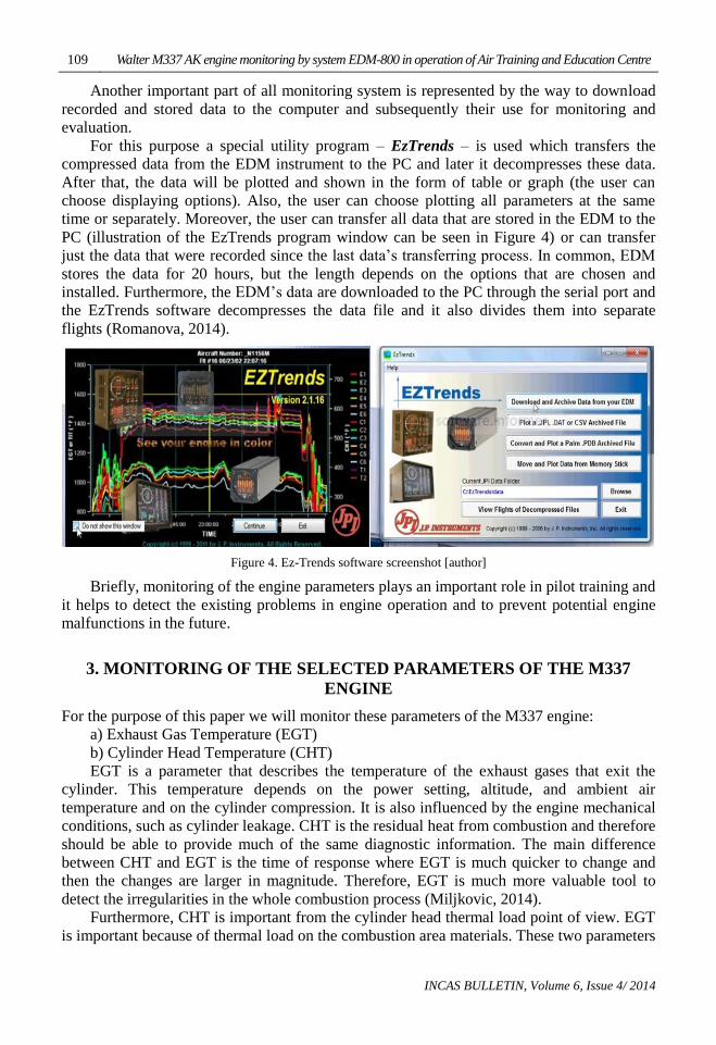
Another important part of all monitoring system is represented by the way to download
recorded and stored data to the computer and subsequently their use for monitoring and
evaluation.
For this purpose a special utility program – EzTrends – is used which transfers the
compressed data from the EDM instrument to the PC and later it decompresses these data.
After that, the data will be plotted and shown in the form of table or graph (the user can
choose displaying options). Also, the user can choose plotting all parameters at the same
time or separately. Moreover, the user can transfer all data that are stored in the EDM to the
PC (illustration of the EzTrends program window can be seen in Figure 4) or can transfer
just the data that were recorded since the last data’s transferring process. In common, EDM
stores the data for 20 hours, but the length depends on the options that are chosen and
installed. Furthermore, the EDM’s data are downloaded to the PC through the serial port and
the EzTrends software decompresses the data file and it also divides them into separate
flights (Romanova, 2014).
Figure 4. Ez-Trends software screenshot [author]
Briefly, monitoring of the engine parameters plays an important role in pilot training and
it helps to detect the existing problems in engine operation and to prevent potential engine
malfunctions in the future.
3. MONITORING OF THE SELECTED PARAMETERS OF THE M337
ENGINE
For the purpose of this paper we will monitor these parameters of the M337 engine:
a) Exhaust Gas Temperature (EGT)
b) Cylinder Head Temperature (CHT)
EGT is a parameter that describes the temperature of the exhaust gases that exit the
cylinder. This temperature depends on the power setting, altitude, and ambient air
temperature and on the cylinder compression. It is also influenced by the engine mechanical
conditions, such as cylinder leakage. CHT is the residual heat from combustion and therefore
should be able to provide much of the same diagnostic information. The main difference
between CHT and EGT is the time of response where EGT is much quicker to change and
then the changes are larger in magnitude. Therefore, EGT is much more valuable tool to
detect the irregularities in the whole combustion process (Miljkovic, 2014).
Furthermore, CHT is important from the cylinder head thermal load point of view. EGT
is important because of thermal load on the combustion area materials. These two parameters
Maria MRAZOVA 110
INCAS BULLETIN, Volume 6, Issue 4/ 2014
tell us how the piston engine works, what is the fuel mixture, but at the same time it indicates
any abnormality in the combustion process.
It is important to set optimal mixture, which is chosen according to the selected mode of
operation and the desired output. Slightly richer mixture, slightly increases engine
performance (all supplied oxygen is burned) and the fuel excess can lead to the cooling of
the combustion process. On the other hand, the fuel consumption can be significantly higher
than at a slightly leaner mixture.
Leaner mixture will cause a decrease in performance (because not all oxygen is burned),
but the increased temperature can lead to damage to the engine itself (Hrčka, 2007),
(Mikalsen et al, 2007).
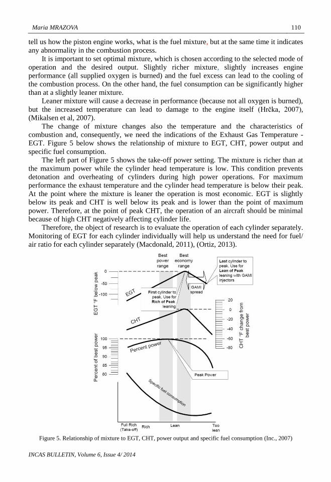
The change of mixture changes also the temperature and the characteristics of
combustion and, consequently, we need the indications of the Exhaust Gas Temperature -
EGT. Figure 5 below shows the relationship of mixture to EGT, CHT, power output and
specific fuel consumption.
The left part of Figure 5 shows the take-off power setting. The mixture is richer than at
the maximum power while the cylinder head temperature is low. This condition prevents
detonation and overheating of cylinders during high power operations. For maximum
performance the exhaust temperature and the cylinder head temperature is below their peak.
At the point where the mixture is leaner the operation is most economic. EGT is slightly
below its peak and CHT is well below its peak and is lower than the point of maximum
power. Therefore, at the point of peak CHT, the operation of an aircraft should be minimal
because of high CHT negatively affecting cylinder life.
Therefore, the object of research is to evaluate the operation of each cylinder separately.
Monitoring of EGT for each cylinder individually will help us understand the need for fuel/
air ratio for each cylinder separately (Macdonald, 2011), (Ortiz, 2013).
Figure 5. Relationship of mixture to EGT, CHT, power output and specific fuel consumption (Inc., 2007)

111 Walter M337 AK engine monitoring by system EDM-800 in operation of Air Training and Education Centre
INCAS BULLETIN, Volume 6, Issue 4/ 2014
The parameters will be investigated in 3 power settings, during take-off, climb and
cruise.
These modes are standardized in terms of engine speed and manifold pressure, so the
results will be well comparable for certain flights or for a specific examined period.
To investigate the single power output would be insufficient because the engine power
setting change also changes the thermal load.
The following table gives the engine settings with corresponding propeller RPM and
manifold pressure for Zlin 43.
Table 4. Flight regimes and corresponding engine settings [author]
ZLÍN 43
Flight regimes RPM MAP (at)
Take-off 2750 1,2
Max. continuous 2600 1,0
Max. cruise 2400 0,92
Economic 2300 0,84
M337 piston engine has 6 cylinders, and the aim of this monitoring will be to learn how
each cylinder works separately during the selected flight regimes.
The result will help us to find out how to manage the economic operation of the engine
and at the same time it also prolongs its life. The values will be monitored during both the
summer and winter operation.
3.1 Analysis of the data gathered from the EDM-800 system in relation to
the selected flight regimes
This subchapter describes the gathered average values of the EGT and CHT during the
selected flight regimes of Zlin 43 aircraft with registrations Zlin 43 OM-KOZ and Zlin 43
OM-LOW that are used for pilot training in the Air Training and Education Centre.
Table 5 and Table 6 below illustrate the measured values of the engine during both the
winter and summer operations for Zlin 43 OM-KOZ and Zlin 43 OM-LOW aircraft.
Table 5. Flight regimes and values of the EGT for Zlin 43 OM-KOZ [author]
Maria MRAZOVA 112
INCAS BULLETIN, Volume 6, Issue 4/ 2014
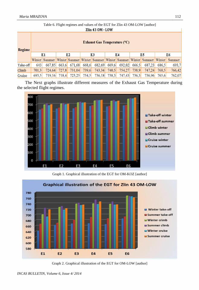
Table 6. Flight regimes and values of the EGT for Zlin 43 OM-LOW [author]
The Next graphs illustrate different measures of the Exhaust Gas Temperature during
the selected flight regimes.
Graph 1. Graphical illustration of the EGT for OM-KOZ [author]
Graph 2. Graphical illustration of the EGT for OM-LOW [author]
113 Walter M337 AK engine monitoring by system EDM-800 in operation of Air Training and Education Centre
INCAS BULLETIN, Volume 6, Issue 4/ 2014
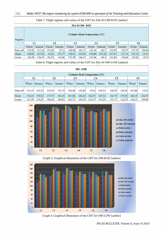
Table 7. Flight regimes and values of the CHT for Zlin 43 OM-KOZ [author]
Table 8. Flight regimes and values of the CHT for Zlin 43 OM-LOW [author]
Graph 3. Graphical illustration of the CHT for OM-KOZ [author]
Graph 4. Graphical illustration of the CHT for OM-LOW [author]
Maria MRAZOVA 114
INCAS BULLETIN, Volume 6, Issue 4/ 2014
Briefly, based on the tables and graphs from the previous paragraph, we can summarise
that in cruise regime the engine runs at the highest EGT and CHT at the same time.
These values result from the leanest mixture. On the other hand, in cruise flight regime
the mixture is richer because of engine cooling and regular operation and because of this,
CHT and EGT are lowest.
4. RESULTANT CONCLUSIONS
The goal of this paper was to monitor the engine parameters by analysing the data recorded
by EDM-800.
The monitoring presented in this thesis contains the statistical analysis of the engine
parameters for different engine working regimes and the comparison of the parameters of
two different engines. The data were presented in tables and graphs.
While analysing the data, some deviations were noticed. The most common problems were:
• CHT on some cylinders was higher than on the other ones. Possible cause: the ring
can be broken or there’s something wrong with the cooling system and the cold air doesn’t
get to some cylinders.
• There is a big difference between the highest and the lowest EGT. Possible cause:
injection nozzles are dirty or there’s a problem with the induction system.
However, the causes mentioned above are only theoretical and further analysis is required.
Briefly, the EDM-800 system also helps the aircraft maintenance at the Air training and
education centre of the University of Zilina to determine and localize malfunctioning
components of M337 piston engines.
ACKNOWLEDGEMENTS
This paper is published as one of the scientific outputs of the project: Implementation of
scientific research knowledge to the Air Transport ITMS 26220220010.
We support research activities in Slovakia/ Project is co-financed by EU.
REFERENCES
[1] * * * Hrčka (2007, September 8). Aeroweb. Retrieved on September 27, 2014 from
http://www.aeroweb.cz/clanek.asp?ID=826&kategorie=3
[2]* * * Inc., J. I. (2007). J.P. Instruments. Pilot’s Guide. Retrieved on October 20, 2014, from
https://www.jpinstruments.com/wp-content/uploads/2012/10/PG-EDM-800-Rev-W.pdf
[3 Mikalsen et al, A review of free-piston engine history and applications, Applied Thermal Engineering, Volume
27, Issues 14-15, Pp.2345-2348, 2007.
[4] Kříž, Implementation of the EDM-800 monitoring system. Conference – New trends in civil aviation. Zilina,
2011.
[5] Macdonald, Owner Assisted Aircraft Maintenance, Alpha Zulu LLc. Eden Prairie, 160 p, 2011.
[6] Romanova, Monitoring of M137 aicraft engine. Bachelor thesis. Zilina, 2014.
[7] Taylor, Jane’s all the world’s aircraft 1980-81. London: Jane’s. pp. 120-125, 1980.
[8] Tizek, LOM Prague piston engines and propellers production, 1992.
[9] Miljkovic, Aircraft Piston Engine Fault Detection Based on Uniformity of Cylinder Head, Exhaust Gas and
Turbochargers Temperatures, ECNDT Conference, Prague, 2014.
[10] Ortiz et al, Failure analysis of the engine cylinder of a training aircraft, Engineering Failure Analysis,
Volume 35, Pp. 687-888, 2013.