Embed Size (px)
Citation preview

AIRTEK
H e a t l e s s A i r D r y e r s
T W S e r i e s
PREMIUM PRODUCTS FOR INDUSTRY

Airtek Heatless Dryers remove water vapor from compressed air through aprocess known as Pressure Swing Adsorption. Pressure dew points ranging from-40OF to -100OF are attained by directing the flow of saturated compressed airover a bed of desiccant. The most commonly used desiccant is activated alumina,a spherical shaped, hygroscopic material, selected for its consistent size, shapeand extreme surface to mass ratio. This physically tough and chemically inertmaterial is contained in two separate but identical pressure vessels commonlyreferred to as “dual” or “twin” towers. As the saturated compressed air flows upthrough the “on line” tower, its moisture content adheres to the surface of thedesiccant. The dry compressed air is then discharged from the chamber into thedistribution system.
A solid state controller automatically cycles the flow of compressed air betweenthe towers, while the “on line” tower is drying, the “off line” tower isregenerating. Regeneration, sometimes referred to as purging, is the process bywhich moisture accumulated during the “on line” cycle is stripped away duringthe “off line” cycle. As low pressure dry purge air flows gently through theregenerating bed, it attracts the moisture that had accumulated on the surface ofthe desiccant during the drying cycle and exhausts it to the atmosphere.
To protect the desiccant bed from excess liquid, all Airtek heatless dryers aredesigned to work with the natural pull of gravity. By directing the saturated
air into the bottom of the “on line” tower and flowing up throughthe bed, liquid condensate caused by system upset, is kept awayfrom the desiccant and remains at the bottom of the tower where
it can be easily exhausted during the regeneration cycle.Counter flow purging ensures optimum performance by
keeping the driest desiccant at the discharge end of thedryer.
Moisture load, velocity, cycle time and contact timedetermine tower size and the amount of desiccant. Toensure design dew point, each tower is carefully sized to
allow a minimum of 5.5 seconds of contact. Toprevent desiccant dusting and bedfluidization, air flow velocities are kept below50 feet per minute. The dryer can cycle foryears without changing the desiccant.
Heatless dryers in general are the mostreliable and least expensive of all desiccanttype dryers. Airtek Heatless Dryers are themost energy efficient thanks to standardfeatures like, “Variable Cycle Control”,“CycleLoc”, and “ProPurge”.
Heatless Air Dryer Operation
2
TW600 with package “E”(Cutaway showing air flow)

Valves
3
Dryers 75 to 800 SCFM are equipped with our time-proven and dependablenon-lubricated switching valves. The independent, air operated valves arespecifically designed for compressed air service. They are resistant to desiccantdust and can be maintained without being removed from the dryer.
Non-Lubricated Valves
While other dryers use a manual valve for purge control, Airtek provides a PurgeFlow Regulator. Due to system pressure fluctuation, dryers equipped withmanual purge valves waste air and energy by over-purging when systempressure is high and sacrifice performance by under-purging when systempressure is low. Manual purge valves do not compensate for system pressurevariance. Airtek’s exclusive Purge Flow Regulator saves energy and ensuresperformance by maintaining optimum purge regardless of system pressure. Toprevent the purge flow from fluctuating and to discourage unauthorizedtampering, the Purge Flow Regulator can be locked into position.
Purge Flow Regulator
High performance, Rotary Actuated Switching Valves are standard on dryers1,000 SCFM and larger. These premium, air operated butterfly valves arespecifically designed to allow higher flow with lower associated pressure drop.They provide more opening and closing force compared to other types of valves.An indicator shows the “open/closed” position of the valve and service can beperformed without disturbing dryer piping.
These valves are so reliable, they carry a three-year factory warranty.
Rotary Actuated Valves
Master Control
4
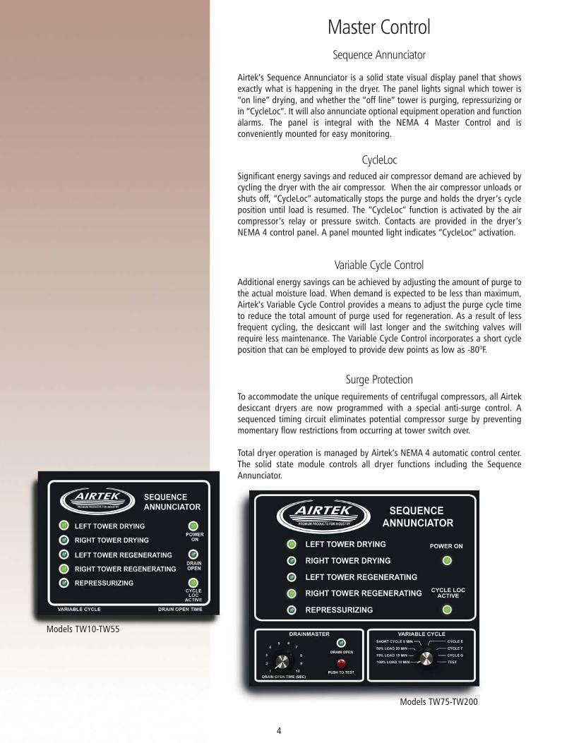
Airtek’s Sequence Annunciator is a solid state visual display panel that showsexactly what is happening in the dryer. The panel lights signal which tower is“on line” drying, and whether the “off line” tower is purging, repressurizing orin “CycleLoc”. It will also annunciate optional equipment operation and functionalarms. The panel is integral with the NEMA 4 Master Control and isconveniently mounted for easy monitoring.
Significant energy savings and reduced air compressor demand are achieved bycycling the dryer with the air compressor. When the air compressor unloads orshuts off, “CycleLoc” automatically stops the purge and holds the dryer’s cycleposition until load is resumed. The “CycleLoc” function is activated by the aircompressor’s relay or pressure switch. Contacts are provided in the dryer’sNEMA 4 control panel. A panel mounted light indicates “CycleLoc” activation.
Sequence Annunciator
CycleLoc
Additional energy savings can be achieved by adjusting the amount of purge tothe actual moisture load. When demand is expected to be less than maximum,Airtek’s Variable Cycle Control provides a means to adjust the purge cycle timeto reduce the total amount of purge used for regeneration. As a result of lessfrequent cycling, the desiccant will last longer and the switching valves willrequire less maintenance. The Variable Cycle Control incorporates a short cycleposition that can be employed to provide dew points as low as -80OF.
Variable Cycle Control
To accommodate the unique requirements of centrifugal compressors, all Airtekdesiccant dryers are now programmed with a special anti-surge control. Asequenced timing circuit eliminates potential compressor surge by preventingmomentary flow restrictions from occurring at tower switch over.
Total dryer operation is managed by Airtek’s NEMA 4 automatic control center.The solid state module controls all dryer functions including the SequenceAnnunciator.
Surge Protection
Models TW10-TW55
Models TW75-TW200

Pro-Purge Demand Control
Airtek’s Pro-Purge is standard equipment on Heatless Air Dryers 250 scfmand larger. It is an advanced “Proportional Demand Controller” that savesenergy by automatically regulating the purge cycle in response to actualloads. Moisture loads fluctuate throughout the day and rarely reach maxi-mum moisture levels, and therefore, waste energy by regenerating moreoften than is necessary. The Pro-Purge monitors actual compressed airmoisture levels and prevents cycle advancement until the designedsaturation is read.
Pro-Purge Operation
The Pro-Purge Panel lights indicate:Power Saver Mode/Demand Control active “ON” LED.
“OFF” LED indicates the Pro-Purge Demand Control isdeactivated and the dryer is functioning in the fixed cycle default mode.
LED Display Panel
The High Dew Point Alarm is activated when dew points rise above -20OF.It would also activate in the event of a short circuit or should the sensorbecome disconnected. Dry contacts for an external alarm are provided.
High Dew Point Alarm
The Pro-Purge module can be retrofitted to all older Airtek Heatless AirDryers
Retrofit Capability
5
Models TW250-TW6000
6
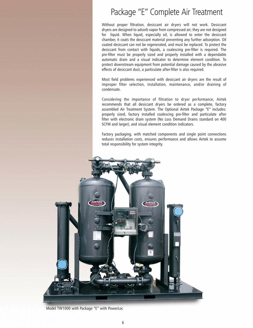
Without proper filtration, desiccant air dryers will not work. Desiccantdryers are designed to adsorb vapor from compressed air; they are not designedfor liquid. When liquid, especially oil, is allowed to enter the desiccantchamber, it coats the desiccant material preventing any further adsorption. Oilcoated desiccant can not be regenerated, and must be replaced. To protect thedesiccant from contact with liquids, a coalescing pre-filter is required. Thepre-filter must be properly sized and properly installed with a dependableautomatic drain and a visual indicator to determine element condition. Toprotect downstream equipment from potential damage caused by the abrasiveeffects of desiccant dust, a particulate after-filter is also required.
Most field problems experienced with desiccant air dryers are the result ofimproper filter selection, installation, maintenance, and/or draining ofcondensate.
Considering the importance of filtration to dryer performance, Airtekrecommends that all desiccant dryers be ordered as a complete, factoryassembled Air Treatment System. The Optional Airtek Package “E” includes:properly sized, factory installed coalescing pre-filter and particulate afterfilter with electronic drain system (No Loss Demand Drains standard on 400SCFM and larger), and visual element condition indicators.
Factory packaging, with matched components and single point connectionsreduces installation costs, ensures performance and allows Airtek to assumetotal responsibility for system integrity.
Package “E” Complete Air Treatment
Model TW1000 with Package “E” with PowerLoc

Package Schematics
Filters
7
Includes dryer with factory installed pre-filter and after-filter.
Package “E”
Includes dryer with factory installed pre-filter and after-filter with systembypass.
Package “EB”
Includes dryer with factory installed dual selectable pre-filters and singleafter-filter.
Package “EC”
Includes dryer with factory installed dual selectable pre and after-filters.
Note: Consult factory for other package configurations
Package “ED”
DRYER AFPF DRYER AFPF
DRYER AFPF DRYER AFPF
AFDRYERDRYER AF
PFPF
PFPF
AF
AF
AF
AF
DRYERDRYER
PFPF
PFPF
Airtek Package “E” systems match our TW Heatless dryers with Airtek highperformance filters. In-line filters (JW) are used on systems 100 through300 SCFM and two stage (JL) severe duty filters are used on systems 400SCFM and larger.
The coalescing pre-filter is installed at the dryer inlet. It protects the dryerby removing liquids and reducing the contamination level of thecompressed air to .01 PPM by weight. The element is DOP rated at99.9+% efficient in the 0.3 to 0.6 micron range. An integrated digitalindicator is provided to determine element condition. An electronic drainvalve is provided on systems 100 through 300 SCFM to ensure properdrainage. On systems 400 SCFM and larger a zero air loss demand drainis provided. The drain controller includes push to test, drain alarm, andcommon alarm contact.
To protect downstream equipment from desiccant dust a particulateafter-filter is installed at the dryer discharge. The after-filter element isdesigned to remove solid particulates from compressed air. The hybridpleated filter media provides high dirt retention, low pressure drop, andlong element life. The element is 100% effective in removing particles 0.9micron and larger. A integrated digital element condition indicator is alsoprovided.
Note: Optional Mist Eliminators are available as extra protection forstandard packages.
Air Out
2nd StageDrain
Drain Valve
DemandDrain Valve 1st Stage
Drain
Air InFirst Stage
Quiet Zone
Second Stage
400 SCFM and larger

Energy Savings and Operating Cost Reduction
PowerLoc Energy Management System
PowerLoc automatically adjusts energy use to actual moisture load. Moistureloading is affected by inlet temperature, pressure, relative humidity and flow.These conditions vary throughout the day and rarely combine in such a manneras to produce maximum moisture loads. An inlet temperature reduction of just20OF (-7OC) will reduce the moisture load by almost 50%. Desiccant dryers arenormally sized for “worst case” operation with the cycle fixed to accommodatemaximum moisture loads. Because the fixed cycle does not compensate forfluctuating loads, dryers not equipped with PowerLoc or Pro-Purge wasteenergy by regenerating more often than necessary. PowerLoc eliminates theunnecessary use of energy by delaying regeneration until the total designmoisture load is achieved. The system monitors actual moisture loading andlimits the number of purge cycles accordingly.
At $0.08 per Kwh, the PowerLoc would save over $10,000 annually when usedwith a 1,000 SCFM heatless dryer operating at 70% load for 8,000 hours at anaverage inlet temperature of +85OF (29OC). Digital dew point control providesfor additional energy savings by allowing the operator to select higher dewpoints when appropriate. The moisture probe is contained in and protected bya rugged, stainless steel housing that also contains an electronics package forcontinuous self calibration, temperature compensation, and signal stabilization.Due to less frequent cycling, switching valves and desiccant will last longer andrequire less maintenance.
The PowerLoc ceramic sensor is made from state-of-the-art metalized ceramicand replaces traditional materials such as aluminum, silicon and hygroscopicsalts. This fast response sensor is made from a ceramic tile that is plated andvapor deposited to form a surface that is very sensitive to small changes inwater vapor pressure.
The proprietary coating processes make the ceramic sensor inherently faster torespond than other impedance or capacity sensors currently available. Theceramic sensor features the latest digital technology with calibration data storeddirectly in the sensor’s memory, and is equipped with a built-in thermistor forautomatic temperature compensation. The PowerLoc is traceable to the NationalInstitute of Standards and Technology. A certificate of traceability is available.
The PowerLoc ceramic sensor is protected by an 80 micron sintered metal guardand is enclosed in a rugged, stainless steel housing with a pressure rating of5,000 PSIG. This housing increases the sensor’s ability to withstand reasonableshock and vibration.
8
Effects of Inlet Temperature on Moisture Load
.47 .55 .65 .75 .87 1.0
75OF (24OC)
80OF (27OC)
85OF (29OC)
90OF (32OC)
95OF (35OC)
100OF (38OC)
Factor
Inle
t Tem
pera
ture

Typical Compressed Air System
ISO Classification
9
ISO Class 1-4-1 C6
ISO Class 1-4-1
CT - ColdTrapTM Refrigerated DryerECP-Elite Series with
ColdPoint CoaslescingTM
SC-SmartCycleTM Refrigerated DryerES-Elite Series Refrigerated Dryer
TD-Single Tower Blower Purge Desiccant(Filters Standard)
TW - Heatless DesiccantTWP-Externally Heated
DesiccantTWB-Blower Purge
Desiccant
TW - Heatless DesiccantTWP-Externally Heated
DesiccantTWB-Blower Purge
Desiccant
C6
ISO Class 1-3-1
F
C6
ISO Class 1-2-1 or 1-1-1
-40oF PDP/ -100oF PDP
-40oF PDP/ -100oF PDP
F
C10 C6
ISO Class 1-2-1 or 1-1-1
F A
Compressed Air Source
Coalescer - Standard C6General Plant Air: High efficiency coalescing applications when removal of liquid andsuspended fines are required.
Air Dryer System: Pre-filter protection for desiccant type air dryers. Maintains dryerefficiency by preventing coating of bed with oil or varnish. Removes condensed water,leaving only vapors for dryer to remove. Prevents catastrophic oil flood should separator fail.
Coalescer - C8General Plant Air: Good air coalescing efficiency in combination with high flow rate andlong element life. Generally used for plant air source system. Separate pre-filter not requiredfor “normal to light” particulate loading.
Air Dryer System: Pre-filter protection for refrigerated type air dryers. Maintains dryerefficiency by preventing coating of coils with oil or varnish. Removes condensed water,leaving only vapors for dryer to remove. Prevents catastrophic oil flood should separator fail.
Coalescer - C10General Plant Air: Pre-coalescer for heavy liquid aerosol loads. Pre-filter for grades 6 and 8when varnishing occurs due to high temperature operation with hydrocarbon oil.
Air Dryer System: Provides after-filter safety in high temperature configuration.
Particulate - FGeneral Plant Air: Prefilter for coalescers where solid particle contaminates show heavypresence. Source particulate filtration where very high dirt loading capacity is required.
Air Dryer System: Safety after- filter for desiccant type dryers to control dusting to the 3umabsolute level.
Adsorber - AGeneral Plant Air: Polishing gas stream of final trace hydrocarbon contaminant's when inletconcentrations are between .5 to 2.0 ppm. Neutralizes odor/taste of compressed air foredible products and other source applications where trace hydrocarbon vapor removal isrequired.
Note: Airtek JL Series Filters do not require particulate pre-filtration as they incorporate amulti-stage design that satisfies the pre-filter requirements stated above.
SolidISO8573.1QualityClass
Maximum ParticleSize (um)
Max. Concentrationppm (mg/m )
Max. Pressure DewpointF ( C)
Water Oil
3Max. Concentration
ppm (mg/m )3O O
1
2
3
4
5
6
0.1
1
5
15
40
-
.08
.8
4.2
6.7
8.3
-
(0.1)
(1)
(5)
(8)
(10)
-
-94
-40
-4
37
45
50
(-70)
(-40)
(-20)
(+3)
(+7)
(+10)
.008
.08
.83
4.2
21
-
(0.01)
(0.1)
(1)
(5)
(25)
-

Engineering Data Specifications
10
MODEL
CapacitySCFM
@ 100 PSIG
(Nm3/[email protected] Bar)
ApproximatePurge SCFM
(Nm3/min)
Length (mm)
Width(mm)
WeightLbs (Kg)
AirIn/Out
RecommendedPackage "E"
10
15
25
42
60
75
107
135
200
250
300
400
510
650
800
1000
1200
1500
2000
2600
3000
4000
5000
6000
(.28)
(.42)
(.70)
(1.19)
(1.70)
(2.13)
(3.03)
(3.82)
(5.66)
(7.07)
(8.49)
(11.32)
(14.44)
(18.40)
(22.65)
(28.31)
(33.98)
(42.47)
(56.63)
(73.62)
(84.95)
(113.26)
(141.58)
(169.50)
(.05)
(.05)
(.11)
(.19)
(.25)
(.31)
(.45)
(.56)
(.84)
(1.07)
(1.27)
(1.69)
(2.18)
(2.77)
(3.39)
(4.24)
(5.09)
(6.37)
(8.49)
(11.04)
(12.74)
(16.99)
(21.23)
(25.48)
2
2
4
6
9
11
16
20
30
38
45
60
77
98
120
150
180
225
300
390
450
600
750
900
TA-PE0020
TA-PE0020
TA-PE0050
TA-PE0050
TA-PE0085
TA-PE0085
TA-PE0110
TA-PE0150
TA-PE0200
TA-PE0300
TA-PE0300
TA-PE0400
TA-PE0600
TA-PE0600
TA-PE0800
TA-PE1000
TA-PE1250
TA-PE1600
TA-PE2000
TA-PE2600
TA-PE3000
TA-PE4000
TA-PE6000
TA-PE6000
19"
19"
19"
21"
21"
35"
35"
35"
44"
44"
44"
74"
74"
74"
74"
108"
108"
114"
120"
144"
144"
204"
156"
192"
(483)
(483)
(483)
(533)
(533)
(889)
(889)
(889)
(1118)
(1118)
(1118)
(1880)
(1880)
(1880)
(1880)
(2743)
(2743)
(2896)
(3048)
(3658)
(3658)
(5182)
(3962)
(4877)
(406)
(406)
(406)
(432)
(508)
(686)
(686)
(533)
(711)
(762)
(762)
(1041)
(1041)
(1041)
(1041)
(1372)
(1372)
(1676)
(1676)
(1829)
(1829)
(2134)
(2134)
(3134)
(1168)
(1168)
(1626)
(1219)
(1702)
(2032)
(2032)
(1778)
(1981)
(1981)
(1981)
(2134)
(2159)
(2184)
(2311)
(2235)
(2819)
(2540)
(2540)
(2794)
(2794)
(2845)
(2921)
(2896)
(49)
(51)
(71)
(86)
(104)
(174)
(212)
(225)
(314)
(352)
(361)
(738)
(787)
(789)
(962)
(1667)
(2089)
(2261)
(2361)
(3447)
(3765)
(4672)
(5761)
(7484)
16"
16"
16"
17"
20"
27"
27"
21"
28"
30"
30"
41"
41"
41"
41"
54"
54"
66"
66"
72"
72"
84"
84"
84"
46"
46"
64"
48"
67"
80"
80"
70"
78"
78"
78"
84"
85"
86"
91"
88"
111"
100"
100"
110"
110"
112"
115"
114"
108
112
156
190
230
384
468
496
692
776
796
1626
1735
1740
2120
3676
4605
4985
5206
7600
8300
10300
12700
16500
Height (mm)
Dryer with Package "E"
TW Heatless Air Dryer
TW10**
TW15**
TW25**
TW40**
TW55**
TW75
TW100
TW130
TW200
TW250
TW300
TW400
TW500
TW600
TW770
TW1000
TW1200
TW1500
TW2000
TW2600
TW3000
TW4000
TW5000
TW6000
3/8"
3/8"
1/2"
1/2"
3/4"
3/4"
1"
1"
1 1/2"
1 1/2"
1 1/2"
2"
2"
2"
2"
3" FL
3" FL
4" FL
4" FL
4" FL
6" FL
6" FL
6" FL
4" / 6" FL
A B C
AIRTEK AIRTEK
PRO - PURGE
DEW POINT oF
DEW POINT oF
VARIABLE CYCLEDRAINMASTER
POWER ON
DEW POINT oF
DEW POINT oF
DEW POINT oF
DEW POINT oF
DEW POINT oF
DEW POINT oF
DEW POINT oF
SEQUENCE ANNUNCIATOR
LEFT TOWER DRYING
RIGHT TOWER DRYING
LEFT TOWER REGENERATING
LEFT TOWER REGENERATING
REPRESSURIZING
AIRTEKPREMIUM PRODUCTS FOR INDUSTRY
AIRTEKPREMIUM PRODUCTS FOR INDUSTRY
AIRTEKPREMIUM PRODUCTS FOR INDUSTRY
A
C
B
C
Front View: TW6000 Side View: TW6000
Notes: ** Electronic Switching ValvesDimensions and weight are for dryer with Package “E” installed.Dimensions measured in inches and millimeters.Weight measured in pounds and kilograms and includes desiccant (shipped loose models 1500 and up).Specifications and dimensions are subject to change without notice.
Pressure Drop at Rated Flow: Less Than 5 PSI (0.34 Bar)
Maximum Inlet Air or Ambient Air Temperature 120OF (49OC)
Maximum Working Pressure: 150 PSIG (10.5) StandardUnits for higher maximum working pressures are available, see TX models
Minimum Operating Pressure: 50 PSIG (3.5 Bar)

Available Equipment
Capacity Correction Factors
11
4087 Walden AvenueLancaster, New York 14086
Ph. 716.685.4040 Fx.716.685.1010
Email: [email protected]
Patents issued: 6,099,620; 5,207,072; 5,099,655; 5,062,571; other patents pending. The equipmentindicated in the catalog is meant for use in operating “compressed air driven” apparatuses. At no timeshould any Airtek equipment be used for breathing air situations unless all government regulationsregarding breathing air are met.
Airtek®, Smart Cycle®, Cold Trap®, StarWatch® and PowerLoc® are Registered Trademarks of RaycoEnterprises, Inc. DBA Airtek
© 2001 Rayco Enterprises, Inc. DBA Airtek, Lancaster, New York Printed in U.S.A. Brochure ID # DES 1-2003
AIRTEKPREMIUM PRODUCTS FOR INDUSTRY
Filter Packaging with P Gauges Pro-Purge Demand Control (10-200 scfm)PowerLoc Automatic Demand Control Includes:
Solid State ControllerDigital Dew Point ReadoutHigh Humidity Alarm with Dry ContactsSelf CalibratingAmbient CompensationSignal Stabilizer4-20 mA Output
All NEMA ClassificationsPressure to 1,000 PSIGHigh Humidity AlarmSwitch Failure AlarmElectronic Drain Systems-80 to -100OF Dew PointsContacts for Remote AlarmsOilfield Construction (See OFC Brochure)Flow Meter
Standard Equipment
Optional Equipment
INLET AIR PRESSURE CORRECTION
PSIBAR
FACTOR
503.5
.56
604.1
.65
704.9
.74
805.5
.83
906.2
.91
1006.9
1
1107.6
1.09
1309.0
1.27
120 8.3
1.18
1409.7
1.37
15010.3
1.43
EXAMPLE CALCULATIONS
TW500 Corrected for 120 PSI (8.3 Bar)
CORRECTED CAPACITY = (RATED CAPACITY) X (PSI Correction)
= 500 SCFM (13.9 Nm3/min) X (1.18)
= 590 SCFM (16.7 Nm3/min)
Electric 120/1/60 Pro Purge Demand Controller (250-6,000 scfm)Solid State Controller Centrifugal Compressor Surge Protection (75-6,000 scfm)System Sequence Annunciator CycleLoc Demand Control Variable Cycle Control (75-6,000 scfm)Purge Flow IndicatorPurge Flow Regulator (75-3,000 scfm)Repressurization Circuit (75-6,000 scfm)Control Air Filter (75-6,000 scfm)High Performance Butterfly Valves (1,000-6,000 scfm)
3-Year Valve Warranty (1,000-6,000 scfm)ASME Coded Pressure vessels (100-6,000 scfm)Separate Tower Pressure GaugesSafety Valves Cushioned Seat, Check Valves Separate Fill /Drain Ports NEMA 4 Controls Stainless Steel Diffuser Screen Pressure Equalization Structural Steel Base 150 PSIG Design StandardMoisture Indicator (75-200 scfm)

www.airtek.com
CAGI
CO
MPRESSEDAIR
AND
GAS INSTITU
TE
R
Member