Embed Size (px)
Citation preview
7/21/2019 Airtek Dryer SC & CT40-3000 Manual
http://slidepdf.com/reader/full/airtek-dryer-sc-ct40-3000-manual 1/41
SMART CYCLECOLD TRAP
REFRIGERATEDAIR DRYERS
OPERATORS MANUAL:MODELS SC/CT 40 to 3000
Service Department1-800-451-6023
MAN-SCCTPRICE $10.00

7/21/2019 Airtek Dryer SC & CT40-3000 Manual
http://slidepdf.com/reader/full/airtek-dryer-sc-ct40-3000-manual 2/41
Dear Customer,
Let us take this opportunity to introduce our company.
Airtek is an innovative manufacturer of industrial refrigeration and filtration equipment for
compressed air systems. Our product line includes after coolers, fluid coolers, water
separators, air filters, gas dryers, refrigerated air dryers and heatless and heat reactivated
desiccant air dryers. Our products have found locations in all corners of the world.
We are committed to assuring your satisfaction with your new dryer. In doing so we have
developed a factory authorized network of service facilities across the country and Canada.
This will aid in expedient service to you.
The most important step for you as a customer is to call us first if you are experiencing a
problem with your dryer.
If there is a question regarding any or all of our warranty policies and procedures, please
call. We can be reached at 1-800-451-6023, we would be happy to speak with you.
Thank You
Service Department
DRYER SPECIFICATION DATA
Model No. OPTIONS:
Serial No.
Max PSI
Inlet Max Temperature
Capacity
Volt Phase
HZ
FLA
Max Fuse

7/21/2019 Airtek Dryer SC & CT40-3000 Manual
http://slidepdf.com/reader/full/airtek-dryer-sc-ct40-3000-manual 3/41
Airtek 4087 Walden Avenue, Lancaster, NY 14086 TEL: (716) 685-4040 FAX: (716) 685-1010 E-MAIL: [email protected] WEB SITE: www.airtek.com
3
TABLE OF CONTENTS
1. Pre-Installation......................... 5A. Inspection, Handling and Setup
B. Cautions and Operating Warnings
2. Dryer Installation...................... 5A. Location of Dryer
B. Airline PlumbingC. Water Line Piping (Water Cooled Units)D. Electrical ConnectionsE. Dryer Startup Instructions
3. Principle of Operation.......... 5 - 7
A. Air System
B. Refrigeration SystemC. Panel Diagram
D. Operation
4. Adjustable Controls............... 8 - 9
A. Air Cooled Condenser
B. Adjustments of ControlsC. Separator Drains
5. Start Up Procedure.............. 9 - 10
A. Operational Instructions
B. Valve Schematics
6. Routine Maintenanceand Service............................. 11
7. For The RefrigerationService Technician..............11 - 12A. Refrigerant, Oil and Dryers
B. Evaporator LeaksC. Refrigerant Control ValvesD. DrainsE. Electronic Controls
F. Factory Assistance
8. Miscellaneous Dryer Data......... 13A. Capacity Correction Factors
9. Dryer information Chartsand Electrical Schematics.. 14 - 29
A. Electrical SchematicsB. Flow Schematic
10. Diagnostic Codes................ 30 - 35
11. Instructions ForOrdering Parts......................... 35
12. Replacing Coalescer
Elements................................. 35A. Refrigerated Gas Dryer Parts List
13. Metric Conversion Chart.............36
14. Warranty.............................. 37- 41
A. General Conditions
B. ExclusionsC. Registration CardD. ProcedureE. ServiceF. Return of Defective Material

7/21/2019 Airtek Dryer SC & CT40-3000 Manual
http://slidepdf.com/reader/full/airtek-dryer-sc-ct40-3000-manual 4/41
Airtek 4087 Walden Avenue, Lancaster, NY 14086 TEL: (716) 685-4040 FAX: (716) 685-1010 E-MAIL: [email protected] WEB SITE: www.airtek.com
4

7/21/2019 Airtek Dryer SC & CT40-3000 Manual
http://slidepdf.com/reader/full/airtek-dryer-sc-ct40-3000-manual 5/41
Airtek 4087 Walden Avenue, Lancaster, NY 14086 TEL: (716) 685-4040 FAX: (716) 685-1010 E-MAIL: [email protected] WEB SITE: www.airtek.com
5
1. PRE-INSTALLATION
Inspection, Handling and Setup
Inspect the dryer carefully upon arrival and note anydamage on the freight bill. File a notice of concealeddamage if: (1) there are any dents in the cabinet; (2) the airand drain pipes are not straight; (3) there is any sign of oil
on the skid floor. File these claims with the carrierimmediately!
Cautions and Operating Warnings
* Never work on unit under air pressure.* Never work on unit when power is connected.* Do not over pressurize unit.* Install unit in a clean, cool (50º - 85º F); well lighted
location.* Do not shut unit off at disconnect switch except during
servicing. Unit must be turned on and off by the panelswitch located on the dryer.
* Do not pass air through the dryer while the dryer is inthe “OFF” position.
* Do not operate dryer at abnormal conditions (high flow,high inlet temperature, high ambient, high inletpressure, etc.)
2. DRYER INSTALLATION
Location of Dryer
Unless supplied for special conditions, the air cooleddryers must be located in an area with an ambient tem-perature between 50º and 100º F., and free from explosiveand corrosive fumes. High ambient temperatures affect theoutlet dew point of the dryer. For every 10º F of ambienttemperature over 100º F, a decrease of 6% of dryer perfor-mance is encountered with air cooled dryers. The unit
must not operate in an ambient of over 100º F. For ambientconditions of over 100º F, water cooled dryers are sug-gested and are available upon request.
CAUTION – Three feet of space must be allowed betweenall open grills and walls or other objects. If the dryer isinstalled in a confined area, an exhaust system must beprovided to avoid excessive recirculation of hot room air.
Airline Plumbing
All connections are made to the outside of the cabinet asfollows:
* Plumbing must be supported independently of thedryer.
* If vibration is present, flexible metal hoses must beinstalled to prevent it from being transmitted to thedryer.
* Use unions or flange joints.* Bypass piping around the dryer is recommended for
ease in servicing or removal of unit if necessary.* Direction of flow through the dryer must be observed. A
check valve on the outlet of the dryer to prevent backflow and false loading is recommended.
NOTE: Use two wrenches when connecting to dryer piping
so as to prevent damage to internal air or water lines.
Water Line Piping (Water Cooled Units)
On water cooled units, install a strainer ahead of the waterinlet. Dryers are designed for 85º F inlet water tempera-ture. Higher water temperature reduces dryer capacity.Minimum water pressure is 25 psi. Maximum waterpressure is 105 psi.
Electrical Connections
Before connecting electrical power to the dryer if appli-cable (SC/CT40 to 100 have a standard power cord):
* Check for correct voltage and phase at electricalconnection box.
* Install a fused disconnect switch near the dryer.* Connect power to the stripped leads located in the
electrical connection box or to main lugs of contactor,whichever is necessary.
(NOTE: All units must be externally grounded to protectagainst the possibility of severe electrical shock.)
* CAUTION: Wire the dryer separately from the air
compressor. The dryer must NOT cycle on and offwith the air compressor.
* Phase rotation is only important if the dryer has a 3phase condenser fan. Fans must PULL air throughthe condenser coil.
* Crankcase heaters are pre-wired at the factory to theline side of the terminal box or contractor. Heatersmust be energized at all times, therefore the maindisconnect must be left on except when servicing thedryer.
3. PRINCIPLE OF OPERATION
The AIRTEK REFRIGERATED AIR DRYER is designed tooperate automatically and continuously from no load to full
load without freeze up.
Air System
The major air system components are the air to airPRECOOLER / REHEATER, the EVAPORATOR, and theMECHANICAL SEPARATOR.
Hot, wet air enters the inlet of the precooler/reheaterwhere it is cooled by the outgoing air. The air then entersthe evaporator where it is cooled by the refrigerant causingthe air’s humidity to condense into liquid water.
Next the air travels to the separator/coalescer (Note: SCsystems do not have a coalescer). First, the air enters theseparator where bulk oil and moisture are removed from
the air stream through a combination of centrifugal actionand velocity reduction. Then the air enters the coalescerelement where the remaining oil and moisture mists areremoved. After removal from the air stream, all contami-nants are ejected from the air system by automaticsolenoid or float drains.
From the separator/coalescer, the cold dry air enters theoutgoing side of the precooler/reheater where it isreheated by the hot incoming air.
The precooler/reheater serves a triple purpose. Byprecooling the incoming air, it conserves refrigeration useand by reheating the outgoing air, it serves to eliminate

7/21/2019 Airtek Dryer SC & CT40-3000 Manual
http://slidepdf.com/reader/full/airtek-dryer-sc-ct40-3000-manual 6/41
Airtek 4087 Walden Avenue, Lancaster, NY 14086 TEL: (716) 685-4040 FAX: (716) 685-1010 E-MAIL: [email protected] WEB SITE: www.airtek.com
6
sweating of pipes in the plant air system. Most important,it increases the temperature dew point split, preventingmoisture from condensing out of the compressed airwhen the air is expanded.
Refrigeration System
The major components of this system are the COMPRES-SOR, the CONDENSER, and the EVAPORATOR. The
compressor pumps high pressure, high temperaturerefrigerant to the condenser. The heat is dissipatedthrough finned tubes with the assistance of motor drivenfans. On water cooled units the heat is dissipated througha water filled tube and shell condenser.
During the cooling process, the refrigerant changes from aheat laden vapor to a liquid. This liquid refrigerant flowsfrom the condenser to the filter dryer, and then through thesight glass which indicates refrigerant level. Immediatelybefore the inlet of the evaporator is a thermostatic expan-sion valve which regulates the refrigerant flow to theevaporator as low pressure cold liquid. The cold refrigerantcools the air in the air system side of the evaporator. As the
low pressure liquid refrigerant absorbs the heat from theair it boils and changes to a vapor. This low pressure, lowtemperature vapor is then returned to the refrigerantcompressor where it is again compressed to a highpressure, high temperature refrigerant, and the refrigera-tion cycle repeats itself.
AIRTEK Dryers are rated to deliver full capacity (SCFM at35ºF pressure dew point air) at 100 PSI line pressure,receiving 100º F. water saturated inlet air, in 50 to 100º Fambient, at 2 to 4 PSI pressure drop. Higher line pres-sures, up to rated maximum. (higher pressure ratings areavailable upon request), and cooler inlet air increasescapacity. Free liquid water, low pressures, higher airtemperatures and condensable chemical vapors, decrease
capacity. Correction figures for varying ambient tempera-tures, heat load, and pressure ratings are located in thismanual. They can be found in the Capacity CorrectionFactors, Page 12.
Smart Cycle / Cold Trap Dual Mode Operation
Smart Cycle and Cold Trap dryers are equipped withAirtek’s patented Smart Cycle Dual Mode Demand Control-
ler. It has a mounted digital dew point readout that displaysthe actual dew point temperature of the compressed air.The drain is timed and adjustable to the customers needsor is governed by a float, demand drain.
Dual Mode
Airtek Dual Mode cycling refrigerated air dryers can operatein either of two energy saving modes.
Load/No Load Mode / Non-Cycling Demand
The Load/No Load mode is usually selected for normaloperation. When operating in the Load /No Load mode, therefrigeration compressor cycles from a loaded condition toan unloaded condition. The condition is determined by thetemperature of the compressed air flowing over a special,patented temperature probe. The probe is located in thecompressed air discharge of the evaporator. When thetemperature of the compressed air falls to a degree below
the set point, the controller signals the unloader valve toopen. The compressor will continue to run but it will berunning in an unloaded condition. Its energy consumptiondrops off to about 50%. When the temperature of thecompressed air rises to degree above the set point, theSmart Cycle controller signals the unloader valve to close.The compressor resumes full load operation.
Thermal Banking / CyclingWhen operating in the Thermal Bank mode the refrigera-tion compressor turns ON or OFF in response to thetemperature of the compressed air exiting the evaporator.When the temperature of the compressed air falls to 30º For a degree below the set point for two minutes which evercomes first, the sequence generates a Thermal Bank ofcold storage in the evaporator. When the compressed airtemperature rises to four degrees above the set point, therefrigeration compressor turns back ON. The refrigerantcompressor restarts in an unloaded condition. Load isintroduced after a short time delay that allows the motor toget up to speed. The combination of an unloaded start andgenerous thermal storage prolongs compressor life while
delivering maximum performance and energy savings.This mode is recommended for air loads at 50% or less.
4. ADJUSTABLE CONTROLS
Separator / Coalescer Drains
All controls are preset at the factory for proper operation,however you may need to make slight adjustments to thefollowing:
DEW POINT CONTROLLER: The set point of the controlleris the dew point achieved by the dryer. To raise or lower thedew point, change the set point of the controller. Themiddle and upper set points which are in 2º increments ofthe lower set point adjust with the lower set point accord-
ingly.
DRAIN CONTROLOPERATION: The “DRAIN TEST” butonwhen pressed will operate the Drain Relay (K1). The“DRAIN OPEN” LED will illuminate indicating the drain valveis open when the K1 drain relay is operated (see DRAINCONTROL SETTING.)
PANEL “C”: This is an optional panel that displays theambient air and inlet gas temperatures. The displayfunctions as a monitor only and to alarm if above the setpoint. This alarm will NOT shut down the dryer. The alarmsettings are typically at 100º F. If you choose to raise orlower this point, you can do so by pressing the set button,setting the alarm point and pressing set again to read
actual temperature.
NOTE: The Dew Point Controller should never be below 32ºF for long periods of time. This could result in waterfreezing in the evaporator tubes which could damage thedryer, raise the dew point and cause pressure dropsthroughout the dryer. The factory setting is 36º F. Althoughthe dew point may be set higher, very little power savings willbe realized from a higher setting.

7/21/2019 Airtek Dryer SC & CT40-3000 Manual
http://slidepdf.com/reader/full/airtek-dryer-sc-ct40-3000-manual 7/41
Airtek 4087 Walden Avenue, Lancaster, NY 14086 TEL: (716) 685-4040 FAX: (716) 685-1010 E-MAIL: [email protected] WEB SITE: www.airtek.com
7

7/21/2019 Airtek Dryer SC & CT40-3000 Manual
http://slidepdf.com/reader/full/airtek-dryer-sc-ct40-3000-manual 8/41
Airtek 4087 Walden Avenue, Lancaster, NY 14086 TEL: (716) 685-4040 FAX: (716) 685-1010 E-MAIL: [email protected] WEB SITE: www.airtek.com
8
DISPLAYS and ALARMS
1) DEW POINT CONTROLLER AND DISPLAY. Directlycontrols dew point and provides constant digitaldisplay of dew point. Factory set at 36ºF. DuringACTUAL display mode, displays the dew point tem-perature from 20º to 99º F or -6º to 37º C. During DPSET mode, the unit displays dew point set points from
34º to 50ºF in 1º steps, or 1º to 10ºC in 1/2 steps. (Notethat the ones digit decimal point is used to indicate 1/ 2º when displaying set point in Celsius scale.) ºC LED-indicates that the temperature is displayed in Celsius.ºF LED – indicates that the temperature is displayed inFahrenheit. ACTUAL LED – indicates the display is inACTUAL mode. Display shows actual temperaturebeing measured by system. DP SET LED - Indicatesthat the display is in programming mode during whichthe set point can be changed and stored. The dewpoint display also displays the unit error codes whenthey occur. (see Diagnostic codes)
2) ON/OFF BUTTON FOR LOAD/NO LOAD MODE. LOAD/ NO LOAD LED - Indicates when the unit is operating in
the Load/No Load mode.
3) ON/OFF BUTTON FOR THERMAL BANK MODE. THER-MAL BANK LED - Indicates when the unit is operatingin the thermal bank mode.
4) RAISE and LOWER BUTTONS. These are used toadjust the set point values. The set point will changeonce for each time pressed. If the button is pressedand held, the set point will change one step persecond.
5) SET BUTTON. Toggles between Actual Display modeand Set point Display mode. During the Set pointDisplay mode, the Raise and Lower keys are used to
select new set points which are stored in nonvolatilememory when the mode is set back to ACTUAL. If nokeys are pressed within 15 seconds, the mode isautomatically set to “ACTUAL”. This switch is alsoused to select the temperature scale that the unit willoperate in. By pressing and holding for 5 seconds theunit will toggle between the Fahrenheit and Celsiusscale.
6) HIDDEN BUTTON. Positioned in the bottom center ofthe Dew Point window between the MODE keys. Whenpressed, the display will show the external suctiontemperature at the expansion bulb. It has no furthereffect on operation. It may also be used for otherdiagnostics and factory test purposes
7) POWER SAVER ACTIVE LED. Unit in mode of lowpower consumption. Refrigeration system unloadedor in thermal banking condition.
8) HIGH DEW POINT ALARM LED. Indicates that the unit isin the High Dew Point condition. The high dew pointalarm light, with remote dry contacts, will activate whenthe actual dew point is 15º F higher than the dew pointset point. Any diagnostic code will activate the highdew point alarm immediately.
9) DRAIN CONTROL SETTINGS. The DP5050-L seriescontrol panel will operate by either a ‘LEVEL FLOAT’ or‘TIMED’ interval. If the dryer is equipped with a LevelFloat (electrical connections to terminal J9), the drainwill respond to the float signal on demand to operatethe drain. The duration that the drain valve is open, willbe the amount of time it takes for the fluid level to dropand reset the float signal, plus, a pre-set time of a few
seconds thereafter. The drain valve will also operateautomatically once every 30 minutes (independent tothe float signal). The 30 minute timed interval settingcan be adjusted down to 1 minute or raised up to 60minutes if desired. To adjust the drain ‘Timed Interval’setting, press the SET button twice (note that the Actualand DP Set LED’s will both extinguish). The valueindicated in the display will be the Timed Intervalsetting. Use the UP or DOWN arrow to the desiredtiming set point. Pressing the SET button again willreturn the display to reading the dew point and the‘Actual’ LED will once again illuminate.
10) DRAIN OPEN LED. Indicates that the drain valve is
open.11) AIR INLET and AIR OUTLET PSI GAUGES. Indicates that
unit is pressurized. Unit must be depressurized andbypassed before any service work is done on airsystem. Excessive pressure drop (more than 5 PSIG)across dryer indicates water may be freezing in theevaporator.
12) HIGH AMBIENT TEMPERATURE DISPLAY AND LIGHT.
Should not be above 100ºF. High ambient temperaturecan cause head pressure tripping of refrigerationsystem and could result in non-warranty damage torefrigeration compressor. Be sure dryer is installedproperly with adequate ventilation for air cooled units.
This display is used for water temperature inwatercooled units.13) HIGH INLET TEMPERATURE DISPLAY AND LIGHT.
Should not be above 100ºF. High inlet air temperaturecan cause overloading of dryer. If lit, check com-pressed air aftercooler and/or oil cooler on air com-pressor.
14) HIGH COALESCER PSID LIGHT (CT ONLY). Pressuredrop across coalescer element is too high. Should notbe above 9 PSIG. Excessive pressure drop couldcause mechanical failure of element resulting in floodof oil, water and contaminants downstream of dryer.Change element when necessary.
EXTERNAL SENSORS, CONTROLS and RELAYS
DRAIN RELAY (K1) – This onboard relay opens the drainvalve according to drain controls.
SUCTION RELAY (K2) – This onboard relay turns onaccording to the mode and dew point conditions and opensthe suction or liquid line valve when active.
UNLOADER RELAY (K3) – This onboard relay turns onaccording to the mode and dew point conditions and opensthe unloader valve when active.
7/21/2019 Airtek Dryer SC & CT40-3000 Manual
http://slidepdf.com/reader/full/airtek-dryer-sc-ct40-3000-manual 9/41
Airtek 4087 Walden Avenue, Lancaster, NY 14086 TEL: (716) 685-4040 FAX: (716) 685-1010 E-MAIL: [email protected] WEB SITE: www.airtek.com
9
COMPRESSOR RELAY (K4) – This onboard relay controlsthe compressor according to the mode and dew pointconditions.
HIGH DEW POINT RELAY (K5) – This onboard relay andLED alarm turns on when the dew point is 15º F above theset point. This is also active during any error conditions.
COMPRESSOR UNLOADER #1 RELAY (CU 1) (FU PanelONLY) – This onboard relay turns on when the dew point isbelow the setpoint +2ºF and turns off when the dew point isabove the setpoint +2ºF.
COMPRESSOR UNLOADER #2 RELAY (CU 2) (FU Panel
ONLY) – This onboard relay turns on when the dew point isbelow the setpoint +4ºF and turns off when the dew point isabove the setpoint +4ºF.
DEW POINT SENSOR (Probe 1) – Resistive NTC sensor formeasuring dew point temperature.
SUCTION TEMPERATURE SENSOR (Probe 2) – ResistiveNTC sensor for measuring external suction temperature atthe expansion bulb (E3 Probe).
5a. START UP FOR MODELS SC/CT 40 - 250
NOTE: Please read and understand the entire operationand maintenance manual prior to starting the dryer. This isa brief start up procedure for those familiar with dryeroperation.
CAUTION: There should be no air flow through the dryerbefore or during start up. It is recommended that the dryerbe installed with bypass piping to better service the unit.
DRYER START UP PROCEDURE:
1) Make main electrical connection to dryer and apply
power. Refer to dryer name plate or manual todetermine correct voltage.• On models SC/CT 40 to 100 proceed.• On models SC/CT 130 to 165 leave power on for 8
hours before proceeding to step 5• On models SC/CT 220 to 250 leave power on for 8
hours before proceeding.
2) On water cooled units make sure there is proper waterpressure and temperature supplied to the watercondenser. (Min 25 psi and max 85º F water tempera-ture)
3) On models SC/CT 220 to 250 - Remove lid from dryer.
4) On models SC/CT 220 to 250 dryers are shipped with
TAGGED refrigeration service valves closed. TAGGEDservice valves must not be opened until main power ispermanently applied. However,ONLY TAGGED servicevalves must be opened prior to start up.
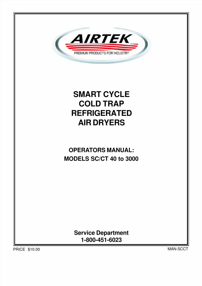
* Locate TAGGED service valves.
* Remove protective cap from valve stem. (see figurebelow)
* Using a refrigeration service wrench or smallcrescent wrench, turn the valve stem counterclock-wise until it stops. Occasionally it may be necessary
to retighten the packing nut (clockwise) if a leak isobserved. The valve will now be fully open.
* Replace cap.
5) Turn dryer on at the control panel by pushing one of themode selection buttons. (SC/CT 220 to 250 should beturned on immediately after TAGGED valves areopened.) If storage conditions were adverse, therefrigerant compressor may make a loud metallichammering noise. If this happens, turn the dryer off atthe control panel, wait half a minute and turn it onagain. repeat this until the refrigerant compressorruns smoothly. The digital dew point display shouldstart dropping to 35ºF.
6) With the dryer turned ON from the control panel andcycling several times, you may now introduce com-pressed air to the dryer. Open the inlet and outletisolation valves. Close the bypass valve.
7) Check automatic drain for proper operation. Drainshould open at regular intervals based on the draincontrol settings or water level. Clean Y-strainer afterthe first 8 hours of operation. (If unit has float, demanddrains there are no Y-strainers.)
8) Restart dryer using this procedure after maintenance,power failure or after prolonged shutdown periods.
CAUTION: Failure to follow the above steps in the ordershown MAY result in damage to equipment NOT coveredunder warranty.
Operating Instructions:
Always:* Turn dryer ON and OFF with control panel button.
Keep power to unit during off cycles.* Start dryer and allow it to cycle several times prior
to allowing air flow through the dryer.* Clean condenser when dirty.* Keep ambient temperature under 100º F.* Keep inlet temperature under 100º F.
* Keep inlet pressure within design limits.* Check and clean Y-strainer periodically. (if appli-
cable)
Never:
* Turn off main power disconnect except whenservicing.
* Allow air to flow through the dryer when it is notrunning.
* Cycle dryer with air compressor.

7/21/2019 Airtek Dryer SC & CT40-3000 Manual
http://slidepdf.com/reader/full/airtek-dryer-sc-ct40-3000-manual 10/41
Airtek 4087 Walden Avenue, Lancaster, NY 14086 TEL: (716) 685-4040 FAX: (716) 685-1010 E-MAIL: [email protected] WEB SITE: www.airtek.com
1
5a. START UP FOR MODELS SC/CT 330 and UP.
NOTE: Please read and understand the entire operation andmaintenance manual prior to starting the dryer. This is a briefstart up procedure for those familiar with dryer operation.
CAUTION: There should be no air flow through the dryerbefore or during start up. It is recommended that the dryer beinstalled with bypass piping to better service the unit.
DRYER START UP PROCEDURE:
1) Make main electrical connection to dryer and applypower. Refer to dryer name plate or manual to determinecorrect voltage. Leave power on unit for 8 hours beforeproceeding.
2) On water cooled units make sure there is proper waterpressure and temperature supplied to the water con-denser. (Min 25 psi and max 85º F water temperature)
3) Remove front cover, if necessary, to expose refrigerationservice valves.
4) Dryers are shipped with TAGGED refrigeration service
valves closed. TAGGED service valves must not beopened until main power is permanently applied.However, ONLY TAGGED service valves must be openedprior to start up.
* LocateTAGGED service valves.
* Remove protective cap from valve stem. (see figurebelow)
* Using a refrigeration service wrench or small crescentwrench, turn the valve stem counterclockwise until itstops. Occasionally it may be necessary to retightenthe packing nut (clockwise) if a leak is observed. Thevalve will now be fully open.
* Replace cap.
* In case of refrigeration ball valves, you must turn 90degrees to open as stated on valve. (See figure below).
5) On models SC/CT 1500 and up, locate the compressorservice toggle switch. This service switch must beturned on immediately after valves are opened.
* On Models SC/CT 1500 and up, the refrigerationcompressor may run briefly and then stop. Thisprocess is called pump down. If storage conditionswere adverse, the compressor may make a loudmetallic hammering noise. If this happens, turn theservice switch off and wait half a minute, then back on.
Repeat this step until the compressor runs smoothly,then stops. Leave the service switch in the ONposition.
6) The dryer is now ready to run. Turn the dryer on at thecontrol panel (load/No Load Mode).
The digital display should start dropping to 35ºF.
7) With the dryer turned ON from the control panel andcycling several times, you may now introduce com-pressed air to the dryer. Open the inlet and outletISOLATION VALVES. Close the BYPASS VALVE.
8) Check automatic drain for proper operation. Drainshould open at regular intervals based on the draincontrol settings. Clean Y-strainer after the first 8 hoursof operation.
9) Restart dryer using this procedure after maintenance,power failure or after prolonged shutdown periods.
CAUTION: Failure to follow the above steps in the order shownMAY result in damage to equipment NOT covered underwarranty.
Operating Instructions:
Always:
* Turn dryer ON and OFF with control panel button. Keeppower to unit during off cycles.
* Start dryer and allow it to cycle several times prior toallowing air flow through the dryer.
* Clean condenser when dirty.
* Keep ambient temperature under 100º F.
* Keep inlet temperature under 100º F.
* Keep inlet pressure within design limits.
* Check and clean Y-strainer periodically. (if applicable)
Never:* Turn off main power disconnect except when servicing.
* Allow air to flow through the dryer when it is not running
* Cycle dryer with air compressor.

7/21/2019 Airtek Dryer SC & CT40-3000 Manual
http://slidepdf.com/reader/full/airtek-dryer-sc-ct40-3000-manual 11/41
Airtek 4087 Walden Avenue, Lancaster, NY 14086 TEL: (716) 685-4040 FAX: (716) 685-1010 E-MAIL: [email protected] WEB SITE: www.airtek.com
11
6. ROUTINE MAINTENANCE AND SERVICE
Air Cooled Condenser
Very little routine care is necessary for the Airtek Dryer. Themost important step for an air cooled dryer is to keep the aircooled condenser clean. The air is being taken in acrossthe condenser. Dirt from the ambient air will accumulate onthe finned tubes of the condenser coil. As the dirt willaccumulate on the rear of the condenser, blowing from theinside out is most effective. In dusty areas the simpleinexpensive installation of a furnace filter will stop themajority of dirt entering the dryer’s condenser. This shouldbe changed when visibly dirty. If the condenser doesbecome dirty, an abnormally high refrigeration dischargepressure will occur. The unit may shut down on high dewpoint or high pressure. This will greatly reduce the life ofthe refrigeration compressor and could lead to a voiding ofthe warranty.
Separator/Coalescer Drains
Drains should be checked regularly. Failure of an auto-matic drain can result in extreme amounts of water and
debris in your air system.7. FOR THE REFRIGERATION SERVICE
TECHNICIANAirtek recommends that only qualified and experiencedrefrigeration mechanics do repair work on these units.This section is a list of hints and instructions for the skilledserviceman and relating specifically to the Airtek SmartCycle and Cold Trap refrigeration systems.
Recharging Dryer – Refrigerant, Oil and Dryers
Refer to the dryer information tag on the front of the unit forthe approximate charge needed for each unit. The relativelylarge charge is needed because of the flooded-shellevaporators. Use the following to assess the adequacy of
the charge when unsure:
* Because of the widely fluctuating pressures occurringwhen the Smart Cycle or Cold Trap system unloads, itis impractical to use pressures or sightglass indica-tions to determine correct charge. Gross underchargeresults in a hot suction line and overheated compres-sor. Gross overcharge is indicated if the head andsuction pressure rises greatly when the unit is loaded.Remember to clean the condenser before deciding onthe charge.
* The sightglass should stay filled most of the timewhen the dryer has its customary air load. It is normal
for the glass to break up when the condenser fanstarts if the load is light or when the unit unloads. Itmay take time to refill when it reloads. Don’t charge toclear the glass with no load; that will be too much.
* All units have a charging fitting on the evaporator shell.The unit must be charged through this fitting and/or theliquid line service valve. The best way is to dump liquidinto both ports with the dryer off, then start up andcontinue feeding a full stream of liquid into the evapo-rator until charged.
Do not charge vapor. You want the charge installed as fastas possible so the oil will be returned.
Additional oil is added at the factory to compensate for themigration with the freon. If a compressor is replaced,remove the drain plug from the evaporator shell to drain anyexcess oil trapped. If that isn’t possible, it may be neces-sary to remove oil from the system after start-up. Excess oilis indicated by noisy and vibrating compressor operation. Ifa replacement evaporator is installed, oil should be added.Prolonged operation with insufficient charge or a bad TXV
may cause oil to be trapped in the evaporator. If thecompressor is still good, this oil will return within a fewminutes of operation with the correct conditions. For R-22applications use 150w refrigeration mineral oil, For R-134Aand R-404A, applications use synthetic refrigeration oil.
Replace both suction and liquid filter-dryers togetherwhenever the system has been exposed to air or water,unless it’s brand new or you know how much air has gonethrough it. Solids will be caught in the suction drier even ifthe system is dry.
NOTE: Magnum models do not have enough receivercapacity to hold the whole charge. A complaint of pressuretripping only on start-up is usually due to air through the
dryer when it is shut down or low cooling pressure ratherthan overcharge. This causes refrigerant to migratebackwards from the evaporator and overfill the high side ofthe system.
Evaporator Leaks
If there is a leak between the tube and shell side of theevaporator, the usual symptom is high head pressure,because the air pressure is higher than the refrigerantpressure.
To determine this, bypass air flow, stop dryer, and observehead pressure after it stabilizes. 20 minutes is sufficient. Ifthe pressure is much higher than that corresponding to theambient temperature, there is air in the system. Purge air
at compressor discharge or receiver inlet to verify.
Gross leak-checking of the evaporator is done at theseparator drain with air pressure off and at least an hourwait. If a leak is verified, it can often be fixed by removingthe bonnets, locating the leak with bubble soap and re-rolling the leaky tubes. Split evaporator tubes can beplugged with special tapered brass plugs.
WARNING: If the refrigerant has been seriously contami-nated with water, you probably won’t be able to dry it withdryers and certainly not vacuum. Best to do solventcleanup on the evaporator and suction accumulator orreplace the evaporator. A flooded shell holds a lot of waterand is difficult to clean effectively.
Refrigerant Control ValvesExpansion valves: The superheat (+15º F) that the valvecontrols is created in the control evaporator or suction lineheat exchanger. There is liquid or zero superheat at themain evaporator outlet to facilitate oil return and keep theshell flooded. If there is superheat at the main evaporatoroutlet or if the suction line to the compressor is warm to thehand, 1) check the charge. If the sightglass is full, 2) theTXV may be defective or the liquid line is blocked. The TXVsuperheat adjustment is not critical.

7/21/2019 Airtek Dryer SC & CT40-3000 Manual
http://slidepdf.com/reader/full/airtek-dryer-sc-ct40-3000-manual 12/41
Airtek 4087 Walden Avenue, Lancaster, NY 14086 TEL: (716) 685-4040 FAX: (716) 685-1010 E-MAIL: [email protected] WEB SITE: www.airtek.com
1
Airtek uses standard type valves that can be found inwholesale houses anywhere. When replacing or repairingthem, remember these points:
* Don’t use any TCLE Alco valves. TCLE valves are tooslow.
* Use cross-ambient “C” or liquid “L” charges. Do notuse any pressure limiting or all-purpose “W” charges.
* We recommend that you increase the superheatsetting of the new valve about 5º F from the factorysetting. Turning the stem 2 turns in is about right.
* Position the sensing bulb of the new valve just wherethe old one was. It is crucial that the suction line beclean and the bulb well insulated.
Solenoid Valves: The suction solenoid valve rarely causesany trouble because the pressure difference across it isnever great. Unloader solenoids operate with greaterdifferentials and so are more likely to fail. Airtek usesvalves with a rated life of more than two million operations.When they finally wear out, the usual symptom is failure to
close. The valves can usually be restored by installing adiaphragm repair kit available from Airtek or the valve’slocal distributor.
DrainsThe draining of water from the separator is the most crucialpart of the whole process. A complaint of “There’s morewater in the air now than there was before the dryer wasinstalled” is usually a drain problem.
Airtek has a demand operated drain. Operate the drainmanually, push to test. Check the float switch, board orsolenoid valve if not.
Electronic Controls
A dew point temperature controller is used on the SmartCycle Dryers. The controller operates the unloadersolenoid, opening it to stop refrigeration if the sensedtemperature goes below the controller setting, usually 36ºF.The suction solenoid is closed during unloading.
This temperature is sensed by a sensing probe inserted inone of the evaporator tubes. When air passes over theprobe, the air temperature controls the dew point normally.When there is little or no air flow, the controller sees theevaporator temperature, and is able to prevent it from goingbelow freezing.The operation of the dew point controller is really simple.All it does is switch back and forth between opening the
suction line solenoid and closing the unloader and viceversa. A malfunction of the control system can be sus-pected if:
1) The suction pressure won’t fall when the dew point isabove the set point. You can suspect the unloadersolenoid isn’t closing due to a bad diaphragm.
2) The suction pressure won’t rise when the dew pointgoes below the set point and the controller switches, inload/unload mode. If the pressure falls rapidly whenthe controller switches to “power saver” mode theunloader solenoid isn’t opening. If controller switch
doesn’t seem to do anything it has to be the controlleror wiring.
3) Suction pressure is very low even when controllerreads over the set point or unit appears to be pumpeddown and stopped when it shouldn’t be. One or bothsolenoids isn’t opening when it should.
4) Water freezes in the evaporator causing air pressure
drop (dew point set 34 or higher). This can be partialfailure of unloader solenoid to open, indicated by morethan 60 PSI difference between compressor suctionand discharge.
5) There is erratic or out-of-range indication of dew point.This is controller or sensor trouble. Consult factory fordetails.
6) Dryer won’t restart after you stopped it for a test. Thisis normal if you stopped when it was unloaded (load-unload mode) or shut down (start-stop mode). It willrestart when the dew point temperature comes abovethe controller setting.
NOTE: For a complete troubleshooting guide, see pages30-35.
Remember that the easiest way to distinguish betweencontrol and solenoid malfunction is to hold a steel object,like a pocket screw driver, over the top of the valve’senclosing tube that sticks out from the coil and feel formagnification. The magnification means the valve isenergized. If you don’t feel it, remember to look at the coilbefore suspecting the controller.
The two displays marked AMBIENT or WATER and AIR INindicate those temperatures and control only the respectivealarm lights (see ADJUSTMENTS). It is an alarm only andwill not shut your unit down.
Factory Assistance
Please do not hesitate to call the Airtek factory for technicalinformation and assistance. We have skilled troubleshoot-ing and engineering personnel who are thoroughly familiarwith the equipment. A short call may save a long trouble-shooting experience. 1-800-451-6023.
Instructions for Ordering Parts
All parts orders should be placed with your Airtek Dealer.Should you not know the dealer in your area, contact Airtekat (800) 451-6023.
When ordering parts, specify dryer model and serialnumbers to insure receiving proper parts (see nameplate
on unit).

7/21/2019 Airtek Dryer SC & CT40-3000 Manual
http://slidepdf.com/reader/full/airtek-dryer-sc-ct40-3000-manual 13/41
Airtek 4087 Walden Avenue, Lancaster, NY 14086 TEL: (716) 685-4040 FAX: (716) 685-1010 E-MAIL: [email protected] WEB SITE: www.airtek.com
13
8. MISCELLANEOUS DRYER DATA
Capacity Correction Factory
All dryer ratings shown are at 100ºF inlet temperature,100ºF ambient temperature, 100 PSIG inlet pressure. Tocorrect for different conditions, use Table A, B, C, and D.
Correction Formula:
New Capacity SCFM = (Cat. Rating SCFM) x (A) x (B) x (C) x(D)
Example: What is the new rating for a Model 3000 at:
(A) Operating PSI of 100 PSIG(B) Ambient Temperature of 90ºF.(C) Inlet air temperature of 110ºF. and(D) Dew point of 35 - 39ºF
Answer:
(SCFM) = 3000 x (1) x (1.05) x (.83) x 1 = 2614.5 SCFM
C Temp. ºF 80 90 100 110 120
Factor 1.5 1.22 1 .83 .69
Inlet Air Temperature Correction
PSI 50 75 100 125 150
Factor 0.8 0.9 1 1.02 1.05
D
B
A
Temp. ºF 90 100 110 --- ----
Factor 1.05 1 0.9 --- ---
Dew Point 35ºF - 39ºF 42ºF - 45ºF 50ºF
Factor 1 1.10 1.25
Ambient Air Temperature Correction
Inlet Air Pressure Correction
Dew Point Correction Factors
7/21/2019 Airtek Dryer SC & CT40-3000 Manual
http://slidepdf.com/reader/full/airtek-dryer-sc-ct40-3000-manual 14/41
Airtek 4087 Walden Avenue, Lancaster, NY 14086 TEL: (716) 685-4040 FAX: (716) 685-1010 E-MAIL: [email protected] WEB SITE: www.airtek.com
1
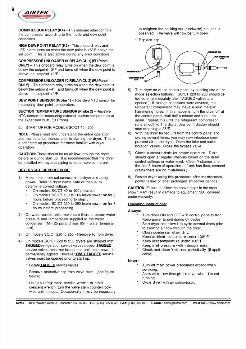
9. Dryer Information Charts
* Approximate running amps 460 volt / 3 ph = 2.0 amps. x HP* Approximate running amps 230 volt / 3 ph = 4.0 amps x HP. For exact RL amps check name plate* Approximate locked rotor amps = 4 to 6 times running amps.
* Water Cooled Units - Max Water PSI = 105 PSIMin Water PSI = 25 PSIMax Water Temperature = 85ºF
NOTE: (1) “M/C” amps is minimum circuit ampacity value developed by UL, this value has a calculated safety value andmay be used for wire sizing.
* Pressures referenced in this section refer to units using R-22. For other refrigerants, please refer to service
tag for specifications.
NOTE: If you own a watercooled unit, the second last character in your model number will be a “W” (ie: SC/CT1000-W4)
SC/CT 40 0.33 7.1 115/1 6.8 20 20 3750 275 3 oz.SC/CT 60 0.5 9.5 115/1 13.5 20 20 7500 350 3 oz.SC/CT 80 0.5 9.9 115/1 13.5 20 20 7500 350 3 oz.SC/CT 100 0.75 13.8 115/1 19.5 30 30 11250 800 3 oz.SC/CT 130 0.75 14.0 115/1 19.6 30 30 11250 800 3 oz.SC/CT 165 0.75 14.3 115/1 19.6 30 30 11250 800 3 oz.SC/CT 220-A2 1 7.3 230/1 8.7 20 15 15000 1050 3 oz.SC/CT 220-A4 1.5 3.8 460/3 6 15 15 22500 1125 3 oz.SC/CT 250-A2 1.5 10.36 230/1 15.9 20 15 22500 1125 3 oz.SC/CT 250-A4 1.5 3.9 460/3 6 20 15 22500 1125 3 oz.SC/CT 330-A2 1.5 10.36 230/1 15.9 20 20 22500 1125 8 oz.SC/CT 330-A4 1.5 3.3 460/3 6 15 15 22500 1125 8 oz.SC/CT 400-A2 2 13.4 230/1 19.1 30 30 30000 2000 15 oz.SC/CT 400-A3 2 8.48 230/3 13.2 20 20 300000 2000 15 oz.SC/CT 400-A4 2 4.24 460/3 6.8 15 15 300000 2000 15 oz.SC/CT 500-A3 3 13.4 230/3 23.7 30 30 45000 2300 15 oz.SC/CT 500-A4 3 6.7 460/3 11.6 20 20 45000 2300 15 oz.SC/CT 650-A3 3 13.4 230/3 23.7 30 30 45000 2300 15 oz.SC/CT 650-A4 3 6.7 460/3 11.6 20 20 45000 2300 15 oz.SC/CT 800-A3 4 17.9 230/3 25.9 30 30 60000 4200 18 oz.SC/CT 800-A4 4 10.6 460/3 13.2 30 30 60000 4200 18 oz.SC/CT 1000-A4 5 9.6 460/3 14.4 20 20 75000 5000 24 oz.SC/CT 1200-A4 5 9.8 460/3 14.4 20 20 75000 5000 24 oz.SC/CT 1500-A4 7.5 16.1 460/3 20.1 30 30 112500 5600 30 oz.SC/CT 2000-A4 10 19.1 460/3 20.1 30 40 150000 5850 45 oz.
SC/CT 2500-A4 15 23.9 460/3 38.4 40 60 225000 12900 45 oz.SC/CT 3000-A4 15 24.1 460/3 38.4 40 60 225000 12900 69 oz.
(1) Max HeatRef. Volt “MC” Max Circuit Reject Fan Additional
Model No. HP FLA PH Amps Fuse Breaker BTU/HR CFM Oil Change
7/21/2019 Airtek Dryer SC & CT40-3000 Manual
http://slidepdf.com/reader/full/airtek-dryer-sc-ct40-3000-manual 15/41
Airtek 4087 Walden Avenue, Lancaster, NY 14086 TEL: (716) 685-4040 FAX: (716) 685-1010 E-MAIL: [email protected] WEB SITE: www.airtek.com
15
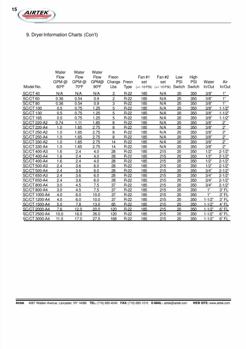
9. Dryer Information Charts (Con’t)
SC/CT 40 N/A N/A N/A 2 R-22 185 N/A 20 350 3/8” 1”
SC/CT 60 0.36 0.54 0.9 2 R-22 185 N/A 20 350 3/8” 1”SC/CT 80 0.36 0.54 0.9 3 R-22 185 N/A 20 350 3/8” 1”SC/CT 100 0.5 0.75 1.25 5 R-22 185 N/A 20 350 3/8” 1-1/2”SC/CT 130 0.5 0.75 1.25 5 R-22 185 N/A 20 350 3/8” 1-1/2”SC/CT 165 0.5 0.75 1.25 5 R-22 185 N/A 20 350 3/8” 1-1/2”
SC/CT 220-A2 0.74 1.11 1.85 8 R-22 185 N/A 20 350 3/8” 2”SC/CT 220-A4 1.0 1.65 2.75 8 R-22 185 N/A 20 350 3/8” 2”SC/CT 250-A2 1.0 1.65 2.75 8 R-22 185 N/A 20 350 3/8” 2”SC/CT 250-A4 1.0 1.65 2.75 8 R-22 185 N/A 20 350 3/8” 2”SC/CT 330-A2 1.0 1.65 2.75 14 R-22 185 N/A 20 350 3/8” 2”SC/CT 330-A4 1.0 1.65 2.75 14 R-22 185 N/A 20 350 3/8” 2”SC/CT 400-A3 1.6 2.4 4.0 28 R-22 185 215 20 350 1/2” 2-1/2”SC/CT 400-A4 1.6 2.4 4.0 28 R-22 185 215 20 350 1/2” 2-1/2”SC/CT 400-A4 1.6 2.4 4.0 28 R-22 185 215 20 350 1/2” 2-1/2”SC/CT 500-A3 2.4 3.6 6.0 28 R-22 185 215 20 350 1/2” 2-1/2”SC/CT 500-A4 2.4 3.6 6.0 28 R-22 185 215 20 350 3/4” 2-1/2”SC/CT 650-A3 2.4 3.6 6.0 28 R-22 185 215 20 350 3/4” 2-1/2”SC/CT 650-A4 2.4 3.6 6.0 28 R-22 185 215 20 350 3/4” 2-1/2”SC/CT 800-A4 3.0 4.5 7.5 37 R-22 185 215 20 350 3/4” 2-1/2”SC/CT 800-A4 3.0 4.5 7.5 37 R-22 185 215 20 350 1” 3” FLSC/CT 1000-A4 4.0 6.0 10.0 37 R-22 185 215 20 350 1” 3” FLSC/CT 1200-A4 4.0 6.0 10.0 37 R-22 185 215 20 350 1-1/2” 3” FLSC/CT 1500-A4 5.0 7.8 13.0 65 R-22 185 215 20 350 1-1/2” 4” FLSC/CT 2000-A4 7.6 12.0 20.0 120 R-22 185 215 20 350 1-1/2” 6” FLSC/CT 2500-A4 10.0 16.0 26.0 120 R-22 185 215 20 350 1-1/2” 6” FLSC/CT 3000-A4 11.0 17.0 27.5 168 R-22 185 215 20 350 1-1/2” 6” FL
Water Water WaterFlow Flow Flow Freon Fan #1 Fan #2 Low High
GPM @ GPM @ GPM@ Change Freon set set PSI PSI Water AirModel No. 60ºF 70ºF 90ºF Lbs Type (+/- 10 PSI) (+/- 10 PSI) Switch Switch In/Out In/Out

7/21/2019 Airtek Dryer SC & CT40-3000 Manual
http://slidepdf.com/reader/full/airtek-dryer-sc-ct40-3000-manual 16/41
Airtek 4087 Walden Avenue, Lancaster, NY 14086 TEL: (716) 685-4040 FAX: (716) 685-1010 E-MAIL: [email protected] WEB SITE: www.airtek.com
1

7/21/2019 Airtek Dryer SC & CT40-3000 Manual
http://slidepdf.com/reader/full/airtek-dryer-sc-ct40-3000-manual 17/41
Airtek 4087 Walden Avenue, Lancaster, NY 14086 TEL: (716) 685-4040 FAX: (716) 685-1010 E-MAIL: [email protected] WEB SITE: www.airtek.com
17
7/21/2019 Airtek Dryer SC & CT40-3000 Manual
http://slidepdf.com/reader/full/airtek-dryer-sc-ct40-3000-manual 18/41
Airtek 4087 Walden Avenue, Lancaster, NY 14086 TEL: (716) 685-4040 FAX: (716) 685-1010 E-MAIL: [email protected] WEB SITE: www.airtek.com
1

7/21/2019 Airtek Dryer SC & CT40-3000 Manual
http://slidepdf.com/reader/full/airtek-dryer-sc-ct40-3000-manual 19/41
Airtek 4087 Walden Avenue, Lancaster, NY 14086 TEL: (716) 685-4040 FAX: (716) 685-1010 E-MAIL: [email protected] WEB SITE: www.airtek.com
19

7/21/2019 Airtek Dryer SC & CT40-3000 Manual
http://slidepdf.com/reader/full/airtek-dryer-sc-ct40-3000-manual 20/41
Airtek 4087 Walden Avenue, Lancaster, NY 14086 TEL: (716) 685-4040 FAX: (716) 685-1010 E-MAIL: [email protected] WEB SITE: www.airtek.com
2

7/21/2019 Airtek Dryer SC & CT40-3000 Manual
http://slidepdf.com/reader/full/airtek-dryer-sc-ct40-3000-manual 21/41
Airtek 4087 Walden Avenue, Lancaster, NY 14086 TEL: (716) 685-4040 FAX: (716) 685-1010 E-MAIL: [email protected] WEB SITE: www.airtek.com
21

7/21/2019 Airtek Dryer SC & CT40-3000 Manual
http://slidepdf.com/reader/full/airtek-dryer-sc-ct40-3000-manual 22/41
Airtek 4087 Walden Avenue, Lancaster, NY 14086 TEL: (716) 685-4040 FAX: (716) 685-1010 E-MAIL: [email protected] WEB SITE: www.airtek.com
2

7/21/2019 Airtek Dryer SC & CT40-3000 Manual
http://slidepdf.com/reader/full/airtek-dryer-sc-ct40-3000-manual 23/41
Airtek 4087 Walden Avenue, Lancaster, NY 14086 TEL: (716) 685-4040 FAX: (716) 685-1010 E-MAIL: [email protected] WEB SITE: www.airtek.com
23
7/21/2019 Airtek Dryer SC & CT40-3000 Manual
http://slidepdf.com/reader/full/airtek-dryer-sc-ct40-3000-manual 24/41
Airtek 4087 Walden Avenue, Lancaster, NY 14086 TEL: (716) 685-4040 FAX: (716) 685-1010 E-MAIL: [email protected] WEB SITE: www.airtek.com
2
7/21/2019 Airtek Dryer SC & CT40-3000 Manual
http://slidepdf.com/reader/full/airtek-dryer-sc-ct40-3000-manual 25/41
Airtek 4087 Walden Avenue, Lancaster, NY 14086 TEL: (716) 685-4040 FAX: (716) 685-1010 E-MAIL: [email protected] WEB SITE: www.airtek.com
25
7/21/2019 Airtek Dryer SC & CT40-3000 Manual
http://slidepdf.com/reader/full/airtek-dryer-sc-ct40-3000-manual 26/41
Airtek 4087 Walden Avenue, Lancaster, NY 14086 TEL: (716) 685-4040 FAX: (716) 685-1010 E-MAIL: [email protected] WEB SITE: www.airtek.com
2

7/21/2019 Airtek Dryer SC & CT40-3000 Manual
http://slidepdf.com/reader/full/airtek-dryer-sc-ct40-3000-manual 27/41
Airtek 4087 Walden Avenue, Lancaster, NY 14086 TEL: (716) 685-4040 FAX: (716) 685-1010 E-MAIL: [email protected] WEB SITE: www.airtek.com
27

7/21/2019 Airtek Dryer SC & CT40-3000 Manual
http://slidepdf.com/reader/full/airtek-dryer-sc-ct40-3000-manual 28/41
Airtek 4087 Walden Avenue, Lancaster, NY 14086 TEL: (716) 685-4040 FAX: (716) 685-1010 E-MAIL: [email protected] WEB SITE: www.airtek.com
2

7/21/2019 Airtek Dryer SC & CT40-3000 Manual
http://slidepdf.com/reader/full/airtek-dryer-sc-ct40-3000-manual 29/41
Airtek 4087 Walden Avenue, Lancaster, NY 14086 TEL: (716) 685-4040 FAX: (716) 685-1010 E-MAIL: [email protected] WEB SITE: www.airtek.com
29

7/21/2019 Airtek Dryer SC & CT40-3000 Manual
http://slidepdf.com/reader/full/airtek-dryer-sc-ct40-3000-manual 30/41
Airtek 4087 Walden Avenue, Lancaster, NY 14086 TEL: (716) 685-4040 FAX: (716) 685-1010 E-MAIL: [email protected] WEB SITE: www.airtek.com
3
Caution: The following procedures are developed for thequalified Electrician or Refrigeration Technician. Only qualifiedpersonnel should attempt these procedures.
Caution: When checking or repairing any unit, exercise allsafety and caution rules. Disconnect power and depressurizeunit when necessary.
* Pressures referenced in this section refer to units using
R-22. For other refrigerants, please refer to service tagfor specifications.
Refrigerated Dryer Diagnostic Code
Diagnostic code “E1”Shutdown on Open Dew Point Circuit
The dew point sensing circuit is devised of three parts.The dew point probe, cable and digital control board. Thecombination of these parts measures the air temperatureleaving the evaporator.
There are two connections in the dew point sensingcircuit, one between the probe (inserted in the right side of the
evaporator) and cable, and one between the cable and thecontrol board. If either of these two connections is broken adiagnostic code of “E1” will appear on the control boarddisplay, after 1 0 seconds the dryer will shut down. The dryerwill not be able to be restarted until the problem is corrected.
The easiest way to correct this is to check all connectionsto make sure they are secure. If they are and you are stillexperiencing the problem, there is a possibility there is aninternal break in the sensing circuit without the circuit shortingout.
To locate the break, here is the sequence of steps to be taken:
1) Locate the connection between the probe and the cable
and disconnect it. Make sure it is secured above thecompression fitting. The connection hanging low couldattract condensation from the probe compression fitting.This water could get into the connection causing an opencircuit.
2) Looking at the female end of the cable connection notethe five terminal points arranged in a clock like fashion, 9,11, 12, 1 and 3 o’clock.
3) Taking a piece of insulated wire stripped on both ends,place the ends into the 9 and 3 o’clock positions. If thedigital display then changes to “E2” the break is in theprobe.
4) If the display remains at “E1” disconnect power from the
unit and disconnect the cable (probe 1) from the maindew point control board.
5) Looking at the male connection (labeled as Probe 1)terminals on the control board, number them 1, 2, 3,respectively from left to right facing the back of the boardwith the board in an upright position the way it is mountedin the dryer.
6) Take a jumper wire and attach the ends to terminal 1 and2. Reapply power. If the display changes to “E2” the breakis in the cable. Replace the cable. If the display remains“E1” the break is in the board. Replace the board.
Diagnostic code “E2”Shutdown on Shorted Dew Point Circuit
The dew point sensing circuit is devised of threeparts, The dew point probe, cable and digital control board.The combination of these parts measures the air tempera-ture leaving the evaporator.
If a short should occur somewhere in the dewpoint sensing circuit, a diagnostic code of “E2” will appearon the control board. After 1 a seconds of this condition thedryer will shut down. The dryer will not be able to berestarted until the problem is corrected.
To determine which component is at fault, first findthe two connections in the sensing circuit, one between thedew point probe and cable, and one between the cable andthe digital control board.
Then follow these simple steps.
1) Locate the connection between the probe and cableand disconnect it. Make sure it is secured above the
compression fitting. The connection hanging low couldattract condensation from the probe compressionfitting. This water could get into the connection causingan open circuit.
2) Should the display on the digital control board changefrom a “E2” to a “E1”, the short is in the dew pointprobe. Replace it.
3) If the display continues to show a “E2” disconnectpower to the unit and locate the connection betweenthe cable and the digital control board, and disconnectit.
4) Reapply power. If the display then changes to an “E1”the short is in the cable. Replace the cable.
5) If the display still shows a “E2” the short is in thesuction line temperature probe (E3 Probe) or the digitalcontrol board. The process to determine to disconnectpower connection labeled “Probe 2”
1) Disconnect the cable. Reapply power. If thedisplay changes from “E2” to a number, theshort is in the suction temperature probe.Replace the probe. If the “E2” remains theshort is in the control board. Replace thecontrol board.
Diagnostic code “E3”
Shutdown on High Super HeatSuper heat is defined by the differential temperature
between the thermal expansion valve bulb and the actualdew point. The standard superheat setting fluctuatesbetween 10ºF. and 25ºF.
If the temperature at the thermal expansion valvesensing probe is 40ºF higher than the actual dew pointreadout for 40 minutes, the display will read “E3” andautomatically shut down. This shutdown eliminates acompressor seizure. The dryer can be reset by pressing

7/21/2019 Airtek Dryer SC & CT40-3000 Manual
http://slidepdf.com/reader/full/airtek-dryer-sc-ct40-3000-manual 31/41
Airtek 4087 Walden Avenue, Lancaster, NY 14086 TEL: (716) 685-4040 FAX: (716) 685-1010 E-MAIL: [email protected] WEB SITE: www.airtek.com
31
the mode selection button to turn the unit off then pressingit again to turn it on. If the condition is not corrected the unitwill shut down again in 40 minutes.
Reset the unit once more. Wait 5 minutes and checkyour superheat. To check the superheat press the hiddenbutton located between the two mode selection buttons. Ifthe temperature is not within range, check the following
probable causes:A) Low Freon Charge
Examine sightglass, if you can see a level or aflurry of bubbles for a long period of time you maybe low on freon. It is common to see an occa-sional bubble at times. It is also common to see aflurry of bubbles when the dryer loads andunloads.
Another way to check freon level is with an inferredheat gun to the liquid line receiver if it is not a 1/3full this may be an indication you are low on freon.
If you are low on freon the unit needs to be leakchecked and charged.
If you are still shutting down on “E3” and your super heattemperature is within range the probable causes are:
B) Poor Contact of Super Heat Sensing ProbeLocate the superheat-sensing probe, which will belocated next to the thermal expansion valvesensing bulb. If for some reason it is not tightenedsecurely to the copper line it will sense a higherambient temperature. This will provide a falsereading to the control board of high super heat,and in turn the unit will shut down “E3”. If the “E3”probe is loose, tighten copper strap securely forbest results.
C) Defective Super Heat Probe If the “E3” probe is tightened securely to thecopper line and your super heat is within range(10º - 25ºF), and your dryer is still shutting down on“E3”, your probe is defective. To check this,disconnect power from the unit. Locate the probeconnection (labeled probe 2) and disconnect itfrom the board, if it runs fine after this, replaceprobe. Reapply power. If it still shuts down on “E3”after 40 minutes, replace the control board.
D) Expansion Valve Stuck Closed
Test by applying heat (hair dryer) to TXV sensingbulb located just after the flood level control forabout 30-45 seconds. This should cause the unit
to flood back and lower the super heat. To checkthis, take a temperature reading on the suctionaccumulator, it should be extremely cold, if it is not,your expansion valve is stuck closed. Your suctionaccumulator normally shows a level based ontemperature of being 1/3 to 1/2 full.
Diagnostic code “E4”Shutdown on Freeze Protection
Freezing is defined as the point at which the actualdew point falls to 20ºF or lower. If this condition occurs and
lasts for ten minutes, an “E4” will display and the dryer willshut down. This will prevent the unit from freezing. Mostimportantly it will save the evaporator from developing aleak due to expansion of moisture which may be presentwithin the evaporator tubing.
The probable cause of this problem is the unloadervalve failing to open in some matter. To further diagnose the
cause of this failure and to check operation, turn the unit offthen on again after 15 seconds using the Load/Unloadmode. This will clear the diagnostic code and cause theunit to operate again. When the dew point falls below thedew point set point the Power Saver Active light shouldcome on and the following items should be checked:
1) You need to first check the coil of the unloadervalve to ensure that it is functioning. The easiestway to verify if the coil is energized is to take ascrewdriver and touch it to the screw or post on thetop of the coil. If the coil is energized there will be amagnetic field pulling the metal to the screw orpost. If the Power Saver Active light is on and thereis no magnetic pull, the coil is not functioning.
2) If you have determined the coil is not functioningthere are two things you must check, Test the coilelectrically for continuity to ensure it is not shorted.If it is shorted replace the coil. If the coil is notshorted you need to check the K3 relay on the backof the control board marked “Unloader”, terminals9 and 10. There should be a 120V output from thisrelay. If there is not replace the board.
3) If the coil is functioning and the dew point contin-ues to fall, the unloader solenoid is defective. Theinternals or the whole valve should be replaced.
Remember all of this must be checked while the unit is
operative and in the unloaded state. The way this isdetermined is by the Power Saver Active light beingilluminated.
Diagnostic code “E5”High Dew Point Shutdown
If the actual dew point on the digital control boardreads 40ºF higher than the dew point set point for 10minutes, the dryer will shut down and a diagnostic code of“E5”.
The probable causes for this condition is the unloadersolenoid sticking open, or a weak or defective compressor.
The dryer can be reset by pressing the mode selectionbutton to turn the unit off, and then pressing it again will turnthe unit back on. If the dew point does not fall check thefollowing:
A) Unloader valve stuck open.1) You first need to determine if the unloader valve is
functioning properly. When the dryer is refrigeratingand the Power Saver Active light is off, the unloadervalve should be de-energized and closed. It isunlikely that the coil is shorted closed but notimpossible. You can check the solenoid electri-cally to see if it is getting an electric signal. Another

7/21/2019 Airtek Dryer SC & CT40-3000 Manual
http://slidepdf.com/reader/full/airtek-dryer-sc-ct40-3000-manual 32/41
Airtek 4087 Walden Avenue, Lancaster, NY 14086 TEL: (716) 685-4040 FAX: (716) 685-1010 E-MAIL: [email protected] WEB SITE: www.airtek.com
3
way to see if the coil is energized is to take ascrewdriver or something metal and touch it to thescrew or post on the top of the coil. When the coilis energized there is a magnetic field producedwhich will pull the metal object to the screw post. Ifit is, the coil may be shorted closed, causing thedigital control board to give a constant electricsignal from the K3 relay affixed to the back of theboard. If this is the case replace the control board,and the coil.
2) If you have determined that the valve is not gettingenergized electrically, then the valve may havemalfunctioned mechanically. Determining this isrelatively easy. When the dryer is refrigerating andthe Power Saver Active light is off we know that theunloader solenoid should be closed. If it has failedmechanically there will be equal temperaturecopper lines in and out of the valve. There isalways hot gas on the incoming side of thesolenoid; therefore it should be hot. If the valve isclosed the copper line on the outgoing side of the
solenoid should be relatively cool. It would besuggested that you check the copper line justbefore it enters the static cooler near the evapora-tor, due to the fact that some heat may transferthrough the metal of the valve and show hot just onthe out going line of the solenoid. This tempera-ture can be checked by infrared temperature gun. Ifthis seems to be the problem the internals of orthe whole valve should be replaced.
If you have determined that the unloader solenoidis fine the other problem component would be thecompressor. Check the following:
B) Compressor will not start, no hum.
1) Service toggle switch is in off position. Turn on.(Models SC/CT1500 and up.)
2) Fuse removed or blown. Replace fuse.3) Overload tripped. Wait 5 to 20 minutes to reset.
Check ambient and inlet air temperatures,operating pressures and airflow rates againstrated capacities listed, to determine cause ofoverload.
4) Loose or improper wiring. Check connectionsagainst schematic. Tighten loose connections.
5) Starter coils open or contact burnt. Replace coilsand/or contact.
C) Compressor will not start, hums, trips overload
protector.1) Loose or improper wiring.2) Low line voltage, 10% less of nameplate rating.
Check line voltage with voltmeter. Correct condi-tion.
3) Start windings open or shorted. Check withohmmeter, referring to motor schematic for correctvalue. Replace motor.
4) Open or unbalanced phase (3 phase units).Check phases for equal voltages (+/-10%). Correctunbalanced or open condition.
5) Relay or contactor not closing. Examine contactsand coils for burning, opens, shorts or sticking.Correct conditions.
6) Compressor internal mechanical failure. Loss ofoil may have locked up the compressor. If abovesteps do not apply, this may be the cause.Replace compressor.
D) Unit short-cycles.1) Motor overload cutting. Check for high headpressure or air overload, high ambient cloggedcondenser.
2) Defective overload protectors. Check currents.Replace if necessary.
3) Low voltage or 3 phase unbalance. Voltage mustbe within 10% on nameplate rating. Correct offspecification conditions.
4) Refrigerant Shortage. Check for leaks. Repair andrecharge.
5) Shortage motor windings. If the dryer begins torun examine the dew point. If it does not fall to the
dew point set point check the following things.
E) Weak Compressor
1) A refrigeration technician would be needed to justify a faulty compressor. If the compressor isrunning and the freon pressures are somewhatequalized from the high side of the system to thelow side the compressor is not pumping. The onlycure for this is a replacement compressor. Again,a refrigeration technician would be needed toperform the repair.
Diagnostic code “E6”Shutdown on Low Suction PSI
* Pressures referenced in this section refer to unitsusing R-22. For other refrigerants, please refer to
service tag for specifications.
If the suction pressure of the refrigeration systemdrops 20 PSI or lower it will break contact through the low-pressure switch. This in turn breaks power to the refriger-ant compressor for protection.
To correct this 1. Bypass the compressed air aroundthe dryer. 2. Based on the size of the unit you will haveeither manual resetting pressure switches, or a resetthrough the control panel by pressing the mode selectionbutton off then on again after 10 seconds. If the conditioncontinues, check the following probable causes:
A) Low Freon - Typically if the unit were low on freonyou would see an “E3” code. However if there wasfor some reason a large loss of freon in short timethis could result in a low-pressure cut out. Thiscondition is usually caused by a large leak due toa damaged refrigerant line.
1) Some ways of determining a leak is tophysically examine the unit for what mayappear as a puddle or spray of oil. Refrigerantcarries the lubricant for the compressor andwould show up where the leak occurred.
7/21/2019 Airtek Dryer SC & CT40-3000 Manual
http://slidepdf.com/reader/full/airtek-dryer-sc-ct40-3000-manual 33/41
Airtek 4087 Walden Avenue, Lancaster, NY 14086 TEL: (716) 685-4040 FAX: (716) 685-1010 E-MAIL: [email protected] WEB SITE: www.airtek.com
33
Another possible determining factor would bethe appearance of the refrigerant sightglass. Itnormally appears clear with a color moistureindicator in the center. If the moisture indicatoris yellow, chances are there is a leak in thesystem. The best way to determine a leak is tocontact a refrigeration service house. Theyhave the technology of a halide torch or
electronic leak detectors.
B) Pressure Switch - If you are low on freon or freonpressure the low-pressure switch will be showingelectrically open. You can check the low-pressureswitch for continuity to see if the switch is in factopen. If it is closed you may have a control boardproblem. There is a possibility the pressure switchmay be faulty giving a false low-pressure indica-tion. Again the best way to determine this is tocontact a refrigeration service house. With theirgauges they can check the system pressure andthe settings of the pressure switch. The low-pressure switch is set to trip at 20 PSI. If you have
an automatic resetting switch it will close again at50 PSI.
C) Unloader Solenoid Failing to Open
1) You need to first check the coil of the unloadervalve to ensure that it is functioning. Theeasiest way to verify if the coil is energized isto take a screwdriver and touch it to the screwor post on the top of the coil. If the coil isenergized there will be a magnetic fieldpulling the metal to the screw or post. If thePower Saver Active light is on and there is nomagnetic pull, the coil is not functioning.
2) If you have determined the coil is not function-
ing there are two things you must check.
- Test the coil electrically for continuity toensure it is not shorted. If it is shortedreplace the coil.
- If the coil is not shorted you need to checkthe K3 relay marked “Unloader”, termi-nals 9 and 10. There should be a 120Voutput from this relay. If there is notreplace the board.
3) If the coil is functioning and the dew pointcontinues to fall, or the unit shuts downdisplaying an “E6”, the unloader solenoid isdefective. The internals or the whole valve
should be replaced.
Remember the unloader must be checked while the unit isoperative and in the unloaded state. The way this isdetermined is by the Power Saver Active light beingilluminated.
D) Refrigerant restriction - If there should be arestriction in the refrigerant system this couldcause a low-pressure situation. The mostcommon points of restriction are:
1) Faulty suction line solenoid - If the suction linesolenoid (SC/CT1500 and up) were defective
.or not functioning electronically, this couldcause a restriction. When the Power SaverActive light is off the suction line solenoidshould be energized and fully open. To verifythis examine the following:
a) You need to first check the coil of theliquid line valve to ensure that it is
functioning. The easiest way to verify if thecoil is energized is to take a screwdriverand touch it to the screw or post on thetop of the coil. If the coil is energized therewill be a magnetic field pulling the metalto the screw or post. If the Power SaverActive light is off and there is no magneticpull; the coil is not functioning.
b) If you have determined the coil is notfunctioning there are two things you mustcheck.
- Test the coil electrically for continuityto ensure it is not shorted. If it is
shorted replace the coil.- If the coil is not shorted you need tocheck the K2 relay marked “Suction”,terminals 7 and 8. There should be a120V output from this relay. If there isnot replace the board.
c) If the coil is functioning and the restrictionseems to remain the valve may be theproblem. The internals or the whole valveshould be replaced. Or the restrictioncould be in the expansion valve. This israre but possible.
Remember all of this must be checked while the unit is
operative and in the refrigerating state. The way this isdetermined is by the Power Saver Active light being off.
2) Service valve. When the dryer is fully opera-tive, all refrigeration service valves with theexception of the service valve on the bottom ofthe evaporator on models SC/ CT330’s andup, should be open. If one should be closed,even partially, this could cause enough of arestriction to cause low-pressure problems.
3) Faulty expansion valve. This is a very raresituation however there is means of testingthis theory. Test by applying heat (hair drier) toTXV sensing bulb located just after the flood
level control for about 30-45 seconds. Thisshould cause the unit to flood back and lowerthe super heat. To check this, take a tempera-ture reading on the suction accumulator, itshould be extremely cold, if it is not, yourexpansion valve is stuck closed or is dirty.Check to make sure that the capillary tubefrom the power head to the sensing bulb isnot severed, this could cause the valve toclose. Your suction accumulator normallyshows a level based on temperature of being1/3 to 1/2 full. If it is less you may have arestriction.

7/21/2019 Airtek Dryer SC & CT40-3000 Manual
http://slidepdf.com/reader/full/airtek-dryer-sc-ct40-3000-manual 34/41
Airtek 4087 Walden Avenue, Lancaster, NY 14086 TEL: (716) 685-4040 FAX: (716) 685-1010 E-MAIL: [email protected] WEB SITE: www.airtek.com
3
E) Disconnected or Faulty Jumper Wire (Very rare) -There is a violet jumper wire that runs from theoutgoing current on the low-pressure switch toterminal 18 on the main dew point controller. Thisterminal must see power at all times in order forthe unit to function. If the low-pressure switchopens it severs power to terminal 18 and the unit
shuts down on “E6”, However if the jumper wire isfaulty or disconnected terminal 18 does not seepower and will shut down on a false “E6”. To checkremove power from the unit and check for continu-ity through the jumper wire if there is none inspectand/or replace wire. Reapply power. If the unit stillshows “E6” and the low-pressure switch haschecked good, the problem is in the board.
Diagnostic code “E7”Shutdown on High Head PSI
* Pressures referenced in this section refer to units
using R-22. For other refrigerants, please refer to
service tag for specifications.If the discharge or “head” pressure of the dryer refrigerationunit exceeds 350 psi it breaks contact through the high-pressure switch. This in turn breaks power to the refriger-ant compressor shutting it down for protection.
To correct this, 1. Bypass the compressed air aroundthe dryer. 2. Based on the size of the unit you will haveeither manually resetting pressure switches, or a resetthrough the control panel by pressing the mode selectionbutton off then on again after 10 seconds. If the condition isnot corrected you may have to repeat this step. If it contin-ues after that, check the following probable causes:
A) Dryer Overload
This causes the freon to evaporate gas faster than thecompressor can remove it, thus raising the suctionand head pressures and the compressor dischargetemperature. Probable causes are:
1. High Ambient - Take a temperature reading at thecondenser, anything over 100ºF is no good.
2. High Compressed Air Flow - Compare HP or CFMand run time to the rating of the dryer.
3. High Inlet Compressed Air Temperature - To testtake a temperature reading with an infraredtemperature gun on the inlet pipe. Rememberwhen taking a temperature reading off a steel pipe
you must add a minimum of 10º due to heatdissipation off the steel itself.
B) Poor Condenser Performance
1. Fan or Fan Switch Failure - If the fan is not runningyou could use a jumper wire to bypass the switch,if your fan runs chances are the switch is faulty. Ifthe fan still does not run take an amp reading offthe wire that runs from the fan to the contactor, orwith power off physically try turning the fan blade, ifit does not turn the fan motor is bad.
2. Condenser Dirty - This restricts airflow, allowingpoor cooling. To correct this inspect condensercoils for dirt build up, blowout dirt with com-pressed air generally in an inward to outward flow.
3. Condenser Fans Recirculating Warm Air -Notenough cool air makes the condenser unable toprovide enough cooling for freon. The liquid line
should be less than 20ºF over the ambienttemperature or inlet water temperature. Check tomake sure the unit isn’t pulling warm air fromanother source, air compressor, air dischargefrom after cooler or poor ventilation in room.
4. Restricted Air Flow to Condenser - If the intake tothe condenser is restricted it can not pull inenough air to provide proper cooling. There shouldbe a minimum of 3' from any wall or structure inorder for the dryer to perform properly.
5. Non Condensables in the Refrig. System - If dueto a leak or improper recharging air or water wasintroduced into the refrigeration system this would
cause high head pressure. To check this, examinesight glass for air bubbles and a wet moistureindication.
C) Freon Over Charge
To check this, use an infrared temp gun to measurethe level of freon in the liquid line receiver. You want tosee a level of 1/3 to 1/2 full. Anything more than thiscould mean over charge. Another check would be tocompare the temperature at the liquid line in correla-tion with freon pressure. (E.g. At a 100º R-22 freon hasa pressure of 195 psi.) See chart.
D) Water Cooled Condensers
1. Low Water Flow, Low Water Pressure-Higher thanthis usually shows up as high delta temp. be-tween the water in and water out. There is usuallya 15ºF approach across the condenser if it ismore; chances are you have low flow and/orpressure. 25 psi of water pressure is the mini-mum level to operate correctly.
2) Faulty Water Valve - This could restrict water flow,thus not providing enough water to cool. The valvecould be restricted due to the use of dirty water.Another possibility is a valve setting too high, thuswater flow is to fast and not enough heat exchangeacross the condenser. This would show up as alow differential for inlet and outlet temperatures.
3) Water Inlet Temperature - Maximum inlet watertemperature is 85ºF, anything higher than thisdoes not provide enough cooling.
E) Defective High Pressure Switch - The high-pressureswitch is set to trip or open electrically at 350 PSI ofrefrigerant pressure. If the switch is out of adjustment itcould be tripping prematurely. The only way to deter-mine this is to contact a refrigeration technician.Pressures can be verified through manifold gauges. Anadjustment or replacement may be necessary.

7/21/2019 Airtek Dryer SC & CT40-3000 Manual
http://slidepdf.com/reader/full/airtek-dryer-sc-ct40-3000-manual 35/41
Airtek 4087 Walden Avenue, Lancaster, NY 14086 TEL: (716) 685-4040 FAX: (716) 685-1010 E-MAIL: [email protected] WEB SITE: www.airtek.com
35
F) Refrigerant Restriction - If there should be a restric-tion in the refrigerant system this could cause a high-pressure situation. The most common points ofrestriction are:
1. Liquid Line Solenoid - If the liquid line solenoid(SC/CT 40 to 250) was defective or not functioningelectrically this could cause a restriction. When the
Power Saver Active light is off the liquid linesolenoid should be energized and fully open. Toverify this, examine the following.
a) You need to first check the coil of the liquidline valve to ensure that it is functioning. Theeasiest way to verify if the coil is energized isto take a screwdriver or a piece of metal andtouch it to the screw or post on the top metalto the screw or post. If the Power Saver Activelight is off and there is no magnetic pull, thecoil is not functioning.
b) If you have determined the coil is not function-ing there are two things you must check.
- Test the coil electrically for continuity toensure it is not shorted. If it is shortedreplace the coil.
- If the coil is not shorted you need to checkthe K2 relay marked “Suction”, terminals 7and 8. There should be an output fromthis relay. If there is, replace the board.
c) If the coil is functioning and the restrictionseems to remain the valve may be theproblem.
The internals or the whole valve should bereplaced. Or the restriction could be in the
expansion valve. This is rare but possible.Remember all of this must be checked while the unit isoperative and in the refrigerating state. The way this isdetermined is by the Power Saver Active light being off.
G) Service Valve Closed - When the dryer is fully opera-tive, all refrigeration service valves with the exception ofthe service valve on the bottom of the evaporator onmodels SC/CT300’s and up, should be open. If oneshould be closed, even partially, this could causeenough of a restriction to cause high-pressureproblems.
H) Faulty Expansion Valve - This is a very rare situationhowever there is means of testing this theory. Test by
applying heat (hair drier) to TXV sensing bulb located just after the flood level control for about 30-45 sec-onds. This should cause the unit to flood back andlower the super heat. To check this, take a temperaturereading on the suction accumulator, it should beextremely cold, if it is not, your expansion valve is stuckclosed or is dirty. Check to make sure that the capillarytube from the power head to the sensing bulb is notsevered, this could cause the valve to close. Yoursuction accumulator normally shows a level based ontemperature of being 1/3 to 1/2 full. If it is less you mayhave a restriction.
I) Disconnected or Faulty Jumper Wire (Very rare) -There is an orange jumper wire that runs from theoutgoing current on the high-pressure switch toterminal 19 on the main dew point controller. Thisterminal must see power at all times in order for theunit to function. If the high-pressure switch opens itsevers power to terminal 19 and the unit shuts downon “E7”. However if the jumper wire is faulty or discon-
nected terminal 19 does not see power and will shutdown on a false “E7”. To check remove power from theunit and check for continuity through the jumper wire ifthere is none inspect and/or replace wire. Reapplypower. If the unit still shows “E7” and the high-pres-sure switch has checked good, the problem is in theboard.
Diagnostic code “E9”Drain Shutdown
- If the drain switch remains closed for 30 minutes, theunit will flash “E9”.
- Drain output will pulse on and off for the first 4 minutesduring “E9”
- Drain solenoid will remain energized during an “E9”alarm- Drain alarm is automatically reset when the drain
switch opens.- Pressing the Drain Test button resets the Drain Alarm.
11. INSTRUCTIONS FOR ORDERING REPAIR PARTSWhen ordering parts, specify dryer model and serialnumber. (See name plate of the unit).All orders for parts should be placed with your AIRTEKdealer. Should you not know the dealer in your area, contactAirtek at (716) 685-4040
12. REPLACING COALESCER ELEMENTS (CT UNITS ONLY)
ModelCoalescerElement No. ModelCoalescerElement No.
CT 40 JE-C0150 CT 800 JE-C0800CT 60 JE-C0150 CT 1000 JE-C1000CT 80 JE-C0150 CT 1200 JE-C1600CT 100 JE-C0150 CT 1500 JE-C1600CT 130 JE-C0150 CT 2000 JE-C2000CT 165 JE-C0150 CT 2500 JE-C3000CT 220 JE-C0200 CT 3000 JE-C3000CT 250 JE-C0200 CT 300 JE-C0300CT 400 JE-C0600 CT 500 JE-C0600CT 650 JE-C0600* * Consult Factory for unlisted models or specials.
WARNING: When replacing the element, isolate the dryer
from the plant air system and relieve air pressure BEFOREATTEMPTING any maintenance.
Remove cabinet cover, locate filter cover at the top rightcorner of the air system. Remove cover bolts, element issecured with a centering hold down.

7/21/2019 Airtek Dryer SC & CT40-3000 Manual
http://slidepdf.com/reader/full/airtek-dryer-sc-ct40-3000-manual 36/41
Airtek 4087 Walden Avenue, Lancaster, NY 14086 TEL: (716) 685-4040 FAX: (716) 685-1010 E-MAIL: [email protected] WEB SITE: www.airtek.com
3
METRIC CONVERSIONS
Atmospheres Inches of Mercury 29.92
Atmospheres PSI (Lbs. Per Sq. Inch) 14.7
Celsius Fahrenheit C x 1.8 + 32
Centimeters Inches of Mercury 0.3937
Feet Meters 0.3048
Feet Millimeters 304.8
Feet Centimeters 30.48Gallons of Water Pounds of Water 8.3453
Horsepower BTU per Minute 42.44
Horsepower Watts 745.7
Inches Centimeters 2.54
Inches of Mercury (Hg) Atmospheres 0.03342
Inches of Mercury (Hg) PSI (Lbs. Per Sq. Inch) .04912
Inches of Water PSI (Lbs. Per Sq. Inch) 0.03613
Inches (Distance) Millimeters 25.4
Liters Gallons (US) 0.2642
Micron Inches 0.00004
Nm 3/m in (flow) SCFM 37.99
Ounces (Weight) Pounds 0.0625
Ounces (Weight) Grams 28.34
Pounds Grams 453.59
Pounds Ounces 16
PSI Atmospheres 0.06804
PSI Inches of Mercury 2.036Square Feet Square Inches 144
Temperature (F) Temperature © 0.5555
Watts Horsepower 0.001341
To convert units in column 1 into equivalent units in column 2, multiply by factor in column 3
To convert units in column into equivalent values in column 1, divide by factor in column 3.

7/21/2019 Airtek Dryer SC & CT40-3000 Manual
http://slidepdf.com/reader/full/airtek-dryer-sc-ct40-3000-manual 37/41
Airtek 4087 Walden Avenue, Lancaster, NY 14086 TEL: (716) 685-4040 FAX: (716) 685-1010 E-MAIL: [email protected] WEB SITE: www.airtek.com
37
14. AIRTEK WARRANTY
The Airtek Warranty Philosophy…..
Warranty can be defined as a protection of investment.Warranty policies can come in all different shapes andsizes, however, the most important attribute to a successfulpolicy is its fairness to all parties involved. This brings usto the explanation of components that make up the AirtekWarranty Philosophy.
Warranty Procedure…
Airtek believes in giving the most expedient servicepossible to our customers. In order to accomplish this themost important step for our customer is to call us (1-800-451-6023) immediately in the event of a potential warrantysituation. The phone call serves several purposes:
* It puts the customer in direct communication with thefactory assures them of factory support.
* It helps us to diagnose the problem and perhapsremedy it over the phone. This saves everyone time.In most cases we can determine the root cause of the
failure through a simple phone call.* It helps us to assess any parts that may be needed for
repair. This eliminates time and travel by a servicecompany making one trip with parts in hand.
* It helps us to determine situations non related to thedryer. After the phone call has been placed, and ifservice is necessary, we will authorize a service housein close proximity to the customer.
It is important when a call is placed to us for a potentialwarranty situation, that the following information beprovided:
* Model and serial number.* Start-up date.
* Company name.* Dryer location* Phone number* Contact Person* Specific nature of complaint (Diagnostic code, high
dew point, etc..)
Important: Airtek reserves the right to deny any claimsubmitted without our knowledge and proper authorization.
Warranty Parts and Returns…
In the event a part is required to complete a warranty repairthe following steps will occur:
1. A standard parts order must be placed with our service
department (1-800-451-6023), along with a purchaseorder number.
2. The customer that placed the order will receive aninvoice for the part. This is for memo billing only. Theinvoice will also contain a Return Authorization Number(RMA)
3. After the part has been replaced, the defective part thatwas removed must be returned to us. The RMA mustaccompany the returning part.
4. Upon receipt of the defective part we will issue a creditagainst the original invoice.
5. If the part is not returned within 30 days the invoice willstand open and chargeable.
We need the defective parts returned for analysis. This isto better improve our product from the manufacturing level.This more improvements we can make here at the factory,the better our product is for the future.
MAINTENANCE RECORDS
It is recommended that records covering the performanceof regular maintenance are kept.
Therefore, records can be very important if a questionarises as to whether a malfunction is caused by lack ofmaintenance or a defect in material or workmanship.
Smart Cycle/ Cold Trap Coverage…
Our refrigerated dryers are equipped with a two yearwarranty. The first year is a field parts and labor warranty. Ifthe customer chooses they may return the dryer to thefactory and we will cover parts and labor as well as freightboth ways. The second option requires a call to us forfreight arrangements. Any unit shipped to us collect without our knowledge will be refused.
Our dryers are to be free from defects in material andworkmanship (under proper use, installation and mainte-nance) for the stated period of one year from the date ofstart-up or 18 months from the date of shipment which everoccurs first. The warranty starting period may be delayedup to six months, unless a specific application in writing tous is presented to delay the warranty starting period.
The second year coverage consists of a parts only warranty.However, if the customer chooses, they may return the dryerto us freight prepaid. We will cover parts and labor at ourfactory as well as the return freight cost. The only cost thecustomer absorbs is freight one way. This second yearcoverage starts at the date of shipment only and not thedate of start-up.
For example:
Ship date 1-1-99Start-up date 2-1-99First year coverage to 2-1-00Parts Coverage 1-1-01
Ship date 1-1-99Start-up date 7-1-99 6 months came firstFirst year coverage to 6-1-00 18 months after shipmentParts coverage 1-1-01
Ship date 1-1-99Start-up date 7-1-00 More than 18 monthsFirst year coverage to --------- No first year coverage
Parts coverage only to 1-1-01
What is covered by “Standard Warranty” (first year)….
* Refrigeration Compressor* Refrigeration Components (Expansion valve, solenoid
valve, pressure switch etc..)* Electrical Components (Control panel, fan motor,
contactor, etc..)* Instrumentation (Refrigerant gauges, air pressure
gauges, etc..)
7/21/2019 Airtek Dryer SC & CT40-3000 Manual
http://slidepdf.com/reader/full/airtek-dryer-sc-ct40-3000-manual 38/41
Airtek 4087 Walden Avenue, Lancaster, NY 14086 TEL: (716) 685-4040 FAX: (716) 685-1010 E-MAIL: [email protected] WEB SITE: www.airtek.com
3
Coverage is as follows:
* Parts supplied by Airtek at job site** Labor supplied by Airtek at job site Or* Parts supplied by Airtek at the factory*** Labor supplied by Airtek at the factory
HEAT EXCHANGERS (RE-HEATER AND EVAPORATOR)
Coverage is as follows:* Parts supplied by Airtek at the factory*** Labor supplied by Airtek at the factory
ELECTRONIC DRAINS
Coverage is as follows:* Parts only supplied by Airtek at the job site.* Labor, supplied by customer
Drains are a maintenance item, periodic cleaning isnecessary.
What is covered by “Extended Warranty” (secondyear)…
* Refrigeration Compressor* Refrigeration Components* Electrical Components* Instrumentation* Heat Exchangers* Electronic Drains
Coverage is as follows:* Parts supplied by Airtek at the job site.* Labor supplied by customer
Or* Parts supplied by Airtek at the factory* Labor supplied by Airtek at the factory
* JOB SITE is defined as within the continental United
States and within 200 miles round trip of anauthorized service center. Airtek will not beresponsible for travel cost beyond 200 miles.Units in remote regions must contact Airtek forinstructions.
** AIRTEK reserves the right to require the unit be shippedback to the factory when it deems necessary forproper repair.
What is Not Covered by “Standard Warranty” for all Dryer
Lines…..
* Damage caused by accidents* Damage caused by fire, theft, freezing, vandalism* Damage caused by operation outside the rating
conditions* Operation of the dryer in ambient temperature in
excess of 100ºF* Operation of the dryer with inlet air temperatures in
excess of 100ºF* Operation of the dryer in excess of rated SCFM* Operation of the dryer in excess of rated PSIG (unless
specifically rated for abnormal conditions)* Damage caused by corrosion due to environment and/
or chemical treatments* Damage caused by lack of maintenance
* Damage caused by failure to follow requirements ofthe maintenance schedule is not covered. Proof ofproper maintenance is the owner’s responsibility.Keep all records and make them available if questionsarise about maintenance.
* Freight Damage – Freight damage is not coveredunder warranty. Should your dryer incur freight dam-age, file a claim with the carrier immediately. At the
option of the claimant, you may contact a local contrac-tor to do a thorough investigation and repair thedamaged dryer. You may also return the dryer to Airtek,freight prepaid. The factory will perform the repairschargeable to the original consignee. The customerwould then include these costs on their claim.
* Dryer Alteration by Distributor or End User – Thiswarranty does not cover alteration of the dryer or failureof dryer components caused by such alterations.
* Economic Loss – This warranty does not cover anyeconomic loss, extra expense including payment forthe loss of time, pay, inconvenience, storage, loss ofdryer use, dryer rental expense, lodging, meals, orother travel costs.
* Maintenance – Performing normal maintenanceservices as detailed in the maintenance schedule arenot covered and are at the customers expenseincluding cleaning condenser, drains and filters.
Chargeable Service Calls....
Airtek reserves the right to decline any warranty claim, withor without proper authorization, in which non-warrantablecondition was found. In the event this occurs, the customershould be billed for the call as standard service.
Warranty Registration…
Each dryer comes with a service manual. In the last pagesof this manual there will be a warranty registration card.
The card must be filled out and returned to us within 30days of start-up, to receive warranty.
International Warranty…
Our policies cover equipment within the United States andCanada. Any units shipped to or sold outside of the UnitedStates or Canada will carry a two year, parts only warranty.Shipping cost of warranty parts is responsibility of cus-tomer.
The Airtek Disclaimer…
Airtek makes no other warranty of any kind whatsoever,expressed or implied and all warranties of merchantabilityand fitness for a particular purpose are hereby disclaimed
by Airtek. Airtek shall in no case be subject to any obligationor liability whatsoever with respect to product or servicesmanufactured or furnished by Airtek or any acts of omissionrelating thereto. The remedy provided under this warrantyshall be the sole, exclusive, and only remedy providedavailable to the purchaser. Under no circumstances shallAirtek be liable for any special, indirect, incidental orconsequential damage, losses or delays however caused.

7/21/2019 Airtek Dryer SC & CT40-3000 Manual
http://slidepdf.com/reader/full/airtek-dryer-sc-ct40-3000-manual 39/41
Airtek 4087 Walden Avenue, Lancaster, NY 14086 TEL: (716) 685-4040 FAX: (716) 685-1010 E-MAIL: [email protected] WEB SITE: www.airtek.com
39
Airtek reserves the right to make changes in dryers builtand/or sold by them at any time without incurring anyobligation to make the same or similar changes on dryerspreviously build and/or sold by them.
In Conclusion…
Our philosophy is clear. We will stand behind it and upholdthe most professional and expedient service to ourdistributors and ultimately our customers. We are alwaysreviewing our warranty policy. We feel our policy is as goodas any in the industry. If you feel another manufacturerswarranty policy, as a whole, is better, submit the manufac-turers literature and we will consider some of its qualitiesin our next policy review.
Thank you for choosing an Airtek product !!

7/21/2019 Airtek Dryer SC & CT40-3000 Manual
http://slidepdf.com/reader/full/airtek-dryer-sc-ct40-3000-manual 40/41
7/21/2019 Airtek Dryer SC & CT40-3000 Manual
http://slidepdf.com/reader/full/airtek-dryer-sc-ct40-3000-manual 41/41
W a r r a n t y
T o d a y !
AIRTEKAttn: Service Department4087 WALDEN AVENUE
LANCASTER, NY 14086-1512
From: ___________________________
__________________________
__________________________
PlaceRequiredPostage
Here