Embed Size (px)
Citation preview

Agilent 81133A and 81134A 3.35 GHz Pulse Pattern Generators
Data SheetVersion 1.3
Setting StandardsThe Agilent 81133A and 81134A 3.35 GHz Pulse Pattern Generators provide programmable pulse periods from 15 MHz (66.6 ns) to 3.35 GHz (298.5 ps) on all channels. With frequency ranges this fast, the transition time performance becomes critical; the Agilent 81133A and 81134A perfom at less than 60 ps transition. With a RMS jitter of 1.5 ps (typ), the best signal quality is assured. The Delay Control Input and the Variable Crossover Point func-tionalities allow fast and easy Signal Integrity measurements, including emulation of real world signals by adding jitter to clock or data signals or by distorting the ‘eye’ for eye diagram measurements.
81133A and 81134A 3,35 GHz Pulse Pattern Generators The need for pulse and pattern generation is fundamental to digital device characterization tasks. The ability to emulate the pulse and pattern conditions to which the device will encounter in its final application, is essential. This emulation should include both typical and worst case conditions. Accurate emulation requires superlative signal integrity and timing performance along with full control over param-eters that allow specific worst case testing.
Key Features• Pulse, Data Pattern and PRBS
generation from 15 MHz up to 3.35 GHz
• Data formats NRZ, RZ and R1• 12 Mbit pattern memory per
channel• Low jitter, high accuracy• Fast transition times• PRBS generation from
25 -1…231 -1• Delay control input for
pre-defined jitter input• Jitter emulation up to ± 250 ps• Easy-to-use graphical user
interface • 50 mV to 2 Vpp output amplitude• Differential outputs• 1 or 2 channels
2
ConnectorsFront panel connectors
All signal outputs and inputs are accessible at the front panel. These are: •2 (or 4) output connectors for the
1 (or 2) differential channel(s)•Trigger output•Clock input•Start input•1 (or 2) delay control input(s) for the
1 (or 2) channel(s)
Rear panel connectors
Remote programming interfaces:GPIB, LAN, USB 2.0 (see also ‘Additional Features’)
Clock SourceSelecting the clock source determines the origin of the time base. All other timing parameters are derived from it.
There are two choices:
Internal
The Clock is derived from the internal oscillator.
External
The Clock is derived from the external input. The ext. frequency is measured once and is thereafter used to maintain the calculated frequency dependant values including the pulse width or phase if set to duty cycle mode or phase mode respectively.
External 10 MHz reference
A 10 MHz reference clock can be applied to the clock input. This clock is used as a reference for all timing parameters.
Direct mode (direct internal/direct external)
The direct modes allow changes of frequency without dropouts in the range of 1:2. This can be used for applications, where dropouts would make a measurement impossible (e.g.: PLL frequency sweep, micro processor clock sweep). In both direct modes, the delay and deskew of all channels is set to zero (deskewed at the connectors) and can’t be changed. Square mode, data mode (NRZ only) and PRBS mode (NRZ only) are avail-able. In ‘Direct External’ mode the PLL is bypassed and the instrument exactly follows the externally attached frequency.
Frequency/PeriodThe main frequency is set for all chan-nels. The frequency can also be set as period length. The frequency range is 15 Hz to 3.35 GHz, equal to 66.6µ to 298.5 ps period. The frequency range can also be further divided individually for each channel.
Available dividers are 1, 2, 4, 8, 16, 32, 64, 128.
Main ModesPulse pattern mode
In Pulse Pattern mode, each chan-nel can be set independently to one of the channel modes described in ‘Channel Modes’.
Burst mode
Burst mode enables the output of a burst consisting of data repeated n times followed by continuous zero data. It can be started either by:•applying a signal at the start
input.• the start button. •sending a command through
the remote connections.
Repetitive burst mode
This command selects a repeated burst consisting of data repeated n times followed by a pause of p times zeros of the same length as the data before the data is repeated.
2 3
Channel ModesThe following channel modes are available, if the instrument main mode is set to pulse/pattern.
Note: The frequency of each channel can be optionally divided by 1, 2, 4, 8, 16, 32, 64, 128.
Square
Generates a square wave (clock) of fixed width (50% duty cycle)
Pulse
Generates pulses with selectable width or duty cycle.
Data
Generates data in either RZ, R1 or NRZ format. In RZ and R1 mode, the pulse width can be selected as either width or duty cycle.
PRBS
Outputs a selectable PRBS (Pseudo Random Binary Sequence) polynomial of either RZ, R1 or NRZ format. In RZ and R1 mode, the pulse width can be selected as either width or duty cycle.
TimingDelay
The delay can be set:• as an absolute value in nano
seconds or pico seconds. The delay remains unchanged as the frequency or the period is modified.
• as phase (degrees relative to period). The phase remains unchanged as the frequency or the period is modified.
Deskew
The deskew adjustment allows for the compensation of e.g. cable delays. Deskew adjustment is not available in Direct Mode. In this case, all channels are factory deskewed at the front panel connectors.
Width
There are two ways to set the pulse width:•as absolute value in nano
seconds or pico seconds. In absolute mode, the pulse width stays constant when the frequency or period is changed.•as duty cycle (percentage of
period). In duty cycle mode, the duty cycle stays constant when the frequency or period is changed.
Note: Width adjustment is not available if data mode is set to NRZ.
Pulse FormatRZ
Return to zero pulse format. On 0 bit patterns, the signal remains at the low level. On 1 bit patterns, the signal goes high and back to the low level after the time specified by the pulse width or the duty cycle parameter.
R1
Return to one pulse format. On 1 bit patterns, the signal remains at the high level. On 0 bit patterns, the signal goes low and back to the high level after the time specified by the pulse width or the duty cycle parameter.
NRZ
Non-return to zero pulse format. The signal remains at the low level or high level according to the bit level of the pattern for the entire period.
Note: The pulse format selection is only available when operating the instrument in the data/pattern modes.

4
Figure 1. Variable crossover
Normal out
Normal out
Compl. out
Compl. out
50%
50%
70%
30%
Normal out
Normal out
Compl. out
Compl. out
50%
50%
70%
30%
Variable Crossover
For each channel, the cross over of the NRZ signal in PRBS or data mode can be adjusted. This is used to artificially close the eye pattern simulating distortion. Figure 1 shows the normal and complement output with cross over point set to 50% and 70% respectively.
Note: Variable Crossover feature is available in NRZ mode only.
PatternThere are two types of patterns available:
Data
Arbitrary data up to the maximum available memory per channel can be setup as pattern data.
PRBS
Predefined PRBS of 25-1 to 231-1 can be setup as pattern data.
Data Polarity
In pattern mode the polarity of the data can be set to either normal or inverted. When set to inverted, a logical ‘1’ will become a logical ‘0’ at the output and vice versa.
Levels
Pre-defined levels
Pre-defined levels allow the easy setup of the channels for commonly used logic families. These are: ECL, ECLGND, LVT, LVPCL and LVDS.
Custom levels
Levels can be set to custom values in either of two ways:• low level and high level• amplitude and offset
Level protection
Output levels can be limited to a user defined range to protect the device under test. Level protection can be switched on and off.
Level polarity
Level polarity can be set to either normal or inverted. Set to inverted, the low level and the high level values are interchanged.
Outputs enable/disable
Outputs can be switched on and off independently for each channel and for each normal/complement connector.

4 5
Auxiliary Channels
Outputs
Trigger output
The trigger output can be enabled or disabled. The levels of the trigger output can be set as high level or low level pair.
The trigger output can be set to one of the following modes:• Trigger on clock The frequency of the trigger output is identical to the system frequency. It can be further divided by n (n= 1, 2, 3, 4, 5, 6, 7…231-1).• Trigger on data One Trigger pulse occurs on the first part of the repetitive data pattern.
Inputs
Note: The built-in input and output terminations eliminate the need for external bias networks and prevent a degrading of the input/output sensitivity
Clock input
The clock input can be ‘AC’ or ‘DC’ terminated. The ‘DC’ termination voltage can be set. See also ‘Clock Source - external’.
Start input
The start input can be used to start the instrument. After being armed, the instrument waits for the selected edge of the applied signal.Parameters:• Threshold (voltage)• Edge (rising/falling)• Termination voltage
Store/Recall
Allows permanent storage of instru-ment settings, including all signal parameters and data settings. Data patterns up to 8K bit length are also stored. The instrument provides memory for 9 different settings.
In addition, the 81133A and 81134A stores the current settings at shutdown and restored them on next power-on.
For data patterns with more than 8K Bit length, it is recommended to use the special PC-based pattern editor.
Overprogramming
Many parameters can be programmed to values that exceed the specified ranges.
6
Human Interface
The graphical user interface enables the user to operate the instrument as simply as possible. All parameters are displayed on a color coordinated display. The instrument setup is intuitive. All important parameters can be easily accessed and modified with numeric keys, cursor keys or the twist and push button. A content sensitive online help enables users to set up their test configurations quickly and easily.
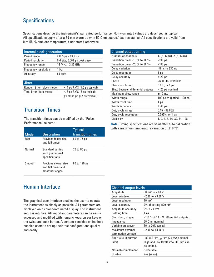
Channel output timing Number of channels 1, (81133A), 2 (81134A)Transition times (10 % to 90 %) < 90 ps Transition times (20 % to 80 %) < 60 ps Delay variation –5 ns to 230 nsDelay resolution 1 psDelay accuracy ± 20 psPhase –6000 to +279000°Phase resolution 0.01°, or 1 psSkew between differential outputs < 20 ps nominalMaximum skew range ± 10 ns, Width range 100 ps to (period - 100 ps)Width resolution 1 psWidth accuracy ± 40 ps Duty cycle range 0.15 - 99.85%Duty cycle resolution 0.002%, or 1 psDivide by 1, 2, 4, 8, 16, 32, 64, 128
Channel output levelsAmplitude 50 mV to 2.00 VLevel window –2.00 to +3.00 VLevel resolution 10 mVLevel accuracy 2% of setting ±20 mVAmplitude accuracy 2% ± 20 mVSettling time 1 nsOvershoot, ringing < 10 % ± 10 mV differential outputsImpedance 50 Ohm nominalVariable crossover 30 to 70% typicalMaximum external termination voltage
–2.00 to +3.00 V
Short circuit current –80 mA <= Isc <= 120 mA nominalLimit High and low levels into 50 Ohm can
be limited.Normal/complement SelectableDisable Yes (relay)
Note: Timing specifications are valid after auto calibration with a maximum temperature variation of ±10 °C.
Transition TimesThe transition times can be modified by the ‘Pulse Performance’ selector:
Internal clock generationPeriod range 298.5 ps - 66.6 nsPeriod resolution 6 digits, 0.001 ps best caseFrequency range 15 MHz - 3.35 GHzFrequency resolution 1 Hz Accuracy 50 ppm
JitterRandom jitter (clock mode) < 4 ps RMS (1.5 ps typical)Total jitter (data mode) < 5 ps RMS (2 ps typical)
(< 30 ps pp (12 ps typical))
Mode DescriptionTypical transition times
Fast Provides faster rise and fall times
60 to 75 ps
Normal Standard setting with guaranteed specifications
70 to 80 ps
Smooth Provides slower rise and fall times and smoother edges
80 to 120 ps
Specifications
Specifications describe the instrument’s warranted performance. Non-warranted values are described as typical. All specifications apply after a 30 min warm-up with 50 Ohm source/load resistance. All specifications are valid from 0 to 55 °C ambient temperature if not stated otherwise.

6 7
Pulse Pattern and Data Functionality
The 81133A and 81134A can generate an 8 KBit digital pattern in NRZ, RZ and R1 mode. Furthermore, the 81133A and 81134A can provide a hardware generated pseudo random binary sequence (PRBS) from 25 - 1 to 231 - 1.
Jitter Emulation (Delay Control Input)
Full control over the signal quality of pulse and data signals provides the Delay Control Input. With an external modulation source (e.g. Agilent 33250A) the amount and shape of signal jitter can be varied for stress tests or to emulate real world signals. The external source for jitter modulation is applied to this input. Jitter modulation can be turned on and off individually for each channel. Either one of two fixed sensitivities can be selected ± 25 ps or ± 250 ps resulting in a total of 50 ps or 500 ps. The ampli-tude of the modulated jitter is set by the voltage level of the signal applied to the Delay Control Input. The Variable Crossover Point feature provides additional control over the signal quality.
Data generationMemory depth 8 Kbit per channel/12 Mbit extended
memoryData format RZ/NRZ/R1
PRBS 2n-1 , n = 5, 6, 7, 8, 9, 10, 11, 12, 13, 14, 15, 23, 31PRBS Polynomial Comment25-1 X5 + X4 + X2 + X1 + 126-1 X6 + X5 + X3 + X2 + 1 ITU-T V.2927-1 X7 + X6 + 128-1 X8 + X7 + X3 + X2 + 129-1 X9 + X5 + 1 CCITT 0.153/ITU-T V.52210-1 X10 + X7 + 1 CCITT 0.152/ITU-T 0.152211-1 X11 + X19 + 1212-1 X12 + X9 + X8 + X5 + 1213-1 X13 + X12 + X10 + X9 + 1214-1 X14 + X13 + X10 + X9 + 1215-1 X15 + X14 + 1 CCITT 0.151/ITU-T 0.151223-1 X23 + X18 + 1 CCITT 0.151/ITU-T 0.151231-1 X31 + X28 + 1
Trigger outputAmplitude 50 mV to 2.00 VLevel window –2.00 V . . +3.00 VResolution 10 mVFormat fixed duty cycle, 50% nominalMaximum external voltage –2.00 V . . +3.00 VTransition times (20% to 80% of amplitude)
< 100 ps (< 70 ps typical)
Minimum output frequency 15 MHz/divider factorMode clock clock divided by 1,2,3, . .
231-1 or trigger on bit 0 of data
Disable Yes (relay)
Delay control inputInterface dc-coupledImpedance 50 Ohm nominalInput levels for full modulation range
±500 mV
Max input levels ±2.5 V Delay modulation range ±250 ps, ±25 ps, selectableModulation frequency 0 Hz - 200 MHz
Figure 2. Modulated Delay (Jitter) vs Voltage Level at Delay-Control-Input for ±250 ps and ±25 ps settings

8
Clock inputInterface ac-coupled with optional dc
terminationImpedance 50 OhmTermination voltage –2.0 V . . +3.0 VMinimum amplitude 300 mV, tr < 3 ns, 50% duty cycle;
sine: 6 dBmMaximum amplitude 3 Vpp , ± 5 VdcFrequency measurement YesPeriod range 299 ps . . 66.6 nsPeriod resolution 6 digits, 0.001 ps best caseFrequency range 15 MHz . . 3.35 GHzMeasurement resolution 100 kHzMeasurement accuracy 50 ppm
Start inputModes Start 1Interface dc-coupledImpedance 50 Ohm nominalTermination voltage –2.0 V . . 3.0 VTransitions < 1 nsThreshold –1.8 to +4 VMax. level window –2 to +5 V1. No fixed latency between assertion of start signal and start of
output signal
Figure 3.
Propagation delayClock input to trigger output 8.4 ns nominal, fixedTrigger output to channel output 32 ns nominal variable
Additonal featuresRemote interfaces SCPI over GPIB, LAN and USBStore/recall registers(Non volatile memory)
9 complete settings can be saved. The last settings are saved when power is turned off.
General informationOperating temperature 0 to +55 °CStorage temperature –40 to +70 °CHumidity 95% R.H. (0 to +40 °C)Warm up 30 MinutesEMC Class APower 100V to 240V AC nom.;
200 VA max.; 47 Hz to 63 HzNet weight 14.8 kg (32.6 lbs)Shipping weight 19 kg (41.9 lbs)Dimensions 145 x 426 x 553 (mm)
5.7 x 16.75 x 21.75 (in)Recalibration period 3 years recommended
Jitter modulatedwith rectangle-wave
Jitter modulatedwith sine-wave
Jitter modulatedwith noise-generatorVariable cross over
point at 70%
33250A modulationsource
81133-34A pulse-/pattern generator
Device undertest
InfiniumReference
Delay control input
8 9
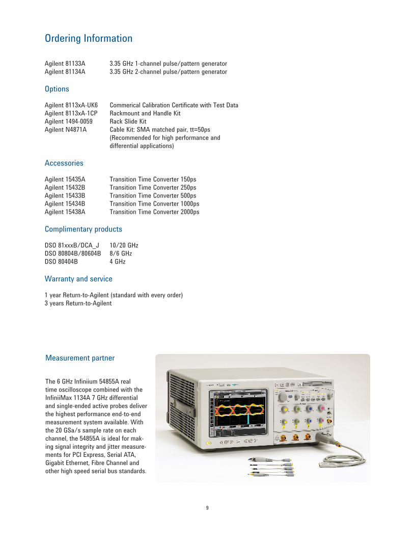
Ordering Information
Agilent 81133A 3.35 GHz 1-channel pulse/pattern generatorAgilent 81134A 3.35 GHz 2-channel pulse/pattern generator
Options
Agilent 8113xA-UK6 Commerical Calibration Certificate with Test DataAgilent 8113xA-1CP Rackmount and Handle KitAgilent 1494-0059 Rack Slide KitAgilent N4871A Cable Kit: SMA matched pair, tt=50ps (Recommended for high performance and differential applications)
Accessories
Agilent 15435A Transition Time Converter 150psAgilent 15432B Transition Time Converter 250psAgilent 15433B Transition Time Converter 500psAgilent 15434B Transition Time Converter 1000psAgilent 15438A Transition Time Converter 2000ps
Complimentary products
DSO 81xxxB/DCA_J 10/20 GHzDSO 80804B/80604B 8/6 GHzDSO 80404B 4 GHz
Warranty and service
1 year Return-to-Agilent (standard with every order)3 years Return-to-Agilent
Measurement partner
The 6 GHz Infiniium 54855A real time oscilloscope combined with the InfiniiMax 1134A 7 GHz differential and single-ended active probes deliver the highest performance end-to-end measurement system available. With the 20 GSa/s sample rate on each channel, the 54855A is ideal for mak-ing signal integrity and jitter measure-ments for PCI Express, Serial ATA, Gigabit Ethernet, Fibre Channel and other high speed serial bus standards.
Related literature Publication no.
Agilent Family 5980-0489Eof Pulse Pattern GeneratorsBrochure
Agilent 81100 5980-1215EFamily Pulse Pattern, Product Overview
Generating and 5988-9411ENMeasuring Jitter Product Note
Agilent 81133A/ 5988-9591EN81134A Extended Pattern MemoryProduct Note
For more information, please visit us at: www.agilent.com/find/pulse_generator
Product specifications and descrip-tions in this document subject to change without notice. For the latest version of this document, please visit our website at www.agilent.com/find/pulse_generator and go to the Key Library Information area or insert the publication number (5988-5549EN) into the search engine.
Agilent Email Updates
www.agilent.com/find/emailupdatesGet the latest information on the products and applications you select.
www.agilent.comwww.agilent.com/find/pulse_generator
Agilent Advantage Services is committed to your success throughout your equip-ment’s lifetime. To keep you competitive, we continually invest in tools and processes that speed up calibration and repair and reduce your cost of ownership. You can also use Infoline Web Services to manage equipment and services more effectively. By sharing our measurement and service expertise, we help you create the products that change our world.
www.agilent.com/quality
www.agilent.com/find/advantageservices
For more information on Agilent Technologies’ products, applications or services, please contact your local Agilent office. The complete list is available at:www.agilent.com/find/contactus
AmericasCanada (877) 894 4414 Brazil (11) 4197 3600Mexico 01800 5064 800 United States (800) 829 4444
Asia PacificAustralia 1 800 629 485China 800 810 0189Hong Kong 800 938 693India 1 800 112 929Japan 0120 (421) 345Korea 080 769 0800Malaysia 1 800 888 848Singapore 1 800 375 8100Taiwan 0800 047 866Other AP Countries (65) 375 8100
europe & Middle eastBelgium 32 (0) 2 404 93 40 Denmark 45 45 80 12 15Finland 358 (0) 10 855 2100France 0825 010 700* *0.125 €/minuteGermany 49 (0) 7031 464 6333 Ireland 1890 924 204Israel 972-3-9288-504/544Italy 39 02 92 60 8484Netherlands 31 (0) 20 547 2111Spain 34 (91) 631 3300Sweden 0200-88 22 55United Kingdom 44 (0) 118 927 6201For other unlisted countries: www.agilent.com/find/contactusRevised: January 6, 2012
Product specifications and descriptions in this document subject to change without notice.
© Agilent Technologies, Inc. 2007, 2012Published in USA, March 14, 20125988-5549EN