Embed Size (px)
Citation preview

x
TAP2500, TAP3500, and TAP40002.5 GHz, 3.5 GHz, and 4 GHz ProbesZZZ
Instruction Manual
*P071183602*
071-1836-02


TAP2500, TAP3500, and TAP40002.5 GHz, 3.5 GHz, and 4 GHz ProbesZZZ
Instruction Manual
xx
www.tek.com071-1836-02
Copyright © Tektronix. All rights reserved. Licensed software products are owned by Tektronix or its subsidiaries or suppliers, and are protected bynational copyright laws and international treaty provisions.
Tektronix products are covered by U.S. and foreign patents, issued and pending. Information in this publication supersedes that in all previouslypublished material. Specifications and price change privileges reserved.
TEKTRONIX and TEK are registered trademarks of Tektronix, Inc.
TekVPI is a trademark of Tektronix, Inc.
Contacting TektronixTektronix, Inc.14150 SW Karl Braun DriveP.O. Box 500Beaverton, OR 97077USA
For product information, sales, service, and technical support:In North America, call 1-800-833-9200.Worldwide, visit www.tek.com to find contacts in your area.
WarrantyTektronix warrants that this product will be free from defects in materials and workmanship for a period of one (1) year from the date of shipment. Ifany such product proves defective during this warranty period, Tektronix, at its option, either will repair the defective product without charge for partsand labor, or will provide a replacement in exchange for the defective product. Parts, modules and replacement products used by Tektronix forwarranty work may be new or reconditioned to like new performance. All replaced parts, modules and products become the property of Tektronix.
In order to obtain service under this warranty, Customer must notify Tektronix of the defect before the expiration of the warranty period and makesuitable arrangements for the performance of service. Customer shall be responsible for packaging and shipping the defective product to the servicecenter designated by Tektronix, with shipping charges prepaid. Tektronix shall pay for the return of the product to Customer if the shipment is to alocation within the country in which the Tektronix service center is located. Customer shall be responsible for paying all shipping charges, duties,taxes, and any other charges for products returned to any other locations.
This warranty shall not apply to any defect, failure or damage caused by improper use or improper or inadequate maintenance and care. Tektronixshall not be obligated to furnish service under this warranty a) to repair damage resulting from attempts by personnel other than Tektronixrepresentatives to install, repair or service the product; b) to repair damage resulting from improper use or connection to incompatible equipment; c) torepair any damage or malfunction caused by the use of non-Tektronix supplies; or d) to service a product that has been modified or integrated withother products when the effect of such modification or integration increases the time or difficulty of servicing the product.
THIS WARRANTY IS GIVEN BY TEKTRONIX WITH RESPECT TO THE PRODUCT IN LIEU OF ANY OTHER WARRANTIES, EXPRESS ORIMPLIED. TEKTRONIX AND ITS VENDORS DISCLAIM ANY IMPLIED WARRANTIES OF MERCHANTABILITY OR FITNESS FOR A PARTICULARPURPOSE. TEKTRONIX' RESPONSIBILITY TO REPAIR OR REPLACE DEFECTIVE PRODUCTS IS THE SOLE AND EXCLUSIVE REMEDYPROVIDED TO THE CUSTOMER FOR BREACH OF THIS WARRANTY. TEKTRONIX AND ITS VENDORS WILL NOT BE LIABLE FOR ANYINDIRECT, SPECIAL, INCIDENTAL, OR CONSEQUENTIAL DAMAGES IRRESPECTIVE OF WHETHER TEKTRONIX OR THE VENDOR HASADVANCE NOTICE OF THE POSSIBILITY OF SUCH DAMAGES.[W2 – 15AUG04]

Table of Contents
Table of ContentsGeneral safety summary . . . . . . . . . . . . . . . . . . . . . . . . . . . . . . . . . . . . . . . . . . . . . . . . . . . . . . . . . . . . . . . . . . . . . . . . . . . . . . . . . . . . . . . . . . . . . . . . . . . . . . . . . . . . . . . . . . . . v
Service safety summary . . . . . . . . . . . . . . . . . . . . . . . . . . . . . . . . . . . . . . . . . . . . . . . . . . . . . . . . . . . . . . . . . . . . . . . . . . . . . . . . . . . . . . . . . . . . . . . . . . . . . . . . . . . . . . . . . . . . ix
Environmental Considerations . . . . . . . . . . . . . . . . . . . . . . . . . . . . . . . . . . . . . . . . . . . . . . . . . . . . . . . . . . . . . . . . . . . . . . . . . . . . . . . . . . . . . . . . . . . . . . . . . . . . . . . . . . . . . . x
Preface. . . . . . . . . . . . . . . . . . . . . . . . . . . . . . . . . . . . . . . . . . . . . . . . . . . . . . . . . . . . . . . . . . . . . . . . . . . . . . . . . . . . . . . . . . . . . . . . . . . . . . . . . . . . . . . . . . . . . . . . . . . . . . . . . . . . . . xiDocumentation . . . . . . . . . . . . . . . . . . . . . . . . . . . . . . . . . . . . . . . . . . . . . . . . . . . . . . . . . . . . . . . . . . . . . . . . . . . . . . . . . . . . . . . . . . . . . . . . . . . . . . . . . . . . . . . . . . . . . . . . xiConventions used in this manual . . . . . . . . . . . . . . . . . . . . . . . . . . . . . . . . . . . . . . . . . . . . . . . . . . . . . . . . . . . . . . . . . . . . . . . . . . . . . . . . . . . . . . . . . . . . . . . . . . . . . xiReturning the probe for servicing. . . . . . . . . . . . . . . . . . . . . . . . . . . . . . . . . . . . . . . . . . . . . . . . . . . . . . . . . . . . . . . . . . . . . . . . . . . . . . . . . . . . . . . . . . . . . . . . . . . . xii
Key features . . . . . . . . . . . . . . . . . . . . . . . . . . . . . . . . . . . . . . . . . . . . . . . . . . . . . . . . . . . . . . . . . . . . . . . . . . . . . . . . . . . . . . . . . . . . . . . . . . . . . . . . . . . . . . . . . . . . . . . . . . . . . . . . 1
Installation . . . . . . . . . . . . . . . . . . . . . . . . . . . . . . . . . . . . . . . . . . . . . . . . . . . . . . . . . . . . . . . . . . . . . . . . . . . . . . . . . . . . . . . . . . . . . . . . . . . . . . . . . . . . . . . . . . . . . . . . . . . . . . . . . . 2Connecting to the host instrument. . . . . . . . . . . . . . . . . . . . . . . . . . . . . . . . . . . . . . . . . . . . . . . . . . . . . . . . . . . . . . . . . . . . . . . . . . . . . . . . . . . . . . . . . . . . . . . . . . . . 2Probe controls and indicators. . . . . . . . . . . . . . . . . . . . . . . . . . . . . . . . . . . . . . . . . . . . . . . . . . . . . . . . . . . . . . . . . . . . . . . . . . . . . . . . . . . . . . . . . . . . . . . . . . . . . . . . . 3
Functional check. . . . . . . . . . . . . . . . . . . . . . . . . . . . . . . . . . . . . . . . . . . . . . . . . . . . . . . . . . . . . . . . . . . . . . . . . . . . . . . . . . . . . . . . . . . . . . . . . . . . . . . . . . . . . . . . . . . . . . . . . . . . 6Required equipment . . . . . . . . . . . . . . . . . . . . . . . . . . . . . . . . . . . . . . . . . . . . . . . . . . . . . . . . . . . . . . . . . . . . . . . . . . . . . . . . . . . . . . . . . . . . . . . . . . . . . . . . . . . . . . . . . . 6
Calibration . . . . . . . . . . . . . . . . . . . . . . . . . . . . . . . . . . . . . . . . . . . . . . . . . . . . . . . . . . . . . . . . . . . . . . . . . . . . . . . . . . . . . . . . . . . . . . . . . . . . . . . . . . . . . . . . . . . . . . . . . . . . . . . . . . 8Prerequisites . . . . . . . . . . . . . . . . . . . . . . . . . . . . . . . . . . . . . . . . . . . . . . . . . . . . . . . . . . . . . . . . . . . . . . . . . . . . . . . . . . . . . . . . . . . . . . . . . . . . . . . . . . . . . . . . . . . . . . . . . . 8Required equipment . . . . . . . . . . . . . . . . . . . . . . . . . . . . . . . . . . . . . . . . . . . . . . . . . . . . . . . . . . . . . . . . . . . . . . . . . . . . . . . . . . . . . . . . . . . . . . . . . . . . . . . . . . . . . . . . . . 8Test procedure . . . . . . . . . . . . . . . . . . . . . . . . . . . . . . . . . . . . . . . . . . . . . . . . . . . . . . . . . . . . . . . . . . . . . . . . . . . . . . . . . . . . . . . . . . . . . . . . . . . . . . . . . . . . . . . . . . . . . . . . 9
Basic operation . . . . . . . . . . . . . . . . . . . . . . . . . . . . . . . . . . . . . . . . . . . . . . . . . . . . . . . . . . . . . . . . . . . . . . . . . . . . . . . . . . . . . . . . . . . . . . . . . . . . . . . . . . . . . . . . . . . . . . . . . . . . 12Probe head assembly. . . . . . . . . . . . . . . . . . . . . . . . . . . . . . . . . . . . . . . . . . . . . . . . . . . . . . . . . . . . . . . . . . . . . . . . . . . . . . . . . . . . . . . . . . . . . . . . . . . . . . . . . . . . . . . . 12
TAP2500, TAP3500, and TAP4000 Instruction Manual i
Table of Contents
Probe input . . . . . . . . . . . . . . . . . . . . . . . . . . . . . . . . . . . . . . . . . . . . . . . . . . . . . . . . . . . . . . . . . . . . . . . . . . . . . . . . . . . . . . . . . . . . . . . . . . . . . . . . . . . . . . . . . . . . . . . . . . . 13Probe offset . . . . . . . . . . . . . . . . . . . . . . . . . . . . . . . . . . . . . . . . . . . . . . . . . . . . . . . . . . . . . . . . . . . . . . . . . . . . . . . . . . . . . . . . . . . . . . . . . . . . . . . . . . . . . . . . . . . . . . . . . . 15
Accessories and options . . . . . . . . . . . . . . . . . . . . . . . . . . . . . . . . . . . . . . . . . . . . . . . . . . . . . . . . . . . . . . . . . . . . . . . . . . . . . . . . . . . . . . . . . . . . . . . . . . . . . . . . . . . . . . . . . . 17Using standard accessories . . . . . . . . . . . . . . . . . . . . . . . . . . . . . . . . . . . . . . . . . . . . . . . . . . . . . . . . . . . . . . . . . . . . . . . . . . . . . . . . . . . . . . . . . . . . . . . . . . . . . . . . . 17Optional accessories. . . . . . . . . . . . . . . . . . . . . . . . . . . . . . . . . . . . . . . . . . . . . . . . . . . . . . . . . . . . . . . . . . . . . . . . . . . . . . . . . . . . . . . . . . . . . . . . . . . . . . . . . . . . . . . . . 27Options . . . . . . . . . . . . . . . . . . . . . . . . . . . . . . . . . . . . . . . . . . . . . . . . . . . . . . . . . . . . . . . . . . . . . . . . . . . . . . . . . . . . . . . . . . . . . . . . . . . . . . . . . . . . . . . . . . . . . . . . . . . . . . . 29
Probing principles. . . . . . . . . . . . . . . . . . . . . . . . . . . . . . . . . . . . . . . . . . . . . . . . . . . . . . . . . . . . . . . . . . . . . . . . . . . . . . . . . . . . . . . . . . . . . . . . . . . . . . . . . . . . . . . . . . . . . . . . . . 30Ground lead length . . . . . . . . . . . . . . . . . . . . . . . . . . . . . . . . . . . . . . . . . . . . . . . . . . . . . . . . . . . . . . . . . . . . . . . . . . . . . . . . . . . . . . . . . . . . . . . . . . . . . . . . . . . . . . . . . . 30
Ground lead inductance . . . . . . . . . . . . . . . . . . . . . . . . . . . . . . . . . . . . . . . . . . . . . . . . . . . . . . . . . . . . . . . . . . . . . . . . . . . . . . . . . . . . . . . . . . . . . . . . . . . . . . . . . . . . . . . . . . . 31
Low-inductance grounding . . . . . . . . . . . . . . . . . . . . . . . . . . . . . . . . . . . . . . . . . . . . . . . . . . . . . . . . . . . . . . . . . . . . . . . . . . . . . . . . . . . . . . . . . . . . . . . . . . . . . . . . . . . . . . . . 32
SureFoot™ Grounding . . . . . . . . . . . . . . . . . . . . . . . . . . . . . . . . . . . . . . . . . . . . . . . . . . . . . . . . . . . . . . . . . . . . . . . . . . . . . . . . . . . . . . . . . . . . . . . . . . . . . . . . . . . . . . . . . . . . 33
Probe tip test points . . . . . . . . . . . . . . . . . . . . . . . . . . . . . . . . . . . . . . . . . . . . . . . . . . . . . . . . . . . . . . . . . . . . . . . . . . . . . . . . . . . . . . . . . . . . . . . . . . . . . . . . . . . . . . . . . . . . . . . 34
Probe tip stabilization. . . . . . . . . . . . . . . . . . . . . . . . . . . . . . . . . . . . . . . . . . . . . . . . . . . . . . . . . . . . . . . . . . . . . . . . . . . . . . . . . . . . . . . . . . . . . . . . . . . . . . . . . . . . . . . . . . . . . . 35
Specifications . . . . . . . . . . . . . . . . . . . . . . . . . . . . . . . . . . . . . . . . . . . . . . . . . . . . . . . . . . . . . . . . . . . . . . . . . . . . . . . . . . . . . . . . . . . . . . . . . . . . . . . . . . . . . . . . . . . . . . . . . . . . . . 36Warranted characteristics. . . . . . . . . . . . . . . . . . . . . . . . . . . . . . . . . . . . . . . . . . . . . . . . . . . . . . . . . . . . . . . . . . . . . . . . . . . . . . . . . . . . . . . . . . . . . . . . . . . . . . . . . . . . 37Typical characteristics . . . . . . . . . . . . . . . . . . . . . . . . . . . . . . . . . . . . . . . . . . . . . . . . . . . . . . . . . . . . . . . . . . . . . . . . . . . . . . . . . . . . . . . . . . . . . . . . . . . . . . . . . . . . . . . 38Nominal characteristics . . . . . . . . . . . . . . . . . . . . . . . . . . . . . . . . . . . . . . . . . . . . . . . . . . . . . . . . . . . . . . . . . . . . . . . . . . . . . . . . . . . . . . . . . . . . . . . . . . . . . . . . . . . . . . 44
Performance verification. . . . . . . . . . . . . . . . . . . . . . . . . . . . . . . . . . . . . . . . . . . . . . . . . . . . . . . . . . . . . . . . . . . . . . . . . . . . . . . . . . . . . . . . . . . . . . . . . . . . . . . . . . . . . . . . . . . 45Equipment required . . . . . . . . . . . . . . . . . . . . . . . . . . . . . . . . . . . . . . . . . . . . . . . . . . . . . . . . . . . . . . . . . . . . . . . . . . . . . . . . . . . . . . . . . . . . . . . . . . . . . . . . . . . . . . . . . . 45Equipment setup . . . . . . . . . . . . . . . . . . . . . . . . . . . . . . . . . . . . . . . . . . . . . . . . . . . . . . . . . . . . . . . . . . . . . . . . . . . . . . . . . . . . . . . . . . . . . . . . . . . . . . . . . . . . . . . . . . . . . 47DC gain accuracy . . . . . . . . . . . . . . . . . . . . . . . . . . . . . . . . . . . . . . . . . . . . . . . . . . . . . . . . . . . . . . . . . . . . . . . . . . . . . . . . . . . . . . . . . . . . . . . . . . . . . . . . . . . . . . . . . . . . 48
ii TAP2500, TAP3500, and TAP4000 Instruction Manual
Table of Contents
Rise time . . . . . . . . . . . . . . . . . . . . . . . . . . . . . . . . . . . . . . . . . . . . . . . . . . . . . . . . . . . . . . . . . . . . . . . . . . . . . . . . . . . . . . . . . . . . . . . . . . . . . . . . . . . . . . . . . . . . . . . . . . . . . 51Test record . . . . . . . . . . . . . . . . . . . . . . . . . . . . . . . . . . . . . . . . . . . . . . . . . . . . . . . . . . . . . . . . . . . . . . . . . . . . . . . . . . . . . . . . . . . . . . . . . . . . . . . . . . . . . . . . . . . . . . . . . . . 59
Maintenance . . . . . . . . . . . . . . . . . . . . . . . . . . . . . . . . . . . . . . . . . . . . . . . . . . . . . . . . . . . . . . . . . . . . . . . . . . . . . . . . . . . . . . . . . . . . . . . . . . . . . . . . . . . . . . . . . . . . . . . . . . . . . . . 60Error condition . . . . . . . . . . . . . . . . . . . . . . . . . . . . . . . . . . . . . . . . . . . . . . . . . . . . . . . . . . . . . . . . . . . . . . . . . . . . . . . . . . . . . . . . . . . . . . . . . . . . . . . . . . . . . . . . . . . . . . . 60Replacement parts. . . . . . . . . . . . . . . . . . . . . . . . . . . . . . . . . . . . . . . . . . . . . . . . . . . . . . . . . . . . . . . . . . . . . . . . . . . . . . . . . . . . . . . . . . . . . . . . . . . . . . . . . . . . . . . . . . . 60Cleaning. . . . . . . . . . . . . . . . . . . . . . . . . . . . . . . . . . . . . . . . . . . . . . . . . . . . . . . . . . . . . . . . . . . . . . . . . . . . . . . . . . . . . . . . . . . . . . . . . . . . . . . . . . . . . . . . . . . . . . . . . . . . . . 61
Index
TAP2500, TAP3500, and TAP4000 Instruction Manual iii

Table of Contents
iv TAP2500, TAP3500, and TAP4000 Instruction Manual
General safety summary
General safety summaryReview the following safety precautions to avoid injury and prevent damage to this product or any products connected to it.
To avoid potential hazards, use this product only as specified.
Only qualified personnel should perform service procedures.
While using this product, you may need to access other parts of a larger system. Read the safety sections of the other componentmanuals for warnings and cautions related to operating the system.
To avoid fire or personal injuryConnect and disconnect properly. Do not connect or disconnect probes or test leads while they are connected to a voltagesource.
Connect and disconnect properly. Connect the probe output to the measurement instrument before connecting the probe to thecircuit under test. Connect the probe reference lead to the circuit under test before connecting the probe input. Disconnect the probeinput and the probe reference lead from the circuit under test before disconnecting the probe from the measurement instrument.
Ground the product. This product is indirectly grounded through the grounding conductor of the mainframe power cord. To avoidelectric shock, the grounding conductor must be connected to earth ground. Before making connections to the input or outputterminals of the product, ensure that the product is properly grounded.
Observe all terminal ratings. To avoid fire or shock hazard, observe all ratings and markings on the product. Consult the productmanual for further ratings information before making connections to the product.
Connect the probe reference lead to earth ground only.
Do not apply a potential to any terminal, including the common terminal, that exceeds the maximum rating of that terminal.
TAP2500, TAP3500, and TAP4000 Instruction Manual v
General safety summary
Do not operate without covers. Do not operate this product with covers or panels removed.
Do not operate with suspected failures. If you suspect that there is damage to this product, have it inspected by qualifiedservice personnel.
Avoid exposed circuitry. Do not touch exposed connections and components when power is present.
Do not operate in wet/damp conditions.
Do not operate in an explosive atmosphere.
Keep product surfaces clean and dry.
vi TAP2500, TAP3500, and TAP4000 Instruction Manual
General safety summary
Terms in this manualThese terms may appear in this manual:
WARNING. Warning statements identify conditions or practices that could result in injury or loss of life.
CAUTION. Caution statements identify conditions or practices that could result in damage to this product or other property.
Symbols and terms on the productThese terms may appear on the product:
DANGER indicates an injury hazard immediately accessible as you read the marking.
WARNING indicates an injury hazard not immediately accessible as you read the marking.
CAUTION indicates a hazard to property including the product.
TAP2500, TAP3500, and TAP4000 Instruction Manual vii
General safety summary
The following symbol(s) may appear on the product:
viii TAP2500, TAP3500, and TAP4000 Instruction Manual
Service safety summary
Service safety summaryOnly qualified personnel should perform service procedures. Read this Service safety summary and the General safety summarybefore performing any service procedures.
Do not service alone. Do not perform internal service or adjustments of this product unless another person capable of renderingfirst aid and resuscitation is present.
Disconnect power. To avoid electric shock, switch off the instrument power, then disconnect the power cord from the mainspower.
Use care when servicing with power on. Dangerous voltages or currents may exist in this product. Disconnect power, removebattery (if applicable), and disconnect test leads before removing protective panels, soldering, or replacing components.
To avoid electric shock, do not touch exposed connections.
TAP2500, TAP3500, and TAP4000 Instruction Manual ix
Environmental Considerations
Environmental ConsiderationsThis section provides information about the environmental impact of the product.
Restriction of hazardous substancesComplies with RoHS2 Directive 2011/65/EU.
Product End-of-Life HandlingObserve the following guidelines when recycling an instrument or component:
Equipment Recycling. Production of this equipment required the extraction and use of natural resources. The equipment maycontain substances that could be harmful to the environment or human health if improperly handled at the product’s end of life. Toavoid release of such substances into the environment and to reduce the use of natural resources, we encourage you to recycle thisproduct in an appropriate system that will ensure that most of the materials are reused or recycled appropriately.
This symbol indicates that this product complies with the applicable European Union requirements according toDirectives 2012/19/EU and 2006/66/EC on waste electrical and electronic equipment (WEEE) and batteries. Forinformation about recycling options, check the Tektronix Web site (www.tek.com/productrecycling).
x TAP2500, TAP3500, and TAP4000 Instruction Manual
Preface
PrefaceThis manual describes the installation and operation of the TAP2500, TAP3500, and TAP4000 active probes. Basic probe operationsand concepts are presented in this manual. The DPO7000 series oscilloscope and the TAP2500 probe is used in all illustrations inthis manual, unless noted otherwise. You can access this document and other related information from the Tektronix Web site.
Documentation
To read about Use these documents *
TAP2500, TAP3500, and TAP4000 Probes: First Time Operation, FunctionalCheck, Operating Basics, Specifications, Performance Verification
Read this Instruction Manual.
In-depth oscilloscope operation, user interface help, GPIB commands Access the online help from the Help menu onthe host instrument.
* To access the documentation that is installed on your instrument, click Start in the taskbar and select Programs > TekApplications.
Conventions used in this manualThe following icon is used throughout this manual to indicate a step sequence.
TAP2500, TAP3500, and TAP4000 Instruction Manual xi
Preface
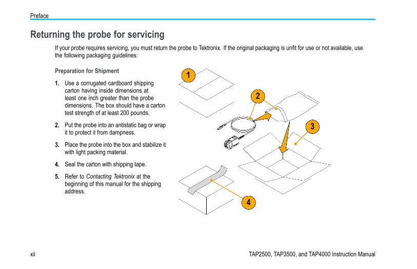
Returning the probe for servicingIf your probe requires servicing, you must return the probe to Tektronix. If the original packaging is unfit for use or not available, usethe following packaging guidelines:
Preparation for Shipment
1. Use a corrugated cardboard shippingcarton having inside dimensions atleast one inch greater than the probedimensions. The box should have a cartontest strength of at least 200 pounds.
2. Put the probe into an antistatic bag or wrapit to protect it from dampness.
3. Place the probe into the box and stabilize itwith light packing material.
4. Seal the carton with shipping tape.
5. Refer to Contacting Tektronix at thebeginning of this manual for the shippingaddress.
xii TAP2500, TAP3500, and TAP4000 Instruction Manual

Key features
Key featuresThe TAP2500, TAP3500, and TAP4000 active probes enable you to make accurate measurements with minimal circuit loadingfrom DC to 2.5 GHz, 3.5 GHz, and 4 GHz respectively, using oscilloscopes featuring the new Tektronix TekVPI oscilloscopeinterface. Key features include:
BandwidthDC to ≥2.5 GHz (TAP2500)DC to ≥3.5 GHz (TAP3500)DC to ≥4 GHz (TAP4000)
±4 Volts Dynamic Range with ±10 voltoffset capability
10X Attenuation
40 kΩ Input Resistance
<0.8 pF Input Capacitance
TekVPI Interface
Small, low-mass probe head for probingdense circuitry
TAP2500, TAP3500, and TAP4000 Instruction Manual 1
Installation
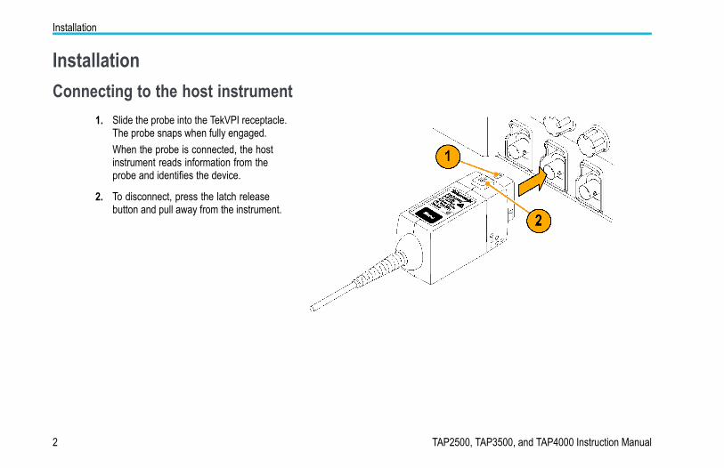
InstallationConnecting to the host instrument
1. Slide the probe into the TekVPI receptacle.The probe snaps when fully engaged.When the probe is connected, the hostinstrument reads information from theprobe and identifies the device.
2. To disconnect, press the latch releasebutton and pull away from the instrument.
2 TAP2500, TAP3500, and TAP4000 Instruction Manual
Installation
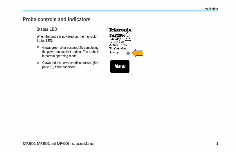
Probe controls and indicatorsStatus LEDWhen the probe is powered on, the multicolorStatus LED:
Glows green after successfully completingthe power-on self test routine. The probe isin normal operating mode.
Glows red if an error condition exists. (Seepage 60, Error condition.)
TAP2500, TAP3500, and TAP4000 Instruction Manual 3
Installation
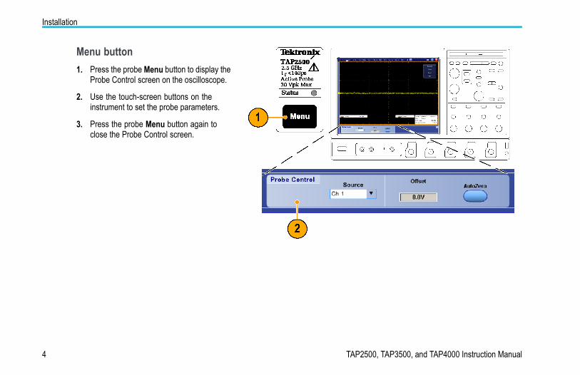
Menu button1. Press the probe Menu button to display the
Probe Control screen on the oscilloscope.
2. Use the touch-screen buttons on theinstrument to set the probe parameters.
3. Press the probe Menu button again toclose the Probe Control screen.
4 TAP2500, TAP3500, and TAP4000 Instruction Manual
Installation
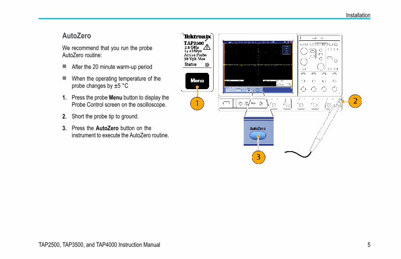
AutoZeroWe recommend that you run the probeAutoZero routine:
After the 20 minute warm-up period
When the operating temperature of theprobe changes by ±5 °C
1. Press the probe Menu button to display theProbe Control screen on the oscilloscope.
2. Short the probe tip to ground.
3. Press the AutoZero button on theinstrument to execute the AutoZero routine.
TAP2500, TAP3500, and TAP4000 Instruction Manual 5
Functional check
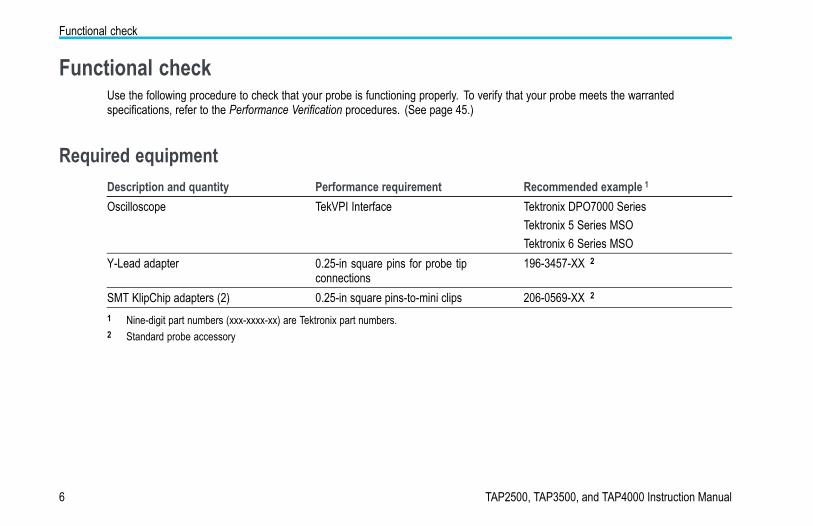
Functional checkUse the following procedure to check that your probe is functioning properly. To verify that your probe meets the warrantedspecifications, refer to the Performance Verification procedures. (See page 45.)
Required equipmentDescription and quantity Performance requirement Recommended example 1
Oscilloscope TekVPI Interface Tektronix DPO7000 SeriesTektronix 5 Series MSOTektronix 6 Series MSO
Y-Lead adapter 0.25-in square pins for probe tipconnections
196-3457-XX 2
SMT KlipChip adapters (2) 0.25-in square pins-to-mini clips 206-0569-XX 2
1 Nine-digit part numbers (xxx-xxxx-xx) are Tektronix part numbers.2 Standard probe accessory
6 TAP2500, TAP3500, and TAP4000 Instruction Manual
Functional check
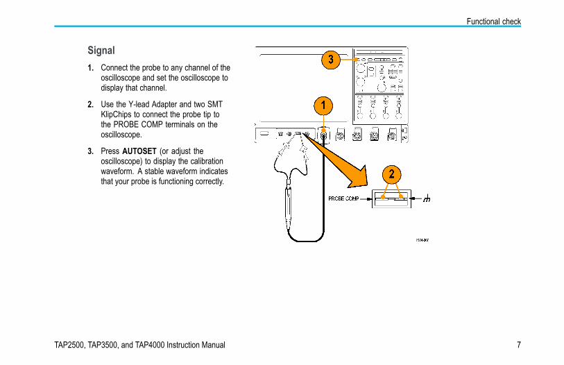
Signal1. Connect the probe to any channel of the
oscilloscope and set the oscilloscope todisplay that channel.
2. Use the Y-lead Adapter and two SMTKlipChips to connect the probe tip tothe PROBE COMP terminals on theoscilloscope.
3. Press AUTOSET (or adjust theoscilloscope) to display the calibrationwaveform. A stable waveform indicatesthat your probe is functioning correctly.
TAP2500, TAP3500, and TAP4000 Instruction Manual 7
Calibration
CalibrationThe probe calibration routine minimizes your measurement errors by optimizing the gain and offset of the probe and oscilloscopecombination. We recommend that you repeat the probe calibration on each channel that you use. Individual calibration constantsare stored for each probe on each channel.
PrerequisitesThe equipment must be warmed up for 20 minutes, and the calibration status of the host instrument must be pass.
Required equipmentThe required equipment for calibration is the same as for the functional check. (See page 6, Required equipment.)
8 TAP2500, TAP3500, and TAP4000 Instruction Manual
Calibration
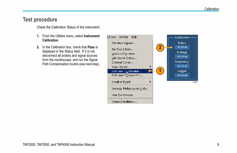
Test procedureCheck the Calibration Status of the instrument:
1. From the Utilities menu, select InstrumentCalibration.
2. In the Calibration box, check that Pass isdisplayed in the Status field. If it is not,disconnect all probes and signal sourcesfrom the oscilloscope, and run the SignalPath Compensation routine (see next step).
TAP2500, TAP3500, and TAP4000 Instruction Manual 9
Calibration
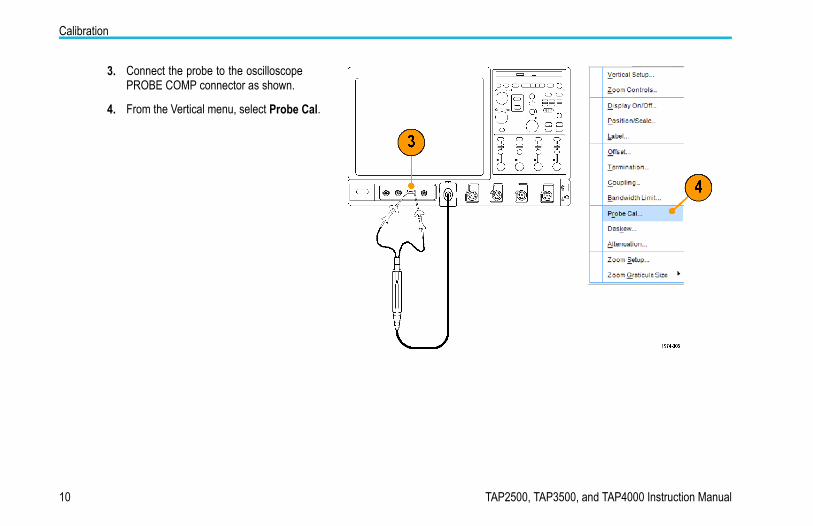
3. Connect the probe to the oscilloscopePROBE COMP connector as shown.
4. From the Vertical menu, select Probe Cal.
10 TAP2500, TAP3500, and TAP4000 Instruction Manual

Calibration
5. When the Probe Setup screen appears,select Clear ProbeCal, and then selectCalibrate Probe.The probe calibration routine begins. Whenthe routine completes, a notifier appears.Close the notifier and begin using yourprobe.
TAP2500, TAP3500, and TAP4000 Instruction Manual 11
Basic operation
Basic operationFollow these operating guidelines to get the best performance from your probe.
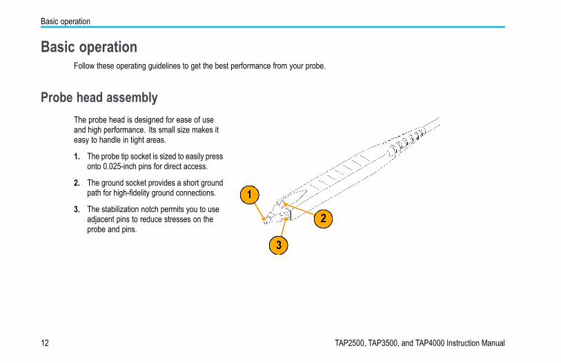
Probe head assemblyThe probe head is designed for ease of useand high performance. Its small size makes iteasy to handle in tight areas.
1. The probe tip socket is sized to easily pressonto 0.025-inch pins for direct access.
2. The ground socket provides a short groundpath for high-fidelity ground connections.
3. The stabilization notch permits you to useadjacent pins to reduce stresses on theprobe and pins.
12 TAP2500, TAP3500, and TAP4000 Instruction Manual
Basic operation
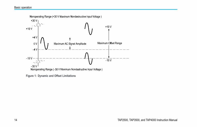
Probe inputThe probe is electrically protected against static voltage. However, applying voltages above its design limits may damage theprobe tip amplifier. (See Figure 1 on page 14.)
Input Linear Dynamic RangeThe probe head amplifier used by the probe has a limited linear operating range. To keep the input linearity error less than 1% youmust limit the signal input voltage to ±4 V (including any DC offset).
TAP2500, TAP3500, and TAP4000 Instruction Manual 13
Basic operation
Figure 1: Dynamic and Offset Limitations
14 TAP2500, TAP3500, and TAP4000 Instruction Manual
Basic operation
Probe offsetThe probe offset is adjustable for operation within the linear range of the probe, and to increase the sensitivity of the probe athigher DC measurement voltages. Using the offset to cancel DC signal components enables optimal probe performance. (SeeFigure 1 on page 14.)
NOTE. See your oscilloscope manual for specific instructions on using the offset control.
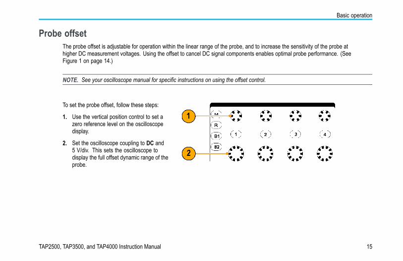
To set the probe offset, follow these steps:
1. Use the vertical position control to set azero reference level on the oscilloscopedisplay.
2. Set the oscilloscope coupling to DC and5 V/div. This sets the oscilloscope todisplay the full offset dynamic range of theprobe.
TAP2500, TAP3500, and TAP4000 Instruction Manual 15
Basic operation
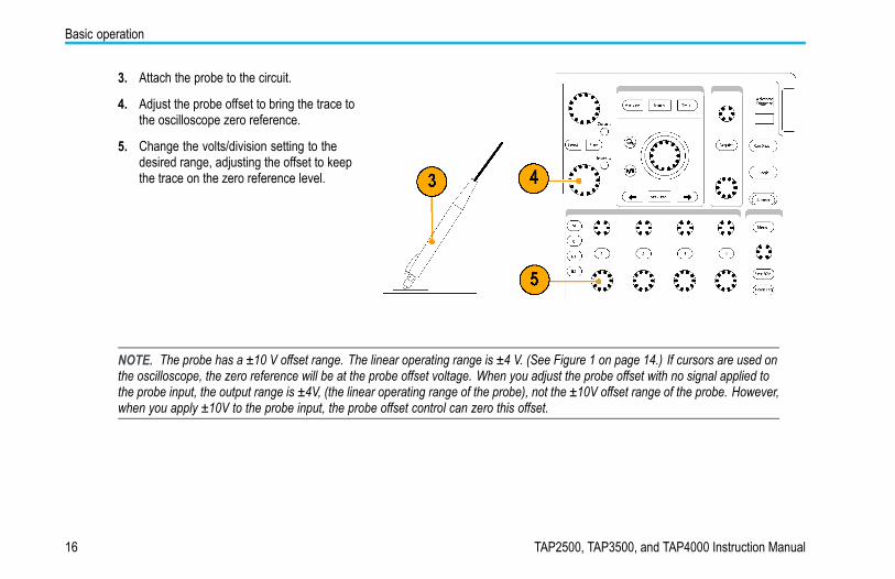
3. Attach the probe to the circuit.
4. Adjust the probe offset to bring the trace tothe oscilloscope zero reference.
5. Change the volts/division setting to thedesired range, adjusting the offset to keepthe trace on the zero reference level.
NOTE. The probe has a ±10 V offset range. The linear operating range is ±4 V. (See Figure 1 on page 14.) If cursors are used onthe oscilloscope, the zero reference will be at the probe offset voltage. When you adjust the probe offset with no signal applied tothe probe input, the output range is ±4V, (the linear operating range of the probe), not the ±10V offset range of the probe. However,when you apply ±10V to the probe input, the probe offset control can zero this offset.
16 TAP2500, TAP3500, and TAP4000 Instruction Manual
Accessories and options
Accessories and optionsThis section lists the standard accessories and provides information on how to use the accessories. Specifications are providedwhere appropriate so that you can choose the accessory that best fits your needs. In some cases, reorder kit quantities differ fromthe actual number of accessories included with the probe.
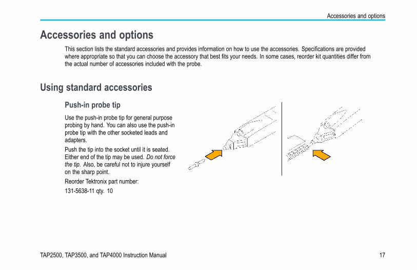
Using standard accessoriesPush-in probe tipUse the push-in probe tip for general purposeprobing by hand. You can also use the push-inprobe tip with the other socketed leads andadapters.Push the tip into the socket until it is seated.Either end of the tip may be used. Do not forcethe tip. Also, be careful not to injure yourselfon the sharp point.Reorder Tektronix part number:131-5638-11 qty. 10
TAP2500, TAP3500, and TAP4000 Instruction Manual 17
Accessories and options
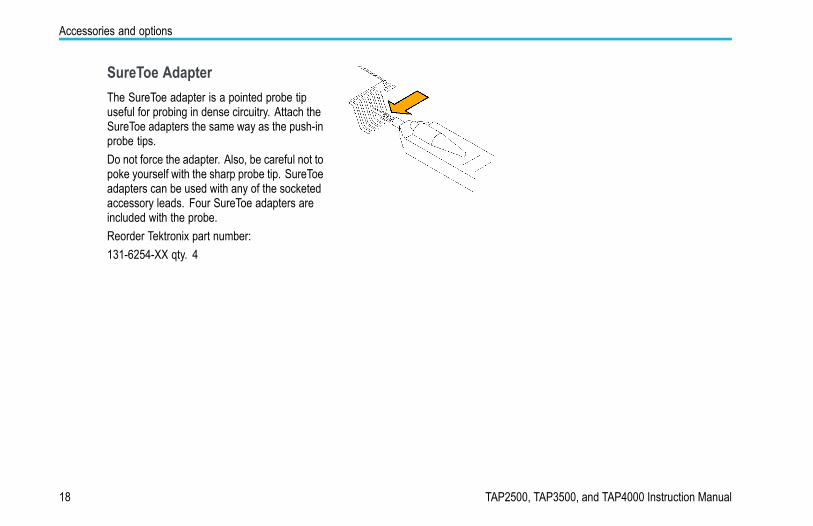
SureToe AdapterThe SureToe adapter is a pointed probe tipuseful for probing in dense circuitry. Attach theSureToe adapters the same way as the push-inprobe tips.Do not force the adapter. Also, be careful not topoke yourself with the sharp probe tip. SureToeadapters can be used with any of the socketedaccessory leads. Four SureToe adapters areincluded with the probe.Reorder Tektronix part number:131-6254-XX qty. 4
18 TAP2500, TAP3500, and TAP4000 Instruction Manual
Accessories and options
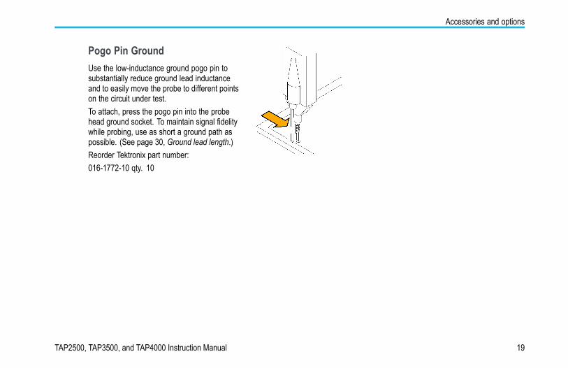
Pogo Pin GroundUse the low-inductance ground pogo pin tosubstantially reduce ground lead inductanceand to easily move the probe to different pointson the circuit under test.To attach, press the pogo pin into the probehead ground socket. To maintain signal fidelitywhile probing, use as short a ground path aspossible. (See page 30, Ground lead length.)Reorder Tektronix part number:016-1772-10 qty. 10
TAP2500, TAP3500, and TAP4000 Instruction Manual 19
Accessories and options
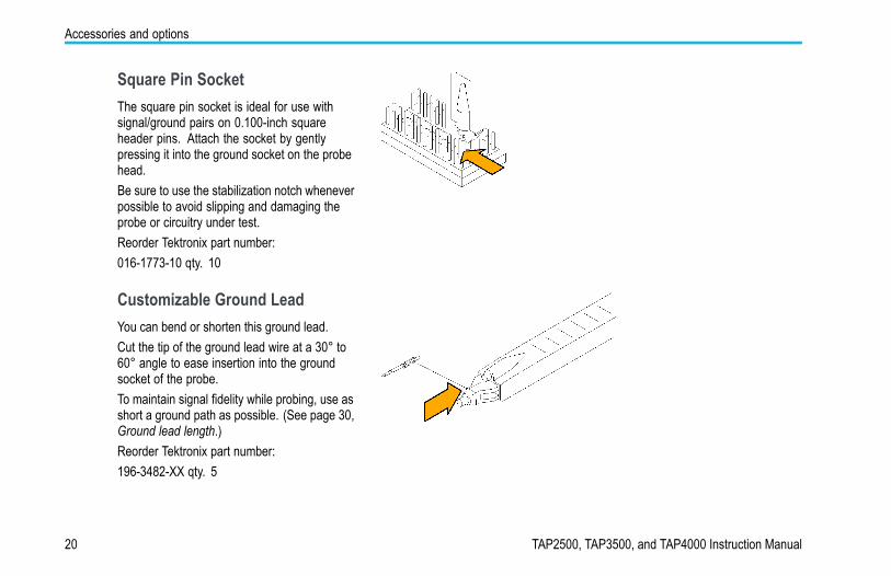
Square Pin SocketThe square pin socket is ideal for use withsignal/ground pairs on 0.100-inch squareheader pins. Attach the socket by gentlypressing it into the ground socket on the probehead.Be sure to use the stabilization notch wheneverpossible to avoid slipping and damaging theprobe or circuitry under test.Reorder Tektronix part number:016-1773-10 qty. 10
Customizable Ground LeadYou can bend or shorten this ground lead.Cut the tip of the ground lead wire at a 30° to60° angle to ease insertion into the groundsocket of the probe.To maintain signal fidelity while probing, use asshort a ground path as possible. (See page 30,Ground lead length.)Reorder Tektronix part number:196-3482-XX qty. 5
20 TAP2500, TAP3500, and TAP4000 Instruction Manual

Accessories and options
Right-Angle AdapterUse the right-angle adapter for low-profileprobing of 0.025-inch square pins. Theright-angle adapter allows the probe to lie flatagainst a circuit board, enabling you to probein tight areas such as between circuit cards.The right-angle adapter can be used directlywith the probe head, or attached to the Y-leadadapter or ground leads.Attach the right-angle adapter the same way asthe push-in probe tip.Reorder Tektronix part number:016-1774-XX qty. 10
TAP2500, TAP3500, and TAP4000 Instruction Manual 21
Accessories and options
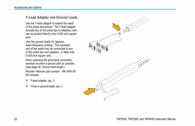
Y-Lead Adapter and Ground LeadsUse the Y-lead adapter to extend the reachof the probe and ground. The Y-lead adapteraccepts any of the probe tips or adapters, andcan be pushed directly onto 0.025 inch squarepins.Use the ground leads for general,lower-frequency probing. The socketedend of the leads may be connected to anyof the probe tips and adapters, or fitted onto0.025-inch square pins.When selecting the grounding connection,maintain as short a ground path as possible.(See page 30, Ground lead length.)Reorder Tektronix part number: 196-3456-XXKit includes:
Y-lead adapter, qty. 2
Three-in ground leads, qty. 3
22 TAP2500, TAP3500, and TAP4000 Instruction Manual
Accessories and options
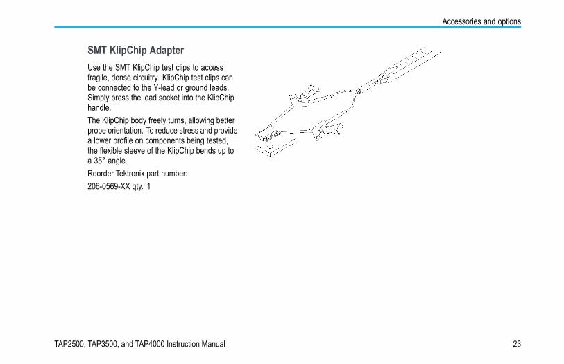
SMT KlipChip AdapterUse the SMT KlipChip test clips to accessfragile, dense circuitry. KlipChip test clips canbe connected to the Y-lead or ground leads.Simply press the lead socket into the KlipChiphandle.The KlipChip body freely turns, allowing betterprobe orientation. To reduce stress and providea lower profile on components being tested,the flexible sleeve of the KlipChip bends up toa 35° angle.Reorder Tektronix part number:206-0569-XX qty. 1
TAP2500, TAP3500, and TAP4000 Instruction Manual 23
Accessories and options
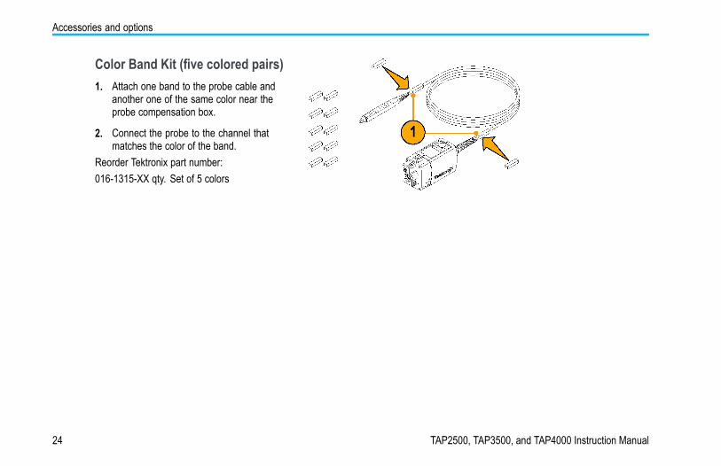
Color Band Kit (five colored pairs)1. Attach one band to the probe cable and
another one of the same color near theprobe compensation box.
2. Connect the probe to the channel thatmatches the color of the band.
Reorder Tektronix part number:016-1315-XX qty. Set of 5 colors
24 TAP2500, TAP3500, and TAP4000 Instruction Manual
Accessories and options
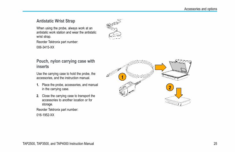
Antistatic Wrist StrapWhen using the probe, always work at anantistatic work station and wear the antistaticwrist strap.Reorder Tektronix part number:006-3415-XX
Pouch, nylon carrying case withinsertsUse the carrying case to hold the probe, theaccessories, and the instruction manual.
1. Place the probe, accessories, and manualin the carrying case.
2. Close the carrying case to transport theaccessories to another location or forstorage.
Reorder Tektronix part number:016-1952-XX
TAP2500, TAP3500, and TAP4000 Instruction Manual 25
Accessories and options
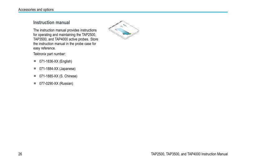
Instruction manualThe instruction manual provides instructionsfor operating and maintaining the TAP2500,TAP3500, and TAP4000 active probes. Storethe instruction manual in the probe case foreasy reference.Tektronix part number:
071-1836-XX (English)
071-1884-XX (Japanese)
071-1885-XX (S. Chinese)
077-0290-XX (Russian)
26 TAP2500, TAP3500, and TAP4000 Instruction Manual
Accessories and options
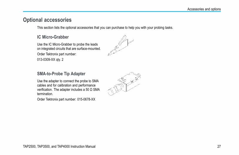
Optional accessoriesThis section lists the optional accessories that you can purchase to help you with your probing tasks.
IC Micro-GrabberUse the IC Micro-Grabber to probe the leadson integrated circuits that are surface-mounted.Order Tektronix part number:013-0309-XX qty. 2
SMA-to-Probe Tip AdapterUse the adapter to connect the probe to SMAcables and for calibration and performanceverification. The adapter includes a 50 Ω SMAtermination.Order Tektronix part number: 015-0678-XX
TAP2500, TAP3500, and TAP4000 Instruction Manual 27

Accessories and options
TekVPI Calibration FixtureThe calibration fixture is required to do aperformance verification on the probe. Itprovides an SMA connector in the probe signalpath for internal probe measurements.Order Tektronix part number: 067-1701-XX
28 TAP2500, TAP3500, and TAP4000 Instruction Manual

Accessories and options
OptionsService Options
Option CA1. Provides coverage for a single Calibration Event
Option C3. Calibration Service 3 years
Option C5. Calibration Service 5 years
Option D1. Calibration Data Report
Option D3. Calibration Data Report, 3 years (with Option C3)
Option D5. Calibration Data Report, 5 years (with Option C5)
Option R3. Repair Service 3 years
Option R5. Repair Service 5 years
Manual OptionsOption L0. English language Instruction Manual
Option L5. Japanese language Instruction Manual
Option L7. Simplified Chinese language Instruction Manual
TAP2500, TAP3500, and TAP4000 Instruction Manual 29
Probing principles
Probing principlesFollow these helpful hints to make probing easier and noise free.
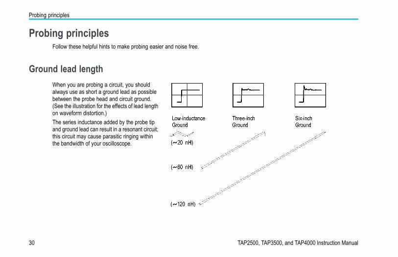
Ground lead lengthWhen you are probing a circuit, you shouldalways use as short a ground lead as possiblebetween the probe head and circuit ground.(See the illustration for the effects of lead lengthon waveform distortion.)The series inductance added by the probe tipand ground lead can result in a resonant circuit;this circuit may cause parasitic ringing withinthe bandwidth of your oscilloscope.
30 TAP2500, TAP3500, and TAP4000 Instruction Manual

Ground lead inductance
Ground lead inductanceWhen you touch your probe tip to a circuit element, you are introducing a new resistance, capacitance, and inductance into thecircuit.
You can determine if ground lead effects maybe a problem in your application if you knowthe self-inductance (L) and capacitance (C)of your probe and ground lead. Calculate theapproximate resonant frequency (f0) at whichthis parasitic circuit will resonate with thefollowing formula:The equation shows that reducing the groundlead inductance will raise the resonantfrequency. If your measurements are affectedby ringing, your goal is to lower the inductanceof your ground path until the resulting resonantfrequency is well above the frequency of yourmeasurements.The low-inductance ground contacts describedin Accessories can help you reduce theeffects of ground lead inductance on yourmeasurements.
TAP2500, TAP3500, and TAP4000 Instruction Manual 31
Low-inductance grounding
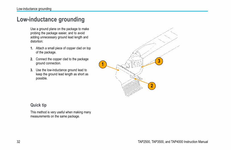
Low-inductance groundingUse a ground plane on the package to makeprobing the package easier, and to avoidadding unnecessary ground lead length anddistortion:
1. Attach a small piece of copper clad on topof the package.
2. Connect the copper clad to the packageground connection.
3. Use the low-inductance ground lead tokeep the ground lead length as short aspossible.
Quick tipThis method is very useful when making manymeasurements on the same package.
32 TAP2500, TAP3500, and TAP4000 Instruction Manual
SureFoot™ Grounding
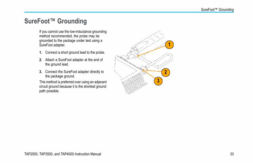
SureFoot™ GroundingIf you cannot use the low-inductance groundingmethod recommended, the probe may begrounded to the package under test using aSureFoot adapter.
1. Connect a short ground lead to the probe.
2. Attach a SureFoot adapter at the end ofthe ground lead.
3. Connect the SureFoot adapter directly tothe package ground.
This method is preferred over using an adjacentcircuit ground because it is the shortest groundpath possible.
TAP2500, TAP3500, and TAP4000 Instruction Manual 33
Probe tip test points
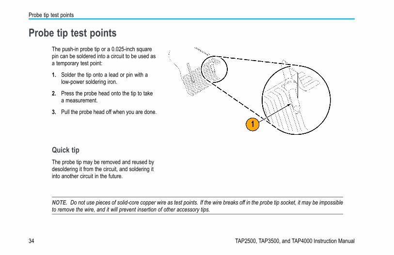
Probe tip test pointsThe push-in probe tip or a 0.025-inch squarepin can be soldered into a circuit to be used asa temporary test point:
1. Solder the tip onto a lead or pin with alow-power soldering iron.
2. Press the probe head onto the tip to takea measurement.
3. Pull the probe head off when you are done.
Quick tipThe probe tip may be removed and reused bydesoldering it from the circuit, and soldering itinto another circuit in the future.
NOTE. Do not use pieces of solid-core copper wire as test points. If the wire breaks off in the probe tip socket, it may be impossibleto remove the wire, and it will prevent insertion of other accessory tips.
34 TAP2500, TAP3500, and TAP4000 Instruction Manual
Probe tip stabilization
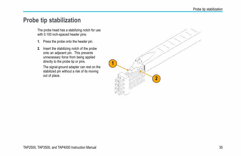
Probe tip stabilizationThe probe head has a stabilizing notch for usewith 0.100 inch-spaced header pins:
1. Press the probe onto the header pin.
2. Insert the stabilizing notch of the probeonto an adjacent pin. This preventsunnecessary force from being applieddirectly to the probe tip or pins.The signal-ground adapter can rest on thestabilized pin without a risk of its movingout of place.
TAP2500, TAP3500, and TAP4000 Instruction Manual 35
Specifications
SpecificationsThe specifications are valid under the following conditions:
The probe has been calibrated at an ambient temperature of 23 °C ±5 °C.
The probe is connected to a host instrument with an input impedance of 50 Ω .
The probe and oscilloscope must have a warm-up period of at least 20 minutes and be in an environment that does notexceed the limits described. (See Table 1.)
The Signal Path Compensation (SPC) has been run on the oscilloscope before testing the probe specifications.
Specifications for the TAP2500, TAP3500, and TAP4000 active probes fall into three categories: warranted, typical, and nominalcharacteristics.
36 TAP2500, TAP3500, and TAP4000 Instruction Manual
Specifications
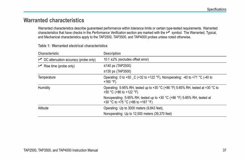
Warranted characteristicsWarranted characteristics describe guaranteed performance within tolerance limits or certain type-tested requirements. Warrantedcharacteristics that have checks in the Performance Verification section are marked with the symbol. The Warranted, Typical,and Mechanical characteristics apply to the TAP2500, TAP3500, and TAP4000 probes unless noted otherwise.
Table 1: Warranted electrical characteristics
Characteristic DescriptionDC attenuation accuracy (probe only) 10:1 ±2% (excludes offset error)Rise time (probe only) ≤140 ps (TAP2500)
≤130 ps (TAP3500)Temperature Operating: 0 to +50 _C (+32 to +122 °F), Nonoperating: -40 to +71 °C (-40 to
+160 °F)Humidity Operating: 5-95% RH, tested up to +30 °C (+86 °F) 5-85% RH, tested at +30 °C to
+50 °C (+86 to +122 °F)Nonoperating: 5-95% RH, tested up to +30 °C (+86 °F) 5-85% RH, tested at+30 °C to +75 °C (+86 to +167 °F)
Altitude Operating: Up to 3000 meters (9,843 feet),Nonoperating: Up to 12,000 meters (39,370 feet)
TAP2500, TAP3500, and TAP4000 Instruction Manual 37
Specifications
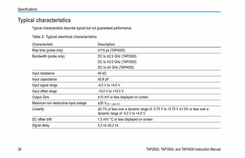
Typical characteristicsTypical characteristics describe typical but not guaranteed performance.
Table 2: Typical electrical characteristics
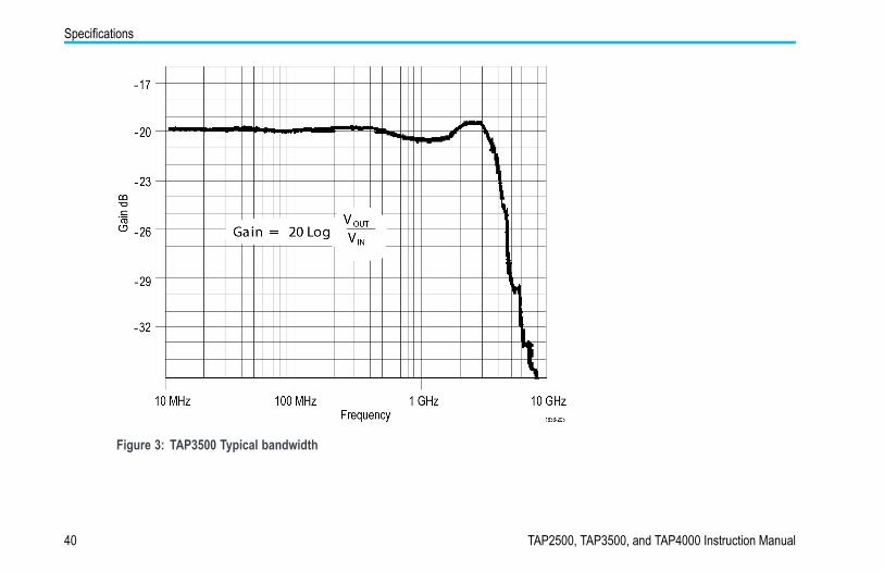
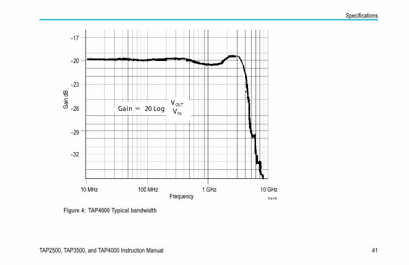
Characteristic DescriptionRise time (probe only) ≤115 ps (TAP4000)Bandwidth (probe only) DC to ≥2.5 GHz (TAP2500)
DC to ≥3.5 GHz (TAP3500)DC to ≥4 GHz (TAP4000)
Input resistance 40 kΩInput capacitance ≤0.8 pFInput signal range -4.0 V to +4.0 VInput offset range -10.0 V to +10.0 VOutput Zero ±10 mV or less displayed on screenMaximum non destructive input voltage ±30 V(DC + peak AC)
Linearity ±0.1% or less over a dynamic range of -3.75 V to +3.75 V ±1.0% or less over adynamic range of -4.0 V to +4.0 V.
DC offset drift 1.5 mV/ °C or less displayed on screenSignal delay 5.3 ns ±0.2 ns
38 TAP2500, TAP3500, and TAP4000 Instruction Manual
Specifications
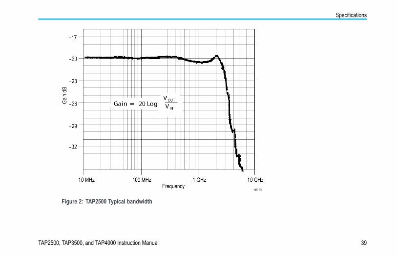
Figure 2: TAP2500 Typical bandwidth
TAP2500, TAP3500, and TAP4000 Instruction Manual 39
Specifications
Figure 3: TAP3500 Typical bandwidth
40 TAP2500, TAP3500, and TAP4000 Instruction Manual
Specifications
Figure 4: TAP4000 Typical bandwidth
TAP2500, TAP3500, and TAP4000 Instruction Manual 41
Specifications
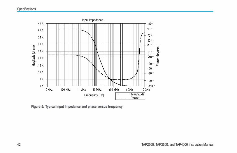
Figure 5: Typical input impedance and phase versus frequency
42 TAP2500, TAP3500, and TAP4000 Instruction Manual
Specifications
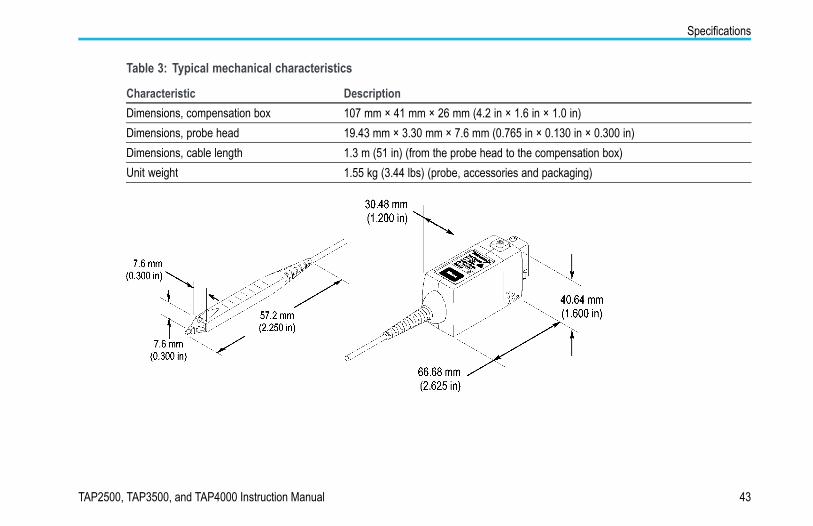
Table 3: Typical mechanical characteristics
Characteristic DescriptionDimensions, compensation box 107 mm × 41 mm × 26 mm (4.2 in × 1.6 in × 1.0 in)Dimensions, probe head 19.43 mm × 3.30 mm × 7.6 mm (0.765 in × 0.130 in × 0.300 in)Dimensions, cable length 1.3 m (51 in) (from the probe head to the compensation box)Unit weight 1.55 kg (3.44 lbs) (probe, accessories and packaging)
TAP2500, TAP3500, and TAP4000 Instruction Manual 43
Specifications
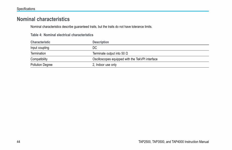
Nominal characteristicsNominal characteristics describe guaranteed traits, but the traits do not have tolerance limits.
Table 4: Nominal electrical characteristics
Characteristic DescriptionInput coupling DCTermination Terminate output into 50 ΩCompatibility Oscilloscopes equipped with the TekVPI interfacePollution Degree 2, Indoor use only
44 TAP2500, TAP3500, and TAP4000 Instruction Manual
Performance verification
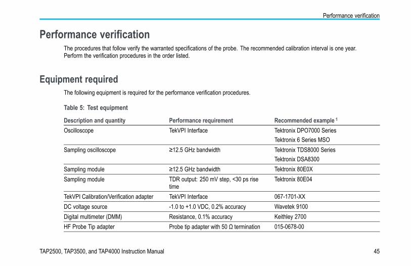
Performance verificationThe procedures that follow verify the warranted specifications of the probe. The recommended calibration interval is one year.Perform the verification procedures in the order listed.
Equipment requiredThe following equipment is required for the performance verification procedures.
Table 5: Test equipment
Description and quantity Performance requirement Recommended example 1
Oscilloscope TekVPI Interface Tektronix DPO7000 SeriesTektronix 6 Series MSO
Sampling oscilloscope ≥12.5 GHz bandwidth Tektronix TDS8000 SeriesTektronix DSA8300
Sampling module ≥12.5 GHz bandwidth Tektronix 80E0XSampling module TDR output: 250 mV step, <30 ps rise
timeTektronix 80E04
TekVPI Calibration/Verification adapter TekVPI Interface 067-1701-XXDC voltage source -1.0 to +1.0 VDC, 0.2% accuracy Wavetek 9100Digital multimeter (DMM) Resistance, 0.1% accuracy Keithley 2700HF Probe Tip adapter Probe tip adapter with 50 Ω termination 015-0678-00
TAP2500, TAP3500, and TAP4000 Instruction Manual 45

Performance verification
Table 5: Test equipment (cont.)
Description and quantity Performance requirement Recommended example 1
SMA M-to-BNC F adapter SMA male-to-BNC female 015-0554-00BNC-to-dual banana adapter (2) 103-0090-00BNC cable 50 Ω , 0.76 m (30 in) length 012-0117-00SMA cable (2) Male-to-Male SMA cable 012-0649-00Precision termination 50 Ω , 0.1%, 0.5 W 011-0129-00Y-Lead adapter 0.25-in square pins for probe tip
connections196-3457-xx 2
SMT KlipChip adapters (2) 0.25-in square pins-to-mini clips 206-0569-xx 2
SMA torque wrench 5/16-in, 7 in-lb.SMA adapter wrench 7/32-in1 Nine-digit part numbers (xxx-xxxx-xx) are Tektronix part numbers.2 Standard accessories included with the probe.
46 TAP2500, TAP3500, and TAP4000 Instruction Manual
Performance verification
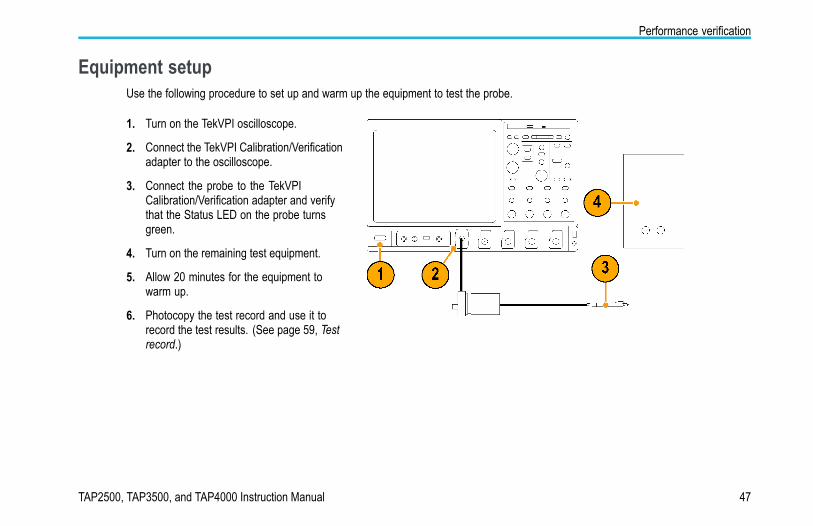
Equipment setupUse the following procedure to set up and warm up the equipment to test the probe.
1. Turn on the TekVPI oscilloscope.
2. Connect the TekVPI Calibration/Verificationadapter to the oscilloscope.
3. Connect the probe to the TekVPICalibration/Verification adapter and verifythat the Status LED on the probe turnsgreen.
4. Turn on the remaining test equipment.
5. Allow 20 minutes for the equipment towarm up.
6. Photocopy the test record and use it torecord the test results. (See page 59, Testrecord.)
TAP2500, TAP3500, and TAP4000 Instruction Manual 47
Performance verification
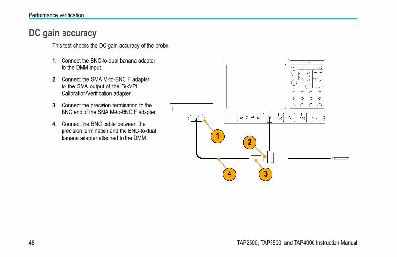
DC gain accuracyThis test checks the DC gain accuracy of the probe.
1. Connect the BNC-to-dual banana adapterto the DMM input.
2. Connect the SMA M-to-BNC F adapterto the SMA output of the TekVPICalibration/Verification adapter.
3. Connect the precision termination to theBNC end of the SMA M-to-BNC F adapter.
4. Connect the BNC cable between theprecision termination and the BNC-to-dualbanana adapter attached to the DMM.
48 TAP2500, TAP3500, and TAP4000 Instruction Manual
Performance verification
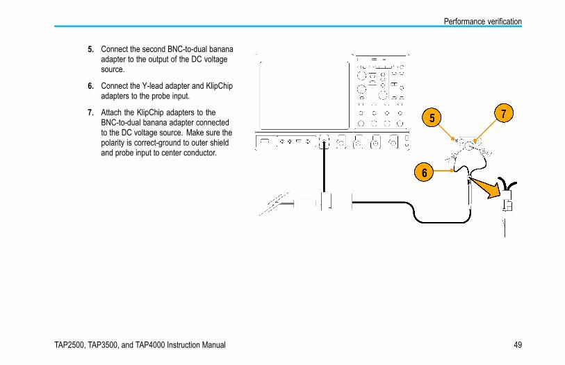
5. Connect the second BNC-to-dual bananaadapter to the output of the DC voltagesource.
6. Connect the Y-lead adapter and KlipChipadapters to the probe input.
7. Attach the KlipChip adapters to theBNC-to-dual banana adapter connectedto the DC voltage source. Make sure thepolarity is correct-ground to outer shieldand probe input to center conductor.
TAP2500, TAP3500, and TAP4000 Instruction Manual 49
Performance verification
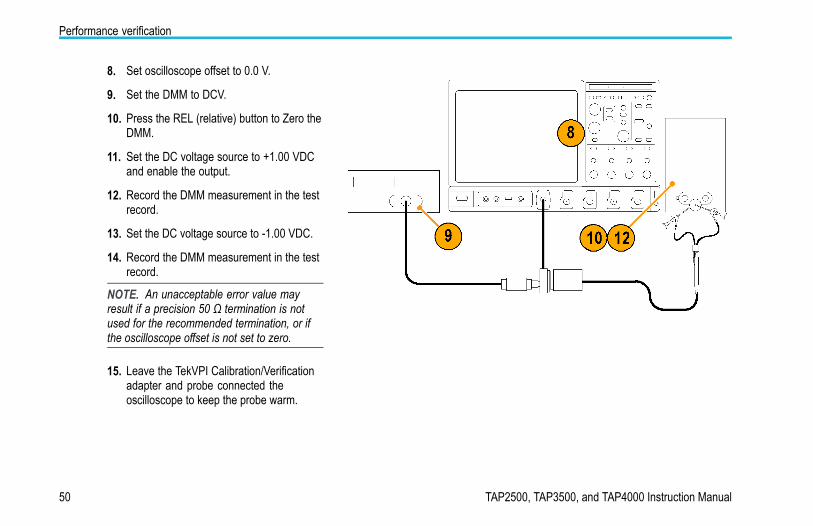
8. Set oscilloscope offset to 0.0 V.
9. Set the DMM to DCV.
10. Press the REL (relative) button to Zero theDMM.
11. Set the DC voltage source to +1.00 VDCand enable the output.
12. Record the DMM measurement in the testrecord.
13. Set the DC voltage source to -1.00 VDC.
14. Record the DMM measurement in the testrecord.
NOTE. An unacceptable error value mayresult if a precision 50 Ω termination is notused for the recommended termination, or ifthe oscilloscope offset is not set to zero.
15. Leave the TekVPI Calibration/Verificationadapter and probe connected theoscilloscope to keep the probe warm.
50 TAP2500, TAP3500, and TAP4000 Instruction Manual
Performance verification
Rise timeThis procedure verifies that the probe meets the rise time specification. Two rise times are measured; the test system alone, andthen the test system with the probe included. The probe rise time is calculated using the two measurements.
This test uses the TDR function of the 80E04 sampling head as a fast rise time signal source. A second 80E0X sampling headis used to take the measurements. Although the following procedure assigns the TDR and measurement functions to specificoscilloscope channels, any channels can be used. However, the TDR function is only available on 80E04 sampling heads.
CAUTION. To prevent damage, use care when working with SMA connectors: support equipment to avoid mechanical strain onthe connectors, and when tightening connections, use a torque wrench to 7.5 in-lbs.
TAP2500, TAP3500, and TAP4000 Instruction Manual 51
Performance verification
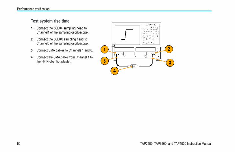
Test system rise time1. Connect the 80E04 sampling head to
Channel1 of the sampling oscilloscope.
2. Connect the 80E0X sampling head toChannel8 of the sampling oscilloscope.
3. Connect SMA cables to Channels 1 and 8.
4. Connect the SMA cable from Channel 1 tothe HF Probe Tip adapter.
52 TAP2500, TAP3500, and TAP4000 Instruction Manual
Performance verification
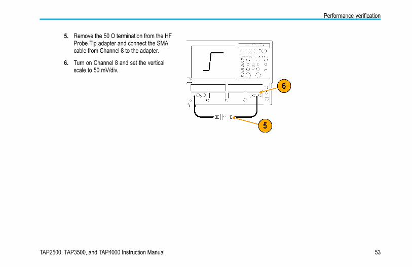
5. Remove the 50 Ω termination from the HFProbe Tip adapter and connect the SMAcable from Channel 8 to the adapter.
6. Turn on Channel 8 and set the verticalscale to 50 mV/div.
TAP2500, TAP3500, and TAP4000 Instruction Manual 53
Performance verification
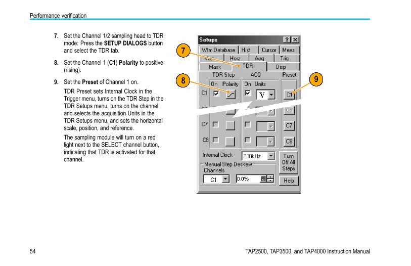
7. Set the Channel 1/2 sampling head to TDRmode: Press the SETUP DIALOGS buttonand select the TDR tab.
8. Set the Channel 1 (C1) Polarity to positive(rising).
9. Set the Preset of Channel 1 on.TDR Preset sets Internal Clock in theTrigger menu, turns on the TDR Step in theTDR Setups menu, turns on the channeland selects the acquisition Units in theTDR Setups menu, and sets the horizontalscale, position, and reference.The sampling module will turn on a redlight next to the SELECT channel button,indicating that TDR is activated for thatchannel.
54 TAP2500, TAP3500, and TAP4000 Instruction Manual
Performance verification
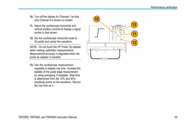
10. Turn off the display for Channel 1 so thatonly Channel 8 is shown on screen.
11. Adjust the oscilloscope horizontal andvertical position controls to display a signalsimilar to that shown.
12. Set the oscilloscope horizontal scale to50 ps/div and center the waveform.
NOTE. Do not touch the HF Probe Tip adapterwhen making calibration measurements.Measurement accuracy is degraded when theprobe tip adapter is handled.
13. Use the oscilloscope measurementcapability to display rise time. Increase thestability of the pulse edge measurementby using averaging, if available. Rise timeis determined from the 10% and 90%amplitude points on the waveform. Recordthe rise time as ts .
TAP2500, TAP3500, and TAP4000 Instruction Manual 55
Performance verification
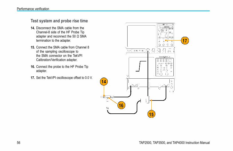
Test system and probe rise time14. Disconnect the SMA cable from the
Channel-8 side of the HF Probe Tipadapter and reconnect the 50 Ω SMAtermination to the adapter.
15. Connect the SMA cable from Channel 8of the sampling oscilloscope tothe SMA connector on the TekVPICalibration/Verification adapter.
16. Connect the probe to the HF Probe Tipadapter.
17. Set the TekVPI oscilloscope offset to 0.0 V.
56 TAP2500, TAP3500, and TAP4000 Instruction Manual
Performance verification
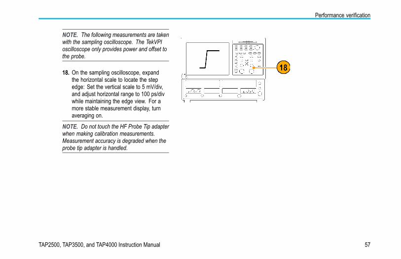
NOTE. The following measurements are takenwith the sampling oscilloscope. The TekVPIoscilloscope only provides power and offset tothe probe.
18. On the sampling oscilloscope, expandthe horizontal scale to locate the stepedge: Set the vertical scale to 5 mV/div,and adjust horizontal range to 100 ps/divwhile maintaining the edge view. For amore stable measurement display, turnaveraging on.
NOTE. Do not touch the HF Probe Tip adapterwhen making calibration measurements.Measurement accuracy is degraded when theprobe tip adapter is handled.
TAP2500, TAP3500, and TAP4000 Instruction Manual 57

Performance verification
19. Adjust the position controls on the samplingoscilloscope to display the entire leadingedge waveform.
20. Use the measurement capability of thesampling oscilloscope to display risetime: Increase the stability of the pulseedge measurement by using averaging,if available. Rise time is determined fromthe 10% and 90% amplitude points on thewaveform. Record the rise time as ts+p.
21. Using the test system rise time (ts ) thatyou measured in step 13, and the testsystem and probe rise time (ts+p ) thatyou measured in step 20, calculate theprobe-only rise time using the formulashown.
22. Check that the calculated rise time meetsthe probe specification.
23. Record the results on the test record.
Example:
58 TAP2500, TAP3500, and TAP4000 Instruction Manual
Performance verification
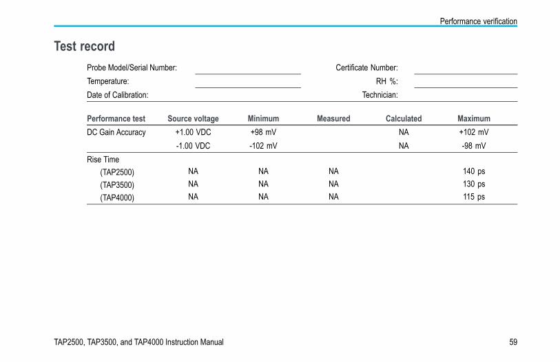
Test recordProbe Model/Serial Number: Certificate Number:Temperature: RH %:Date of Calibration: Technician:
Performance test Source voltage Minimum Measured Calculated Maximum+1.00 VDC +98 mV NA +102 mVDC Gain Accuracy-1.00 VDC -102 mV NA -98 mV
Rise Time(TAP2500)(TAP3500)(TAP4000)
NANANA
NANANA
NANANA
140 ps130 ps115 ps
TAP2500, TAP3500, and TAP4000 Instruction Manual 59
Maintenance
MaintenanceThis section contains maintenance information for your probe.
Error conditionThe TAP2500, TAP3500, and TAP4000 active probes are designed to work with all TekVPI-interface oscilloscopes and adapters.However, there may be some cases where all of the probe features may not work properly.
If the Status LED glows red during or after probe power on, an internal probe diagnostic fault exists. Disconnect and reconnect theprobe to restart the power-on diagnostic sequence. If the Status LED continues to glow red, the probe is defective, and mustbe returned to Tektronix for repair.
Replacement partsThere are no user replaceable parts within the probe. Refer to Accessories for a list of replaceable accessories for your probe.
60 TAP2500, TAP3500, and TAP4000 Instruction Manual
Maintenance
CleaningProtect the probe from adverse weather conditions. The probe is not waterproof.
CAUTION. To prevent damage to the probe, do not expose it to sprays, liquids, or solvents. Avoid getting moisture insidethe probe during exterior cleaning.
Do not use chemical cleaning agents; they may damage the probe. Avoid using chemicals that contain benzine, benzene,toluene, xylene, acetone, or similar solvents.
Clean the exterior surfaces of the probe with a dry, lint-free cloth or a soft-bristle brush. If dirt remains, use a soft cloth or swabdampened with a 75% isopropyl alcohol solution. A swab is useful for cleaning narrow spaces on the probe, use only enoughsolution to dampen the swab or cloth. Do not use abrasive compounds on any part of the probe.
TAP2500, TAP3500, and TAP4000 Instruction Manual 61

Maintenance
62 TAP2500, TAP3500, and TAP4000 Instruction Manual

Index
IndexAAccessories
optional, 27standard, 17
AutoZero, 5
CCalibration, 8Cleaning the probe, 61Connecting the probe, 2
DDC gain accuracy
performance check, 48Documentation, xi
EError condition, 60
FFeatures, 1
Functional check, 6
GGround lead
inductance, 31selecting length, 30
IIndicators, 3
LLED
Status, 3
MMaintenance, 60Menu Button, 4
OOffset, 15Options, 29
PPerformance verification, 45
equipment required, 45equipment setup, 47
Probe controls and indicators, 3Probe head, 12
RRelated documentation, xiReplacement parts, 60Rise Time
performance check, 51
SSafety Summary, vSignal path compensation, 9Specifications, 36
nominal, 44typical, 38warranted, 37
Status LED, 3, 60
TAP2500, TAP3500, and TAP4000 Instruction Manual 63

Index
TTekVPI, 2Test record, 59
64 TAP2500, TAP3500, and TAP4000 Instruction Manual