Embed Size (px)
Citation preview
ADVERTIMENT. Lʼaccés als continguts dʼaquesta tesi queda condicionat a lʼacceptació de les condicions dʼúsestablertes per la següent llicència Creative Commons: http://cat.creativecommons.org/?page_id=184
ADVERTENCIA. El acceso a los contenidos de esta tesis queda condicionado a la aceptación de las condiciones de usoestablecidas por la siguiente licencia Creative Commons: http://es.creativecommons.org/blog/licencias/
WARNING. The access to the contents of this doctoral thesis it is limited to the acceptance of the use conditions setby the following Creative Commons license: https://creativecommons.org/licenses/?lang=en
STEREOSCOPIC USER
INTERFACES Creating a Pipeline for Stereo Application Development
JUNE 3, 2016
UNIVERSITAT AUTONOMA DE BARCELONA
Bellaterra, Barcelona, Spain
Luis Diego González Zúñiga
Stereoscopic User Interfaces: Creating a Pipeline for Stereo Application
Development
Luis Diego González Zúñiga
Ph.D. Thesis Dissertation
Directed by
Jordi Carrabina, Enric Martí
PhD of Computer Science of the Universitat Autònoma de Barcelona
Engineering School. Department of Microelectronics and Electronics Systems
Bellaterra, June 2016

- A Pía. Porque siempre quisiste que fuera doctor.
i
Acknowledgements
Five years have taught me that family is first, and they are the ones that have
supported me through this process. Mami, Papito, Johanna, Paula and Ulises,
thank you. This is the result of Diego in Spain. I know you never doubted it. The
only bad thing is we were apart all this time.
Five years have taught me friends can be extended family. Maszerowska,
Yonatan, Ezgi, Roby, Blakey, Colella, Nacho, Victor, Zara, Andreita, Fernanda.
You’re constantly in my thoughts.
Five years has also taught me co-workers can be friends. To my colleagues in
UAB and in Samsung R&D UK, Marc, Shordi, Toni, Christos, Albert. Thanks for
making my days less of a routinary thing.
Finally, two special groups without which this thesis could not be accomplish.
My 3D family, Dale, Ludger, Kathleen, Lizzie, Karel, Matt, and Adrian, those
constant messages and cries for help actually resulted in something productive,
as you can read. And my PhD supervisors, Jordi and Enric, for your patience,
wisdom and intuition. This work is as much mine as yours, and I’ve enjoyed
every single second of this “good life”. Orero, you helped me get started. Ralf,
you helped me finish, and that I won’t forget.
And yet everything arrives to an end. Thanks.
ii
Abstract
The present work is PhD research done in the field of stereoscopic graphical
user interfaces. It evaluates the current state of 3D technology and the state of
the art trends in the area and translates them to software applications. The
main objective is to study how 3D depth can enhance a GUI application, by
having an aesthetic and utilitarian function. Independent of medium, our main
focus is to provide efficient tools and techniques that apply to the interface
design process to add depth to it. In this vein we work with web, desktop,
gestural technologies and perception User Experience (UX) studies with the
intention of documenting both user reactions and innovative software
implementations.
The present thesis documents our 4-year effort in the field of stereoscopic
graphical user interface. We walk through the foundations of the stereo theory
and the state of the technology. We then approach several phases of a GUI
creating pipeline: from sketching prototypes to measuring the perceived depth
effect. We built frameworks and plugins that go hand to hand with the current
technology stack and allow other developers and enthusiasts to create both
stereoscopic 3D GUIs and VR applications.
iii
Contents
Acknowledgements ...................................................................................................................... i
Abstract ............................................................................................................................................ ii
Contents .......................................................................................................................................... iii
1 Motivation ............................................................................................................................... 2
1.1 The Addressed Problem ............................................................................................ 2
1.2 Hypothesis ...................................................................................................................... 3
1.3 Objective ......................................................................................................................... 4
1.4 Methodology ................................................................................................................. 4
1.5 Structure of the dissertation .................................................................................... 4
2 The Third Dimension ........................................................................................................... 7
2.1 Understanding Projections ....................................................................................... 7
2.2 Understanding Stereoscopy ..................................................................................... 9
2.3 Depth Cues .................................................................................................................. 11
2.4 S3D Content and Related Research ................................................................... 12
2.4.1 Movies .................................................................................................................. 13
2.4.2 Videogames ........................................................................................................ 14
2.4.3 Virtual Reality ..................................................................................................... 16
2.4.4 Software ............................................................................................................... 17
2.4.5 Stereoscopic Related Hardware .................................................................. 19
2.5 Why 3D? ....................................................................................................................... 22
2.6 Summary of the chapter ......................................................................................... 23
3 Creating the tools for S3D Development ................................................................. 24
3.1 CANVAS ........................................................................................................................ 24
3.1.1 Benefits ................................................................................................................. 25
3.1.2 Challenges ........................................................................................................... 26
3.1.3 Implementation ................................................................................................. 27
3.1.4 Performance ....................................................................................................... 28
3.2 HTML5 ........................................................................................................................... 30
3.2.1 Benefits ................................................................................................................. 31
3.2.2 Challenges ........................................................................................................... 31
iv
3.3 Three.JS ......................................................................................................................... 31
3.3.1 Benefits ................................................................................................................. 32
3.3.2 Challenges ........................................................................................................... 32
3.3.3 Implementation ................................................................................................. 32
3.4 Windows Presentation Foundation .................................................................... 32
3.4.1 Benefits ................................................................................................................. 33
3.4.2 Challenges ........................................................................................................... 33
3.4.3 Implementation ................................................................................................. 34
3.4.4 Result ..................................................................................................................... 34
3.5 Unity ............................................................................................................................... 35
3.5.1 Benefits ................................................................................................................. 35
3.5.2 Implementation ................................................................................................. 36
3.5.3 Performance ....................................................................................................... 36
3.6 Summary of the chapter ......................................................................................... 36
4 Human Factors for Measurement ............................................................................... 39
4.1 Usability ........................................................................................................................ 40
4.1.1 How to Measure Usability ............................................................................. 40
4.2 Desirability ................................................................................................................... 41
4.2.1 How to Measure Desirability ........................................................................ 42
4.2.2 Why Product Reaction Cards ........................................................................ 43
4.3 Effectiveness/Efficiency ........................................................................................... 43
4.4 Eye Tracking Measurements ................................................................................. 44
4.5 Further Classification of PRC ................................................................................. 44
4.6 Summary of the chapter ......................................................................................... 51
5 Stereo Applications ........................................................................................................... 53
5.1 Pipeline for Stereo App Development .............................................................. 53
5.2 Discovering the Semantics of Depth ................................................................. 54
5.3 Types of 3D UIs .......................................................................................................... 54
5.3.1 Flat or discrete ................................................................................................... 55
5.3.2 Analog/Open Space ......................................................................................... 55
5.3.3 Limitations ........................................................................................................... 55
5.4 Case Studies ................................................................................................................ 56
v
5.4.1 Eye Tracking Preliminary Test ....................................................................... 56
5.4.2 Stereoscopic Search Engine Result Page (SERP) ................................... 58
5.4.3 Stereo 3D Memory Game .............................................................................. 66
5.4.4 Sketcheo 3D ........................................................................................................ 68
5.4.5 Stereoscopic 3D Garment Desirability Test ............................................. 72
5.4.6 Stereoscopic 3D Garment Catalog ............................................................. 77
5.5 Summary of the chapter ......................................................................................... 86
6 Conclusion ........................................................................................................................... 88
6.1 Future Work ................................................................................................................ 91
References .................................................................................................................................... 94
Appendix ..................................................................................................................................... 108
A. Author’s biography ........................................................................................................ 108
Articles ................................................................................................................................. 108
Presentations .................................................................................................................... 108
Congress Presentations ................................................................................................. 109
Posters ................................................................................................................................. 109
B. Classification of Product Reaction Cards ............................................................... 110
C. Unity CameraManagement Script ............................................................................ 112
D. Experiment Data ............................................................................................................. 114
6.1.1 D.1 Pairs Game ................................................................................................ 114
6.1.2 D.2 Garments Opinion .................................................................................. 117
6.1.3 D.3 SUS values and PRCs for Garment Catalog ................................... 119
vi
Index of Figures
Figure 1: (a): Scroller Super Mario Bros. (b): 2.5D Super Mario Galaxy. ... 8
Figure 2: (a): Perspective projection. (b): Parallel Projection. ...................... 9
Figure 3: 'fig 13' as drawn by Wheatstone on his article about stereoscopy. ..... 10
Figure 4: Picture of Gears of War 3 on a Stereoscopic TV. ......................................... 15
Figure 5: Samsung Gear VR.................................................................................................... 17
Figure 6: Red-Cyan anaglyph glasses. ................................................................................ 20
Figure 7: Side by side 3D picture taken from joshuatree3d.files.wordpress.com.
.......................................................................................................................................................... 21
Figure 8: NVIDIA's active shutter glasses. ......................................................................... 22
Figure 9: Stereo Composition on a browser with canv.3d. ......................................... 26
Figure 10: Path operations in a canvas context. ............................................................. 27
Figure 11: Stereo JS drawing script performance on desktop browsers. .............. 29
Figure 12: Stereo JS drawing script performance on mobile devices. .................... 29
Figure 13: WPF's Viewport3D camera. ............................................................................... 33
Figure 14: Stereo WPF 3D example. Log in screen. ....................................................... 35
Figure 15: S3DCamera game object properties. ............................................................. 36
Figure 16: How to define UX ................................................................................................. 39
Figure 17: Card sorting editor with Reaction cards added. ........................................ 46
Figure 18: Naming defined groups in a Card Sorting Session. ................................. 47
Figure 19: Cluster Analyser. .................................................................................................... 48
Figure 20: Stereo App Development Pipeline ................................................................. 53
Figure 21: First clip of ET test. ............................................................................................... 56
Figure 22: Second clip of ET test. Red eyes. ..................................................................... 57
Figure 23: Third clip of ET test. Environment. .................................................................. 57
Figure 24: 2D/3D AOI relative dwell time for Figure 21. ............................................. 58
Figure 25: Graphical representation of the Golden triangle and the F-shaped
pattern. .......................................................................................................................................... 59
Figure 26: Areas of interest. Indigo (Results) represents ‘result AOI’, turquoise
(Ads) ‘ads AOI’. ........................................................................................................................... 60
Figure 27: AOI Sequence charts. Each row in the Y axis represents a user. X axis
time (0-20s). Indigo color refers to (‘R’) results and turquoise to (‘A’) ads. 2D
stimulus. ........................................................................................................................................ 63
Figure 28: AOI Sequence charts. Each row in the Y axis represents a user. X axis
time (0-20s). Indigo (‘R’) results and turquoise (‘A’) ads. 3D stimulus. ................... 63
Figure 29: Heat map on 2D stimulus at 20s mark .......................................................... 65
Figure 30: Heat map on 3D stimulus at 20s mark .......................................................... 65
Figure 31: S3D Memory game .............................................................................................. 66
Figure 32: sketch UI controls ................................................................................................. 70
Figure 33: Login screen sketch made in the application. ............................................ 71
Figure 34: Skinned login screen mock-up ........................................................................ 71
vii
Figure 35: Initial Garment Stimulus ..................................................................................... 73
Figure 36: Participant profile ................................................................................................. 74
Figure 37: Word appearance by stimuli. ............................................................................ 76
Figure 38: Desirability result from PRC analysis ............................................................. 76
Figure 39: S3D Garment Stimulus ........................................................................................ 78
Figure 40: Application menu in top-bottom format ..................................................... 78
Figure 41: Garment detail page ............................................................................................ 79
Figure 42: Pop-Up message ................................................................................................... 80
Figure 43: Positioning of elements from Figure 28 in the available depth. ......... 80
Figure 44: Experiment Setting for S3D Catalog .............................................................. 82
Figure 45: 2D eye tracking heatmap of garment in overlay format. ....................... 83
Figure 46: 3D eye tracking heatmap of garment in overlay format. ....................... 84
Figure 47: 3D eye tracking heatmap of all garments in original format................ 84
Figure 48: Fixation duration average per garment. ....................................................... 85
Figure 49: Desirability results from PRC analysis ............................................................ 85
Figure 50: Stereo App Development Pipeline ................................................................. 88
Index of Tables
Table 1: All-Time box office revenue (January 2015) (International 3D &
Advanced Imaging Society, 2015). ...................................................................................... 13
Table 2: Number of available 3D games for different platforms. ............................ 15
Table 3: File size ratios for composition of image in Figure 8. .................................. 26
Table 4: Preliminary Macro Groupings............................................................................... 49
Table 5: Group classification inside macro groups. ....................................................... 50
Table 6: Dwell Time indicators in results (R) and ads (A). ........................................... 62
Table 7: Pairs game GUI statistical description ............................................................... 68
Table 8: Garment perceived attractiveness means (n=40) ......................................... 83
Table 9: Average total duration in AOI in milliseconds. .............................................. 85
viii
Acronyms
3D Third Dimension
AOI Area of interest
API Application Programming Interface
AR Augmented Reality
C# C Sharp
CGI Computer Generated Images
CSS Cascade Style Sheet
DOM Document Object Model
GIF [File type] Graphical Interchange Format
GUI Graphical User Interface
HDR High Dynamic Range
HFR High Frame Rate
HTML Hyper Text Markup Language
IDE Integrated Development Environment
JPEG/JPG [File type] Joint Photographic Experts Group
JS JavaScript
KPI Key Performance Indicator
MPO [File type] Multi Picture Object
PNG [File type] Portable Network Graphic
S3D Stereoscopic 3D
SERP Search Engine Result Page
SUM Single Usability Metric
SUMI Software Usability Measurement Inventory
SUPR-Q Standardized User Experience Percentile Rank Questionnaire
SUS System Usability Scale
SVG Scalable Vector Graphics
UCD User Centered Design
UHD Ultra High Definition
VOD Video On Demand
VR Virtual Reality
WCF Windows Communication Foundation
WPF Windows Presentation Foundation
WWF Windows Workflow Foundation
X3D Extensible 3D
XAML Extensible Application Mark-up Language

1
Section Zero
The reason behind this work This initial section lays the foundation of the present work. Motivation,
addressed problem, hypothesis, methodology and structure of the current work
reside here. This chapter serves as an introduction and a guide to understand
the present work.
2
1 Motivation
I am a visual person. Starting with the way I remember things and make
associations, my memory and way of learning have always been visual. With
this, as a computer engineer, I have always been very interested in exploring
user interfaces and the small details that make them great –or not so great.
With the re-emergence of 3D in movies, I was exposed as a consumer to a new
(new for me, at least) visual stimuli that was interesting enough to keep an eye
on. I had never thought of the applications of this kind of language to things
other than the ones one is exposed as a customer. Nevertheless, with a
previous incursion into the field of stereoscopic images -to create subtitles for
3D movies in a past master degree- at the Autonomous University of Barcelona,
I started looking into the idea of stereoscopic 3D (S3D) applications.
I learnt that while movies and games were areas that have had a big boost from
different angles towards S3D, applications were being left behind. Almost trying
to emulate the same mistake the industry was making with the current phase
movies are right now, 2D techniques were being applied to this new medium
and it was generating issues. These issues could have been avoided if they were
tackled from the start for what they are: a new and different kind of problem.
Stereoscopic interfaces do exist. I am not saying the contrary, but their focus is
shifted to artificial environments which again do not apply to the specific case
of more “traditional” applications.
I add the fact that in this subject there is a mix of interaction, perception and
other areas related to humanities. Leaving aside the technical part managing
offsets, parallaxes, automation of pipelines and real-time rendering; we can say
we are doing digital stereoscopy applied to user interfaces.
1.1 The Addressed Problem
The addressed issue resides in the lack of depth in current graphical user
interfaces. While this is software related, we must point out that it is correlated
to the current state of consumer hardware and use of applications. The average
consumer does not own stereo capable devices nor content.
One can argue that there are no services that require stereo 3D depth. The rise
of mobile platforms and smart environments, where multimedia takes a front
and center approach in form of services and applications, makes the
3
exploration of depth much more relevant. In summary, we address stereoscopic
depth in graphical user interfaces.
1.2 Hypothesis
For reference, the original hypothesis that we used to start our research was the
following:
Stereoscopic 3D will enhance applications and bring a new
paradigm to UI development.
It was broad. It was open. Nonetheless we were expecting 3D to take its course.
The concept of “enhancing” had to be defined; and the fact that a new
paradigm would appear due to 3D, morphed to completely different scenario
when VR and AR became a trend. When we started this work the environment
regarding stereoscopic 3D was very different. We were thinking that
stereoscopic 3D could enhance (desktop-like) applications and could bring a
new paradigm to user interface development. These changes would be studied
to document semantic information given to objects placed in different
parallaxes (z-depth) and their relation with navigation and selection processes
in applications. The hierarchical relationship (created with depth differences)
between objects would also be studied and its relation with the different uses
of 2D images over depth maps and stereoscopic data. This would be done to
prove that depth enabled user interfaces should not be bound only to virtual
and augmented environments.
While this statement is still valid today, four years after conceiving it, the means
for display and interaction have evolved significantly. Stereo has matured, and
technology and consumers have had their say on 3Ds current position. We
found ourselves more and more exploring different means of visualization
other than traditional monitors, testing projection and virtual reality and
interacting with gestures.
Therefore, our hypotheses are a specialization of our initial idea.
A pipeline can be created with existing developer technologies to
create 3D applications.
Stereoscopic 3D can aid tasks in applications.
Stereoscopic 3D can improve desirability in applications.
These hypotheses derive from our initial idea, while defining what “enhance”
means for us and allow us to create a pipeline for stereoscopic development. All
concepts and ideas are exposed and clearly defined along the present work.

4
1.3 Objective
Upon starting the current work, the main objective of this work is the creation
and evaluation of stereoscopic graphical user interface content by providing a
set of tools and criteria using state-of-the-art software technologies.
The scenarios might range from media subtitling to user interfaces present in
desktop applications and surfaces, but a consistent way of planning, creating
and evaluating is presented.
Stereoscopic data, images and depth provide additional means of interaction
that will be used to study the display of content (layout).
We will study depth cues and their effects in these selection and layout
schemes that we find, in order to propose a framework and reference parallax
values for working with 3D interfaces.
1.4 Methodology
The main methodology consists in prototyping and user testing. These
prototypes and tests respond to the variables that will be studied to
determinate the semantic relevance assigned to parallax values.
This work can be described in several stages that behave in an iterative cycle:
1. Initial knowledge body construction.
a. Study of depth cues and hierarchical relationships and their
mapping to parallax values.
b. Evaluation of current UX patterns.
c. Training CGI skills to create prototypes.
2. Construction of prototypes.
3. User and usability testing.
Three main experiments will be developed, each one built on experiences and
knowledge extracted from the results obtained from its predecessor. These
experiments are:
Eye tracking perception of depth (2D vs. 3D web page).
3D memory test
Measure of UX of 3D in a retailing GUI catalog.
1.5 Structure of the dissertation
The following chapters define the outline and backbone of the thesis.
5
Section One “State of the 3D world” denotes the current state of the art and
state of the technology regarding all things 3D that affect the stereoscopic
application world and related research being done in the area. This section sets
the base from which we are starting, viewed from different angles.
The Third Dimension: explores how we are able to perceive stereo 3D,
how it is being applied to different areas and why is it important in those
areas.
Creating the tools for S3D Development: presents our first contributions
to this state of the 3D world, in the form of tools tailored to create S3D
applications, a fundamental part of the stereoscopic 3D pipeline we have
envision.
Section Two “In depth Software” delves deeper into user interfaces and our
approach into introducing 3D. We establish the important parameters related
to user experience that we use to compare our applications. We also denote
how we will utilise depth in our case studies.
UX Concepts for Measurement: Denotes the UX concepts that present
importance for our studies. We focus our efforts in usability and
desirability of the software experiences we create. We specify the
existing tools and techniques that will aid us in evaluating our
applications. System Usability Scale, Product Reaction Cards and Eye
tracking are explained here. A contribution on classification of the
Product Reaction Cards is then presented.
Stereo Applications: This chapter takes a look at the defined pipeline for
stereo 3D development and specifies how we will use depth in our
examples. It also defines the types of 3D that we use, and presents our
case scenarios along with the experiments that support these
implementations of depth.
Section Three “Making sense of depth in software” analyses the data from the
experiments and presents conclusions. Also, main scientific contributions and
the created pipeline are discussed and examined. Finally, a discussion on
current and future trends on this same topic is presented, therefore closing the
thesis on how our work has contributed in these directions.
6
Section One
State of the 3D world In order to work on the area of stereoscopic 3D, we must first define and
comprehend what 3D is. We offer an explanation of the theory and physiology
behind our perception of depth. Additionally, we also need to know what exists
in the consumer world and which are the technology trends that gravitate
around stereoscopic 3D. For this, we look into the different kinds of 3D content
available in the market, hardware required to visualize stereo content, and
software components like file formats, applications, and most importantly for
us, the implementation alternatives that we have for 3D.
7
2 The Third Dimension
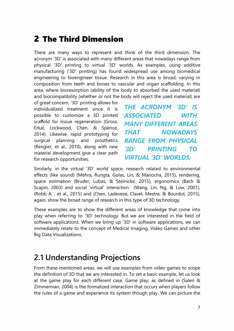
There are many ways to represent and think of the third dimension. The
acronym ‘3D’ is associated with many different areas that nowadays range from
physical ‘3D’ printing to virtual ‘3D’ worlds. As examples, using additive
manufacturing (‘3D’ printing) has found widespread use among biomedical
engineering to bioengineer tissue. Research in this area is broad, varying in
composition from teeth and bones to vascular and organ scaffolding. In this
area, where bioresorption (ability of the body to absorbed the used material)
and biocompatibility (whether or not the body will reject the used material) are
of great concern, ‘3D’ printing allows for
individualized treatment since it is
possible to customize a 3D printed
scaffold for tissue regeneration (Gross,
Erkal, Lockwood, Chen, & Spence,
2014). Likewise, rapid prototyping for
surgical planning and prosthetics
(Rengier, et al., 2010), along with new
material development give a clear path
for research opportunities.
Similarly, in the virtual ‘3D’ world space, research related to environmental
effects (like sound) (Mehra, Rungta, Golas, Lin, & Manocha, 2015), rendering,
space estimation (Bruder, Lubas, & Steinicke, 2015), ergonomics (Bach &
Scapin, 2003) and social ‘virtual’ interaction (Wang, Lin, Ng, & Low, 2001),
(Robb A. , et al., 2015) and (Chen, Ladeveze, Clavel, Mestre, & Bourdot, 2015),
again, show the broad range of research in this type of 3D technology.
These examples are to show the different areas of knowledge that come into
play when referring to ‘3D’ technology. But we are interested in the field of
software applications. When we bring up ‘3D’ in software applications, we can
immediately relate to the concept of Medical Imaging, Video Games and other
Big Data Visualizations.
2.1 Understanding Projections
From these mentioned areas, we will use examples from video games to scope
the definition of 3D that we are interested in. To set a basic example, let us look
at the game play for each different case. Game play, as defined in (Salen &
Zimmerman, 2004) is the formalized interaction that occurs when players follow
the rules of a game and experience its system though play. We can picture the
THE ACRONYM ‘3D’ IS
ASSOCIATED WITH
MANY DIFFERENT AREAS
THAT NOWADAYS
RANGE FROM PHYSICAL
‘3D’ PRINTING TO
VIRTUAL ‘3D’ WORLDS.
8
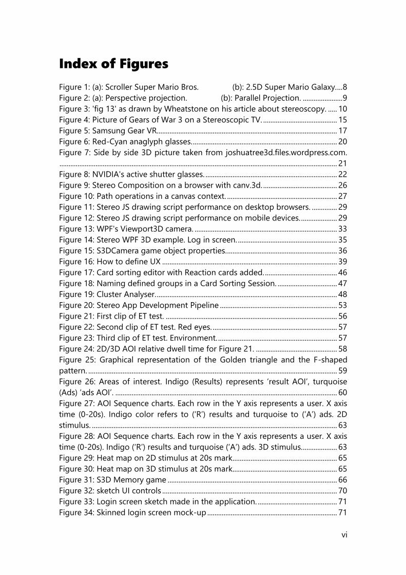
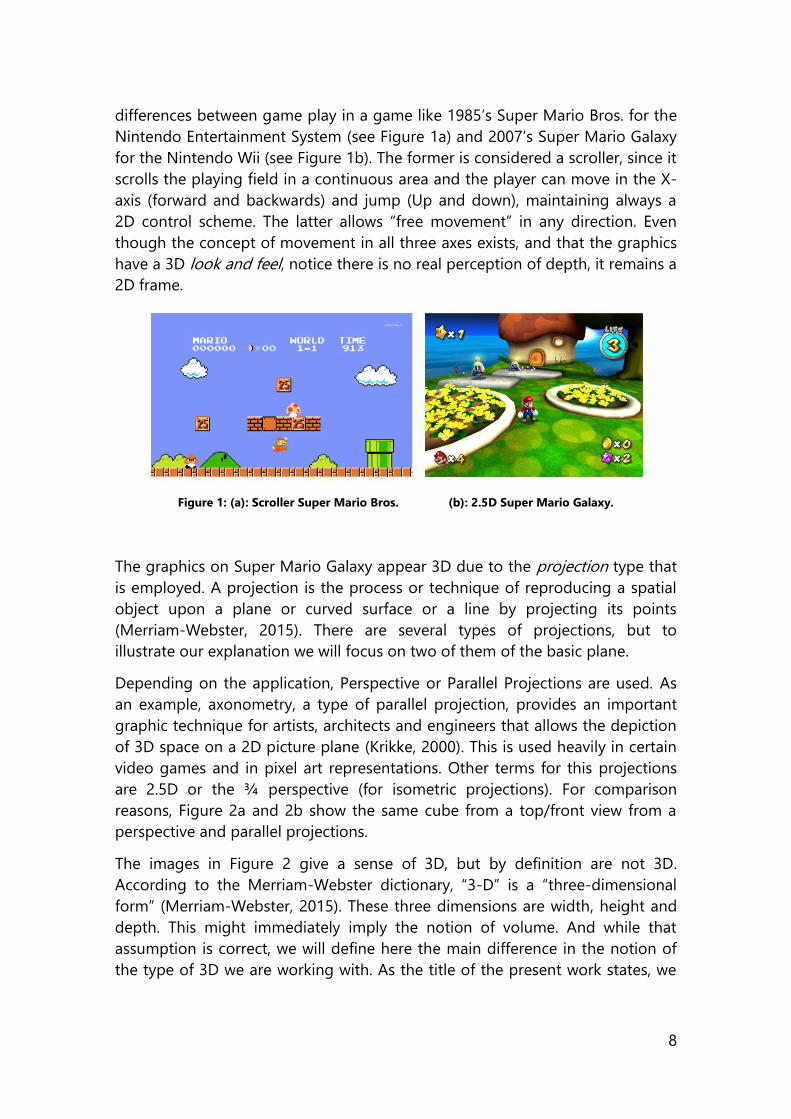
differences between game play in a game like 1985’s Super Mario Bros. for the
Nintendo Entertainment System (see Figure 1a) and 2007’s Super Mario Galaxy
for the Nintendo Wii (see Figure 1b). The former is considered a scroller, since it
scrolls the playing field in a continuous area and the player can move in the X-
axis (forward and backwards) and jump (Up and down), maintaining always a
2D control scheme. The latter allows “free movement” in any direction. Even
though the concept of movement in all three axes exists, and that the graphics
have a 3D look and feel, notice there is no real perception of depth, it remains a
2D frame.
Figure 1: (a): Scroller Super Mario Bros. (b): 2.5D Super Mario Galaxy.
The graphics on Super Mario Galaxy appear 3D due to the projection type that
is employed. A projection is the process or technique of reproducing a spatial
object upon a plane or curved surface or a line by projecting its points
(Merriam-Webster, 2015). There are several types of projections, but to
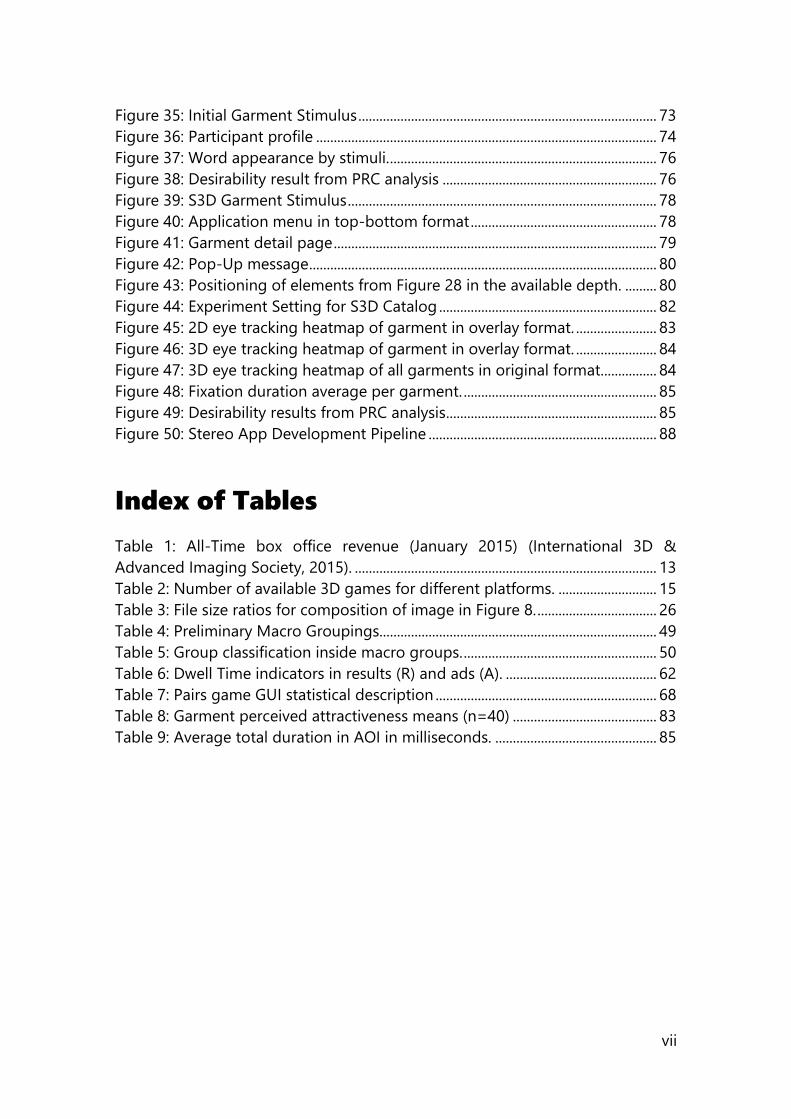
illustrate our explanation we will focus on two of them of the basic plane.
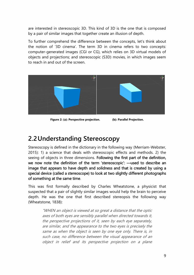
Depending on the application, Perspective or Parallel Projections are used. As
an example, axonometry, a type of parallel projection, provides an important
graphic technique for artists, architects and engineers that allows the depiction
of 3D space on a 2D picture plane (Krikke, 2000). This is used heavily in certain
video games and in pixel art representations. Other terms for this projections
are 2.5D or the ¾ perspective (for isometric projections). For comparison
reasons, Figure 2a and 2b show the same cube from a top/front view from a
perspective and parallel projections.
The images in Figure 2 give a sense of 3D, but by definition are not 3D.
According to the Merriam-Webster dictionary, “3-D” is a “three-dimensional
form” (Merriam-Webster, 2015). These three dimensions are width, height and
depth. This might immediately imply the notion of volume. And while that
assumption is correct, we will define here the main difference in the notion of
the type of 3D we are working with. As the title of the present work states, we
9
are interested in stereoscopic 3D. This kind of 3D is the one that is composed
by a pair of similar images that together create an illusion of depth.
To further comprehend the difference between the concepts, let’s think about
the notion of ‘3D cinema’. The term 3D in cinema refers to two concepts:
computer-generated images (CGI or CG), which relies on 3D virtual models of
objects and projections; and stereoscopic (S3D) movies, in which images seem
to reach in and out of the screen.
Figure 2: (a): Perspective projection. (b): Parallel Projection.
2.2 Understanding Stereoscopy
Stereoscopy is defined in the dictionary in the following way (Merriam-Webster,
2015): 1) a science that deals with stereoscopic effects and methods. 2) the
seeing of objects in three dimensions. Following the first part of the definition,
we now note the definition of the term ‘stereoscopic’: —used to describe an
image that appears to have depth and solidness and that is created by using a
special device (called a stereoscope) to look at two slightly different photographs
of something at the same time.
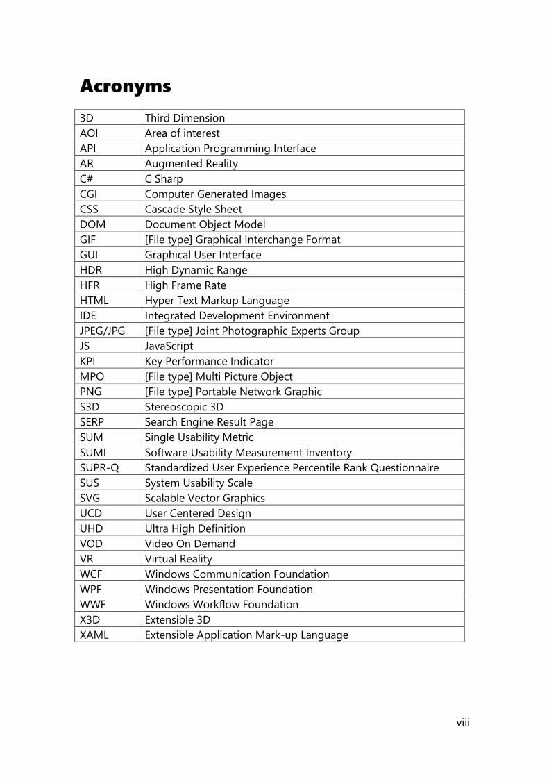
This was first formally described by Charles Wheatstone, a physicist that
suspected that a pair of slightly similar images would help the brain to perceive
depth. He was the one that first described stereopsis the following way
(Wheatstone, 1838):
“WHEN an object is viewed at so great a distance that the optic
axes of both eyes are sensibly parallel when directed towards it,
the perspective projections of it, seen by each eye separately,
are similar, and the appearance to the two eyes is precisely the
same as when the object is seen by one eye only. There is, in
such case, no difference between the visual appearance of an
object in relief and its perspective projection on a plane
10
surface; and hence pictorial representations of distant objects,
when those circumstances which would prevent or disturb the
illusion are carefully excluded, may be rendered such perfect
resemblances of the objects they are intended to represent as
to be mistaken for them; the Diorama is an instance of this. But
this similarity no longer exists when the object is placed so
near the eyes that to view it the optic axes must converge;
under these conditions a different perspective projection of it is
seen by each eye, and these perspectives are more dissimilar as
the convergence of the optic axes becomes greater. This fact
may be easily verified by placing any figure of three
dimensions, an outline cube for instance, at a moderate
distance before the eyes, and while the head is kept perfectly
steady, viewing it with each eye successively while the other is
closed. Plate XI. fig. 13. represents the two perspective
projections of a cube; b is that seen by the right eye, and a that
presented to the left eye; the figure being supposed to be
placed about seven inches immediately before the spectator.”
When we read the past quote, we notice that perspective and projections are
an important factor that create the stereoscopic image. ‘Figure 13’, cited by
Wheatstone, is shown in Figure 3.
Figure 3: 'fig 13' as drawn by Wheatstone on his article about stereoscopy.
Wheatstone refers to when the optic axes must converge. It is then when we
perceive the differences in the images caused by the point of view and the
perspective itself. He created a device that allowed him to place these slightly
different drawings that were based in perspectives of things he observed. He
called the device a “stereoscope”, and what it did was that it allowed to fuse
two flat drawings into a composition that appeared to have depth. Shortly after
came the invention of photography. Stereoscopic pictures, shown in
conjunction with the stereoscope, became a popular development, and thus,
stereo stimuli and stereo ‘hardware’ became available. This is the type of 3D
11
that we are pursuing: Stereoscopic 3D. To better understand this, we will
explore how stereoscopy works.
Due to the fact that our eyes are
horizontally separated, each one
captures a slightly different retinal
image: the one that corresponds to its
point of view. The mind works with
diverse depth cues to reconstruct depth
from what we see. Of these cues,
stereopsis is the binocular cue that
refers to the perception of depth that is
constructed based on these two points
of view. The brain fuses the left and
right image and using retinal disparity is able to extract the depth information.
Retinal disparity comes from the distance between corresponding points in
these retinal images. This implies that when focusing on an object, those points
(of fixation) will fall on corresponding parts of the retina, which denotes zero
retinal disparity. So defining the horopter (Merriam-Webster, 2015) here, any
point that does not fall within this space of corresponding retinal points will
incur in retinal disparity. If an object is in front of the defined horopter, then the
points will be crossed in disparity and objects located behind it will have
uncrossed disparity. A small region around the horopter, called Panum’s
fusional area (where the two images perceived by both eyes fuse (Puell, 2006)),
is the region where binocular single vision takes place, which means that both
images are fused into a single image in depth (Marc T.M. Lambooij, 2007).
Stereopsis is the most powerful depth cue that we possess, nonetheless, other
cues exist that work in aggregation with stereopsis to understand the world
around us. For reference, and because these concepts play an important part of
the work we have developed, I include the next section focusing on these other
monoscopic and oculomotor cues.
2.3 Depth Cues
Images formed in our retina are two dimensional. All the information regarding
distance is inferred from the image and by the visual system. This information is
gathered and reconstructed in the brain, and permits localization of objects the
same way the auditory system can map the source of a sound. Depth can be
inferred from three types of cues (Olshausen, 2015): oculomotor, visual
binocular and visual monocular:
STEREOPSIS IS THE MOST
POWERFUL DEPTH CUE
THAT WE POSSESS,
NONETHELESS, OTHER
CUES EXIST THAT WORK
IN AGGREGATION WITH
STEREOPSIS TO
UNDERSTAND THE
WORLD AROUND US.
12
Oculomotor hints include accommodation which is when the lens of the
eye changes size in order to focus an object in the retina; objects far
away from us require a low concave shape versus a major concavity
required for closer ones. Vergence is the other oculomotor prompt that
refers to the movement of the eye when focusing distant objects (that
tend to go in parallel lines) and close objects (that tend to bend to
position inwards). These cues are related to the physiological processes
of the eye.
Binocular cues consist in the horizontal disparity between slightly
different images perceived by the left and right eye. Stereopsis, as
explained before, is the process by which depth information is extracted
from the scene composed in Panum’s area. This concept must not be
confused with depth perception because we can perceive depth without
binocular vision; nonetheless, it is the most advanced state of visual
perception.
Monocular cues on the other hand can be obtained using kinetic vision,
such as occlusion, size, perspective, parallax and definition of a terrain
(Pipes, 2008). Occlusion indicates depth with superposition of objects.
Size and perspective alone can also indicate the distance of an object (if
the object is familiar and has an established concept in our brain the
process is faster). Finally, parallax is one of the most important
monoscopic cues because it relates with movement and different points
of view. Parallax is the relative position of an object’s image in a set of
pictures (Mendiburu, 2009).
All of them play an important role in the way we recognise depth, but none of
them, not even stereopsis is required to distinguish depth. Oliver Sacks has
documented the case of Sue Barry, who could navigate and live a normal life,
while being stereo-blind and not knowing it (Sacks, 2010).
With the review on the physiological process of how we perceive depth, we
now focus on the type of content we can perceive.
2.4 S3D Content and Related Research
We now know that the 3D content that we are interested in is the one that is
stereoscopic. We are going to take a look at the state of the stereoscopic
content to date, and try to extract valuable lessons we can from these different
applications of stereoscopy aided by research done in these areas.
13
2.4.1 Movies
Film is one of the areas that has enjoyed “3D” for a prolonged –combined-
period of time. It has seen it come and go every 30 years for several times now.
When we think about it, the current wave of 3D we are experiencing in theaters
nowadays was started in 2004 with the film “Polar Express” (Zemeckis, 2004).
Several films have been praised for their use of stereo 3D. For example, Avatar
(Cameron, Avatar, 2009) for its technical push of stereo. James Cameron used
composition of faraway and nearby stereo planes, achieving visuals that were
unseen at the time. Other movies followed and used 3D as part of the
storytelling process, like Gravity (Cuarón, 2013), giving a sense of imprisonment
during the capsule scenes, or Tron: Legacy (Kosinski, 2010), using S3D only
when in the virtual world.
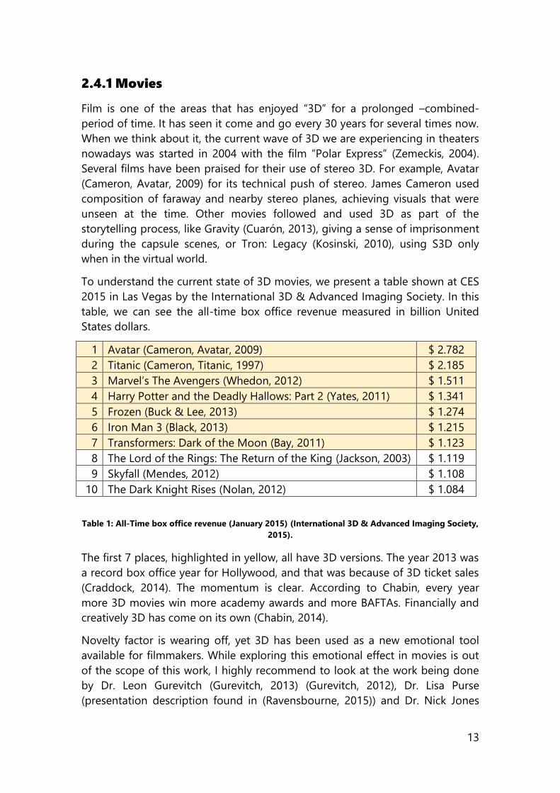
To understand the current state of 3D movies, we present a table shown at CES
2015 in Las Vegas by the International 3D & Advanced Imaging Society. In this
table, we can see the all-time box office revenue measured in billion United
States dollars.
1 Avatar (Cameron, Avatar, 2009) $ 2.782
2 Titanic (Cameron, Titanic, 1997) $ 2.185
3 Marvel’s The Avengers (Whedon, 2012) $ 1.511
4 Harry Potter and the Deadly Hallows: Part 2 (Yates, 2011) $ 1.341
5 Frozen (Buck & Lee, 2013) $ 1.274
6 Iron Man 3 (Black, 2013) $ 1.215
7 Transformers: Dark of the Moon (Bay, 2011) $ 1.123
8 The Lord of the Rings: The Return of the King (Jackson, 2003) $ 1.119
9 Skyfall (Mendes, 2012) $ 1.108
10 The Dark Knight Rises (Nolan, 2012) $ 1.084
Table 1: All-Time box office revenue (January 2015) (International 3D & Advanced Imaging Society,
2015).
The first 7 places, highlighted in yellow, all have 3D versions. The year 2013 was
a record box office year for Hollywood, and that was because of 3D ticket sales
(Craddock, 2014). The momentum is clear. According to Chabin, every year
more 3D movies win more academy awards and more BAFTAs. Financially and
creatively 3D has come on its own (Chabin, 2014).
Novelty factor is wearing off, yet 3D has been used as a new emotional tool
available for filmmakers. While exploring this emotional effect in movies is out
of the scope of this work, I highly recommend to look at the work being done
by Dr. Leon Gurevitch (Gurevitch, 2013) (Gurevitch, 2012), Dr. Lisa Purse
(presentation description found in (Ravensbourne, 2015)) and Dr. Nick Jones
14
(Jones, 2015). Directors have artistic freedom to use depth in many different
ways. For example, in Life of Pi (Lee, Life of Pi, 2012) Lee uses 3D “to make the
water become a character, to involve the audience in a way that they
experience what Pi experiences ” (Lee, 2013). In a different way, Wim Wenders
expresses that 3D “gets you close to the character and you see more into the
soul of the person” (Knight, 2015). An interesting article on the future of 3D film
technology can be found in (Bredow, 2006). Similarly, many other articles
analyse the story and current state of 3D, like (Eisenstein, 1949), (American
Cinematographer, 1953), (Lipton, 1982) and (Hayes, 1989),
I understand that many of the references cited before are very new and
respond to market behavior, but it is very important to know the frame in which
this work was developed, in order to understand the decisions that have
affected it. All these, coupled with the explosion of 3D cinema screens in China,
increasing TV size, and the availability of new technologies like auto
stereoscopic displays, HFR, HDR and UHD (International 3D & Advanced
Imaging Society, 2015), are shaping a new beginning –again- for stereoscopic
3D.
Even though the use of 3D and emotional response from users is completely an
artistic endeavour from the director, research has been made in more objective
areas regarding stereoscopic moving images. Experiments that measure the eye
movements of participants who watched clips of a movie in both stereoscopic
and non-stereoscopic versions indicate that 2D movie viewers tend to look
more at the actors. S3D movie viewers’ eye movement patterns were more
widely distributed to other targets. Also, tendency to look at actors was
diminished, and objects in front of the actors captured interest of the viewers as
well. Results suggest that in a S3D movie there are more eye movements which
are directed to a wider array of objects than in a 2D movie (Häkkinen & Kawai,
2010).
Also, the effects of watching stereoscopic stimuli have been studied (Ukai &
Howarth, 2007) and the impact of vergence-accomodation conflict on visual
performance (Hoffman, Girshick, Akeley, & Banks, 2008).
2.4.2 Videogames
The videogame industry can be seen from two perspectives: one where stereo
has not made a huge difference in the current lineup of videogame platforms,
and another where stereo promises a change due to Virtual Reality (VR). The
first point of view has stereoscopy with a very small splash on the current state
of technology. NVIDIA’s 3D Vision website lists 46 games as of February 2015.
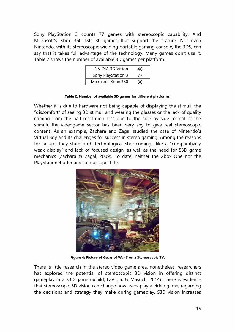
15
Sony PlayStation 3 counts 77 games with stereoscopic capability. And
Microsoft’s Xbox 360 lists 30 games that support the feature. Not even
Nintendo, with its stereoscopic wielding portable gaming console, the 3DS, can
say that it takes full advantage of the technology. Many games don’t use it.
Table 2 shows the number of available 3D games per platform.
NVIDIA 3D Vision 46
Sony PlayStation 3 77
Microsoft Xbox 360 30
Table 2: Number of available 3D games for different platforms.
Whether it is due to hardware not being capable of displaying the stimuli, the
“discomfort” of seeing 3D stimuli and wearing the glasses or the lack of quality
coming from the half resolution loss due to the side by side format of the
stimuli, the videogame sector has been very shy to give real stereoscopic
content. As an example, Zachara and Zagal studied the case of Nintendo’s
Virtual Boy and its challenges for success in stereo gaming. Among the reasons
for failure, they state both technological shortcomings like a “comparatively
weak display” and lack of focused design, as well as the need for S3D game
mechanics (Zachara & Zagal, 2009). To date, neither the Xbox One nor the
PlayStation 4 offer any stereoscopic title.
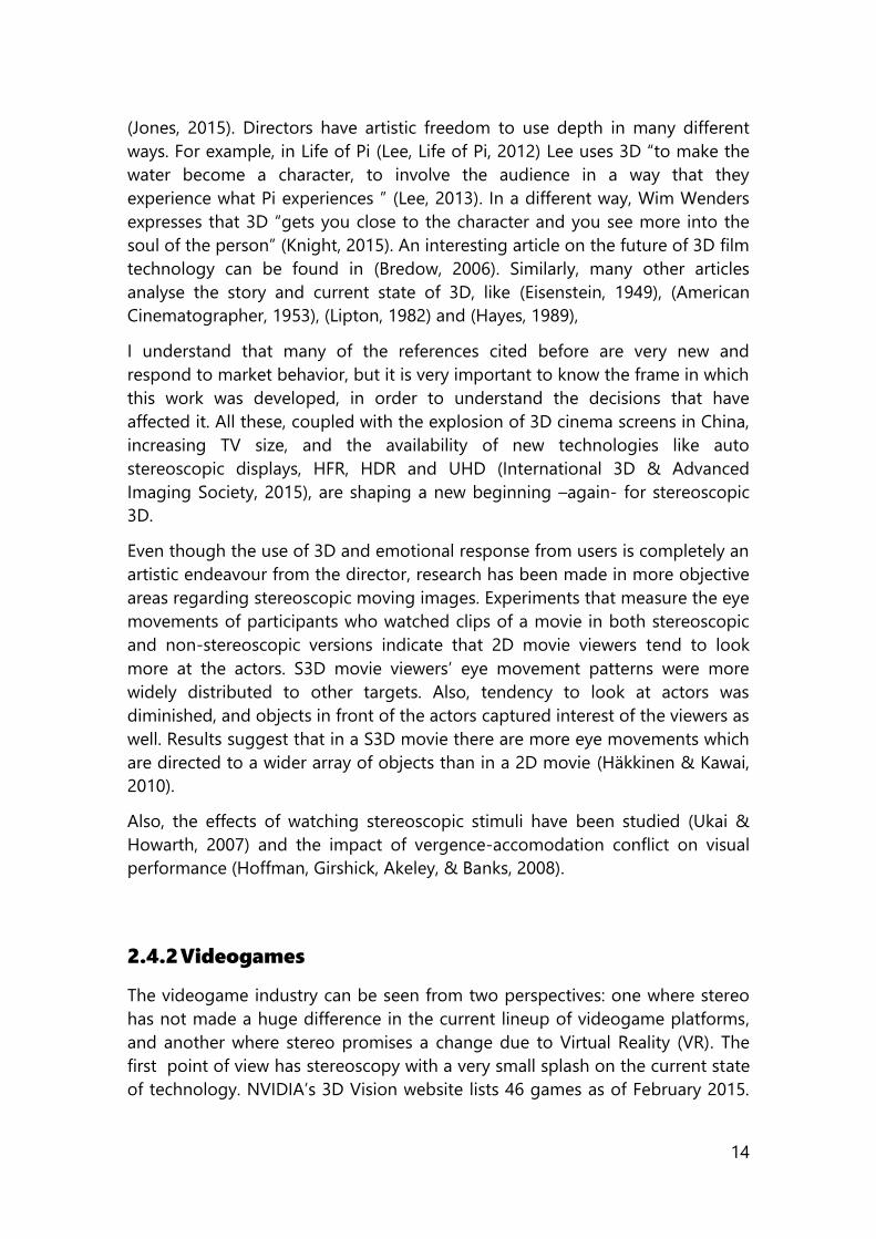
Figure 4: Picture of Gears of War 3 on a Stereoscopic TV.
There is little research in the stereo video game area, nonetheless, researchers
has explored the potential of stereoscopic 3D vision in offering distinct
gameplay in a S3D game (Schild, LaViola, & Masuch, 2014). There is evidence
that stereoscopic 3D vision can change how users play a video game, regarding
the decisions and strategy they make during gameplay. S3D vision increases
16
experience of spatial presence. It can also create additional value, as seen by
Rajae-Joordens while measuring the response of users playing Quake III both in
2D and 3D. Again, a reported higher positive emotions and stronger feelings of
presence were found, all this, with a relatively low amount of depth added to
the stimuli (Rajae-Joordens, 2008). Finally, an article that summarizes the
fundamentals of 3D game design (Schild & Masuch, 2011), while noticing that
to date there are no absolute measures for ensuring visual comfort in
interactive games, since physiological (inter ocular distance for example) and
technical factors (driver and display) always require evaluation of visual comfort
with the target group on target displays. The authors propose an interactive use
of S3D camera effects, stereoscopic game challenges/design ideas, S3D game
GUI and information visualization and extreme S3D. Hypo/hyperstereoscopy,
innovative camera angles (like Nintendo’s Super Street Fighter IV 3D Edition
(Nintendo, 2011) and its over the shoulder view), and abusive effects (Wilson &
Sicart, 2010 ) of the stereo are all ways of adapting stereo to the content.
2.4.3 Virtual Reality
Virtual Reality is not a new field. By the
decade of 1970, primitive computer-
generated graphics operating in real
time served as visualizations for flight simulators. By early 1980s better
hardware and software, coupled with motion-controlled platforms enabled
pilots to navigate through highly detailed virtual worlds. This was the decade
when videogames boomed, and several devices like the dataglove appeared,
allowing direct interaction with virtual environments (The Board of Trustees of
the University of Illinois, 1995). But even though the basic elements of VR have
existed since 1980, high-performance computers and powerful image rendering
capabilities are required to make VR work. In 1999, VR “barely worked” (Brooks,
1999), and it is until this year, 2016, that several consumer version VR headsets
are set to make an appearance. Devices like the Oculus Rift (Oculus, 2015),
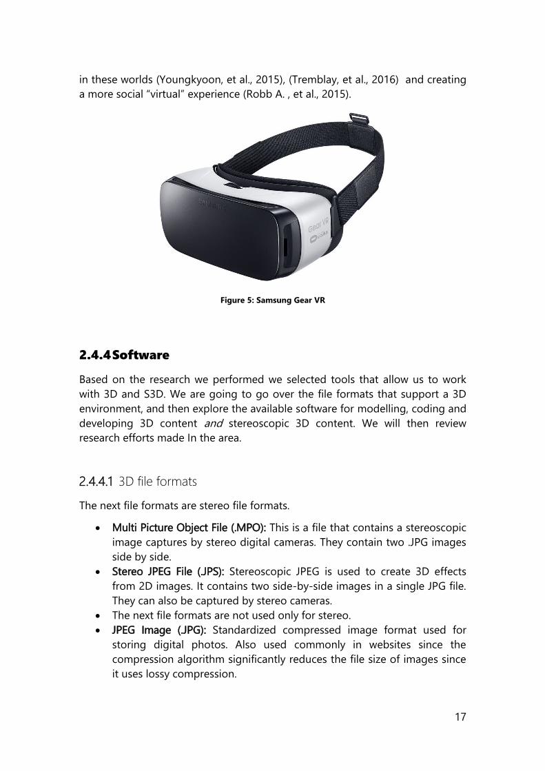
PlayStationVR from Sony (PlayStation, 2015), Gear VR (seen in Figure 5) from
Samsung (Samsung, 2015) and reVIVE from HTC and Valve (HTC, 2015) are
betting in directly putting the user in a virtual environment, where stereoscopic
content can be displayed, thanks to the different views that each eye is exposed
to. Taking into account the differences in interactions when creating a VR
experience, a VR UI is in essence, a stereoscopic user interface. Among the
differences are that a VR experience generally tries to create a virtual
environment. Therefore, research in this field is focused in simulation,
rehabilitation therapy (Wiederhold & Wiederhold, 2005), interaction techniques
A VR UI IS IN ESSENCE, A
STEREOSCOPIC USER
INTERFACE
17
in these worlds (Youngkyoon, et al., 2015), (Tremblay, et al., 2016) and creating
a more social “virtual” experience (Robb A. , et al., 2015).
Figure 5: Samsung Gear VR
2.4.4 Software
Based on the research we performed we selected tools that allow us to work
with 3D and S3D. We are going to go over the file formats that support a 3D
environment, and then explore the available software for modelling, coding and
developing 3D content and stereoscopic 3D content. We will then review
research efforts made In the area.
2.4.4.1 3D file formats
The next file formats are stereo file formats.
Multi Picture Object File (.MPO): This is a file that contains a stereoscopic
image captures by stereo digital cameras. They contain two .JPG images
side by side.
Stereo JPEG File (.JPS): Stereoscopic JPEG is used to create 3D effects
from 2D images. It contains two side-by-side images in a single JPG file.
They can also be captured by stereo cameras.
The next file formats are not used only for stereo.
JPEG Image (.JPG): Standardized compressed image format used for
storing digital photos. Also used commonly in websites since the
compression algorithm significantly reduces the file size of images since
it uses lossy compression.
18
Portable Network Graphics (.PNG): File type that contains a bitmap of
indexed colors and uses lossless compression, without the copyright
limitations GIF files have.
Graphical Interchange Format (.GIF): Image file that can contain up to 256
indexed colors. They are common in the web for small images. It is a
lossless format, since its clarity is not compromised with GIF
compression.
When using JPG, PNG or GIF files to create the stimuli, files are in a side by side,
top bottom (over/under) or anaglyph format. Table 9.1 found in (Mendiburu,
2009) exposes the 3D format compatibility with legacy 2D systems for video.
We can see that both in image and video, the resolution of the stimuli is cut to
half.
A full and comprehensive list of 3D related formats can be found in
(FileInfo.com, 2015).
2.4.4.2 3D Modelling
When designing and working with stereoscopic 3D, a 3D modelling software is
always a good tool for defining models and assets in our projects. They also
conform the basic toolset of certain engineering, architectural and product
design areas. Programs like Rhinoceros (Rhinoceros, 2015), Blender (blender,
2015) and Autodesk’s Maya and 3DS Max (Autodesk, 2015) allow 3D modelling,
animation and rendering. Of these programs, we recognize the value of the
open source Blender and the education program offered by Autodesk.
2.4.4.3 Research Examples
Though software applications have been shyer to introduce depth, research has
shown that 3D is good for aesthetic and functional reasons: when the S3D UI is
designed from the beginning for a holistic user experience, that is, one that
grants depth a utilitarian function. Mobile application examples, like the
phonebook contact app designed by Häkkilä et al. (Häkkilä, Posti, Koskenranta,
& Ventä-Olkkonen, 2013), or the in-car infotainment systems presented by Broy
et al. (Broy, André, & Schmidt, 2012) show that 3D representations have a
potential to improve the user experience and attractiveness of a user interface
without a negative impact on their workload. Highlighting and selecting items
(Huhtala, Karukka, Salmimaa, & Häkkilä, 2011), changing a user’s gaze pattern
in familiar UIs like search engine result pages (Gonzalez-Zuniga, Chistyakov, &
Carrabina, 2014) and other experiments that measure the desirability factor of
19
the stereo effect in certain UIs prove the benefits of adding depth to graphical
interfaces.
2.4.5 Stereoscopic Related Hardware
The association between the moniker “3D” and the term “hardware” has
expanded quite rapidly in the past years. From glasses-free 3D game consoles
to 3D printing, hardware was evolved to meet very specific needs. Though
hardware is not the main focus of this work, it is essential to it. We are going to
mention the displaying methods that we have used for our research. When we
say hardware we refer to displays, projectors and the associated glasses that
work with them. Knowing that the key to stereoscopy is getting a different
image to each eye, the way to accomplish this is by either polarizing or shutting
off lenses. The three main types of stereoscopic displaying technologies that we
used are anaglyph, passive and active. We will now review them. For an
assessment of 3DTV technologies, we can refer to (Onural, et al., 2006).
2.4.5.1 Anaglyphic encoding
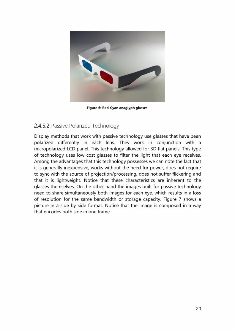
Red and cyan are the two colors that represent 3D. This is due to the anaglyphic
encoding that has been around for years. It is a way to use a basic color
encoding scheme to separate the content that is defined for each eye. While it
has limitations of color reproduction and low separation power, they are the
cheapest and only true really available method for the broadest distribution of
content without any special equipment. The very representative anaglyph
glasses are shown in Figure 6. With this technique, two points of view of an
image are gathered. The left eye view is then converted to red (blue and green
channels set to zero) and the right eye view is converted to cyan (red channel
set to zero). These two images are then combined. When they are fully
overlapped the result is the itself. This anaglyph therefore contains the left eye
view and the right eye view, but as different colours. When the image is viewed
through red green spectacles then the two images can be separated. This is
because the left eye only receives the red image and the right eye only the
green (Kightley, 2015).
20
Figure 6: Red-Cyan anaglyph glasses.
2.4.5.2 Passive Polarized Technology
Display methods that work with passive technology use glasses that have been
polarized differently in each lens. They work in conjunction with a
micropolarized LCD panel. This technology allowed for 3D flat panels. This type
of technology uses low cost glasses to filter the light that each eye receives.
Among the advantages that this technology possesses we can note the fact that
it is generally inexpensive, works without the need for power, does not require
to sync with the source of projection/processing, does not suffer flickering and
that it is lightweight. Notice that these characteristics are inherent to the
glasses themselves. On the other hand the images built for passive technology
need to share simultaneously both images for each eye, which results in a loss
of resolution for the same bandwidth or storage capacity. Figure 7 shows a
picture in a side by side format. Notice that the image is composed in a way
that encodes both side in one frame.

21
Figure 7: Side by side 3D picture taken from joshuatree3d.files.wordpress.com.
When referring to 3D TVs, the main mean in which consumers will experience
3D, the TV, has a filter that polarizes each line of pixels. This filter makes the
odd lines on the screen only visible to the left eye, and the even lines visible to
the right eye only.
2.4.5.3 Active Shutter Technology
Active technology presents only the image intended for the left eye while
blocking the right eye’s view. It then alternates the blocked side. It does this
rapidly enough so the user does not notice the interruptions. Both images are
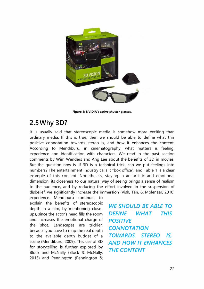
fused and the depth illusion is achieved. Commercial systems like the NVIDIA
3D Vision (Figure 8) utilize liquid crystal shutter glasses that have the capability
to make itself opaque when voltage is applied, thus, blocking the
corresponding frame. This technology works by syncing the displayed image
with the glasses. In theory, the information meant for the left eye is blocked
from the right eye by an opaque shutter. Televisions require to refresh fast
enough so each eye gets at least 60 frames per second. Active technology can
be found on plasma, LCD, LED LCD and all front and rear projectors.
22
Figure 8: NVIDIA's active shutter glasses.
2.5 Why 3D?
It is usually said that stereoscopic media is somehow more exciting than
ordinary media. If this is true, then we should be able to define what this
positive connotation towards stereo is, and how it enhances the content.
According to Mendiburu, in cinematography, what matters is feeling,
experience and identification with characters. We read in the past section
comments by Wim Wenders and Ang Lee about the benefits of 3D in movies.
But the question now is, if 3D is a technical trick, can we put feelings into
numbers? The entertainment industry calls it “box office”, and Table 1 is a clear
example of this concept. Nonetheless, staying in an artistic and emotional
dimension, its closeness to our natural way of seeing brings a sense of realism
to the audience, and by reducing the effort involved in the suspension of
disbelief, we significantly increase the immersion (Vish, Tan, & Molenaar, 2010)
experience. Mendiburu continues to
explain the benefits of stereoscopic
depth in a film, by mentioning close-
ups, since the actor’s head fills the room
and increases the emotional charge of
the shot. Landscapes are trickier,
because you have to map the real depth
to the available depth budget of a
scene (Mendiburu, 2009). This use of 3D
for storytelling is further explored by
Block and McNally (Block & McNally,
2013) and Pennington (Pennington &
WE SHOULD BE ABLE TO
DEFINE WHAT THIS
POSITIVE
CONNOTATION
TOWARDS STEREO IS,
AND HOW IT ENHANCES
THE CONTENT
23
Giardina, 2012).
According to Tam et al., S3D image sequences are preferred to their non-stereo
versions, and in a scene with depth, greater depth is perceived in a S3D
composition. Sharpness stays lower or the same (Tam, Stelmach, & Corriveau,
1998). Now if we want to quantify this, we could look into measuring increased
fun and excitement, increased feeling of reality and solidity (Lambooij, 2005),
feeling of presence (IJsselsteijn, Ridder, Freeman, Avons, & Bouwhuis, 2001) and
(Freeman, Lessiter, & W. Ijsselsteijn, 2001) or just aesthetic experiences (Kant,
1961) as factors that describe this enhancement (Häkkinen, et al., 2008).
2.6 Summary of the chapter
This chapter talks about the basics of stereoscopic imaging starting by
explaining how projections are ways of mapping 3D points to a 2D space to
how our brain uses retinal disparity to reconstruct depth from our visual
system. The relation of these topics with the different types of visual cues
(oculomotor, monocular and binocular), and how they contribute to 3D.
The most powerful visual cue being parallax, and how this technique is
exploited by the film industry, videogames and software to create stereoscopic
assets. These assets require special software and hardware to be visualized,
shared and created. It is in this software space where the main contribution of
the current work resides.
Finally, an introduction into the question of why 3D matters, from a creative
point of view, to get some inspiration while we start to look into a fundamental
part of the 3D app pipeline, and how to create the tools for S3D development.
24
3 Creating the tools for S3D Development
We have mentioned types of media that take advantage of stereoscopic 3D and
reviewed the hardware we need to display it. Now we will explore the
alternatives that we have if we want to implement S3D stimuli.
In order to create stereoscopic user interfaces, we tried several technologies to
see how capable they were for developing a stereo compatible interactive UI.
By studying these platforms, we would like not only to know which one is
currently the best option but also, what are the main characteristics that a
future platform devoted to that purpose should have. Following we present our
findings per tested platform.
3.1 CANVAS
The fifth revision of the Hypertext Mark-up Language (W3C HTML WG, 2014)
has now the ‘recommendation’ status by the World Wide Web Consortium. This
is a platform that we look upon to create stereo stimuli. This revision is relevant
because it introduces syntactic features related to multimedia objects (W3C,
2014). It achieves this while avoiding third party plug-ins, applications and
players such as Adobe Flash and Microsoft Silverlight, which rose security,
reliability, battery, performance and cross-platform concerns in the past. Some
of the newly defined tags are <video>, <audio> and <canvas>. As their names
imply, they are designed to facilitate the inclusion and management of
multimedia content on the web. It is implemented in a way that the mark-up
maintains its readability and consistency among devices.
With this milestone achieved from the platform, we developed a drawing toolkit
to create stereoscopic side-by-side 3D stimuli. The toolkit is based in the
HTML5 canvas element and drawing is achieved using intermediate stereo
scripting methods that correspond to the ‘2d’ context of the canvas. We have
named the toolkit ‘canv.3d’ (formerly codenamed SXS3DCNV -Side by Side 3D
Canvas) and explain it in the following paragraphs.
As stated earlier, it is based in canvas which is a revolutionary feature present in
HTML5 that enables powerful graphics for rich Internet Applications. It
represents a resolution-dependent bitmap canvas, which can be used for
rendering graphs, game graphics, or other visual images on the fly (W3C, 2014).
Its use consists in a JavaScript API for drawing in an HTML canvas tag. The
drawing methods in the API are accessed through a drawing context. It is a low-
level procedural model that updates a bitmap, yet keeps no track of the scene
25
graph. The fact that there is no track of the scene-graph makes anything that
we draw on the canvas part of the final composition. This is the main difference
between HTML5 canvas and Scalable Vector Graphics (SVG).
HTML5 Canvas has two different drawing contexts: (i) the “2d” drawing context
and (ii) the “3D” context. The former is invoked by passing the ‘2d’ parameter
when acquiring the drawing context and allows scripting to draw geometrical
shapes and paths, as well as text, images and video. All this in a flat 2D surface.
The latter is invoked by passing the ‘webgl’ parameter. This different context
enables WebGL in the canvas and allows the scripting of meshes to create a 3D
model in a virtual 3D scene, with X, Y and Z coordinates. Both contexts are very
different in their scopes, in the scripting they accept, and yet none of them are
stereoscopic by default.
3.1.1 Benefits
We chose HTML5’s canvas element to create the stereoscopic compositions
because we immediately gain compatibility with a broad scope of HTML5
devices. Any modern browser capable of rendering HTML5 will most likely
support this element. In their latest builds, Edge, Internet Explorer, Firefox,
Opera, Chrome and Safari support the canvas tag. Canvas allows for an easy
conversion of a webpage into a dynamic web application that uses rich
multimedia elements.
Canvas is a native HTML5 element, present in the Document Object Model
(DOM) of the page. Because of this, canvas can interact with other elements
present in the DOM, which means that even running in its own drawing context,
it can communicate with forms and other elements in the page. This rules out
the need for third party plug-ins.
Also, the library being written in JavaScript allows for interaction with other
scripts and diverse input devices that feature a JavaScript API. Among these
devices we can mention the Kinect and the LEAP Motion.
Additionally, since all the compositions created on the canvas are expressed in
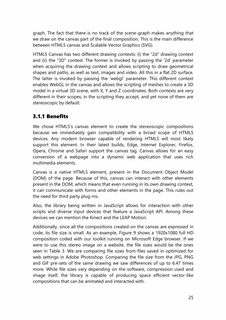
code, its file size is small. As an example, Figure 9 shows a 1920x1080 full HD
composition coded with our toolkit running on Microsoft Edge browser. If we
were to use this stereo image on a website, the file sizes would be the ones
seen in Table 3. We are comparing file sizes from files saved in optimized for
web settings in Adobe Photoshop. Comparing the file size from the JPG, PNG
and GIF pre-sets of the same drawing we saw differences of up to 6.47 times
more. While file sizes vary depending on the software, compression used and
image itself, the library is capable of producing space efficient vector-like
compositions that can be animated and interacted with.
26
Figure 9: Stereo Composition on a browser with canv.3d.
Web Preset Size Ratio
JPEG High 90.59K 647%
JPEG Medium 49.07K 350%
JPEG Low 35.71K 255%
GIF 128 Dithered 63.27 452%
GIF 32 No Dither 51.63K 368%
PNG-8 38.03K 271%
PNG-24 56.17K 401%
CANV.3D 14K 100%
Table 3: File size ratios for composition of image in Figure 8.
3.1.2 Challenges
We must state that we are considering building stereo stimuli only for the
‘2d’context leaving aside WebGL. Our main focus is to play with depth in
different elements of the drawing and not playing with the full 3D model and
perspective that a WebGL scene offers. The main reason behind this is that we
created this toolkit for the creation of stimuli to perform research on graphical
user interfaces, charting and vector-like animations.
27
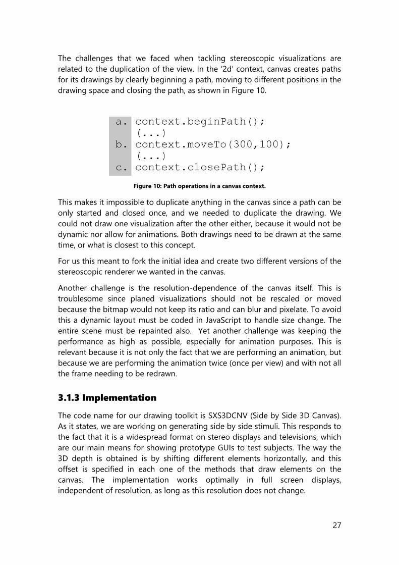
The challenges that we faced when tackling stereoscopic visualizations are
related to the duplication of the view. In the ‘2d’ context, canvas creates paths
for its drawings by clearly beginning a path, moving to different positions in the
drawing space and closing the path, as shown in Figure 10.
Figure 10: Path operations in a canvas context.
This makes it impossible to duplicate anything in the canvas since a path can be
only started and closed once, and we needed to duplicate the drawing. We
could not draw one visualization after the other either, because it would not be
dynamic nor allow for animations. Both drawings need to be drawn at the same
time, or what is closest to this concept.
For us this meant to fork the initial idea and create two different versions of the
stereoscopic renderer we wanted in the canvas.
Another challenge is the resolution-dependence of the canvas itself. This is
troublesome since planed visualizations should not be rescaled or moved
because the bitmap would not keep its ratio and can blur and pixelate. To avoid
this a dynamic layout must be coded in JavaScript to handle size change. The
entire scene must be repainted also. Yet another challenge was keeping the
performance as high as possible, especially for animation purposes. This is
relevant because it is not only the fact that we are performing an animation, but
because we are performing the animation twice (once per view) and with not all
the frame needing to be redrawn.
3.1.3 Implementation
The code name for our drawing toolkit is SXS3DCNV (Side by Side 3D Canvas).
As it states, we are working on generating side by side stimuli. This responds to
the fact that it is a widespread format on stereo displays and televisions, which
are our main means for showing prototype GUIs to test subjects. The way the
3D depth is obtained is by shifting different elements horizontally, and this
offset is specified in each one of the methods that draw elements on the
canvas. The implementation works optimally in full screen displays,
independent of resolution, as long as this resolution does not change.
28
The drawing toolkit is a JavaScript file that can easily be imported to any
webpage. Then another file that contains the user’s drawing is set as source.
SXS3DCNV defines a set of functions that draw on a canvas (or set of canvases)
stereoscopically. Every ‘2d’ context method has a stereo counterpart. These
‘stereo’ methods, identified by the prefix “s3d”, take care of scaling, positioning
and drawing what the user codes. This keeps the drawing and the toolkit apart
and easily updateable.
The initial prototype consisted of a canvas that allowed the creation of dual
sides by clipping the canvas and drawing in each resulting side. This strategy
presents some problems as the path operations could not be replicated on
each half (since one context can handle one open path at a time, and we
require two) and that the clipping implementation was accompanied with
painful performance on certain browsers like Firefox 33.1.
To bypass the problems that multiple path drawing represented, we forked the
code into SXS3DCNV Solo and SXS3DCNV Duo. The difference between both
was that Solo draws on one canvas while Duo draws on two. This is the same as
managing one or two different contexts in the same drawing method. It also
means that we are able to draw at the “same time” on each one of the
canvases.
The current version of the library only features code that draws on a set of
several pairs of canvases at once. It is based in work presented in the 3DUI 2015
symposium (González-Zúñiga & Carrabina, Hacking HTML5 Canvas to Create a
Stereo 3D Renderer, 2015) and has since then been renamed and released as
canv.3d.
3.1.4 Performance
The resulting is a JavaScript library that produces stereoscopic compositions.
These compositions are achieved by creating side by side stimuli that shift
elements horizontally to generate the depth effect. The toolkit exposes a
drawing API that corresponds to methods of the ‘2d’ context of the canvas.
Primary uses for this element are games and animations, since it allows the
drawing and manipulation of the element area as a blank linen.
We tested performance of animating in this stereo canvas by drawing hundreds
up to thousands of rectangles generated each frame. We recorded the number
of frames per second that we could achieve in desktop and mobile platforms
(both browsers and devices) and the results are shown in Figure 11 and Figure
12. In both figures, the Y axis represents frames per second, while the X axis is
number of rectangles drawn in the test.
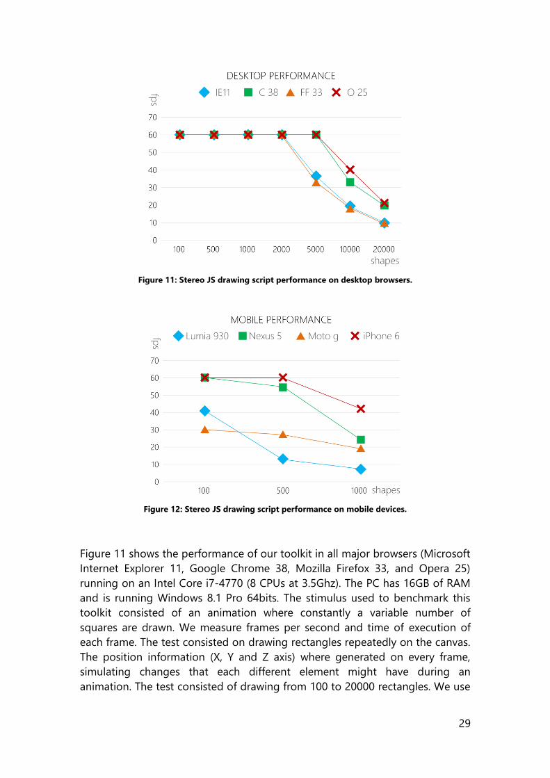
29
Figure 11: Stereo JS drawing script performance on desktop browsers.
Figure 12: Stereo JS drawing script performance on mobile devices.
Figure 11 shows the performance of our toolkit in all major browsers (Microsoft
Internet Explorer 11, Google Chrome 38, Mozilla Firefox 33, and Opera 25)
running on an Intel Core i7-4770 (8 CPUs at 3.5Ghz). The PC has 16GB of RAM
and is running Windows 8.1 Pro 64bits. The stimulus used to benchmark this
toolkit consisted of an animation where constantly a variable number of
squares are drawn. We measure frames per second and time of execution of
each frame. The test consisted on drawing rectangles repeatedly on the canvas.
The position information (X, Y and Z axis) where generated on every frame,
simulating changes that each different element might have during an
animation. The test consisted of drawing from 100 to 20000 rectangles. We use
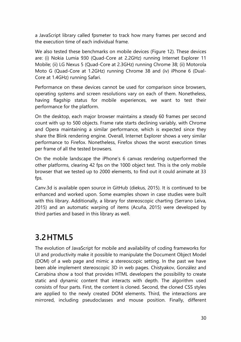
30
a JavaScript library called fpsmeter to track how many frames per second and
the execution time of each individual frame.
We also tested these benchmarks on mobile devices (Figure 12). These devices
are: (i) Nokia Lumia 930 (Quad-Core at 2.2GHz) running Internet Explorer 11
Mobile; (ii) LG Nexus 5 (Quad-Core at 2.3GHz) running Chrome 38; (ii) Motorola
Moto G (Quad-Core at 1.2GHz) running Chrome 38 and (iv) iPhone 6 (Dual-
Core at 1.4GHz) running Safari.
Performance on these devices cannot be used for comparison since browsers,
operating systems and screen resolutions vary on each of them. Nonetheless,
having flagship status for mobile experiences, we want to test their
performance for the platform.
On the desktop, each major browser maintains a steady 60 frames per second
count with up to 500 objects. Frame rate starts declining variably, with Chrome
and Opera maintaining a similar performance, which is expected since they
share the Blink rendering engine. Overall, Internet Explorer shows a very similar
performance to Firefox. Nonetheless, Firefox shows the worst execution times
per frame of all the tested browsers.
On the mobile landscape the iPhone’s 6 canvas rendering outperformed the
other platforms, clearing 42 fps on the 1000 object test. This is the only mobile
browser that we tested up to 2000 elements, to find out it could animate at 33
fps.
Canv.3d is available open source in GitHub (diekus, 2015). It is continued to be
enhanced and worked upon. Some examples shown in case studies were built
with this library. Additionally, a library for stereoscopic charting (Serrano Leiva,
2015) and an automatic warping of items (Acuña, 2015) were developed by
third parties and based in this library as well.
3.2 HTML5
The evolution of JavaScript for mobile and availability of coding frameworks for
UI and productivity make it possible to manipulate the Document Object Model
(DOM) of a web page and mimic a stereoscopic setting. In the past we have
been able implement stereoscopic 3D in web pages. Chistyakov, González and
Carrabina show a tool that provides HTML developers the possibility to create
static and dynamic content that interacts with depth. The algorithm used
consists of four parts. First, the content is cloned. Second, the cloned CSS styles
are applied to the newly created DOM elements. Third, the interactions are
mirrored, including pseudoclasses and mouse position. Finally, different
31
elements in a web page are shifted left or right based on a predefined array of
pixel separation (Chistyakov, Gonzalez-Zuniga, & Carrabina, 2013).
For this approach we utilize jQuery to duplicate and modify the DOM and we
show the power of client scripting for stereoscopic transformation of existing
content. This tool is available from (Chistyakov, 3dsjq, 2015).
3.2.1 Benefits
The main advantage of this type of DOM manipulation is that it is a very
straightforward way of creating content for stereo displays. It shares many of
the advantages that the ‘2d’ context of the canvas has like cross device
rendering. It also has many of the same disadvantages that the same ‘2d’
context suffers. This technique duplicates every element on the page, having to
render twice as many DOM objects and dealing with complex interactions. The
3D works well if no script is running that dynamically changes elements on the
page (mainly due to ids and classes that uniquely identify elements on the
script). In our examples the 2014 3D Creative Summit website was partially
cloned, having issues recreating of the interactive banner on top. Also, in our
tests creating basic games, canvas proved superior to HTML5 because it is
hardware accelerated and is actually just one big canvas instead of several
different objects. Having said this, we see the HTML5 toolkit plus the canvas
drawing toolkit as a very powerful and easy way to create stereo content.
Cloning the DOM elements still represents one of the easiest ways to port
existing web content to 3D.
3.2.2 Challenges
Among the limitations we encountered with this implementation is that for
HTML5, different browser implementations render content differently. This
might produce slightly different results/behaviors on the converted content.
Cloning the DOM also duplicates the number of DOM elements the browser
handles, having to use twice the amount of resources. It is also difficult to
manage dynamic scripts that alter the DOM and CSS styles themselves in
runtime.
3.3 Three.JS
THREE is an abstraction layer that stands over WebGL. Its purpose, as stated by
its website is to “make WebGL -3D in the browser- easy to use”. This because
“While a simple cube in raw WebGL would turn out of hundreds of lines of
Javascript and shader code, a Three.js equivalent is only a fraction of that”.

32
3.3.1 Benefits
The benefits of THREE are that it allows a simple way to create 3D objects and
spaces and render them in different outputs, like WebGL, ASCII and Canvas.
This gives THREE a lot of flexibility to adapt to different devices. THREE can use
different renderers but ideally using the ‘webgl’ context of the HTML5 canvas is
desired. THREE/WebGL provide a 3D (2.5D) engine that supports rendering of
meshes in space. It can also create the stereoscopic scene by adding another
camera and projecting to a second viewport. This is better than the
canvas/HTML implementations, where every element must be cloned. A final
advantage of using THREE is that most modern browsers support WebGL,
making the content created with THREE easy to view on desktop and mobile
devices.
3.3.2 Challenges
The challenges of utilizing THREE is that it requires to build infrastructure to
manage events. If we want to create a user interface that manages events, we
must attach the events and handle them appropriately. Also, ray-casting and
item selection are more complex when dealing with space.
3.3.3 Implementation
The way we have created a stereoscopic view is by setting two cameras and
commanding the renderer to paint a distorted (horizontally scaled) version of
each camera in different halves of the screen. This creates the stimuli in a very
similar way that the Unity Engine (Unity Technologies, 2016) would accomplish
it, and avoids the performance limitations that manually duplicating a view can
have, as is the case with the ‘2d’ context of the canvas or HTML5/jQuery
solutions.
Three.JS has also recently introduced a collection of effects that include a
THREE.StereoEffect and a THREE.OculusRiftEffect. These render side by side and
in the case of the OculusRiftEffect include the barrel effect. A THREE scene is
powerful and flexible enough to allow the creation of both flat and analog type
of applications.
3.4 Windows Presentation Foundation
In 2007 Microsoft presented to the world Windows Vista. This operating system
brought some changes to the .NET developer environment introducing WPF,
WCF and WWF (Presentation, Communication and Workflow foundations
respectively). These technologies would supersede previous implementations of
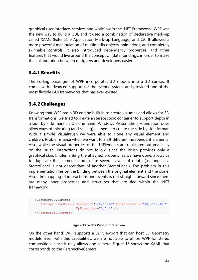
33
graphical user interface, services and workflow in the .NET Framework. WPF was
the new way to build a GUI, and it used a combination of declarative mark-up
called XAML (Extensible Application Mark-up Language) and C#. It allowed a
more powerful manipulation of multimedia objects, animations, and completely
skinnable controls. It also introduced dependency properties, and other
features that would live around the concept of (data) bindings, in order to make
the collaboration between designers and developers easier.
3.4.1 Benefits
The coding paradigm of WPF incorporates 3D models into a 3D canvas. It
comes with advanced support for the events system, and provided one of the
most flexible GUI frameworks that has ever existed.
3.4.2 Challenges
Knowing that WPF has a 3D engine built in to create volumes and allows for 3D
transformations, we tried to create a stereoscopic container to support depth in
a side by side manner. On one hand, Windows Presentation Foundation does
allow ways of mirroring (and scaling) elements to create the side by side format.
With a simple VisualBrush we were able to clone any visual element and
children. Problems arise when we want to shift different independent elements.
Also, while the visual properties of the UIElements are replicated automatically
on the brush, interactions do not follow, since the brush provides only a
graphical skin. Implementing the attached property, as we have done, allows us
to duplicate the elements and create several layers of depth (as long as a
StereoPanel is not descendant of another StereoPanel). The problem in this
implementation lies on the binding between the original element and the clone.
Also, the mapping of interactions and events is not straight-forward since there
are many inner properties and structures that are tied within the .NET
framework.
Figure 13: WPF's Viewport3D camera.
On the other hand, WPF supports a 3D Viewport that can host 3D Geometry
models. Even with this capabilities, we are not able to utilize WPF for stereo
compositions since it only allows one camera. Figure 13 shows the XAML that
corresponds to the PerspectiveCamera.
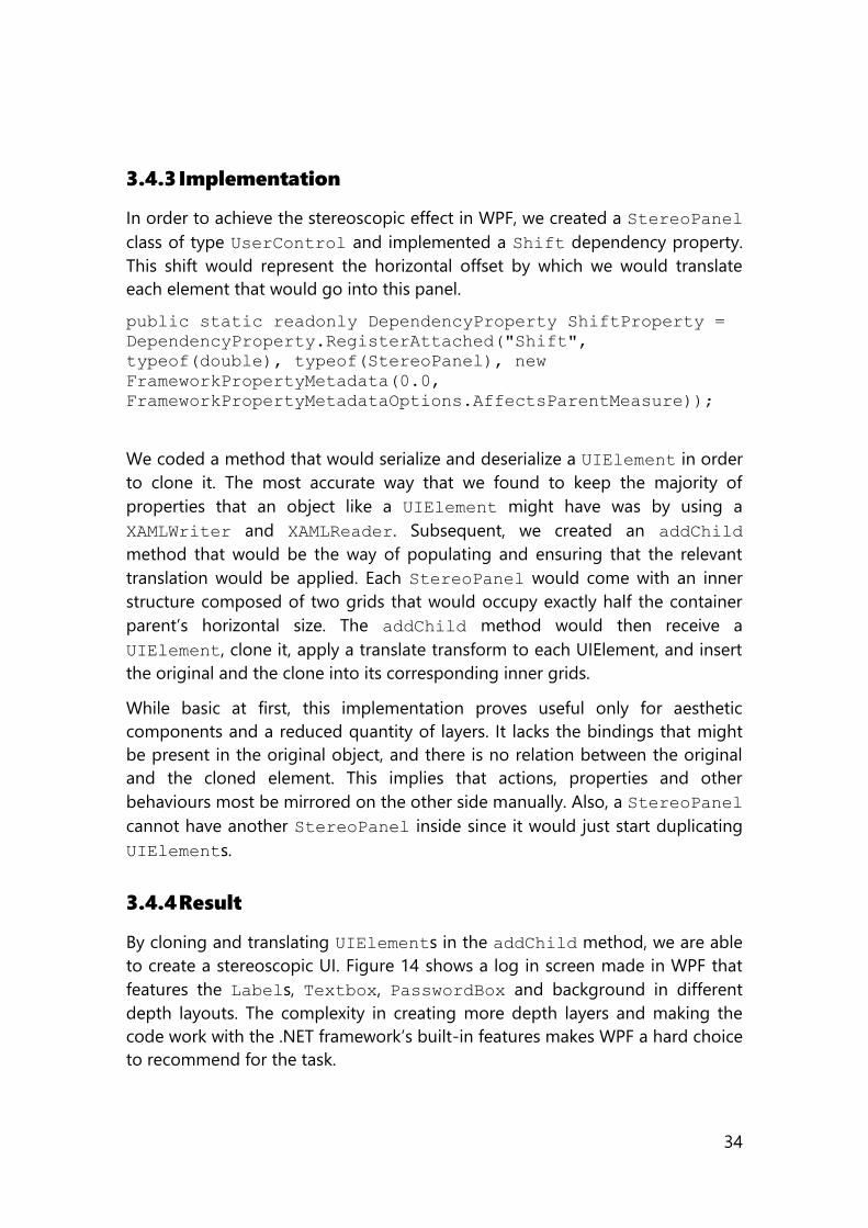
34
3.4.3 Implementation
In order to achieve the stereoscopic effect in WPF, we created a StereoPanel
class of type UserControl and implemented a Shift dependency property.
This shift would represent the horizontal offset by which we would translate
each element that would go into this panel.
public static readonly DependencyProperty ShiftProperty =
DependencyProperty.RegisterAttached("Shift",
typeof(double), typeof(StereoPanel), new
FrameworkPropertyMetadata(0.0,
FrameworkPropertyMetadataOptions.AffectsParentMeasure));
We coded a method that would serialize and deserialize a UIElement in order
to clone it. The most accurate way that we found to keep the majority of
properties that an object like a UIElement might have was by using a
XAMLWriter and XAMLReader. Subsequent, we created an addChild
method that would be the way of populating and ensuring that the relevant
translation would be applied. Each StereoPanel would come with an inner
structure composed of two grids that would occupy exactly half the container
parent’s horizontal size. The addChild method would then receive a
UIElement, clone it, apply a translate transform to each UIElement, and insert
the original and the clone into its corresponding inner grids.
While basic at first, this implementation proves useful only for aesthetic
components and a reduced quantity of layers. It lacks the bindings that might
be present in the original object, and there is no relation between the original
and the cloned element. This implies that actions, properties and other
behaviours most be mirrored on the other side manually. Also, a StereoPanel
cannot have another StereoPanel inside since it would just start duplicating
UIElements.
3.4.4 Result
By cloning and translating UIElements in the addChild method, we are able
to create a stereoscopic UI. Figure 14 shows a log in screen made in WPF that
features the Labels, Textbox, PasswordBox and background in different
depth layouts. The complexity in creating more depth layers and making the
code work with the .NET framework’s built-in features makes WPF a hard choice
to recommend for the task.
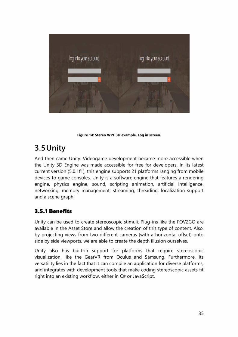
35
Figure 14: Stereo WPF 3D example. Log in screen.
3.5 Unity
And then came Unity. Videogame development became more accessible when
the Unity 3D Engine was made accessible for free for developers. In its latest
current version (5.0.1f1), this engine supports 21 platforms ranging from mobile
devices to game consoles. Unity is a software engine that features a rendering
engine, physics engine, sound, scripting animation, artificial intelligence,
networking, memory management, streaming, threading, localization support
and a scene graph.
3.5.1 Benefits
Unity can be used to create stereoscopic stimuli. Plug-ins like the FOV2GO are
available in the Asset Store and allow the creation of this type of content. Also,
by projecting views from two different cameras (with a horizontal offset) onto
side by side viewports, we are able to create the depth illusion ourselves.
Unity also has built-in support for platforms that require stereoscopic
visualization, like the GearVR from Oculus and Samsung. Furthermore, its
versatility lies in the fact that it can compile an application for diverse platforms,
and integrates with development tools that make coding stereoscopic assets fit
right into an existing workflow, either in C# or JavaScript.
36
3.5.2 Implementation
The prototype that we developed to create stereoscopic 3D GUIs consists of a
C# script that is attached to a camera and some rendering modifications to
create the dual side by side of top bottom view.
Figure 15: S3DCamera game object properties.
3.5.3 Performance
Unity has been one of the most powerful engines that we have had at our
disposal to create stereo stimuli. It’s free of charge, C# or JS environment, cross
platform support and built-in 3D engine make it a flexible and convenient tool
to address the addition of space in a user interface. Figure 15 shows how our
script looks in the Unity IDE.
With Unity, we had easy porting and configuration of an application to run on
multiple devices, by being able to adjust the graphics settings according to the
graphics power of the targeted device. Appendix C. Unity CameraManagement
Script shows the basic class that enables the stereoscopic capabilities in Unity.
An added benefit of implementing 3D with a tool like Unity is that the
interactions occur from the camera’s point of view (or combination of camera
and input device like mouse) and relative to the current viewport. This means
we do not have to implement nor calculate positions or new elements to
interact with.
3.6 Summary of the chapter
This chapter presents the first relevant part of our contribution. To define a
pipeline for stereoscopic app development, it is mandatory to have create tools
37
to develop these applications. Therefore, we analyse technologies that are
available for developers and evaluate their utility to code stereoscopic apps, for
web and native environments. We examine HTML5 Canvas, HTML5, THREE.JS,
Windows Presentation Foundation, and Unity.
For HTML5 Canvas, we developed a library that allows the creation of
stereoscopic compositions over a web canvas. This tool is made public and
open source. HTML5 follows a similar outcome. We explain how a 3D renderer
can be set with THREE.JS as well. WPF does not provide the necessary flexibility
to create stereoscopic assets so is therefore not recommended. Finally, we
present a stereoscopic camera management script for Unity, the video game
engine. This script takes two cameras from a scene and creates a stereo rig that
can act in a side by side or top-bottom format. Once we have researched and
created tools for stereo development, we need to see how we can measure
human factors for the out coming applications.

38
Section Two
In depth Software In the present section we take the concepts, tools and technologies elaborated
in previous chapters and examine how they affect software. We look into the
Human Factors for Measurement, focusing in User Experience (UX) constructs
that are standard in software development. With these concepts covered in
chapter 4 we move into the case studies documented in chapter 5, both in how
technology created the stimuli and how the aforementioned human factors
behave with the stereoscopic 3D applied to the user interfaces. Chapter 4
presents the existing UX concepts that will be observed in Chapter 5.
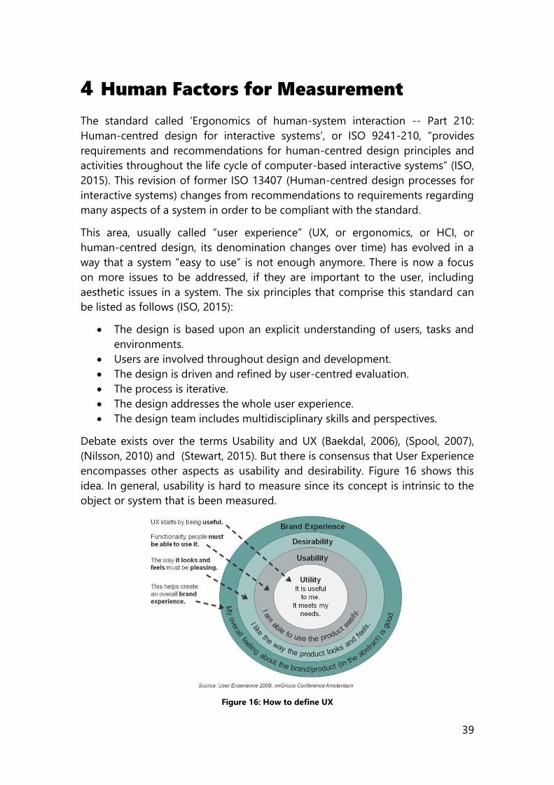
39
4 Human Factors for Measurement
The standard called ‘Ergonomics of human-system interaction -- Part 210:
Human-centred design for interactive systems’, or ISO 9241-210, “provides
requirements and recommendations for human-centred design principles and
activities throughout the life cycle of computer-based interactive systems” (ISO,
2015). This revision of former ISO 13407 (Human-centred design processes for
interactive systems) changes from recommendations to requirements regarding
many aspects of a system in order to be compliant with the standard.
This area, usually called “user experience” (UX, or ergonomics, or HCI, or
human-centred design, its denomination changes over time) has evolved in a
way that a system “easy to use” is not enough anymore. There is now a focus
on more issues to be addressed, if they are important to the user, including
aesthetic issues in a system. The six principles that comprise this standard can
be listed as follows (ISO, 2015):
The design is based upon an explicit understanding of users, tasks and
environments.
Users are involved throughout design and development.
The design is driven and refined by user-centred evaluation.
The process is iterative.
The design addresses the whole user experience.
The design team includes multidisciplinary skills and perspectives.
Debate exists over the terms Usability and UX (Baekdal, 2006), (Spool, 2007),
(Nilsson, 2010) and (Stewart, 2015). But there is consensus that User Experience
encompasses other aspects as usability and desirability. Figure 16 shows this
idea. In general, usability is hard to measure since its concept is intrinsic to the
object or system that is been measured.
Figure 16: How to define UX
40
It was mentioned in section 2.5 that we should be able to define what this
positive connotation towards stereo is and how it enhances the content. We will
attribute these enhancements to constructs related to User Experience (UX) like
usability and desirability. We will also analyse other key performance indicators
(KPI) that are related to the task in hand (like efficiency, effectiveness, eye
tracking, gaze-time, time-to-completion or depth-perception). As a final part of
this chapter, we will also present a scientific proposal based on a clustering
exercise that we performed in order to group terms related to desirability,
providing in our opinion a better way to describe an application.
4.1 Usability
Formally, part 11 of the Ergonomics of human system interaction standard,
titled “Usability: Definitions and concepts” (ISO/DIS 9241-11 , 2016) defines the
term “usability” in section 2.1.1 as the “extent to which a system, product or
service can be used by specified users to achieve specified goals with
effectiveness, efficiency and satisfaction in a specified context of use”. Other
experts in the area, like Nielsen, define usability as being about learnability,
efficiency, memorability, errors and satisfaction (Nielsen J. , 1993).These are
indicators related with the task as a whole and coherent with the definition
given in the standard. We say coherent because errors, learnability,
memorability are linked to time to task completion and completion/failure rate,
which are linked to efficiency and
effectiveness. Measuring usability is
complex, since its concept is intrinsic to
the object or system that is being
measured. In order to achieve this,
several methods like the Software
Usability Measurement Inventory
(SUMI) questionnaire (Kirakowski, 1993),
Standardized User Experience Percentile
Rank Questionnaire (SUPR-Q) (Sauro J. ,
The Essential Elements Of A Successful
Website, 2011), Single Usability Metric
(SUM) (Sauro & Kindlund, 2005), or
System Usability Scale (SUS) (Brooke,
1996) can be used.
4.1.1 How to Measure Usability
We selected SUS to measure usability. Nonetheless, strengths and
shortcomings of the alternatives follow. The Software Usability Measurement
Inventory (SUMI) is a rigorously tested and proven method of measuring
“USABILITY, AS A
CONSTRUCT, CAN BE
EMBODIED AS A
COMBINATION OF
EFFECTIVENESS,
EFFICIENCY AND
SATISFACTION IN A
SPECIFIED CONTEXT OF
USE.”
41
software quality from the end user’s point of view. Among its advantages are
that it is available in different languages, carefully translated and validated.
Since the main target group are students in Spain this was beneficial.
The Standardized User Experience Percentile Rank Questionnaire is mainly for
websites and includes in its score factors like Trust & Credibility, Appearance
and Loyalty and has a high correlation with more generic metrics like the
System Usability Scale (r = .87, p < .001).
The System Usability Scale defined by John Brooke (Brooke, 1996) provides a
simple, ten-item scale giving a global view of subjective assessment of usability.
It doesn’t require many users to provide reliable results, and it currently stands
as the standard way of measuring usability.
We chose SUS since it fulfils the need for a tool that could quickly and easily
collect a user’s subjective rating of a product’s usability (Bangor, Kortum, &
Miller, 2008) and because SUS has shown to provide superior assessments of
website usability compared to other questionnaires (like QUIS, CSUQ) (Tullis &
Stetson, 2004) and “produces similar results to other, more extensive attitude
scales that are intended to provide deeper insights into a user’s attitude to the
usability of a system” (Sauro, 2011). As examples, this correlation is .79 with
SUMI and r=.948 with WAMMI scores. Also, a Spanish version of the SUS is
available in (Calvo-Fernández, Ortega, & Valls).
Moreover, the validity of SUS with today’s systems and technologies cannot be
denied. Even if these technologies were nonexistent 25 years ago and radically
different from the initial ones it was meant to quickly evaluate, the individual
statements in SUS are not particularly meaningful in themselves and are
generally applicable regardless of technology. The System Usability Scale was
built in a way that the sum of the 10 ratings lead to a general measure of
perceived usability (Brooke, 2013). We can choose SUS and be confident it is a
valid and reliable measuring tool, with results comparable among them even if
the systems are completely different, all this by asking a small number of users.
4.2 Desirability
Desirability. 1 plural: desirable conditions. 2: the quality, fact or degree of being
desirable (Merriam-Webster, 2015). Desirable. Having good or pleasing
qualities: worth having or getting (Merriam-Webster, 2015).
Desirability is a construct generally associated with the user experience of a
system. The reason why we focus in this concept is because if you combine SUS
with a more qualitative testing mechanism, we are able to get the most out of
what is going on with the UX. Adding desirability provides a layer of qualitative
impact of the system.
42
Desirability is a characteristic that we look for when we develop experiences, yet
its subjective nature makes it difficult to quantify. This goes beyond the “is the
product usable”, therefore, methods like rating scales, list of descriptors and
open-ended questions are the most prevalent among the ways to recollect
information about this. The methods mentioned before, all share that we ask
the user for information, and that is the reason why they are referred to as
“Self-Reported Metrics” (Tullis & Albert, 2008). The problem with these self-
reported metrics is its inherent subjectivity, differences in interpretations of
concepts and openness in the analysis of results.
4.2.1 How to Measure
Desirability
To measure desirability and the
emotional response of a design or a
product, we use Microsoft Product
Reaction Cards (Benedek & Miner,
2002). These are a set of 118 cards
presented by Benedek and Miner that
contain adjectives to describe a
product. The authors state among its
advantages the fact that the method
does not rely on questionnaire or rating
scales, and that users do not have to generate words themselves. The terms
were selected from prior research, marketing materials, and team
brainstorming. The set has at least 40% negative terms, in order to avoid the
biased positive feedback generally given in a usability lab. The selection of
terms is designed to cover a wide variety of dimensions (Benedek & Miner,
2002).
The way the method works is by displaying to the user the terms in different
cue cards and asking him to pick the terms that represent how he or she felt
using the product. These terms are recorded and then, some additional
information on the reason for the card selection can be made. Authors report
that participants reveal a great deal of information including “specifics about
their interaction with the product as well as their reaction to the product
concept and design”.
“THE REASON WHY WE
FOCUS IN DESIRABILITY
IS BECAUSE IF YOU
COMBINE SUS WITH A
MORE QUALITATIVE
TESTING MECHANISM,
WE ARE ABLE TO GET
THE MOST OUT OF
WHAT IS GOING ON
WITH THE UX”
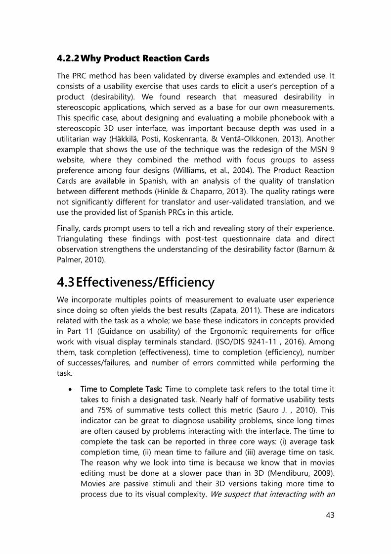
43
4.2.2 Why Product Reaction Cards
The PRC method has been validated by diverse examples and extended use. It
consists of a usability exercise that uses cards to elicit a user’s perception of a
product (desirability). We found research that measured desirability in
stereoscopic applications, which served as a base for our own measurements.
This specific case, about designing and evaluating a mobile phonebook with a
stereoscopic 3D user interface, was important because depth was used in a
utilitarian way (Häkkilä, Posti, Koskenranta, & Ventä-Olkkonen, 2013). Another
example that shows the use of the technique was the redesign of the MSN 9
website, where they combined the method with focus groups to assess
preference among four designs (Williams, et al., 2004). The Product Reaction
Cards are available in Spanish, with an analysis of the quality of translation
between different methods (Hinkle & Chaparro, 2013). The quality ratings were
not significantly different for translator and user-validated translation, and we
use the provided list of Spanish PRCs in this article.
Finally, cards prompt users to tell a rich and revealing story of their experience.
Triangulating these findings with post-test questionnaire data and direct
observation strengthens the understanding of the desirability factor (Barnum &
Palmer, 2010).
4.3 Effectiveness/Efficiency
We incorporate multiples points of measurement to evaluate user experience
since doing so often yields the best results (Zapata, 2011). These are indicators
related with the task as a whole; we base these indicators in concepts provided
in Part 11 (Guidance on usability) of the Ergonomic requirements for office
work with visual display terminals standard. (ISO/DIS 9241-11 , 2016). Among
them, task completion (effectiveness), time to completion (efficiency), number
of successes/failures, and number of errors committed while performing the
task.
Time to Complete Task: Time to complete task refers to the total time it
takes to finish a designated task. Nearly half of formative usability tests
and 75% of summative tests collect this metric (Sauro J. , 2010). This
indicator can be great to diagnose usability problems, since long times
are often caused by problems interacting with the interface. The time to
complete the task can be reported in three core ways: (i) average task
completion time, (ii) mean time to failure and (iii) average time on task.
The reason why we look into time is because we know that in movies
editing must be done at a slower pace than in 3D (Mendiburu, 2009).
Movies are passive stimuli and their 3D versions taking more time to
process due to its visual complexity. We suspect that interacting with an
44
application where depth has a utilitarian function can also result in
different time management by users.
Task Completion Success/Failure: This performance indicator logs if the
task was accomplished or not. It can also be combined with time to
complete task in order to log average failure or success time.
Number of Errors: Number of errors logs the amount of mistakes a user
makes while executing a task. Similar to past indicators, number of errors
is self-explanatory, but in a game scenario it can refer to number of
opportunities or misses to achieve an objective. In this scenario it can
refer to health or ‘lives’.
4.4 Eye Tracking Measurements
When an eye tracker is used, we have access to gaze dwell time, hit rate and
gaze sequence. The relevance of all these indicators is dependent on the case
study we are evaluating. Eye tracking is the process of measuring where a user
is looking. We will define dwell time, hit ratio and gaze sequence according to
the SMI manual (SMI, 2016):
Dwell Time: Dwell time average ms = sum (all fixations and saccades
within an AOI for all selected subjects)/number of selected subjects.
Hit Ratio: How many subjects out of the selected subjects looked at least
one time into the AOI.
Gaze Sequence: Order of gaze hits into the AOIs based on entry time.
We want to do eye-tracking because when approaching usability, an important
factor regarding a user interface is how you look at it. This can reveal cognitive
intent, interest and saliency. So while it is known that in news websites text
attracts attention before graphics, that the common behaviour is to ruthlessly
ignore details (Nielsen J. , 2000), and that in web Search Engine Result Pages
(SERPs) and other webpages eye movements resemble an F-Shaped pattern,
the question that remained was if stereoscopic depth could change our gaze
patterns. Several studies have shown how this affects shots of a movie
(Häkkinen, Kawai, Takatalo, Mitsuya, & Nyman, 2010), but our interest was more
into familiar web applications.
4.5 Further Classification of PRC
Section 4.2 introduced the construct of desirability. We said that the way we
measure this, based on similar research done in (Häkkilä, Posti, Koskenranta, &
Ventä-Olkkonen, 2013) was through Product Reaction Cards. We wanted to
have a way of classifying the terms selected by the users in order to identify the
connotation of those terms, but with 118 terms the interpretations and analysis
of these cards post experiment gets cumbersome. We looked into grouping the
45
118 terms of the Product Reaction Cards into categories that shared similar
connotations in order to more easily describe an application. This marks our
first contribution to the software development process chain in general we are
looking into.
We resort to a simple technique in user experience design: Card Sorting. This is
a method used to help design or evaluate the Information Architecture (IA) of a
system. IA refers to the art and science of organizing and labeling web sites,
intranets, online communities and software to support usability and findability.
In a more general form, according to the Information Architecture Institute, IA
is the practice of deciding how to arrange the parts of something to be
understandable (IAI, 2016).
Knowing how users group information is optimal for designing menus,
navigation, structure and labelling categories of a website. We find this type of
clustering also useful to categorize the Product Reaction Cards since the
underlying idea is grouping a set of objects in a way that objects in the same
group are more similar to each other than objects in another group. All this
from the perspective of an expert group of users. This will help understand how
users envision the organization of the presented concepts. It will allow us to
explore how they group concepts and understand their mental model. We
chose this technique because it is effective, it is quick, it is cheap, and it allowed
us to use data and methods we already had from the PRCs and it involves the
(expert) users in our processes. We get out from this process both qualitative
and quantitative results, since we are not only recording the created groupings
and generated terminology, but also the frequency items are grouped together.
A group of subject experts were commanded to group the 118 terms of the
Product Reaction Cards into different categories. The exercise comes in
response to the number of terms to be organized. It is big and no other existing
taxonomy can group the span of concepts encompassed. Also, the similarity of
certain terms make them hard to divide clearly into different categories, while
adding to the same concept the user wants to express.
We conducted a search of computer engineers, user interface (UI) and user
experience (UX) designers, mobile developers and computer scientists that had
previously work in software development. We recruited 15 users, the minimum
recommended by Nielsen (Nielsen J. , 2004) to keep an acceptable correlation
between the results and the ultimate results. All participants are professionals
related to the area of computer and software engineering, with at least 6 years
of expertise in systems/application design and development. Among the
responses we had professionals from the United Kingdom, Costa Rica, Mexico,
Spain and the United States.
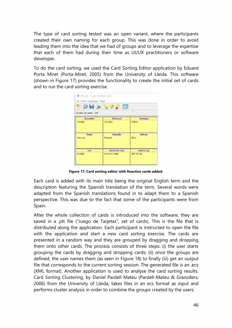
46
The type of card sorting tested was an open variant, where the participants
created their own naming for each group. This was done in order to avoid
leading them into the idea that we had of groups and to leverage the expertise
that each of them had during their time as UI/UX practitioners or software
developer.
To do the card sorting, we used the Card Sorting Editor application by Eduard
Porta Miret (Porta-Miret, 2005) from the University of Lleida. This software
(shown in Figure 17) provides the functionality to create the initial set of cards
and to run the card sorting exercise.
Figure 17: Card sorting editor with Reaction cards added.
Each card is added with its main title being the original English term and the
description featuring the Spanish translation of the term. Several words were
adapted from the Spanish translations found in to adapt them to a Spanish
perspective. This was due to the fact that some of the participants were from
Spain.
After the whole collection of cards is introduced into the software, they are
saved in a .jdt file (“Juego de Tarjetas”, set of cards). This is the file that is
distributed along the application. Each participant is instructed to open the file
with the application and start a new card sorting exercise. The cards are
presented in a random way and they are grouped by dragging and dropping
them onto other cards. The process consists of three steps: (i) the user starts
grouping the cards by dragging and dropping cards; (ii) once the groups are
defined, the user names them (as seen in Figure 18) to finally (iii) get an output
file that corresponds to the current sorting session. The generated file is an .ecs
(XML format). Another application is used to analyse the card sorting results.
Card Sorting Clustering, by Daniel Pardell Mateu (Pardell-Mateu & Granollers,
2006) from the University of Lleida, takes files in an ecs format as input and
performs cluster analysis in order to combine the groups created by the users.
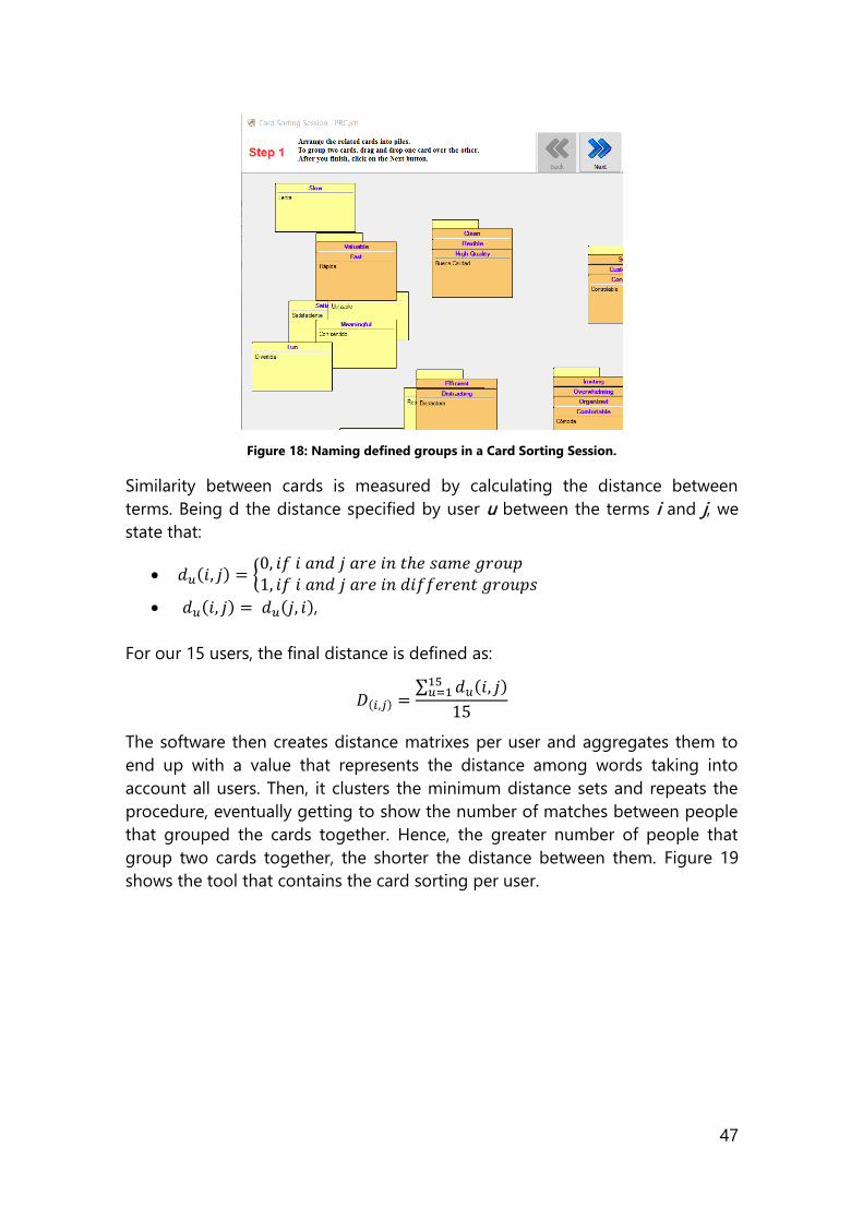
47
Figure 18: Naming defined groups in a Card Sorting Session.
Similarity between cards is measured by calculating the distance between
terms. Being d the distance specified by user u between the terms i and j, we
state that:
𝑑𝑢(𝑖, 𝑗) = {0, 𝑖𝑓 𝑖 𝑎𝑛𝑑 𝑗 𝑎𝑟𝑒 𝑖𝑛 𝑡ℎ𝑒 𝑠𝑎𝑚𝑒 𝑔𝑟𝑜𝑢𝑝 1, 𝑖𝑓 𝑖 𝑎𝑛𝑑 𝑗 𝑎𝑟𝑒 𝑖𝑛 𝑑𝑖𝑓𝑓𝑒𝑟𝑒𝑛𝑡 𝑔𝑟𝑜𝑢𝑝𝑠
𝑑𝑢(𝑖, 𝑗) = 𝑑𝑢(𝑗, 𝑖),
For our 15 users, the final distance is defined as:
𝐷(𝑖,𝑗) =∑ 𝑑𝑢(𝑖, 𝑗)15
𝑢=1
15
The software then creates distance matrixes per user and aggregates them to
end up with a value that represents the distance among words taking into
account all users. Then, it clusters the minimum distance sets and repeats the
procedure, eventually getting to show the number of matches between people
that grouped the cards together. Hence, the greater number of people that
group two cards together, the shorter the distance between them. Figure 19
shows the tool that contains the card sorting per user.
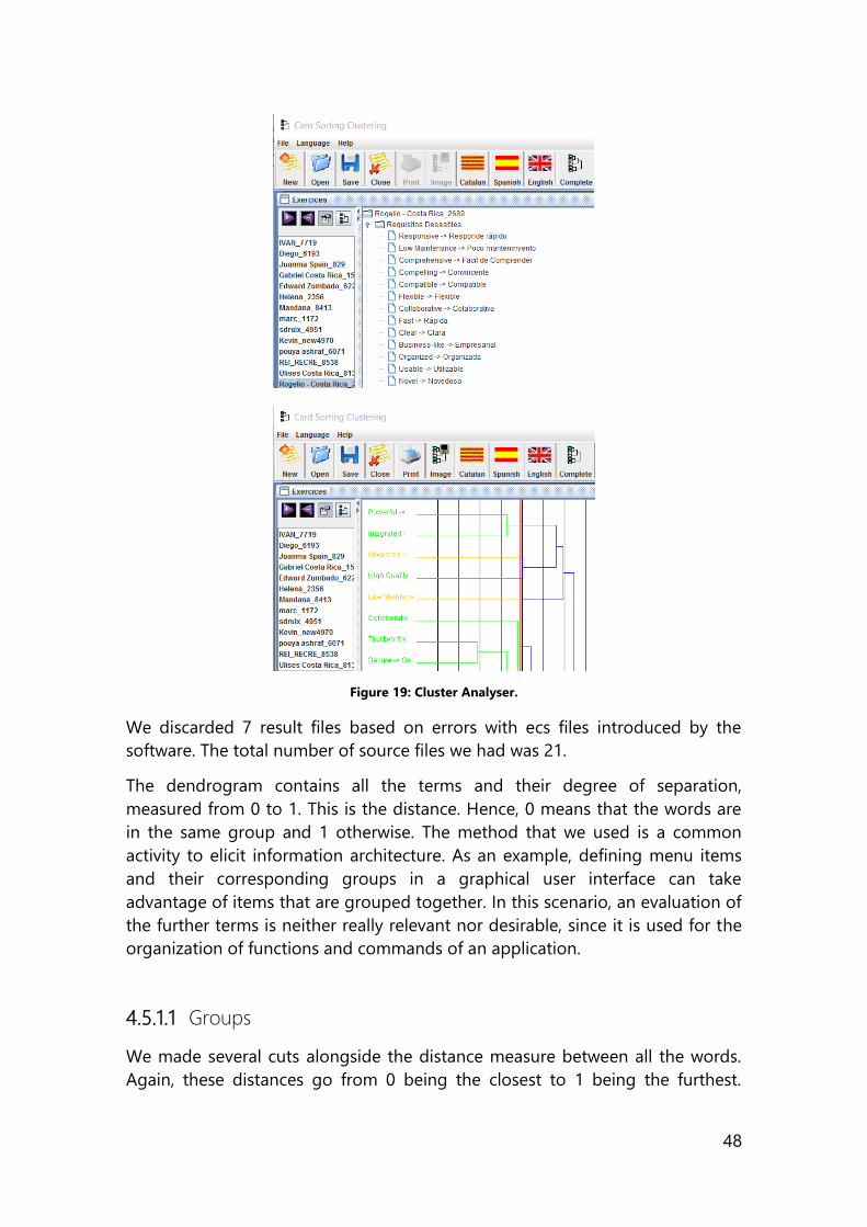
48
Figure 19: Cluster Analyser.
We discarded 7 result files based on errors with ecs files introduced by the
software. The total number of source files we had was 21.
The dendrogram contains all the terms and their degree of separation,
measured from 0 to 1. This is the distance. Hence, 0 means that the words are
in the same group and 1 otherwise. The method that we used is a common
activity to elicit information architecture. As an example, defining menu items
and their corresponding groups in a graphical user interface can take
advantage of items that are grouped together. In this scenario, an evaluation of
the further terms is neither really relevant nor desirable, since it is used for the
organization of functions and commands of an application.
4.5.1.1 Groups
We made several cuts alongside the distance measure between all the words.
Again, these distances go from 0 being the closest to 1 being the furthest.
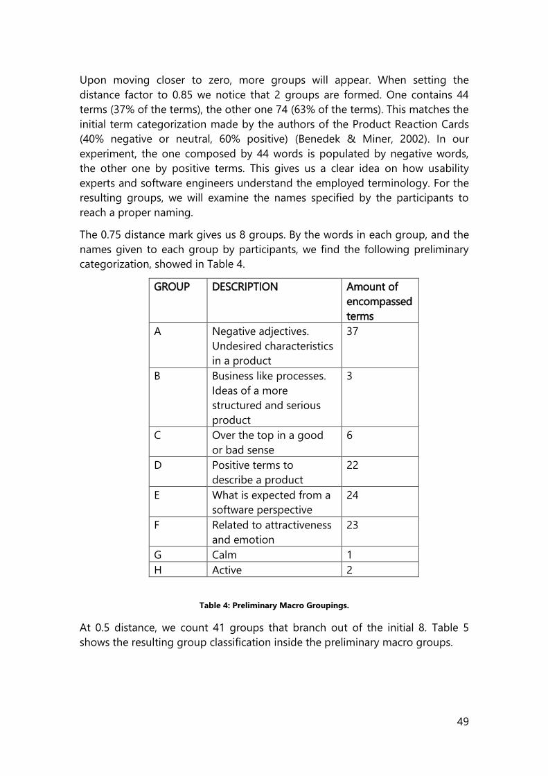
49
Upon moving closer to zero, more groups will appear. When setting the
distance factor to 0.85 we notice that 2 groups are formed. One contains 44
terms (37% of the terms), the other one 74 (63% of the terms). This matches the
initial term categorization made by the authors of the Product Reaction Cards
(40% negative or neutral, 60% positive) (Benedek & Miner, 2002). In our
experiment, the one composed by 44 words is populated by negative words,
the other one by positive terms. This gives us a clear idea on how usability
experts and software engineers understand the employed terminology. For the
resulting groups, we will examine the names specified by the participants to
reach a proper naming.
The 0.75 distance mark gives us 8 groups. By the words in each group, and the
names given to each group by participants, we find the following preliminary
categorization, showed in Table 4.
GROUP DESCRIPTION Amount of
encompassed
terms
A Negative adjectives.
Undesired characteristics
in a product
37
B Business like processes.
Ideas of a more
structured and serious
product
3
C Over the top in a good
or bad sense
6
D Positive terms to
describe a product
22
E What is expected from a
software perspective
24
F Related to attractiveness
and emotion
23
G Calm 1
H Active 2
Table 4: Preliminary Macro Groupings.
At 0.5 distance, we count 41 groups that branch out of the initial 8. Table 5
shows the resulting group classification inside the preliminary macro groups.
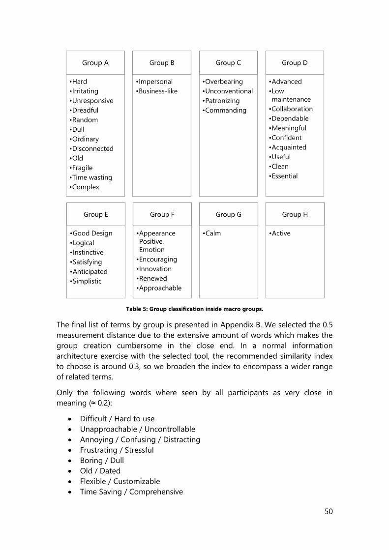
50
Table 5: Group classification inside macro groups.
The final list of terms by group is presented in Appendix B. We selected the 0.5
measurement distance due to the extensive amount of words which makes the
group creation cumbersome in the close end. In a normal information
architecture exercise with the selected tool, the recommended similarity index
to choose is around 0.3, so we broaden the index to encompass a wider range
of related terms.
Only the following words where seen by all participants as very close in
meaning (≈ 0.2):
Difficult / Hard to use
Unapproachable / Uncontrollable
Annoying / Confusing / Distracting
Frustrating / Stressful
Boring / Dull
Old / Dated
Flexible / Customizable
Time Saving / Comprehensive
Group A
•Hard
•Irritating
•Unresponsive
•Dreadful
•Random
•Dull
•Ordinary
•Disconnected
•Old
•Fragile
•Time wasting
•Complex
Group B
•Impersonal
•Business-like
Group C
•Overbearing
•Unconventional
•Patronizing
•Commanding
Group D
•Advanced
•Low
maintenance
•Collaboration
•Dependable
•Meaningful
•Confident
•Acquainted
•Useful
•Clean
•Essential
Group E
•Good Design
•Logical
•Instinctive
•Satisfying
•Anticipated
•Simplistic
Group F
•Appearance
Positive,
Emotion
•Encouraging
•Innovation
•Renewed
•Approachable
Group G
•Calm
Group H
•Active
51
Effective / Efficient
Appealing / Attractive
Fun / Entertaining
Engaging / Enthusiastic
The most complicated words to analyse by users were: impersonal, patronizing,
calm, unconventional, meaningful, satisfying, simplistic.
The term “calm” is the only word that was distant from all other words.
Therefore, it is feature as the only high level group that contains only one term.
We are using this classification in our experiments when applying the Microsoft
Product Reactions Cards to better analyse what the user is communicating. The
similarity in meaning and connotations of a set of words, even among a
controlled focus group of final users of any software can be large. Therefore,
having a tool that allows us to aggregate these potentially similar meanings is
of great value towards enhancing the core experience of a product.
Additionally, plotting the group results in a radar chart provides a
straightforward summary of how users visualize the application. Figures 35 and
46 are examples of the use of this.
The 118 classified terms are shown in Appendix B. Classification of Product
Reaction Cards.
4.6 Summary of the chapter
This chapter starts by exploring the concept of User Experience (UX) and how
this construct is defined by the ISO. Noteworthy is the fact that UX is a concept
that consists of many other constructs, like Utility, Usability, Desirability and
Brand Experience. User Experiences goes beyond the question “is software
usable?”
The relevant constructs that we will measure in our experiments are Usability,
Desirability and Effectiveness/Efficiency. Usability refers to the extent which a
system, product or service can be used by specified users to achieve specified
goals with effectiveness, efficiency and satisfaction in a specified context of use.
We are measuring it using the System Usability Scale defined by John Brooke in
1986.
Desirability provides a layer of qualitative impact of the system. It concerns how
a product “looks and feels”. It is a characteristic that we look for when we
develop experiences, yet its subjective nature makes it difficult to quantify. This
goes beyond the “is the product usable”. To measure desirability, we will use
Microsoft Production Reaction Cards, a method defined by Trish and Miner in
2002.

52
Efficiency and effectiveness, are also defined, tied to the task in hand, by task
completion, number of errors and time to task completion. Other
measurements related to eye tracking and gaze patterns are defined as well.
Finally, our contribution in this chapter, a clustering exercise over the Product
Reaction Cards, that results in 8 groups and 41 subgroups that allow a better
qualitative analysis of the 118 terms and the ones selected by the user. The
classification can be found in the Appendixes section of the present work.
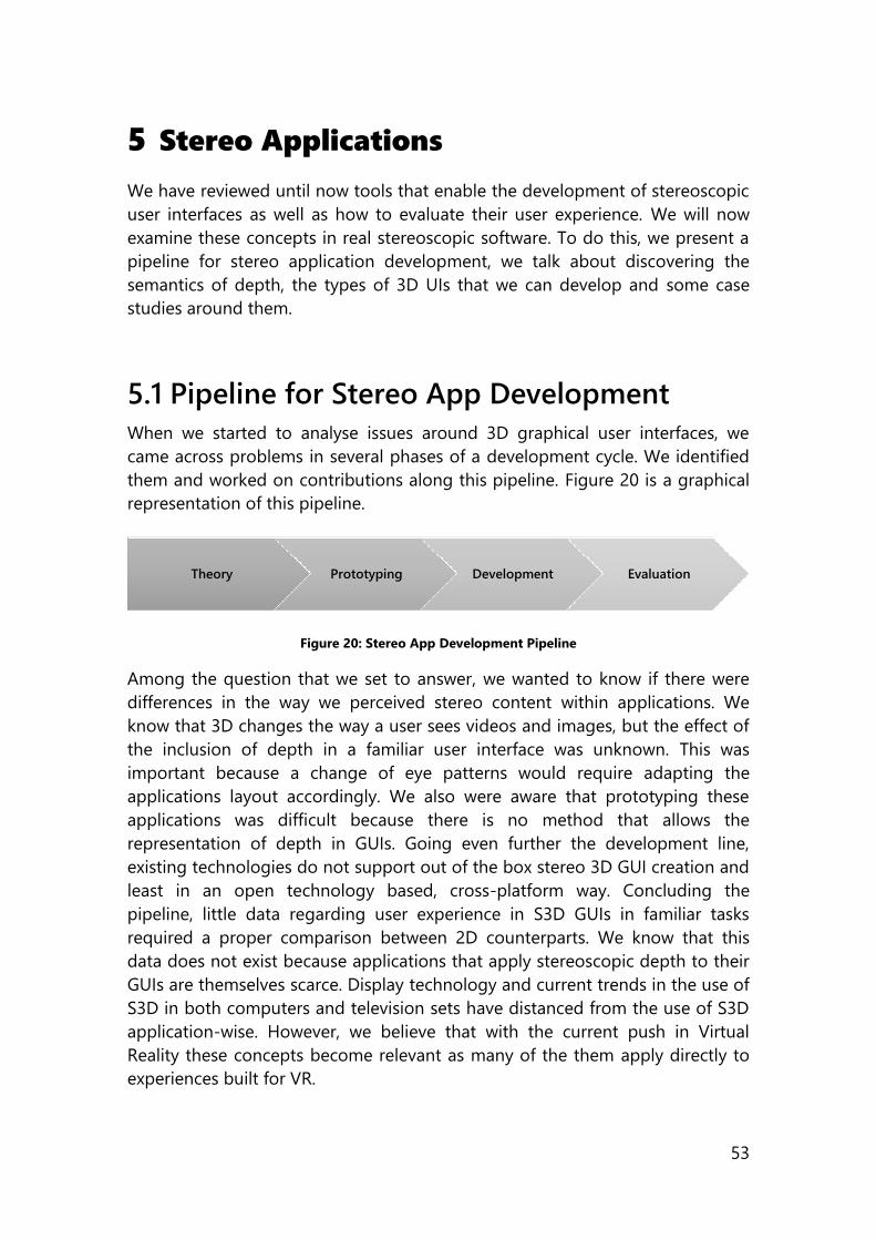
53
5 Stereo Applications
We have reviewed until now tools that enable the development of stereoscopic
user interfaces as well as how to evaluate their user experience. We will now
examine these concepts in real stereoscopic software. To do this, we present a
pipeline for stereo application development, we talk about discovering the
semantics of depth, the types of 3D UIs that we can develop and some case
studies around them.
5.1 Pipeline for Stereo App Development
When we started to analyse issues around 3D graphical user interfaces, we
came across problems in several phases of a development cycle. We identified
them and worked on contributions along this pipeline. Figure 20 is a graphical
representation of this pipeline.
Figure 20: Stereo App Development Pipeline
Among the question that we set to answer, we wanted to know if there were
differences in the way we perceived stereo content within applications. We
know that 3D changes the way a user sees videos and images, but the effect of
the inclusion of depth in a familiar user interface was unknown. This was
important because a change of eye patterns would require adapting the
applications layout accordingly. We also were aware that prototyping these
applications was difficult because there is no method that allows the
representation of depth in GUIs. Going even further the development line,
existing technologies do not support out of the box stereo 3D GUI creation and
least in an open technology based, cross-platform way. Concluding the
pipeline, little data regarding user experience in S3D GUIs in familiar tasks
required a proper comparison between 2D counterparts. We know that this
data does not exist because applications that apply stereoscopic depth to their
GUIs are themselves scarce. Display technology and current trends in the use of
S3D in both computers and television sets have distanced from the use of S3D
application-wise. However, we believe that with the current push in Virtual
Reality these concepts become relevant as many of the them apply directly to
experiences built for VR.
Theory Prototyping Development Evaluation
54
When creating this pipeline, we followed three principles of design that ensured
it would be designed for usability; our contributions should be able to
seamlessly mix with a process that incorporated an early focus on users and
tasks, allowed for empirical measurement of the created interfaces and blend
with an iterative approach (Gould & Lewis, 1985).
Another different subject, yet one related with the pipeline, is how do we make
use of this depth. Following we discuss on the possible semantics of depth.
5.2 Discovering the Semantics of Depth
As I discussed in section 2.5, in terms of storytelling, 3D brings a whole new
toolset to film directors. There, the important thing is that the film interprets
reality in a way that is more suitable for the story. Similarly, there are many
ways in which we can interpret depth presented in an application. They vary
from task to task. Examples span from visualization of air traffic control (Dang,
Le, & Tavanti, 2003) to real-time 3D GPU Simulation (NVIDIA, 2016). We have
chosen to focus on utilising depth to imply importance, rating and hierarchy.
The use cases presented in the following section 5.4 measure the impact of
depth in usability and desirability while having different utilitarian applications.
The following list shows how we use depth in our study cases.
Rating importance: Elements closer to the user have higher relevance.
Selecting/Highlighting elements: Visual cue to selecting a specific
element.
Grouping elements: elements that belong to different positions in the z
axis belong to different groups.
Enhancing aesthetic: models of elements can benefit from the 3D effect.
Guiding the user: we use saliency to try to lure the user towards certain
graphic elements.
5.3 Types of 3D UIs
We started working with the idea of differentiating the applications we would
build from the type of interfaces that certain games had. With this we mean
that the types of graphical user interface we want are neither spatial nor
volumetric, like most modern videogames. The main reason for this was that
our main objective has been to enhance “traditional” GUIs with depth. These
traditional applications spawn across more day to day tasks, like word
processing, painting, information visualization, and retailing, to name a few
55
examples. We had to deal with an event-driven model and think about how to
introduce depth to these interfaces. We came up with a terminology that would
allow us to identify a type of GUI we wanted to build, that allowed us to refer to
the type of stereoscopic depth we would apply to it. We now discuss discrete
and analog S3D GUIs and what have we developed to create them.
5.3.1 Flat or discrete
This type of graphical user interface features interface elements that are flat. It
can contain traditional UI elements like buttons, dropdown boxes, checkboxes,
menus, lists, images but positions them in different discrete layers of the z axis.
Generally, these layers are defined, equally separated and then populated with
elements following a semantic grouping. The only technique that creates depth
is the one based on applying different offsets to each image generated for each
eye. As examples, we can think of the way we enhanced a search engine result
page with depth, or how we set the layout for the cursor and toolbox in the
S3Doodle web application. This kind of user interface works best for elements
that should not be projected in a perspective way. It is also tightly coupled with
the kind of development platform that is chosen. Among these platforms we
can cite WPF, HTML5 Canvas and any other framework that works by shifting
elements horizontally in each view. This also translates into a more traditional
event-driven model based on the programing platform that is used.
5.3.2 Analog/Open Space
Analog GUIs introduce models to the Z axis. These 3D models are not flat and
mix with the flat elements on the UI. In a similar manner, the 3D models are not
restrained to specific layers, and can occupy a volume on the UI. This means
that the GUI must have a 3D mechanism to manage a scene which represents
the space on which the UI elements are positioned. This changes the way the
coding is done for this applications into a more game-like environment, and
brings along collision detection, lighting and the perspective projection. Based
on our experience with the coding platforms available to implement this kind of
interfaces, we recommend an environment capable of working with a 3D scene
and dual viewports that render images from different cameras.
5.3.3 Limitations
The limitations of all these types of interfaces are that they do not represent a
real 3D environment. We are working with stereoscopic content, so we are
limited to two different views of the content.

56
5.4 Case Studies
5.4.1 Eye Tracking Preliminary Test
For exploratory purposes with eye tracking (ET), we performed in conjunction
with Anna Maszerowska an experiment to analyse how the presence/absence of
color in stereoscopic video would affect the deployment of attention. For this,
we selected several clips from the film “Transformers Dark of the Moon” (Bay,
2011) in Full HD and defined several areas of interest (AOI) based on color. We
gave the users the task to watch these clips and explain the plot. The next
figures show the types of clips that we chose for the task. Figure 21 focuses on
near movement and action. Figure 22 pays attention to the bright red color on
the robot’s eyes, and Figure 23 focuses on foreground and (mountain)
background elements.
Figure 21: First clip of ET test.
We tested 10 participants in an in between subjects, counterbalanced
experiment. We measured gaze dwell time in specific areas of interest (AOI)
seen in Figures 19, 20 and 21, of approximately 3 seconds each.
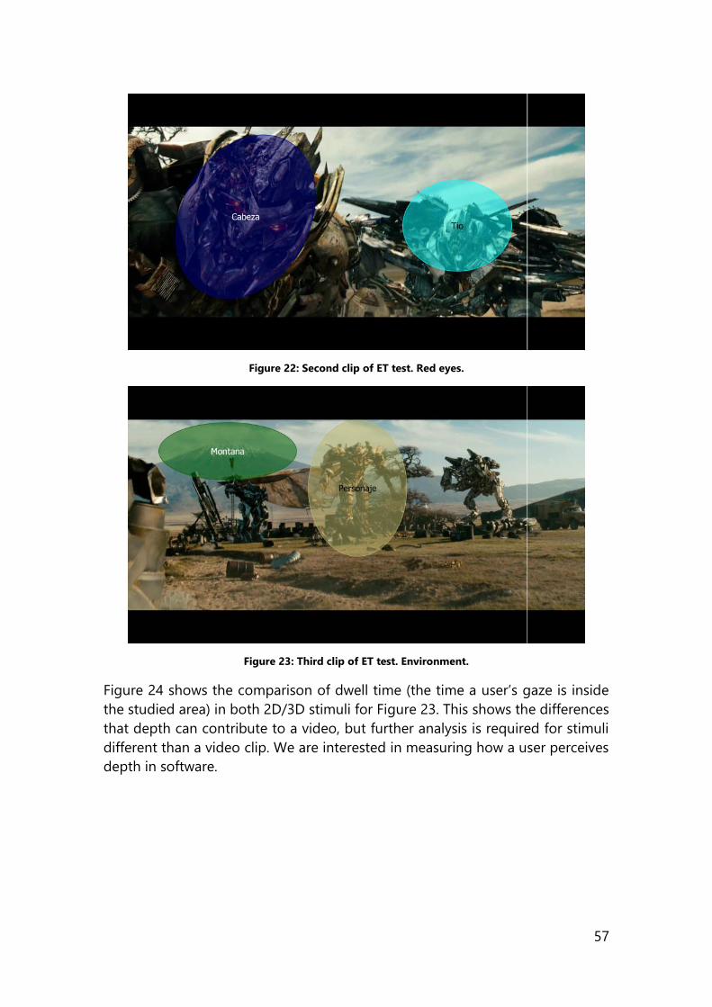
57
Figure 22: Second clip of ET test. Red eyes.
Figure 23: Third clip of ET test. Environment.
Figure 24 shows the comparison of dwell time (the time a user’s gaze is inside
the studied area) in both 2D/3D stimuli for Figure 23. This shows the differences
that depth can contribute to a video, but further analysis is required for stimuli
different than a video clip. We are interested in measuring how a user perceives
depth in software.
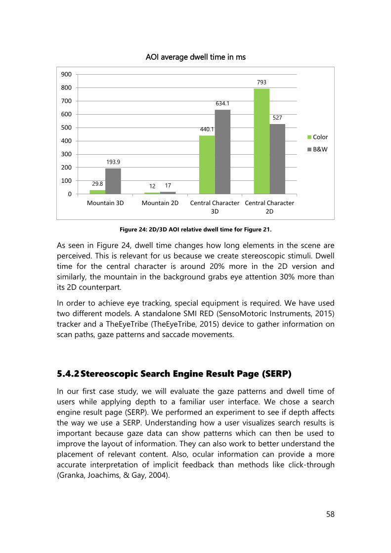
58
AOI average dwell time in ms
Figure 24: 2D/3D AOI relative dwell time for Figure 21.
As seen in Figure 24, dwell time changes how long elements in the scene are
perceived. This is relevant for us because we create stereoscopic stimuli. Dwell
time for the central character is around 20% more in the 2D version and
similarly, the mountain in the background grabs eye attention 30% more than
its 2D counterpart.
In order to achieve eye tracking, special equipment is required. We have used
two different models. A standalone SMI RED (SensoMotoric Instruments, 2015)
tracker and a TheEyeTribe (TheEyeTribe, 2015) device to gather information on
scan paths, gaze patterns and saccade movements.
5.4.2 Stereoscopic Search Engine Result Page (SERP)
In our first case study, we will evaluate the gaze patterns and dwell time of
users while applying depth to a familiar user interface. We chose a search
engine result page (SERP). We performed an experiment to see if depth affects
the way we use a SERP. Understanding how a user visualizes search results is
important because gaze data can show patterns which can then be used to
improve the layout of information. They can also work to better understand the
placement of relevant content. Also, ocular information can provide a more
accurate interpretation of implicit feedback than methods like click-through
(Granka, Joachims, & Gay, 2004).
29.8 12
440.1
793
193.9
17
634.1
527
0
100
200
300
400
500
600
700
800
900
Mountain 3D Mountain 2D Central Character3D
Central Character2D
Color
B&W
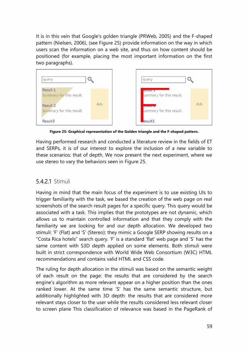
59
It is in this vein that Google's golden triangle (PRWeb, 2005) and the F-shaped
pattern (Nielsen, 2006), (see Figure 25) provide information on the way in which
users scan the information on a web site, and thus on how content should be
positioned (for example, placing the most important information on the first
two paragraphs).
Figure 25: Graphical representation of the Golden triangle and the F-shaped pattern.
Having performed research and conducted a literature review in the fields of ET
and SERPs, it is of our interest to explore the inclusion of a new variable to
these scenarios: that of depth. We now present the next experiment, where we
use stereo to vary the behaviors seen in Figure 25.
5.4.2.1 Stimuli
Having in mind that the main focus of the experiment is to use existing UIs to
trigger familiarity with the task, we based the creation of the web page on real
screenshots of the search result pages for a specific query. This query would be
associated with a task. This implies that the prototypes are not dynamic, which
allows us to maintain controlled information and that they comply with the
familiarity we are looking for and our depth allocation. We developed two
stimuli: ‘F’ (Flat) and ‘S’ (Stereo): they mimic a Google SERP showing results on a
“Costa Rica hotels” search query. ‘F’ is a standard ‘flat’ web page and ‘S’ has the
same content with S3D depth applied on some elements. Both stimuli were
built in strict correspondence with World Wide Web Consortium (W3C) HTML
recommendations and contains valid HTML and CSS code.
The ruling for depth allocation in the stimuli was based on the semantic weight
of each result on the page: the results that are considered by the search
engine’s algorithm as more relevant appear on a higher position than the ones
ranked lower. At the same time ‘S’ has the same semantic structure, but
additionally highlighted with 3D depth: the results that are considered more
relevant stays closer to the user while the results considered less relevant closer
to screen plane This classification of relevance was based in the PageRank of
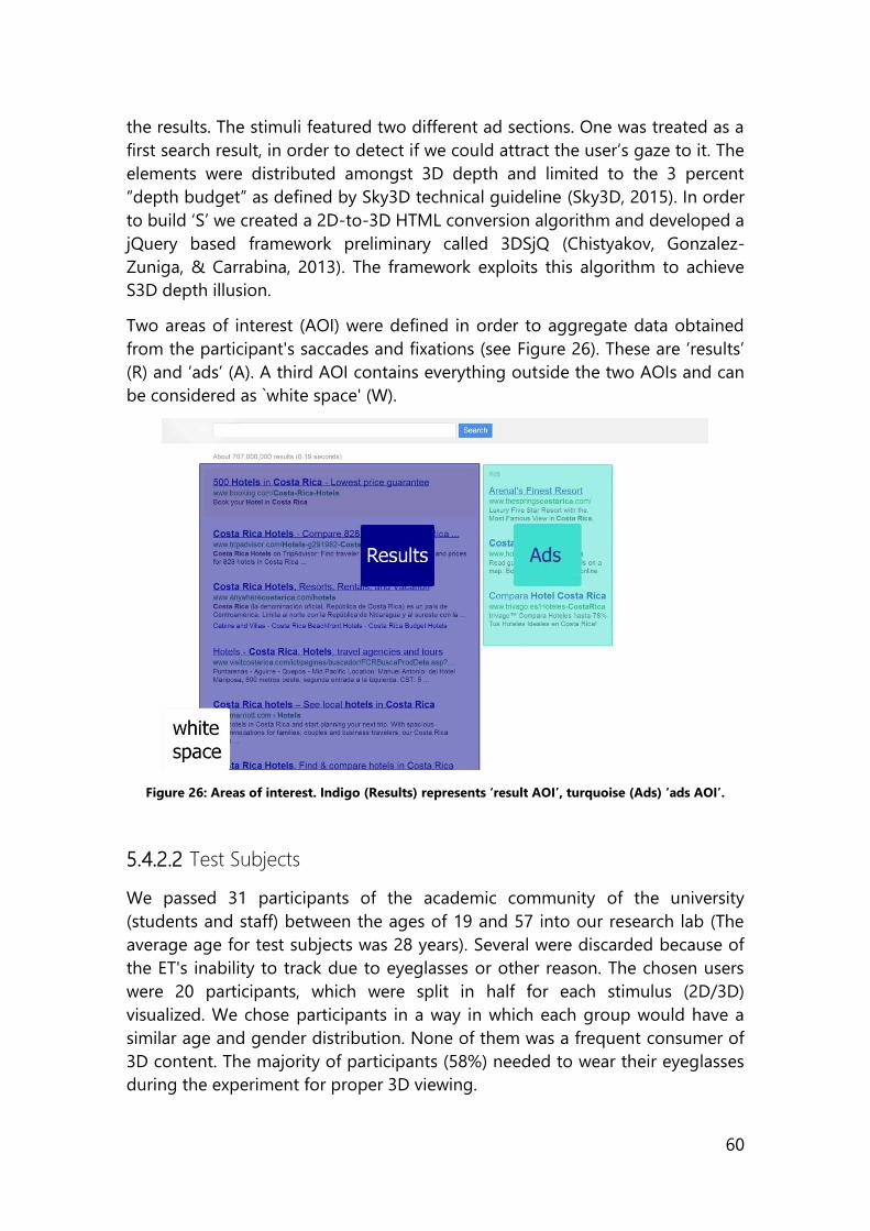
60
the results. The stimuli featured two different ad sections. One was treated as a
first search result, in order to detect if we could attract the user’s gaze to it. The
elements were distributed amongst 3D depth and limited to the 3 percent
“depth budget” as defined by Sky3D technical guideline (Sky3D, 2015). In order
to build ‘S’ we created a 2D-to-3D HTML conversion algorithm and developed a
jQuery based framework preliminary called 3DSjQ (Chistyakov, Gonzalez-
Zuniga, & Carrabina, 2013). The framework exploits this algorithm to achieve
S3D depth illusion.
Two areas of interest (AOI) were defined in order to aggregate data obtained
from the participant's saccades and fixations (see Figure 26). These are ‘results’
(R) and ‘ads’ (A). A third AOI contains everything outside the two AOIs and can
be considered as `white space' (W).
Figure 26: Areas of interest. Indigo (Results) represents ‘result AOI’, turquoise (Ads) ‘ads AOI’.
5.4.2.2 Test Subjects
We passed 31 participants of the academic community of the university
(students and staff) between the ages of 19 and 57 into our research lab (The
average age for test subjects was 28 years). Several were discarded because of
the ET's inability to track due to eyeglasses or other reason. The chosen users
were 20 participants, which were split in half for each stimulus (2D/3D)
visualized. We chose participants in a way in which each group would have a
similar age and gender distribution. None of them was a frequent consumer of
3D content. The majority of participants (58%) needed to wear their eyeglasses
during the experiment for proper 3D viewing.
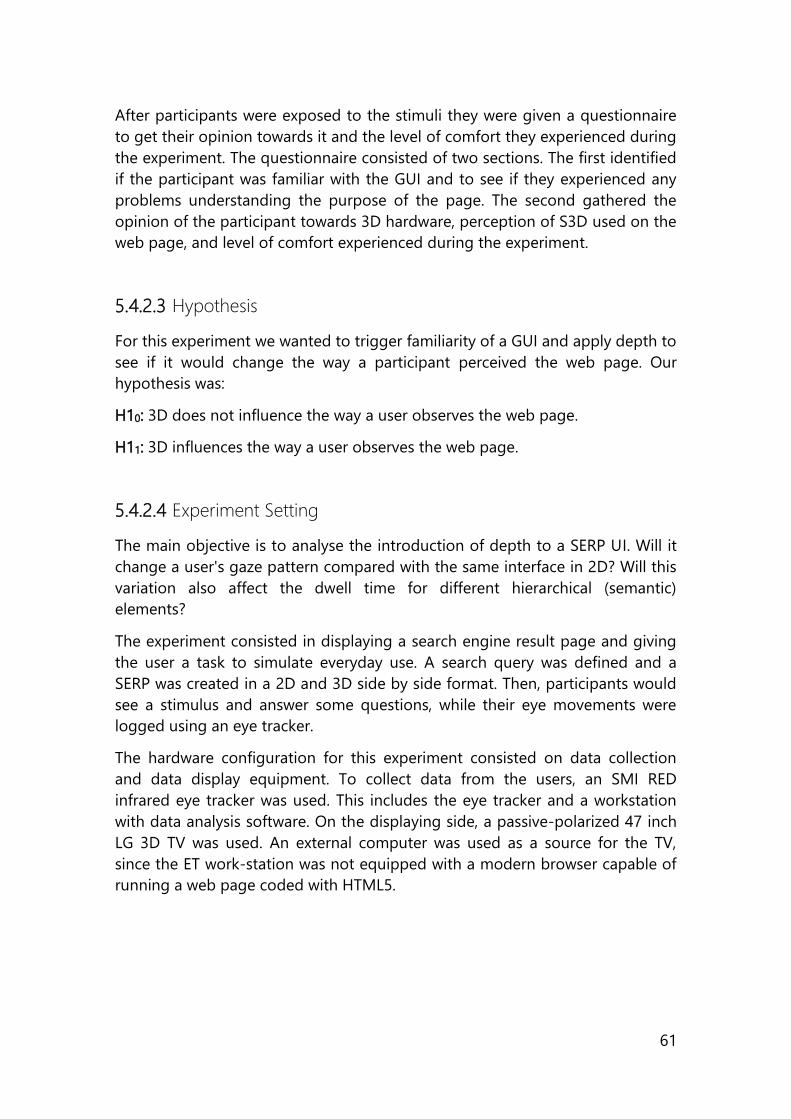
61
After participants were exposed to the stimuli they were given a questionnaire
to get their opinion towards it and the level of comfort they experienced during
the experiment. The questionnaire consisted of two sections. The first identified
if the participant was familiar with the GUI and to see if they experienced any
problems understanding the purpose of the page. The second gathered the
opinion of the participant towards 3D hardware, perception of S3D used on the
web page, and level of comfort experienced during the experiment.
5.4.2.3 Hypothesis
For this experiment we wanted to trigger familiarity of a GUI and apply depth to
see if it would change the way a participant perceived the web page. Our
hypothesis was:
H10: 3D does not influence the way a user observes the web page.
H11: 3D influences the way a user observes the web page.
5.4.2.4 Experiment Setting
The main objective is to analyse the introduction of depth to a SERP UI. Will it
change a user's gaze pattern compared with the same interface in 2D? Will this
variation also affect the dwell time for different hierarchical (semantic)
elements?
The experiment consisted in displaying a search engine result page and giving
the user a task to simulate everyday use. A search query was defined and a
SERP was created in a 2D and 3D side by side format. Then, participants would
see a stimulus and answer some questions, while their eye movements were
logged using an eye tracker.
The hardware configuration for this experiment consisted on data collection
and data display equipment. To collect data from the users, an SMI RED
infrared eye tracker was used. This includes the eye tracker and a workstation
with data analysis software. On the displaying side, a passive-polarized 47 inch
LG 3D TV was used. An external computer was used as a source for the TV,
since the ET work-station was not equipped with a modern browser capable of
running a web page coded with HTML5.
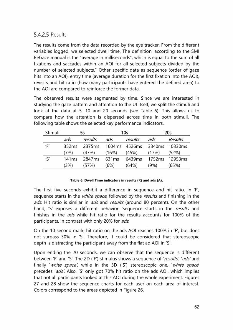
62
5.4.2.5 Results
The results come from the data recorded by the eye tracker. From the different
variables logged, we selected dwell time. The definition, according to the SMI
BeGaze manual is the “average in milliseconds”, which is equal to the sum of all
fixations and saccades within an AOI for all selected subjects divided by the
number of selected subjects.” Other specific data as sequence (order of gaze
hits into an AOI), entry time (average duration for the first fixation into the AOI),
revisits and hit ratio (how many participants have entered the defined area) to
the AOI are compared to reinforce the former data.
The observed results were segmented by time. Since we are interested in
studying the gaze pattern and attention to the UI itself, we split the stimuli and
look at the data at 5, 10 and 20 seconds (see Table 6). This allows us to
compare how the attention is dispersed across time in both stimuli. The
following table shows the selected key performance indicators.
Stimuli 5s 10s 20s
ads results ads results ads Results
‘F’ 352ms
(7%)
2375ms
(47%)
1604ms
(16%)
4526ms
(45%)
3340ms
(17%)
10330ms
(52%)
‘S’ 141ms
(3%)
2847ms
(57%)
631ms
(6%)
6439ms
(64%)
1752ms
(9%)
12953ms
(65%)
Table 6: Dwell Time indicators in results (R) and ads (A).
The first five seconds exhibit a difference in sequence and hit ratio. In ‘F’,
sequence starts in the white space, followed by the results and finishing in the
ads. Hit ratio is similar in ads and results (around 80 percent). On the other
hand, ‘S’ exposes a different behavior: Sequence starts in the results and
finishes in the ads while hit ratio for the results accounts for 100% of the
participants, in contrast with only 20% for ads.
On the 10 second mark, hit ratio on the ads AOI reaches 100% in ‘F’, but does
not surpass 30% in ‘S’. Therefore, it could be considered that stereoscopic
depth is distracting the participant away from the flat ad AOI in ‘S’.
Upon ending the 20 seconds, we can observe that the sequence is different
between ‘F’ and ‘S’: The 2D (‘F’) stimulus shows a sequence of ‘results’, ‘ads’ and
finally ‘white space’, while in the 3D (‘S’) stereoscopic one, ‘white space’
precedes ‘ads’. Also, ‘S’ only got 70% hit ratio on the ads AOI, which implies
that not all participants looked at this AOI during the whole experiment. Figures
27 and 28 show the sequence charts for each user on each area of interest.
Colors correspond to the areas depicted in Figure 26.
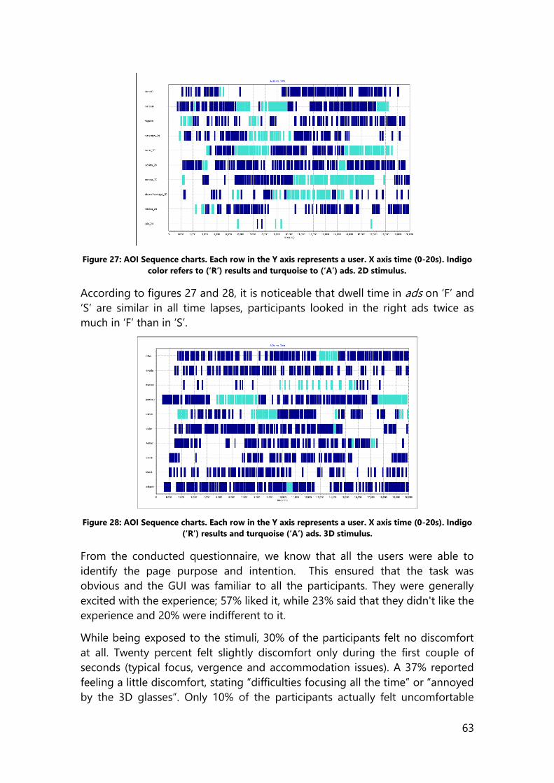
63
Figure 27: AOI Sequence charts. Each row in the Y axis represents a user. X axis time (0-20s). Indigo
color refers to (‘R’) results and turquoise to (‘A’) ads. 2D stimulus.
According to figures 27 and 28, it is noticeable that dwell time in ads on ‘F’ and
‘S’ are similar in all time lapses, participants looked in the right ads twice as
much in ‘F’ than in ‘S’.
Figure 28: AOI Sequence charts. Each row in the Y axis represents a user. X axis time (0-20s). Indigo
(‘R’) results and turquoise (‘A’) ads. 3D stimulus.
From the conducted questionnaire, we know that all the users were able to
identify the page purpose and intention. This ensured that the task was
obvious and the GUI was familiar to all the participants. They were generally
excited with the experience; 57% liked it, while 23% said that they didn't like the
experience and 20% were indifferent to it.
While being exposed to the stimuli, 30% of the participants felt no discomfort
at all. Twenty percent felt slightly discomfort only during the first couple of
seconds (typical focus, vergence and accommodation issues). A 37% reported
feeling a little discomfort, stating “difficulties focusing all the time” or “annoyed
by the 3D glasses”. Only 10% of the participants actually felt uncomfortable
64
during the experience. The rest of the participants found it hard to tell how they
felt.
Nonetheless, the majority of participants said that they would consider using
3D websites for browsing through any type content browsing only pages
containing media content; 27% of the participants said that they would not use
3D for web browsing at all and 10% of the participants said that they would
consider using 3D web if no glasses were required.
The overwhelming majority of the participants answered that 3D influenced the
content on the page; 60% thought it was a positive influence. On the other
hand, 10% said that 3D influence was a negative one, making the text hard to
scan or read. Twenty-three percent said that 3D did not influence the content
on the page in any way. The rest of the participants found hard to tell if 3D
influenced the content or not.
Overall, we noticed a higher dispersion, longer times to gaze through the
contents of a page and altered gaze order. This corroborates the different
viewing pattern in 3D software, important since it impacts effectiveness and
efficiency in the applications. Figure 29 and 30 show the aforementioned
dispersion. Not only does it clearly show a much higher dispersion on the
stereoscopic version of the stimulus, it also shows how the F shaped pattern is
lost in this same version. Another thing to note in Figure 30 is how the edges of
each div in the html that represents a result attract visual attention, which is one
of the reasons for the higher dispersion of gaze as well.
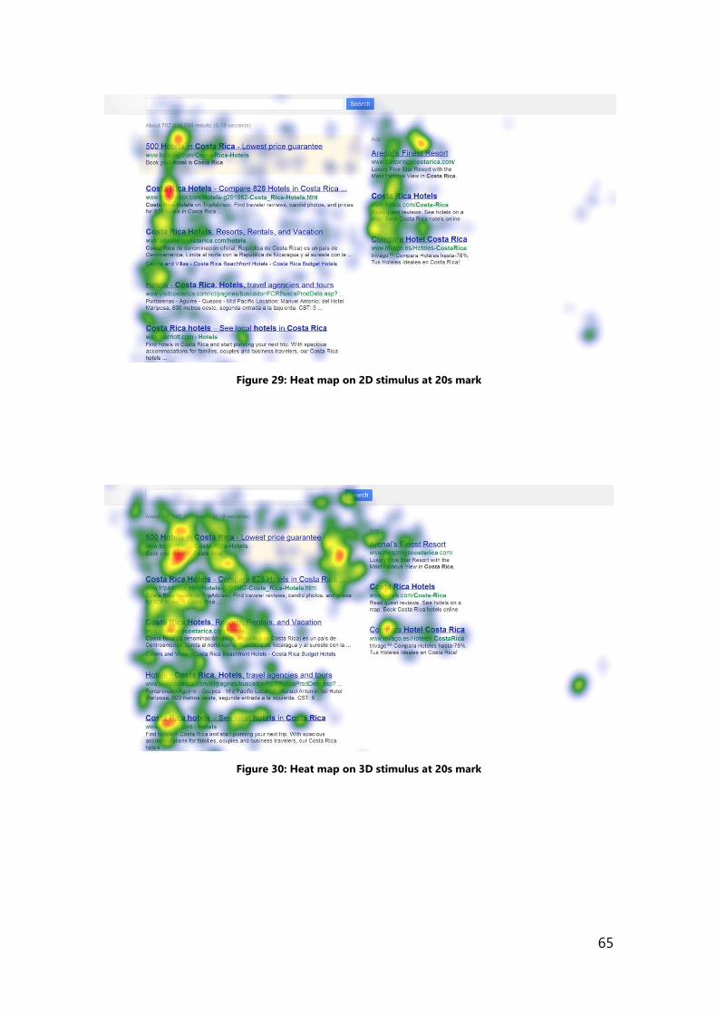
65
Figure 29: Heat map on 2D stimulus at 20s mark
Figure 30: Heat map on 3D stimulus at 20s mark
66
5.4.3 Stereo 3D Memory Game
“Pairs” is a card game where cards are laid down and every turn two are flipped
face up. The objective of the game is to turn over pairs of matching cards. This
application is an implementation of a solitaire Pairs card game with 12
opportunities to match all 6 pairs. Our interest here is to compare time to
completion and number of mistakes made by users between both 2D and S3D
versions of the game (González-Zúñiga, Acuña-Silvera, Martí-Godía, &
Carrabina, 2016).
5.4.3.1 Stimuli
Figure 31: S3D Memory game
The utilized stimulus for this experiment is a stereoscopic 3D Memory Game
developed by Acuña (Acuña, 2015). The game can be seen in Figure 31. This
application uses depth to highlight selected cards and to indicate pairs that
have been found. This application is web based and was developed using the
canv.3d tool presented in section 3.1.
5.4.3.2 Test Subjects
We recruited 40 test subjects which each played the game in 2D and 3D. We
got 80 records of users playing the game. Their age mean is 28.25 years old.
They are members of the academic community of the Autonomous University
of Barcelona. We queried participants for their previous experiences with 3D
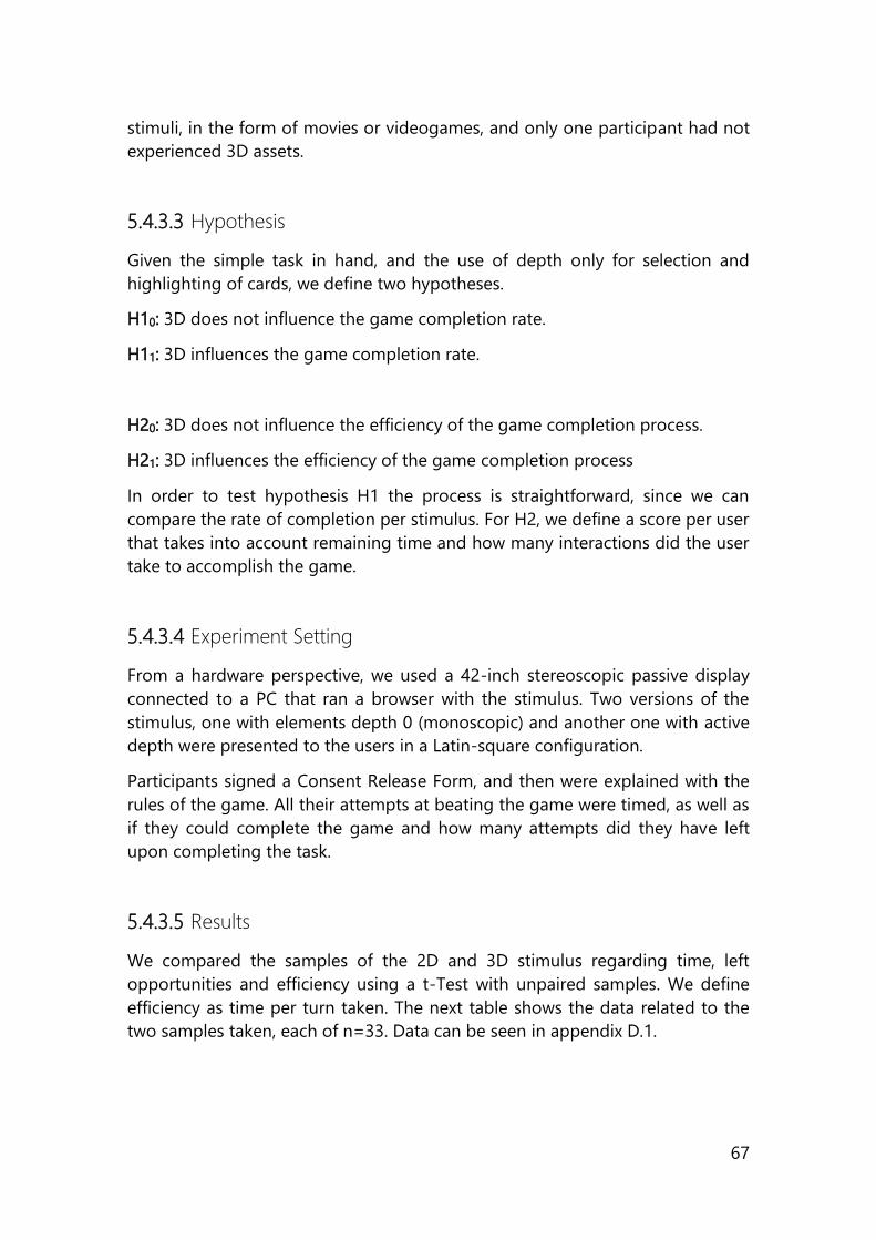
67
stimuli, in the form of movies or videogames, and only one participant had not
experienced 3D assets.
5.4.3.3 Hypothesis
Given the simple task in hand, and the use of depth only for selection and
highlighting of cards, we define two hypotheses.
H10: 3D does not influence the game completion rate.
H11: 3D influences the game completion rate.
H20: 3D does not influence the efficiency of the game completion process.
H21: 3D influences the efficiency of the game completion process
In order to test hypothesis H1 the process is straightforward, since we can
compare the rate of completion per stimulus. For H2, we define a score per user
that takes into account remaining time and how many interactions did the user
take to accomplish the game.
5.4.3.4 Experiment Setting
From a hardware perspective, we used a 42-inch stereoscopic passive display
connected to a PC that ran a browser with the stimulus. Two versions of the
stimulus, one with elements depth 0 (monoscopic) and another one with active
depth were presented to the users in a Latin-square configuration.
Participants signed a Consent Release Form, and then were explained with the
rules of the game. All their attempts at beating the game were timed, as well as
if they could complete the game and how many attempts did they have left
upon completing the task.
5.4.3.5 Results
We compared the samples of the 2D and 3D stimulus regarding time, left
opportunities and efficiency using a t-Test with unpaired samples. We define
efficiency as time per turn taken. The next table shows the data related to the
two samples taken, each of n=33. Data can be seen in appendix D.1.
68
Mean and Standard Deviation Pair Game
2D Sample 3D Sample
Time (Mean) 47.52s 42.33s
Time (Std. Dev.) 9.65s 8.64s
Rem. Opps. (Mean) 0.82 1.48
Rem. Opps. (Std. Dev.) 1.13 1.37
Efficiency (Mean) 3.62 3.41
Efficiency (Std. Dev) 0.77 0.73
Table 7: Pairs game GUI statistical description
Results show that time is affected by the inclusion of depth in the GUI. They
also show that the number of remaining opportunities to complete the game
also varies. For time and opportunities with 78 degrees of freedom, t1=2.30 and
t2=2.15 respectively. With a level of confidence of 95%, we can say that there is
a difference when considered separate.
Nonetheless, for the construct of efficiency, where we measured time for each
opportunity, there is no evidence of overall change between the 2D and the 3D
GUI.
5.4.4 Sketcheo 3D
An inconvenient when creating stimuli for the experiments was that it was not
easy to visualize the depth in a UI without creating the stimuli as a whole.
Therefore, we looked into creating a tool that allowed to sketch UIs to better
assess the allocation of the 3D effect. According to Buxton (Buxton, 2007) and
Fällman (Fallman, 2003), design is a complex word to define, so an insight
towards its definition can be found towards the archetypal activity of design.
Independent of the area where design is done, the common action of designers
of all kinds is sketching. The importance of sketching can be linked to different
areas of software development. For rapid concept development, basic
composition layout, client communication, visual exploration, or refining visual
solutions, there is no quicker method to explore several solutions than
sketching.
Sketching allows to define, in a hasty way, a concept that is made as a
preliminary study. The outputs that this process delivers can be converted into
mock-ups, which would give a clear idea of the full size scale model of the UI
that is been considered. Sketching is generally done using pen and paper. More
and more sketches and mock-ups blend in software that is designed to
wireframe websites and mobile apps.
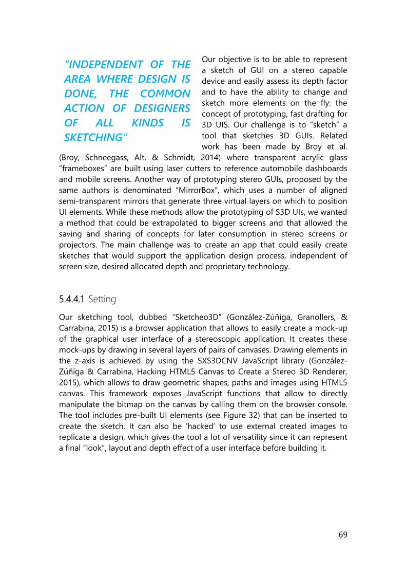
69
Our objective is to be able to represent
a sketch of GUI on a stereo capable
device and easily assess its depth factor
and to have the ability to change and
sketch more elements on the fly: the
concept of prototyping, fast drafting for
3D UIS. Our challenge is to “sketch” a
tool that sketches 3D GUIs. Related
work has been made by Broy et al.
(Broy, Schneegass, Alt, & Schmidt, 2014) where transparent acrylic glass
“frameboxes” are built using laser cutters to reference automobile dashboards
and mobile screens. Another way of prototyping stereo GUIs, proposed by the
same authors is denominated “MirrorBox”, which uses a number of aligned
semi-transparent mirrors that generate three virtual layers on which to position
UI elements. While these methods allow the prototyping of S3D UIs, we wanted
a method that could be extrapolated to bigger screens and that allowed the
saving and sharing of concepts for later consumption in stereo screens or
projectors. The main challenge was to create an app that could easily create
sketches that would support the application design process, independent of
screen size, desired allocated depth and proprietary technology.
5.4.4.1 Setting
Our sketching tool, dubbed “Sketcheo3D” (González-Zúñiga, Granollers, &
Carrabina, 2015) is a browser application that allows to easily create a mock-up
of the graphical user interface of a stereoscopic application. It creates these
mock-ups by drawing in several layers of pairs of canvases. Drawing elements in
the z-axis is achieved by using the SXS3DCNV JavaScript library (González-
Zúñiga & Carrabina, Hacking HTML5 Canvas to Create a Stereo 3D Renderer,
2015), which allows to draw geometric shapes, paths and images using HTML5
canvas. This framework exposes JavaScript functions that allow to directly
manipulate the bitmap on the canvas by calling them on the browser console.
The tool includes pre-built UI elements (see Figure 32) that can be inserted to
create the sketch. It can also be ‘hacked’ to use external created images to
replicate a design, which gives the tool a lot of versatility since it can represent
a final “look”, layout and depth effect of a user interface before building it.
“INDEPENDENT OF THE
AREA WHERE DESIGN IS
DONE, THE COMMON
ACTION OF DESIGNERS
OF ALL KINDS IS
SKETCHING”
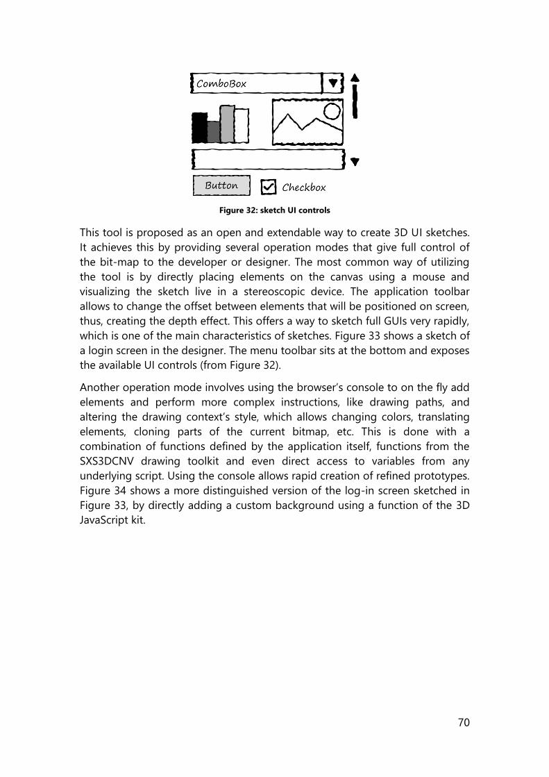
70
Figure 32: sketch UI controls
This tool is proposed as an open and extendable way to create 3D UI sketches.
It achieves this by providing several operation modes that give full control of
the bit-map to the developer or designer. The most common way of utilizing
the tool is by directly placing elements on the canvas using a mouse and
visualizing the sketch live in a stereoscopic device. The application toolbar
allows to change the offset between elements that will be positioned on screen,
thus, creating the depth effect. This offers a way to sketch full GUIs very rapidly,
which is one of the main characteristics of sketches. Figure 33 shows a sketch of
a login screen in the designer. The menu toolbar sits at the bottom and exposes
the available UI controls (from Figure 32).
Another operation mode involves using the browser’s console to on the fly add
elements and perform more complex instructions, like drawing paths, and
altering the drawing context’s style, which allows changing colors, translating
elements, cloning parts of the current bitmap, etc. This is done with a
combination of functions defined by the application itself, functions from the
SXS3DCNV drawing toolkit and even direct access to variables from any
underlying script. Using the console allows rapid creation of refined prototypes.
Figure 34 shows a more distinguished version of the log-in screen sketched in
Figure 33, by directly adding a custom background using a function of the 3D
JavaScript kit.
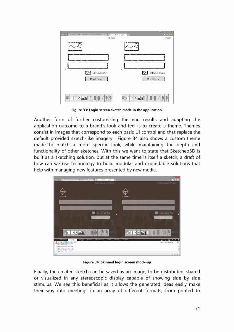
71
Figure 33: Login screen sketch made in the application.
Another form of further customizing the end results and adapting the
application outcome to a brand’s look and feel is to create a theme. Themes
consist in images that correspond to each basic UI control and that replace the
default provided sketch-like imagery. Figure 34 also shows a custom theme
made to match a more specific look, while maintaining the depth and
functionality of other sketches. With this we want to state that Sketcheo3D is
built as a sketching solution, but at the same time is itself a sketch, a draft of
how can we use technology to build modular and expandable solutions that
help with managing new features presented by new media.
Figure 34: Skinned login screen mock-up
Finally, the created sketch can be saved as an image, to be distributed, shared
or visualized in any stereoscopic display capable of showing side by side
stimulus. We see this beneficial as it allows the generated ideas easily make
their way into meetings in an array of different formats, from printed to
72
projected. They can be stored, disposed of, and most importantly, iterated
upon.
5.4.4.2 Results
This tool is a sketch. As such, it is rapidly evolving and helping us not only test
the layout of different 3D graphical user interfaces, but is also built in a way
that allows it to adapt to different scenarios, from basic sketching to being able
to feature custom in-house design. It is built using only open technologies, and
based in the latest standards while adapting the stereoscopic principles to
create innovative software UIs. The core technologies are HTML, Canvas and
JavaScript. We have sketched a tool that allows the creation of sketches of
graphical user interfaces. It uses current web technologies to draft layouts that
use depth. The benefits and differentiator of this tool is based primarily on the
fact that it can show actual stereoscopic images, with the positions defined by
parameters defined by developers or designers. The tool is flexible and can
adapt to different window (screen) sizes, and is able to run on different
platforms (Windows, Mac) and different devices like tablets and phones.
5.4.5 Stereoscopic 3D Garment Desirability Test
When we presented a clustering exercise to group the Product Reaction Cards,
we also did a small experiment to apply the newly defined groups and evaluate
the results. This preliminary test shows the use of our MRC groups, and serves
as a base to further iterate on another experiment.
5.4.5.1 Stimulus
The stimuli created are based on the analysis of existing leading online retailing
catalogs. The resulting application consists of a menu for selecting the desired
garment and a correspondent product detail page for each product. Figure 35
shows an example product detail page in 2D.
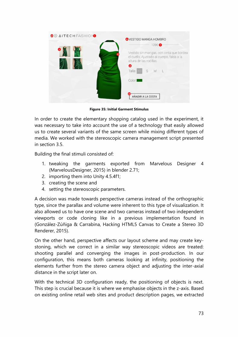
73
Figure 35: Initial Garment Stimulus
In order to create the elementary shopping catalog used in the experiment, it
was necessary to take into account the use of a technology that easily allowed
us to create several variants of the same screen while mixing different types of
media. We worked with the stereoscopic camera management script presented
in section 3.5.
Building the final stimuli consisted of:
1. tweaking the garments exported from Marvelous Designer 4
(MarvelousDesigner, 2015) in blender 2.71;
2. importing them into Unity 4.5.4f1;
3. creating the scene and
4. setting the stereoscopic parameters.
A decision was made towards perspective cameras instead of the orthographic
type, since the parallax and volume were inherent to this type of visualization. It
also allowed us to have one scene and two cameras instead of two independent
viewports or code cloning like in a previous implementation found in
(González-Zúñiga & Carrabina, Hacking HTML5 Canvas to Create a Stereo 3D
Renderer, 2015).
On the other hand, perspective affects our layout scheme and may create key-
stoning, which we correct in a similar way stereoscopic videos are treated:
shooting parallel and converging the images in post-production. In our
configuration, this means both cameras looking at infinity, positioning the
elements further from the stereo camera object and adjusting the inter-axial
distance in the script later on.
With the technical 3D configuration ready, the positioning of objects is next.
This step is crucial because it is where we emphasise objects in the z-axis. Based
on existing online retail web sites and product description pages, we extracted
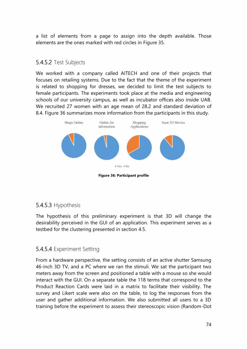
74
a list of elements from a page to assign into the depth available. Those
elements are the ones marked with red circles in Figure 35.
5.4.5.2 Test Subjects
We worked with a company called AITECH and one of their projects that
focuses on retailing systems. Due to the fact that the theme of the experiment
is related to shopping for dresses, we decided to limit the test subjects to
female participants. The experiments took place at the media and engineering
schools of our university campus, as well as incubator offices also inside UAB.
We recruited 27 women with an age mean of 28.2 and standard deviation of
8.4. Figure 36 summarizes more information from the participants in this study.
Figure 36: Participant profile
5.4.5.3 Hypothesis
The hypothesis of this preliminary experiment is that 3D will change the
desirability perceived in the GUI of an application. This experiment serves as a
testbed for the clustering presented in section 4.5.
5.4.5.4 Experiment Setting
From a hardware perspective, the setting consists of an active shutter Samsung
46-inch 3D TV, and a PC where we ran the stimuli. We sat the participant two
meters away from the screen and positioned a table with a mouse so she would
interact with the GUI. On a separate table the 118 terms that correspond to the
Product Reaction Cards were laid in a matrix to facilitate their visibility. The
survey and Likert scale were also on the table, to log the responses from the
user and gather additional information. We also submitted all users to a 3D
training before the experiment to assess their stereoscopic vision (Random-Dot
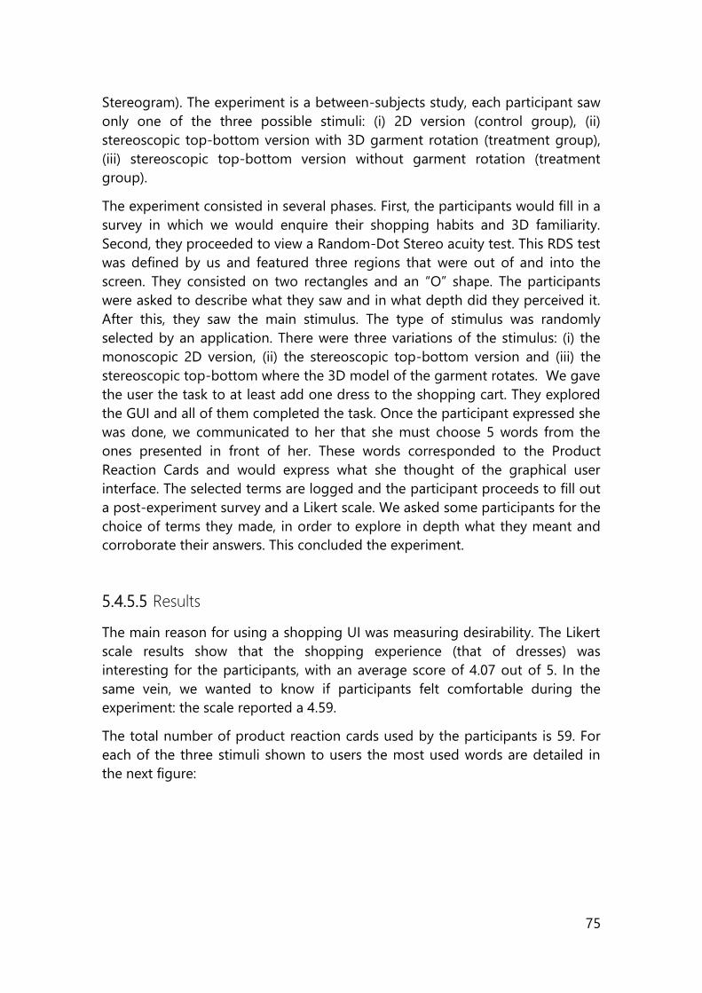
75
Stereogram). The experiment is a between-subjects study, each participant saw
only one of the three possible stimuli: (i) 2D version (control group), (ii)
stereoscopic top-bottom version with 3D garment rotation (treatment group),
(iii) stereoscopic top-bottom version without garment rotation (treatment
group).
The experiment consisted in several phases. First, the participants would fill in a
survey in which we would enquire their shopping habits and 3D familiarity.
Second, they proceeded to view a Random-Dot Stereo acuity test. This RDS test
was defined by us and featured three regions that were out of and into the
screen. They consisted on two rectangles and an “O” shape. The participants
were asked to describe what they saw and in what depth did they perceived it.
After this, they saw the main stimulus. The type of stimulus was randomly
selected by an application. There were three variations of the stimulus: (i) the
monoscopic 2D version, (ii) the stereoscopic top-bottom version and (iii) the
stereoscopic top-bottom where the 3D model of the garment rotates. We gave
the user the task to at least add one dress to the shopping cart. They explored
the GUI and all of them completed the task. Once the participant expressed she
was done, we communicated to her that she must choose 5 words from the
ones presented in front of her. These words corresponded to the Product
Reaction Cards and would express what she thought of the graphical user
interface. The selected terms are logged and the participant proceeds to fill out
a post-experiment survey and a Likert scale. We asked some participants for the
choice of terms they made, in order to explore in depth what they meant and
corroborate their answers. This concluded the experiment.
5.4.5.5 Results
The main reason for using a shopping UI was measuring desirability. The Likert
scale results show that the shopping experience (that of dresses) was
interesting for the participants, with an average score of 4.07 out of 5. In the
same vein, we wanted to know if participants felt comfortable during the
experiment: the scale reported a 4.59.
The total number of product reaction cards used by the participants is 59. For
each of the three stimuli shown to users the most used words are detailed in
the next figure:
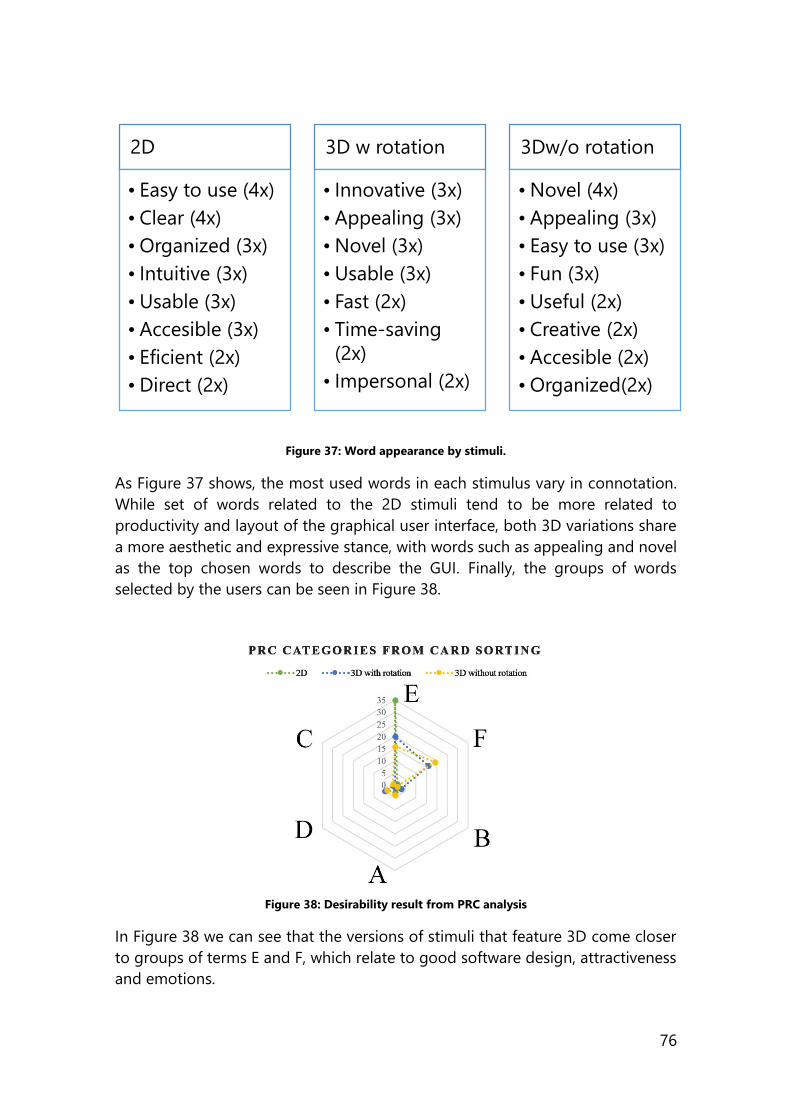
76
Figure 37: Word appearance by stimuli.
As Figure 37 shows, the most used words in each stimulus vary in connotation.
While set of words related to the 2D stimuli tend to be more related to
productivity and layout of the graphical user interface, both 3D variations share
a more aesthetic and expressive stance, with words such as appealing and novel
as the top chosen words to describe the GUI. Finally, the groups of words
selected by the users can be seen in Figure 38.
Figure 38: Desirability result from PRC analysis
In Figure 38 we can see that the versions of stimuli that feature 3D come closer
to groups of terms E and F, which relate to good software design, attractiveness
and emotions.
2D
• Easy to use (4x)
• Clear (4x)
•Organized (3x)
• Intuitive (3x)
•Usable (3x)
• Accesible (3x)
• Eficient (2x)
•Direct (2x)
3D w rotation
• Innovative (3x)
• Appealing (3x)
•Novel (3x)
•Usable (3x)
• Fast (2x)
• Time-saving
(2x)
• Impersonal (2x)
3Dw/o rotation
•Novel (4x)
• Appealing (3x)
• Easy to use (3x)
• Fun (3x)
•Useful (2x)
• Creative (2x)
• Accesible (2x)
•Organized(2x)
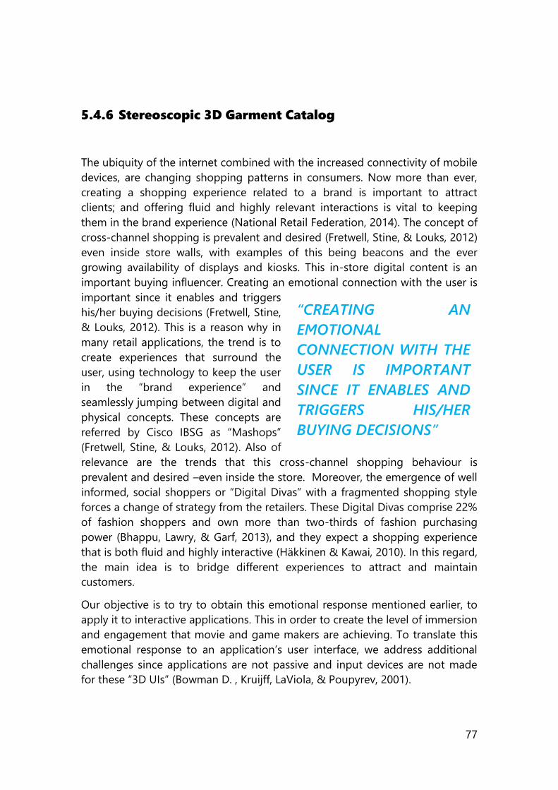
77
5.4.6 Stereoscopic 3D Garment Catalog
The ubiquity of the internet combined with the increased connectivity of mobile
devices, are changing shopping patterns in consumers. Now more than ever,
creating a shopping experience related to a brand is important to attract
clients; and offering fluid and highly relevant interactions is vital to keeping
them in the brand experience (National Retail Federation, 2014). The concept of
cross-channel shopping is prevalent and desired (Fretwell, Stine, & Louks, 2012)
even inside store walls, with examples of this being beacons and the ever
growing availability of displays and kiosks. This in-store digital content is an
important buying influencer. Creating an emotional connection with the user is
important since it enables and triggers
his/her buying decisions (Fretwell, Stine,
& Louks, 2012). This is a reason why in
many retail applications, the trend is to
create experiences that surround the
user, using technology to keep the user
in the “brand experience” and
seamlessly jumping between digital and
physical concepts. These concepts are
referred by Cisco IBSG as “Mashops”
(Fretwell, Stine, & Louks, 2012). Also of
relevance are the trends that this cross-channel shopping behaviour is
prevalent and desired –even inside the store. Moreover, the emergence of well
informed, social shoppers or “Digital Divas” with a fragmented shopping style
forces a change of strategy from the retailers. These Digital Divas comprise 22%
of fashion shoppers and own more than two-thirds of fashion purchasing
power (Bhappu, Lawry, & Garf, 2013), and they expect a shopping experience
that is both fluid and highly interactive (Häkkinen & Kawai, 2010). In this regard,
the main idea is to bridge different experiences to attract and maintain
customers.
Our objective is to try to obtain this emotional response mentioned earlier, to
apply it to interactive applications. This in order to create the level of immersion
and engagement that movie and game makers are achieving. To translate this
emotional response to an application’s user interface, we address additional
challenges since applications are not passive and input devices are not made
for these “3D UIs” (Bowman D. , Kruijff, LaViola, & Poupyrev, 2001).
“CREATING AN
EMOTIONAL
CONNECTION WITH THE
USER IS IMPORTANT
SINCE IT ENABLES AND
TRIGGERS HIS/HER
BUYING DECISIONS”
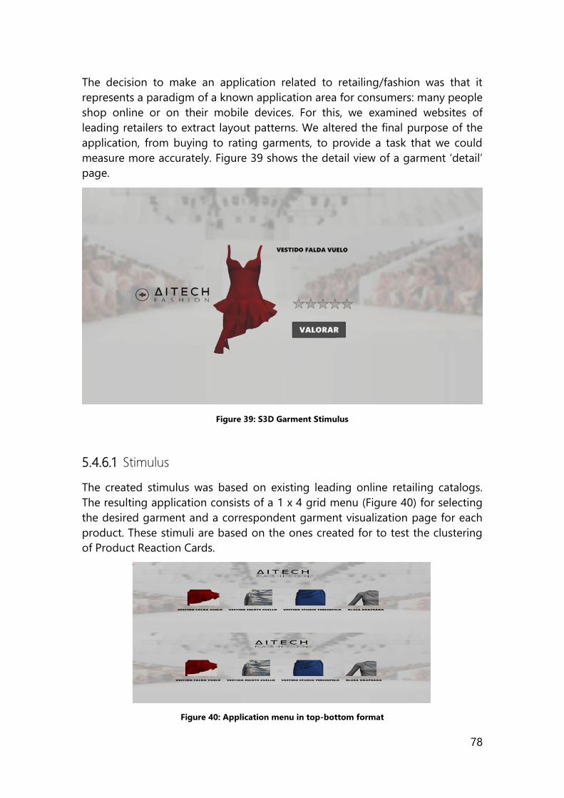
78
The decision to make an application related to retailing/fashion was that it
represents a paradigm of a known application area for consumers: many people
shop online or on their mobile devices. For this, we examined websites of
leading retailers to extract layout patterns. We altered the final purpose of the
application, from buying to rating garments, to provide a task that we could
measure more accurately. Figure 39 shows the detail view of a garment ‘detail’
page.
Figure 39: S3D Garment Stimulus
5.4.6.1 Stimulus
The created stimulus was based on existing leading online retailing catalogs.
The resulting application consists of a 1 x 4 grid menu (Figure 40) for selecting
the desired garment and a correspondent garment visualization page for each
product. These stimuli are based on the ones created for to test the clustering
of Product Reaction Cards.
Figure 40: Application menu in top-bottom format
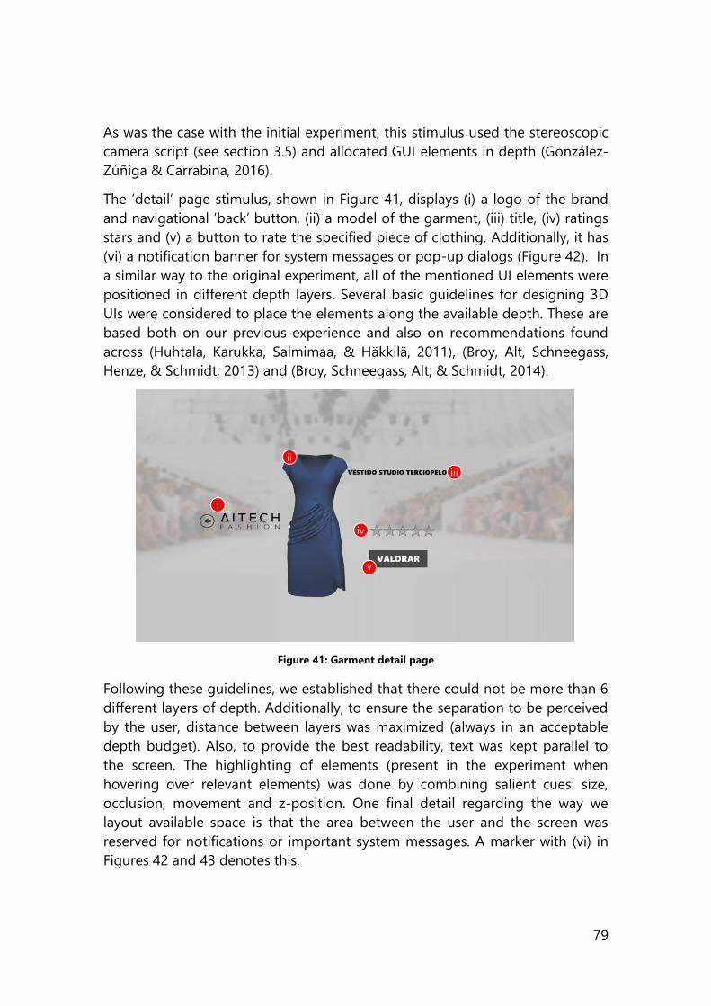
79
As was the case with the initial experiment, this stimulus used the stereoscopic
camera script (see section 3.5) and allocated GUI elements in depth (González-
Zúñiga & Carrabina, 2016).
The ‘detail’ page stimulus, shown in Figure 41, displays (i) a logo of the brand
and navigational ‘back’ button, (ii) a model of the garment, (iii) title, (iv) ratings
stars and (v) a button to rate the specified piece of clothing. Additionally, it has
(vi) a notification banner for system messages or pop-up dialogs (Figure 42). In
a similar way to the original experiment, all of the mentioned UI elements were
positioned in different depth layers. Several basic guidelines for designing 3D
UIs were considered to place the elements along the available depth. These are
based both on our previous experience and also on recommendations found
across (Huhtala, Karukka, Salmimaa, & Häkkilä, 2011), (Broy, Alt, Schneegass,
Henze, & Schmidt, 2013) and (Broy, Schneegass, Alt, & Schmidt, 2014).
Figure 41: Garment detail page
Following these guidelines, we established that there could not be more than 6
different layers of depth. Additionally, to ensure the separation to be perceived
by the user, distance between layers was maximized (always in an acceptable
depth budget). Also, to provide the best readability, text was kept parallel to
the screen. The highlighting of elements (present in the experiment when
hovering over relevant elements) was done by combining salient cues: size,
occlusion, movement and z-position. One final detail regarding the way we
layout available space is that the area between the user and the screen was
reserved for notifications or important system messages. A marker with (vi) in
Figures 42 and 43 denotes this.
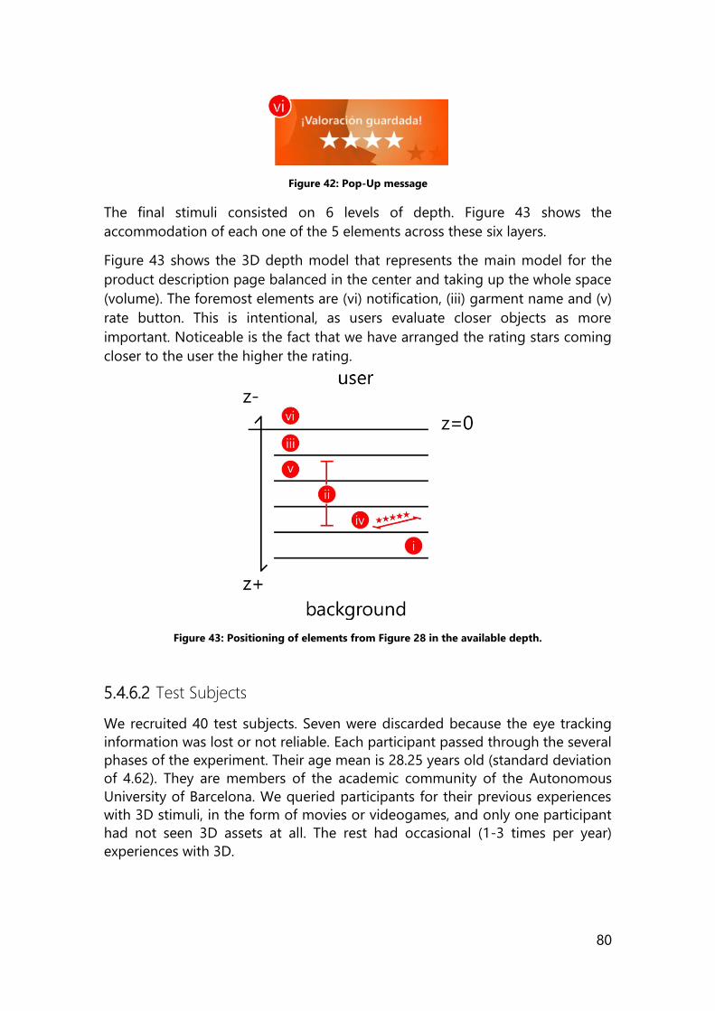
80
Figure 42: Pop-Up message
The final stimuli consisted on 6 levels of depth. Figure 43 shows the
accommodation of each one of the 5 elements across these six layers.
Figure 43 shows the 3D depth model that represents the main model for the
product description page balanced in the center and taking up the whole space
(volume). The foremost elements are (vi) notification, (iii) garment name and (v)
rate button. This is intentional, as users evaluate closer objects as more
important. Noticeable is the fact that we have arranged the rating stars coming
closer to the user the higher the rating.
Figure 43: Positioning of elements from Figure 28 in the available depth.
5.4.6.2 Test Subjects
We recruited 40 test subjects. Seven were discarded because the eye tracking
information was lost or not reliable. Each participant passed through the several
phases of the experiment. Their age mean is 28.25 years old (standard deviation
of 4.62). They are members of the academic community of the Autonomous
University of Barcelona. We queried participants for their previous experiences
with 3D stimuli, in the form of movies or videogames, and only one participant
had not seen 3D assets at all. The rest had occasional (1-3 times per year)
experiences with 3D.
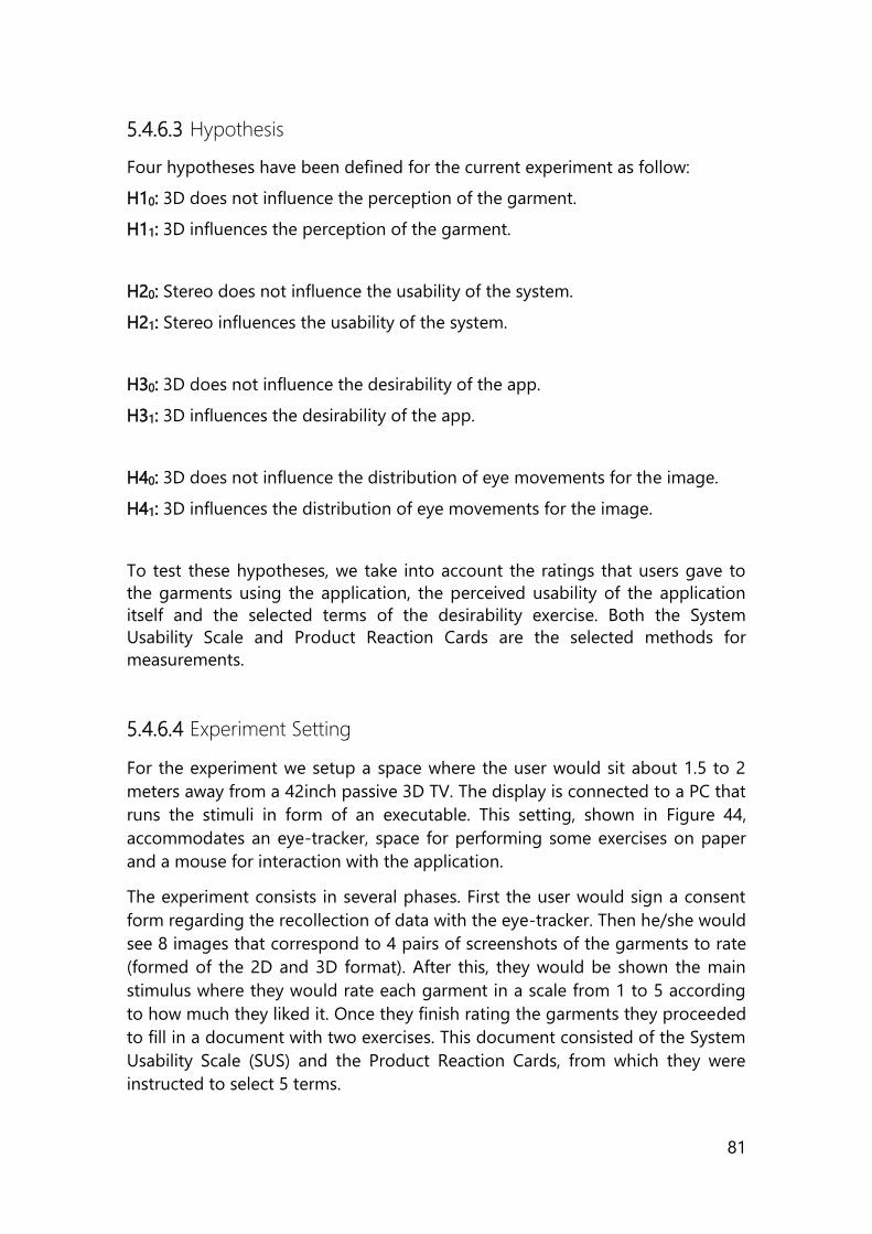
81
5.4.6.3 Hypothesis
Four hypotheses have been defined for the current experiment as follow:
H10: 3D does not influence the perception of the garment.
H11: 3D influences the perception of the garment.
H20: Stereo does not influence the usability of the system.
H21: Stereo influences the usability of the system.
H30: 3D does not influence the desirability of the app.
H31: 3D influences the desirability of the app.
H40: 3D does not influence the distribution of eye movements for the image.
H41: 3D influences the distribution of eye movements for the image.
To test these hypotheses, we take into account the ratings that users gave to
the garments using the application, the perceived usability of the application
itself and the selected terms of the desirability exercise. Both the System
Usability Scale and Product Reaction Cards are the selected methods for
measurements.
5.4.6.4 Experiment Setting
For the experiment we setup a space where the user would sit about 1.5 to 2
meters away from a 42inch passive 3D TV. The display is connected to a PC that
runs the stimuli in form of an executable. This setting, shown in Figure 44,
accommodates an eye-tracker, space for performing some exercises on paper
and a mouse for interaction with the application.
The experiment consists in several phases. First the user would sign a consent
form regarding the recollection of data with the eye-tracker. Then he/she would
see 8 images that correspond to 4 pairs of screenshots of the garments to rate
(formed of the 2D and 3D format). After this, they would be shown the main
stimulus where they would rate each garment in a scale from 1 to 5 according
to how much they liked it. Once they finish rating the garments they proceeded
to fill in a document with two exercises. This document consisted of the System
Usability Scale (SUS) and the Product Reaction Cards, from which they were
instructed to select 5 terms.
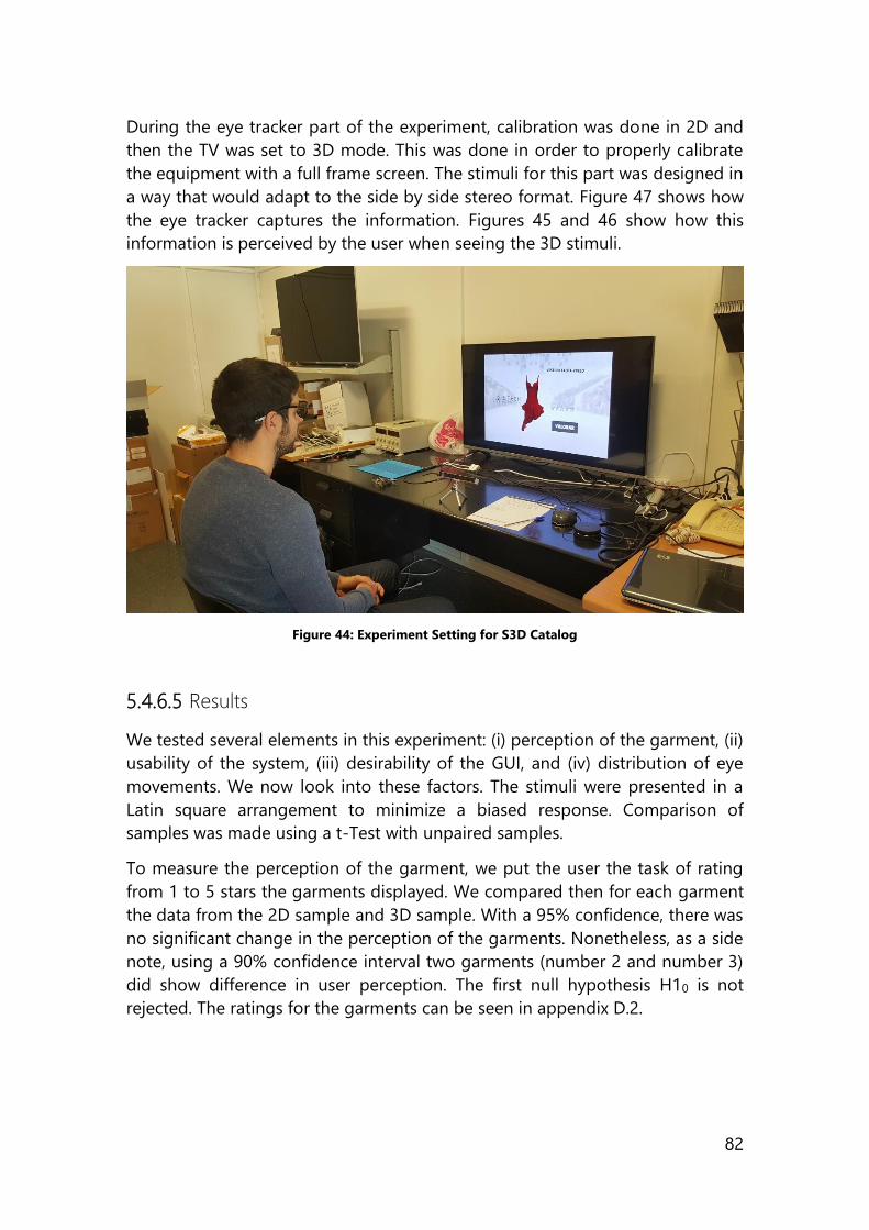
82
During the eye tracker part of the experiment, calibration was done in 2D and
then the TV was set to 3D mode. This was done in order to properly calibrate
the equipment with a full frame screen. The stimuli for this part was designed in
a way that would adapt to the side by side stereo format. Figure 47 shows how
the eye tracker captures the information. Figures 45 and 46 show how this
information is perceived by the user when seeing the 3D stimuli.
Figure 44: Experiment Setting for S3D Catalog
5.4.6.5 Results
We tested several elements in this experiment: (i) perception of the garment, (ii)
usability of the system, (iii) desirability of the GUI, and (iv) distribution of eye
movements. We now look into these factors. The stimuli were presented in a
Latin square arrangement to minimize a biased response. Comparison of
samples was made using a t-Test with unpaired samples.
To measure the perception of the garment, we put the user the task of rating
from 1 to 5 stars the garments displayed. We compared then for each garment
the data from the 2D sample and 3D sample. With a 95% confidence, there was
no significant change in the perception of the garments. Nonetheless, as a side
note, using a 90% confidence interval two garments (number 2 and number 3)
did show difference in user perception. The first null hypothesis H10 is not
rejected. The ratings for the garments can be seen in appendix D.2.
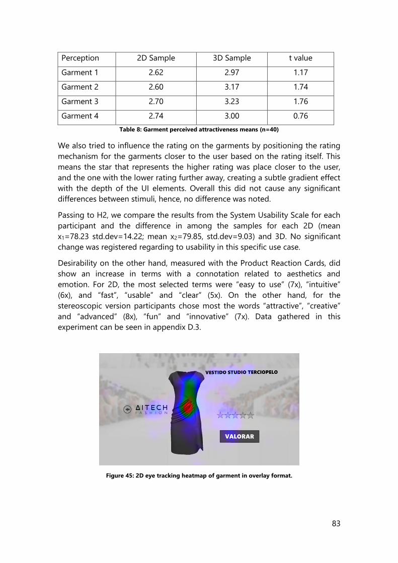
83
Perception 2D Sample 3D Sample t value
Garment 1 2.62 2.97 1.17
Garment 2 2.60 3.17 1.74
Garment 3 2.70 3.23 1.76
Garment 4 2.74 3.00 0.76
Table 8: Garment perceived attractiveness means (n=40)
We also tried to influence the rating on the garments by positioning the rating
mechanism for the garments closer to the user based on the rating itself. This
means the star that represents the higher rating was place closer to the user,
and the one with the lower rating further away, creating a subtle gradient effect
with the depth of the UI elements. Overall this did not cause any significant
differences between stimuli, hence, no difference was noted.
Passing to H2, we compare the results from the System Usability Scale for each
participant and the difference in among the samples for each 2D (mean
x1=78.23 std.dev=14.22; mean x2=79.85, std.dev=9.03) and 3D. No significant
change was registered regarding to usability in this specific use case.
Desirability on the other hand, measured with the Product Reaction Cards, did
show an increase in terms with a connotation related to aesthetics and
emotion. For 2D, the most selected terms were “easy to use” (7x), “intuitive”
(6x), and “fast”, “usable” and “clear” (5x). On the other hand, for the
stereoscopic version participants chose most the words “attractive”, “creative”
and “advanced” (8x), “fun” and “innovative” (7x). Data gathered in this
experiment can be seen in appendix D.3.
Figure 45: 2D eye tracking heatmap of garment in overlay format.
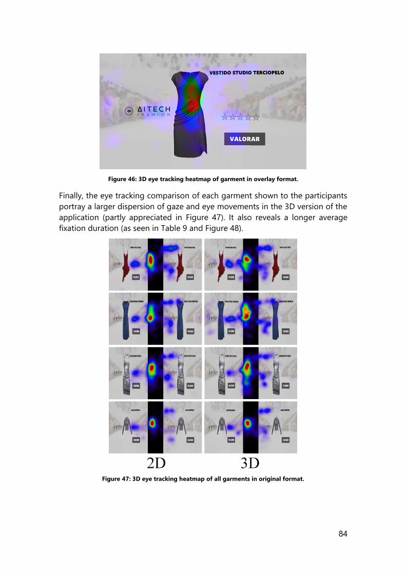
84
Figure 46: 3D eye tracking heatmap of garment in overlay format.
Finally, the eye tracking comparison of each garment shown to the participants
portray a larger dispersion of gaze and eye movements in the 3D version of the
application (partly appreciated in Figure 47). It also reveals a longer average
fixation duration (as seen in Table 9 and Figure 48).
Figure 47: 3D eye tracking heatmap of all garments in original format.
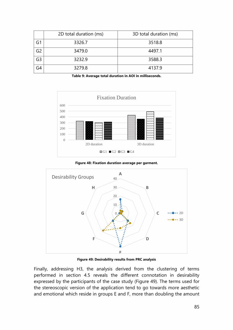
85
2D total duration (ms) 3D total duration (ms)
G1 3326.7 3518.8
G2 3479.0 4497.1
G3 3232.9 3588.3
G4 3279.8 4137.9
Table 9: Average total duration in AOI in milliseconds.
Figure 48: Fixation duration average per garment.
Figure 49: Desirability results from PRC analysis
Finally, addressing H3, the analysis derived from the clustering of terms
performed in section 4.5 reveals the different connotation in desirability
expressed by the participants of the case study (Figure 49). The terms used for
the stereoscopic version of the application tend to go towards more aesthetic
and emotional which reside in groups E and F, more than doubling the amount
0
100
200
300
400
500
600
2D duration 3D duration
Fixation Duration
G1 G2 G3 G4
0
10
20
30
40A
B
C
D
E
F
G
H
Desirability Groups
2D
3D
86
of terms in comparison to the monoscopic version. Meanwhile terms on the 2D
version of the same stimulus focuses more on good software design and
productivity found in groups D and E.
5.5 Summary of the chapter
This chapter assembles the concepts presented in previous chapters and shows
a graphical representation of a stereoscopic application pipeline. This pipeline
(theory, prototyping, development and evaluation) is the central part of the
present work, were we present contributions and measure changes achieved in
our 3D generated scenarios.
An important part of our work as well, is the exploration of the changes in
human factors triggered by depth. It is agreed that this is completely
dependent on the task, and that many authors and developers use it in
different ways. According to the tasks at hand, we decided to use depth as a
cue for selected/highlighted elements. Also, to indicate importance or rating,
and to separate toolbars and menus from the working area.
Discrete and analog applications are presenting, making clear how can we
create different types of applications. This is important to take into account
while choosing among the tools available.
The present chapter also takes technical concepts presented in chapter 3 and
human factor concepts from chapter 4 to present 6 case studies where the
changes of a graphical user interface due to the introduction of depth are
measured. These cases are composed of 2 preliminary tests (eye tracking and
desirability) and 4 experiments that introduce depth in different ways. A
stereoscopic search engine result page that rates results using depth, a stereo
3D memory game that highlights selected cards using depth, a sketching
application that uses depth to position elements in space and separate the
menu bars, and a stereoscopic 3D garment catalog that combines 3D models
and GUI elements in space to poll usability and desirability. We now examine
the results of these case studies, and lay the conclusions to the present work.
87
Section Three
Making sense of depth in
software Stereoscopic depth has not been fully exploited in software, yet its benefits can
be seen across its use to enhance tasks and guide the user. The lack of a
pipeline to create this type of stimuli is an issue that needs to be tackled in
order for this type of software to expand, and the reason for this type of
software to expand and exist is that it can provide better user experience than
2D versions. All examples and uses of depth vary and are related to the task in
hand. We have developed and documented cases where introducing depth
enhances the UX.
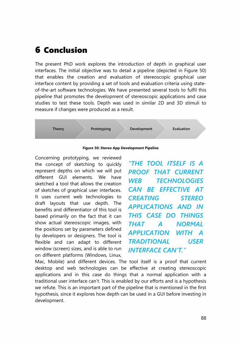
88
6 Conclusion
The present PhD work explores the introduction of depth in graphical user
interfaces. The initial objective was to detail a pipeline (depicted in Figure 50)
that enables the creation and evaluation of stereoscopic graphical user
interface content by providing a set of tools and evaluation criteria using state-
of-the-art software technologies. We have presented several tools to fulfil this
pipeline that promotes the development of stereoscopic applications and case
studies to test these tools. Depth was used in similar 2D and 3D stimuli to
measure if changes were produced as a result.
Figure 50: Stereo App Development Pipeline
Concerning prototyping, we reviewed
the concept of sketching to quickly
represent depths on which we will put
different GUI elements. We have
sketched a tool that allows the creation
of sketches of graphical user interfaces.
It uses current web technologies to
draft layouts that use depth. The
benefits and differentiator of this tool is
based primarily on the fact that it can
show actual stereoscopic images, with
the positions set by parameters defined
by developers or designers. The tool is
flexible and can adapt to different
window (screen) sizes, and is able to run
on different platforms (Windows, Linux,
Mac, Mobile) and different devices. The tool itself is a proof that current
desktop and web technologies can be effective at creating stereoscopic
applications and in this case do things that a normal application with a
traditional user interface can’t. This is enabled by our efforts and is a hypothesis
we refute. This is an important part of the pipeline that is mentioned in the first
hypothesis, since it explores how depth can be used in a GUI before investing in
development.
Theory Prototyping Development Evaluation
“THE TOOL ITSELF IS A
PROOF THAT CURRENT
WEB TECHNOLOGIES
CAN BE EFFECTIVE AT
CREATING STEREO
APPLICATIONS AND IN
THIS CASE DO THINGS
THAT A NORMAL
APPLICATION WITH A
TRADITIONAL USER
INTERFACE CAN’T.”
89
Regarding tool development, among the technologies we tested, HTML5
Canvas was the most performant, flexible and functional due to its inherent
JavaScript background, compatibility (Deveria, 2014), and the uniformity of its
implementation. The fact that canvas is a feature built into the web specification
guarantees execution of the code in a wide range of platforms. Nonetheless, of
the two contexts of the canvas (‘2d’ and ‘webgl’), none is stereoscopic out of
the box and the ‘webgl’ has partial support due to some video drivers and an
experimental context on browsers like Microsoft Edge. We developed a solution
that wraps the standard ‘2d’ context providing a side by side solution proved to
work in a broad set of devices. The implementation duplicates drawing
commands and manages to draw up to 20000 shapes per frame (and more on
hardware accelerated browser). Table 3 showed us an average of 392%
difference in size ratio between common image file formats and our canvas
representation for a stereoscopic representation of a chart. In this way, we can
store vector-like images in smaller sizes than with raster formats.
On the desktop platform, the Unity game engine allows the creation of dual
viewports assigned to different camera, creating the stereo effect. The engine
does not provide a stereoscopic configuration out of the box (except for third
party plug-ins). Similarly to our approach for the 2D context, we coded a stereo
camera management script that takes two cameras and builds a rig wrapper
that handles the 3D parameters. Overall, the efforts in development represent a
base on to which new experiences can be created and targets a gap where no
easily accessible methods exist that enhance both utility and aesthetics, always
noting the differences in user behavior when introducing depth.
Concerning evaluation, and to prove our hypothesis, we developed 6 case
studies to test different repercussions of depth. First, a Preliminary Eye Tracking
test and a Stereoscopic Search Engine Result Page. From them, we inferred that
there is a change in viewing patterns, both dwell time and viewing sequence
order, and this must be taken into account when positioning elements in the
GUI. We also noticed that both dwell time and fixation duration are greater
when experiencing 3D stimuli. Following, a Stereo 3D Memory Game, where we
learnt that greater dwell times do not necessarily mean lower performance. In
this case, we measured effectiveness and efficiency to show that participants
were able to complete the tasks faster when using depth to separate elements
with an average difference of 5.19 seconds (faster in the 3D stimulus). This
separation in different groups was achieved by using different z-axis positions.
On the other hand, if time is not a defining element in the task at hand, 3D still
changes the gaze order in an application and can be used to direct the user
towards content in different depth.
Finally, we explored two test cases based on a Stereoscopic Garment Catalog. In
this example, changes are visible in the perceived desirability of the software.
90
Remembering that desirability is related to the way something looks and feels,
it encompasses constructs that are not easily measured by usability tests.
Product Reaction Cards can get a reliable portrait of a system’s desirability, but
the management and analysis of word appearance among 118 terms can be
cumbersome and costly timewise. Therefore, we have grouped PRCs to
measure desirability in an application using a traditional clustering exercise.
We can now get a snapshot of a user interface’s desirability by counting words
that have similar connotation. We can apply this classification to the results
collected from participants in order to analyse the inclusion of stereoscopic
depth in a graphical user interface. The created classification is an initial effort
to provide UI and UX practitioners with an additional layer of information
extracted from PRCs.
When plotting the results in a radar chart, we can see in a preliminary test and
case study that the stereoscopic versions of the application tend to go towards
more aesthetic and emotional terms (found in groups E and F, terms like
“attractive”, “creative”, “advanced”, “fun” and “innovative”). These terms more
than double the number of terms in comparison to the 2D version in those
groups. Meanwhile terms selected for the 2D versions of the same apps
focused more on good software design and productivity (found in groups D
and E, specifically “easy to use”, “intuitive”, “fast”, “clear” and “usable”). Worth
noticing also is the fact that participants tended to select a wider set of terms
for the 2D version of the stimulus. The similarity in meaning and connotations
of a set of words, even among a controlled focus group of final users of any
software can be large. Therefore, having
a tool that allows us to aggregate these
potentially similar meanings is of great
value towards enhancing the core
experience of a product.
Nonetheless, this is not the same
experience with our tests on perception
of products/items in the application
itself. One of the studies involved rating
garments which were shown to the
users as 3D models. Similarly to
previous studies, both monoscopic and
stereoscopic versions were shown, but
there was no solid evidence of higher
resulting ratings between the samples taken from the two stimuli. Another
aspect that did not influence the ratings of garments was the position of the
rating mechanism, which consisted of 5 stars that came closer to the user in
“HAVING A TOOL THAT
ALLOWS US TO
AGGREGATE THESE
POTENTIALLY SIMILAR
MEANINGS IS OF GREAT
VALUE TOWARDS
ENHANCING THE CORE
EXPERIENCE OF A
PRODUCT.”
91
accordance to the represented rating. This served as a repetition cue, along
with color.
Finally, we demonstrate that there is an opportunity to use stereo 3D images
not only for image and videogames but also for interactive applications.
Hardware, software and consumer trends have not made possible a big
explosion of the technology, so our research can be considered a pioneering
one. As such, the design, implementation and testing of our hypothesis show
novel results, not comparable with any other previous implementations. With
this said, in a close future new 3D UI interfaces will appear for this kind of
applications that will create more radical and innovative user experiences than
those expected by classical navigation and mouse actions present in our
prototype.
As a summary, we believe this research is contributing to enhance the
theoretical basis concerning development of stereoscopic graphical user
interfaces. For each part of the explored pipeline, we have presented tools and
knowledge that directly impact the process and insight we have for 3D on
applications. By using eye-tracking technology we have shown that gaze
changes, both in order and dwell time. This is fundamental, since the way we
experience 3D in passive stimuli like movies change, and adding interactivity
influences other human factors. We have explored these human factors, in
cases that range from usability to desirability, producing at the same time tools
that enable an easy creation and evaluation of assets to measure these UX
constructs.
6.1 Future Work
The environment around stereoscopic assets has evolved greatly in the past
years. Nowadays, the revolution in multimedia experiences, which is being
powered by VR, brings a lot of relevance to the presented work. This relevance
is not because of the virtual environments that have existed (but are being
adapted into VR) long before in videogames but because of the migration of
more traditional and familiar tasks into VR. Future lines of research that can
build upon the present work span across different subjects like: (i) Virtual
Reality and Augmented Reality, (ii) different task examples of other traditional
apps, (iii) comparison of different depth layouts for tasks, (iv) interaction with
gestures in 3D apps, (v) innovative use of depth for interfaces and (vi) areas
where depth will enhance a task.
Virtual Reality and Augmented Reality: an obvious line of future work
since VR itself needs stereoscopic images. But getting away from virtual
environments, videos, games and experiences, lies the question of how
can 2D elements take advantage of the immersion in more traditional
92
applications. More and more examples of experiments that replicate
desktops or browsers are coming out, yet have undermined concepts
based on 2D interaction. A good way to start would be to have a way to
convert a 2D application that features content to VR.
Different task examples of other traditional apps: we studied the case of a
search engine, a pairs game and a garment catalog. But many other
types of applications should be explored with depth. The exploration of
depth in different tasks can lead to defining patterns and common
practices in software, like the ones that already exist for 2D apps.
Productivity applications, data visualization and dashboards are good
examples.
Comparison of different layouts for tasks: manipulating the depth budget
in an application can lead to very different results. We can use depth to
change where the user is looking, and we can guide a user by the
amount of depth that we utilize in a GUI. Measuring the impact of depth
and different layouts of 3D for tasks can yield different results that could
change the user experience.
Interactions with gestures in 3D apps: Stereoscopic applications have the
advantage of using depth to modify a task. But this introduction of
depth brings its own challenges regarding selection, navigation and
manipulation of content, and modification of underlying technology
(both hardware and software) to interact in space. Mapping and defining
these gestures to commands in the application provides a challenge
since the threshold for depth, stability and physical positioning requires
adaptation to available space and task in hand.
Innovative use of depth for interfaces: a novel and creative line of
research and future work is related to how do you use the available
depth in a better way. Overlaying content, playing with transparencies,
and making a better use of the space, thinking outside the 2D layout box
can improve the use of depth. This can mean breaking away from
familiarity of layouts, interactions and paradigms to test ideas. As an
example, creating a layered graphical interface that can semantically
separate information on layers and use transparency to augment the
layers beneath can be very useful as a mean to interchange the working
context of information.
Areas where depth will enhance a task: While it might be possible that
some tasks will be enhanced by the introduction of depth, others won’t.
It is important to determine which areas and tasks are suitable to be
used with depth. This can identify subjects in which it makes sense to use
depth, like math, science and multimedia. Whether a word processor or
spreadsheet require stereoscopic 3D in their GUIs is something that is
yet to be seen.
93
Finally, depth can have positive effects on a user interface and new mediums are
adopting stereo as an essential part of their platforms. To research where is it
suitable to utilise 3D, as well as how to utilize it will change our way of
interacting. It might start as elements that seemed to go into a TV screen, but
the market is already dictating the virtual environments that will house near
future interactions, all which base experiences on blank canvases ready to have
elements positioned in front of behind them. Augmented reality is following
similar steps, where menus and information interact with the environment.
These experiences have one common denominator: Stereoscopic 3D user
interfaces.
94
References
Acuña, A. (2015). Implementación de biblioteca para graficación estereoscópica.
TFG EN INGENIERÍA ELECTRÓNICA DE TELECOMUNICACIONES, ESCUELA
DE INGENIERÍA, UNIVERSIDAD AUTÓNOMA DE BARCELONA.
American Cinematographer. (1953). Is 3-D dead…? pp. 586-609.
Autodesk. (2015, May 18). Autodesk. Retrieved from Autodesk:
www.autodesk.com
AWWWARDS. (2015, March 17). 10 Stereoscopic 3D websites. Retrieved from
AWWWARDS: http://www.awwwards.com/10-stereoscopic-3d-
websites.html
Bach, C., & Scapin, D. (2003). Ergonomic criteria adapted to human virtual
environment interaction. Proceedings of the 15th French-speaking
conference on human-computer interaction on 15eme Conference
Francophone sur l'Interaction Homme-Machine - IHM 2003 (pp. 24-31).
ACM Press.
Baekdal, T. (2006, June 19). The Battle Between Usability and User-Experience.
Retrieved from baekdal.com: http://www.baekdal.com/insights/usabilty-
vs-user-experience-battle
Bailly, G., Walter, R., Müller, J., Ning, T., & Lecolinet, E. (2011). Comparing Free
Hand Menu Techniques for Distant. Human-Computer Interaction –
INTERACT 2011 Lecture Notes in Computer Science Volume 6947, (pp.
248-262).
Bangor, A., Kortum, P., & Miller, J. (2008). An Empirical Evaluation of the System
Usability Scale. International Journal of Human-Computer Interaction,
574-594.
Barnum, C. M., & Palmer, L. A. (2010). More than a feeling. Proceedings of the
28th of the international conference extended abstracts on Human
factors in computing systems - CHI EA '10 (p. 4703). New York: ACM
Press.
Bay, M. (Director). (2011). Transformers: Dark of the Moon [Motion Picture].
Benedek, J., & Miner, T. (2002). Measuring Desirability: New methods for
evaluating desirability in a usability lab setting. Proceedings of Usability
Professionals Association, (pp. 8-12).
Benedek, J., & Miner, T. (2002). Product Reaction Cards. Retrieved from
microsoft.com:
95
http://www.microsoft.com/usability/UEPostings/ProductReactionCards.d
oc
Bhappu, A., Lawry, C., & Garf, R. (2013). Digital Diva. Executive Report. University
of Arizona.
Black, S. (Director). (2013). Iron Man 3 [Motion Picture].
blender. (2015, May 18). blender. Retrieved from blender: wwww.blender.org
Block, B., & McNally, P. (2013). 3D Storytelling. Focal Press.
Bowman, D., Kruijff, E., LaViola, J. J., & Poupyrev, I. (2001). An Introduction to 3-
D User Interface Design. Presence: Teleoperators and Virtual
Environments, 96-108.
Bowman, D., Kruijff, E., LaViola, J., & Poupyrev, I. (2004). 3D User Interfaces:
Theory and Practice. Addison-Wesley Professional.
Bredow, R. E. (2006, May 25). Making It Real: The Future of Stereoscopic 3D Film
Technology. (E. A. Umble, Interviewer)
Brooke, J. (2013) SUS: A Retrospective. Journal of Usability Studies (pp 29-40).
UXPA.
Brooke, J. (1996). SUS: a 'quick and dirty' usability scale. In P. Jordan, B. Thomas,
B. Weerdmeester, & I. McClelland, Usability Evaluation in Industry (pp.
189-194). Taylor & Francis.
Brooks, F. (1999). What's real about virtual reality? IEEE Computer Graphics and
Applications, 16-27.
Broy, N., Alt, F., Schneegass, S., Henze, N., & Schmidt, A. (2013). Perceiving
layered information on 3D displays using binocular disparity.
Proceedings of the 2nd ACM International Symposium on Pervasive
Displays - PerDis '13 (p. 61). New York: ACM Press.
Broy, N., André, E., & Schmidt, A. (2012). Is stereoscopic 3D a better choice for
information representation in the car? Proceedings of the 4th
International Conference on Automotive User Interfaces and Interactive
Vehicular Applications - AutomotiveUI '12 (p. 93). New York: ACM Press.
Broy, N., Schneegass, S., Alt, F., & Schmidt, A. (2014). FrameBox and MirrorBox.
Proceedings of the 32nd annual ACM conference on Human factors in
computing systems - CHI '14 (pp. 2037-2046). New York: ACM Press.
Bruder, G., Lubas, P., & Steinicke, F. (2015). Cognitive Resource Demands of
Redirected Walking. IEEE transactions on visualization and computer
graphics, 539-544.
96
Buck, C., & Lee, J. (Directors). (2013). Frozen [Motion Picture].
Buxton, B. (2007). Sketching User Experiences: Getting the Design Right and the
Right Design. Morgan Kaufmann.
Calvo-Fernández, A., Ortega, S., & Valls, A. (n.d.). Métodos de evaluación con
usuarios. Retrieved from UOC:
http://openaccess.uoc.edu/webapps/o2/bitstream/10609/9865/1/PID_00
176614.pdf
Cameron, J. (Director). (1997). Titanic [Motion Picture].
Cameron, J. (Director). (2009). Avatar [Motion Picture].
Carpenter, J. (2014, December 9). QUICK VR MOCKUPS WITH ILLUSTRATOR.
Retrieved from MozVR: http://mozvr.com/posts/quick-vr-prototypes/
Chabin, J. (2014). 3D Creative Summit2014.
Chen, W., Ladeveze, N., Clavel, C., Mestre, D., & Bourdot, P. (2015). User
cohabitation in multi-stereoscopic immersive virtual environment for
individual navigation tasks. 2015 IEEE Virtual Reality (VR) (pp. 47-54).
Arles: IEEE.
Chistyakov, A. (2015, December 16). 3dsjq. Retrieved from GitHub:
https://github.com/LoomyBear/3dsjq
Chistyakov, A., Gonzalez-Zuniga, D., & Carrabina, J. (2013). Bringing the Web
Closer: Stereoscopic 3D Web Conversion. Human Computer Interaction,
Lecture Notes in Computer Science Volume 8278 (pp. 22-25). Springer
International Publishing.
Craddock, S. (2014). 3D Creative Summit 2014.
Cuarón, A. (Director). (2013). Gravity [Motion Picture].
Dang, N.-T., Le, H.-H., & Tavanti, M. (2003). Visualization and interaction on
flight trajectory in a 3D stereoscopic environment. Digital Avionics
Systems Conference, 2003. DASC '03. The 22nd. Indianapolis, IN, USA:
IEEE.
Deveria, A. (2014). Can I use canvas? Retrieved from Can I Use:
http://caniuse.com/#search=canvas
diekus. (2015, May 21). SXS3DCNV. Retrieved from GitHub.com:
https://github.com/diekus/SXS3D-CNV
Dong-Young Lee, S. H. (2015, March 17). Stereoscopic 3D Web. Retrieved from
http://www.w3.org/: http://www.w3.org/2012/10/29-webtv-
slides/Stereo_3D_Web_LGE.pdf
97
Eight Media. (2015, August 10). Hammer.JS. Retrieved from Hammer.JS:
https://hammerjs.github.io/
Eisenstein, S. (1949). About stereoscopic cinema. Penguin Film Review, pp. 34-
45.
Fallman, D. (2003). Design-Oriented Human-Computer Interaction. SIGCHI
Conference on Human Factors in Computing Systems (CHI'03) (pp. 225-
232). ACM Press.
FileInfo.com. (2015, May 13). 3D Image File Types. Retrieved from FileInfo.com:
http://http://fileinfo.com/filetypes/3d_image
Freeman, J., Lessiter, J., & W. Ijsselsteijn. (2001). Immersive television. The
Psychologist, 190-194.
Fretwell, L., Stine, J., & Louks, J. (2012). Catch’Em and Keep’Em: Revitalizing the
Store in a Cross-Channel World. Technical Report. Cisco.
González-Zúñiga, D., & Carrabina, J. (2015). Hacking HTML5 Canvas to Create a
Stereo 3D Renderer. Proceedings of the IEEE 10th Symposium on 3D
User Interfaces 2015 (pp. 155-156). Arles: IEEE.
González-Zúñiga, D., & Carrabina, J. (2016). Clustering to Categorize Desirability
in Software: Exploring Cluster Analysis of Product Reaction Cards in a
Stereoscopic Retail Application. Digital Media Industry and Academic
Forum. Santorini: IEEE.
González-Zúñiga, D., Acuña-Silvera, A., Martí-Godía, E., & Carrabina, J. (2016).
Exploring the Introduction of Stereoscopic Depth in Applications to
Change Perceived Quality. 8th International Conference on Quality of
Multimedia Experience . Lisbon : IEEE.
Gonzalez-Zuniga, D., Chistyakov, A., & Carrabina, J. (2014). Re-defining a
Pattern: Stereoscopic Web Perception. Latin America Transactions, IEEE,
12(3), 514-519.
González-Zúñiga, D., Granollers, T., & Carrabina, J. (2015). Sketching
Stereoscopic GUIs with HTML5 Canvas. Ubiquitous Computing and
Ambient Intelligence. Sensing, Processing, and Using Environmental
Information (pp. 289-296). Springer.
Google. (2015, August 10). Cardboard Design Lab. Retrieved from
play.google.com:
https://play.google.com/store/apps/details?id=com.google.vr.cardboard.
apps.designlab
98
Google. (2015, March 17). Google Cardboard. Retrieved from Google
Cardboard: http://www.google.com/get/cardboard/
Google. (2015, 04 14). Google Cardboard. Retrieved from Google Cardboard:
https://www.google.com/get/cardboard/
Google. (2015, August 18). What is material? > Elevation and shadows.
Retrieved from Google : https://www.google.com/design/spec/what-is-
material/elevation-shadows.html#elevation-shadows-elevation-android-
Gould, J. D., & Lewis, C. (1985). Designing for usability: key principles and what
designers think. Communications of the ACM, 300-311.
Granka, L., Joachims, T., & Gay, G. (2004). Eye-tracking analysis of user behavior
in WWW search. Proceedings of the 27th annual international
conference on Research and development in information retrieval - SIGIR
'04, 478.
Gross, B. C., Erkal, J. L., Lockwood, S. Y., Chen, C., & Spence, D. M. (2014).
Evaluation of 3D printing and its potential impact on biotechnology and
the chemical sciences. Analytical Chemistry, 3240-3253.
Gurevitch, L. (2012). The Birth of a Stereoscopic Nation: Hollywood, Digital
Empire and the Cybernetic Attraction. Animation: An Interdisciplinary
Journal, 239-258.
Gurevitch, L. (2013). The stereoscopic attraction: Three-dimensional imaging
and the spectacular paradigm 1850–2013. Convergence: The
International Journal of Research into New Media Technologies , 396-
405.
Häkkilä, J., Posti, M., Koskenranta, O., & Ventä-Olkkonen, L. (2013). Design and
evaluation of mobile phonebook application with stereoscopic 3D user
interface. CHI '13 Extended Abstracts on Human Factors in Computing
Systems on - CHI EA '13. ACM Press.
Häkkinen, J., & Kawai, T. (2010). What do people look at when they watch
stereoscopic movies? IS&T/SPIE Electronic Imaging. International Society
for Optics and Photonics.
Häkkinen, J., Kawai, T., Takatalo, J., Leisti, T., Radun, J., & Hirsaho, A. (2008).
Measuring Stereoscopic Image Quality Experience with Interpretation.
Proc. SPIE 6808, Image Quality and System Performance V. San Jose, CA :
SPIE.
Häkkinen, J., Kawai, T., Takatalo, J., Mitsuya, R., & Nyman, G. (2010). What do
people look at when they watch stereoscopic movies? IS&T/SPIE
Electronic Imaging.
99
Hayes, R. (1989). 3-D movies. A History and filmography of stereoscopic cinema.
Jefferson, U.S.A.: McFarland &, Inc.
Hinkle, V., & Chaparro, B. (2013). Is User-Validation Necessary for a Spanish
Translation of the Microsoft Product Reaction Cards Tool? Proceedings
of the Human Factors and Ergonomics Society Annual Meeting (pp. 414-
418). SAGE Publications.
Hoffman, D., Girshick, A., Akeley, A., & Banks, M. (2008). Vergence-
accommodation conflicts hinder visual performance and cause visual
fatigue. Journal of Vision.
Holyer, A. (1993 ). Methods for evaluating user interfaces.
HTC. (2015, September 1). HTC VR. Retrieved from http://www.htcvr.com/
Huhtala, J., Karukka, M., Salmimaa, M., & Häkkilä, J. (2011). Evaluating depth
illusion as method of adding emphasis in autostereoscopic mobile
displays. 3th International Conference on Human Computer Interaction
with Mobile Devices and Services - MobileHCI '11 (p. 357). New York:
ACM Press.
IAI Information Architecture Institute (2016) What is IA?. Retrieved from
http://www.iainstitute.org/what-is-ia
IJsselsteijn, W., Ridder, H. d., Freeman, J., Avons, S. E., & Bouwhuis, D. (2001).
Effects of Stereoscopic Presentation, Image Motion, and Screen Size on
Subjective and Objective Corroborative Measures of Presence. Presence:
Teleoperators and Virtual Environments, 298-311.
inAir. (2015, March 10). inAIr. Retrieved from inAir: www.inair.tv
International 3D & Advanced Imaging Society. (2015). CES Las Vegas Report.
Las Vegas.
ISO. (2015, December 22). Ergonomics of human-system interaction -- Part 210:
Human-centred design for interactive systems. Retrieved from ISO:
http://www.iso.org/iso/catalogue_detail.htm?csnumber=52075
ISO/DIS 9241-11 . (2016, February 1). Ergonomic requirements for office work
with visual display terminals (VDTs) -- Part 11: Guidance on usability.
Retrieved from ISO 9241-11:1998 :
http://www.iso.org/iso/catalogue_detail.htm?csnumber=16883
Jackson, P. (Director). (2003). The Lord of the Rings: The Return of the King
[Motion Picture].
Jones, N. (2015). There never really is a stereoscopic image: A closer look at 3-D
media. New Review of Film and Television Studies, 1-19.
100
Kant, I. (1961). Observations on the feeling of the beautiful and the sublime.
University of California Press.
Kightley, R. (2015, December 15). 3D explained: How Anaglyphs Work: creating
stereo images. Retrieved from rkm3d: http://www.rkm3d.com/How-3D-
Works/3D-Anaglyphs-explained.html
Kirakowski, J. (1993). SUMI. Retrieved from What is SUMI?:
http://sumi.ucc.ie/whatis.html
Knight, C. (2015, December 9). Why Wim Wenders wants to see more movies in
3D. Retrieved from National Post:
http://www.nationalpost.com/m/wp/blog.html?b=news.nationalpost.com
%2F%2Farts%2Fwhy-wim-wenders-wants-to-see-more-movies-in-3d
Kosinski, J. (Director). (2010). Tron: Legacy [Motion Picture].
Krikke, J. (2000). Axonometry: a matter of perspective. IEEE Computer Graphics
and Applications, 7-11.
Kulshreshth, A., Schild, J., & LaViola, J. (2012). Evaluating User Performance in
3D Stereo and Motion Enabled Video Games. FDG '12 Proceedings of
the International Conference on the Foundations of Digital Games.
Lambooij, M. (2005). What is the most appropriate attribute to measure 3D
quality? Eindhoven.
Lazarus, R. S. (1991). Emotion and Adaptation. Oxford University Press.
LEAP Motion. (2015, 04 13). Motion Controller for Games, Design and More.
Retrieved from LEAP Motion: www.leapmotion.com
Lee, A. (Director). (2012). Life of Pi [Motion Picture].
Lee, A. (2013, March 27). 3D in the Life of Pi @ 3DCS 2013. (W. Mitchell,
Interviewer)
Lipton, L. (1982). Foundations of the stereoscopic cinema. New York: Van
Nostrand Reinhold Company.
Marc T.M. Lambooij, W. A. (2007). Visual Discomfort in Stereoscopic Displays: A
Review. Electronic Imaging 2007. San Jose, CA, USA: International Society
for Optics and Photonics.
MarvelousDesigner. (2015, 04 21). http://www.marvelousdesigner.com/.
Retrieved from MarvelousDesigner: http://www.marvelousdesigner.com/
Maszerowska, A., & González, D. (2012). PhD Summer School CAIAC UAB. The
Language of Color Tracking and Measuring. Barcelona, Spain.
101
Mehra, R., Rungta, A., Golas, A., Lin, M., & Manocha, D. (2015). WAVE:
Interactive Wave-based Sound Propagation for Virtual Environments.
IEEE Transactions on Visualization and Computer Graphics, 434-442.
Mehrabi, M., Peek, E. M., Wuensche, B. C., & Lutteroth, C. (2013). Making 3D
work: a classification of visual depth cues, 3D display technologies and
their applications. Proceeding in AUIC '13 Proceedings of the Fourteenth
Australasian User Interface Conference (2013) , 91-100.
Mendes, S. (Director). (2012). Skyfall [Motion Picture].
Mendiburu, B. (2009). 3D Movie Making: Stereoscopic Digital Cinema from
Script to Screen. Oxford: Elsevier.
Merriam-Webster. (2015, March 8). 3-d Definition and More. Retrieved from
Merriam-Webster: http://www.merriam-webster.com/dictionary/3-d
Merriam-Webster. (2015, May 26). Desirability | Definition Merriam-Webster.
Retrieved from http://www.merriam-webster.com/dictionary/desirability
Merriam-Webster. (2015, May 26). Desirable | Definition Merriam-Webster.
Retrieved from http://www.merriam-webster.com/dictionary/desirable
Merriam-Webster. (2015, December 15 ). Horopter Medical Definition. Retrieved
from Merriam Webster: http://www.merriam-
webster.com/medical/horopter
Merriam-Webster. (2015, November 10). Projection. Definition of Projection by
Merriam-Webster. Retrieved from Merriam-Webster:
http://www.merriam-webster.com/dictionary/projection
Merriam-Webster. (2015, November 11). Stereoscopy, Definition of Stereoscopy
by Merriam-Webster. Retrieved from Merriam-Webster:
http://www.merriam-webster.com/dictionary/stereoscopy
Microsoft. (2015, 04 21). Product Reaction Cards. Retrieved from Product
Reaction Cards:
http://www.microsoft.com/usability/UEPostings/ProductReactionCards.d
oc
mojoleaf. (2015, July 5). mojoleaf. Retrieved from mojoleaf:
http://www.mojoleaf.com/
Mundy, P., & Newell, L. (2007). Attention, Joint Attention, and Social Cognition.
Current directions in psychological science, 16(5), 269-274.
National Retail Federation. (2014). Digitizing the Store: The Next Wave of Online
and Offline Convergence. Executive Research Report. Arizona: University
of Arizona.
102
Nielsen, J. (1993). Usability Engineering. San Diego: Academic Press, Inc.
Nielsen, J. (2000, May 14). Eyetracking Study of Web Readers. Retrieved from
Nielsen Norman Group: http://www.nngroup.com/articles/eyetracking-
study-of-web-readers/
Nielsen, J. (2004, July 19). Nielsen Norman Group. Retrieved from Card Sorting:
How Many Users to Test: http://www.nngroup.com/articles/card-sorting-
how-many-users-to-test/
Nielsen, J. (2006, April 17). F-Shaped Pattern For Reading Web Content.
Retrieved from Nielsen Norman Group:
http://www.nngroup.com/articles/f-shaped-pattern-reading-web-
content/
Nilsson, R. (2010, January 15). Usability vs. User Experience (UX). Retrieved from
NeoSpot: http://www.neospot.se/usability-vs-user-experience/
Nintendo. (2011, March 27). Super Street Fighter IV 3D Edition. Retrieved from
Nintendo.com: https://www.nintendo.com/games/detail/-
XkbTGLfYK9tbeL1dG0D5LbyATln3CZQ
Nolan, C. (Director). (2012). The Dark Knight Rises [Motion Picture].
NVIDIA. (2016, January 9). Autodesk Maya Real-time 3D GPU simulation.
Retrieved from NVIDIA 3D Vision Live:
http://www.3dvisionlive.com/3d_video/autodesk-maya-real-time-3d-
gpu-simulation
Oculus. (2015, August). Oculus Rift. Retrieved from https://www.oculus.com/en-
us/
Olshausen, B. (2015, March 8). Psych 129 - Sensory Processes. Retrieved from
Bruno Olshausen Professor, Helen Wills Neuroscience Institute and
School of Optometry, UC Berkeley:
http://redwood.berkeley.edu/bruno/psc129/lecture-notes/depth.html
Onural, L., Sikora, T., J., O., Smolic, A., Civanlar, M. R., & Watson, J. (2006). An
assessment of 3DTV technologies. Proceedings of the NAB Broadcast
Engineering Conference, 456-467.
Pardell-Mateu, D., & Granollers, A. (2006). Eina multiplataforma per analitzar els
resultats en exercicis de Card Sorting. Lleida: Universitat de Lleida.
Pennington, A., & Giardina, C. (2012). Exploring 3D. Focal Press .
Pipes, A. (2008). Foundations of art + design. London: Laurence King.
103
PlayStation. (2015, September 1). Project Morpheus. Retrieved from
https://www.playstation.com/en-gb/explore/ps4/features/project-
morpheus/
Porta-Miret, E. (2005). Implementació d'una eina de Card Sorting
multiplataforma. Lleida: Treball de Fi de Carrera, Universitat de Lleida.
PRWeb. (2005, March 1). Did-it, Enquiro, and Eyetools Uncover Google’s Golden
Triangle. Retrieved from PRWeb:
http://www.prweb.com/releases/2005/03/prweb213516.htm
Puell, M. (2006). Optica Fisiolgica: El sistema optico del ojo y la vision binocular.
Madrid: Universidad Complutense de Madrid.
Rajae-Joordens, R. (2008). Measuring Experiences in Gaming and TV
Applications. In J. H. Westerink, M. Ouwerkerk, T. J. Overbeek, W. F.
Pasveer, & B. de Ruyter, Probing Experience (pp. 77-90). Dordrecht:
Springer Netherlands.
Ravensbourne. (2015, March 9). 3D Creative Summit 2014 Research Strand:
Connecting with Audiences. Retrieved from Ravensbourne Research:
http://www.ravensbourne.ac.uk/research/research-activities/3d-creative-
summit-2014/
Rengier, F., Mehndiratta, A., Von Tengg-Kobligk, H., Zechmann, C. M.,
Unterhinninghofen, R., Kauczor, H. U., & Giesel, F. L. (2010). 3D printing
based on imaging data: Review of medical applications. International
Journal of Computer Assisted Radiology and Surgery, 335-341.
Rhinoceros. (2015, May 18). Rhinoceros. Retrieved from Rhinioceros:
www.rhino3d.com
Robb, A., Cordar, A., Lampotang, S., White, C., Wendling, A., & Lok, B. (2015).
Teaming Up with Virtual Humans: How Other People Change Our
Perceptions of and Behavior with Virtual Teammates. IEEE Transactions
on Visualization and Computer Graphics, 511-519.
Roelofs, G. (1997, April 01). History of the Portable Network Graphics (PNG)
Format. Retrieved from LINUX JOURNAL:
http://www.linuxjournal.com/article/2125
Rubin, J., Chisnell, D., & Spool, J. (2008). Handbook of Usability Testing: How to
Plan, Design, and Conduct Effective Tests, 2nd Edition. Wiley.
Sacks, O. (2010). Stereo Sue. In O. Sacks, The Mind's Eye (pp. 111-143). London:
Picador.
104
Salen, K., & Zimmerman, E. (2004). Rules of Play: Game Design Fundamentals.
Cambridge, Massachusetts: The MIT Press.
Samsung. (2015, September 1). Gear VR. Retrieved from
http://www.samsung.com/global/microsite/gearvr/
Sato, K., Usui, Y., Kaiga, T., & Watabe, S. (2011). The evaluation of 3D
stereoscopic vision for learning "Kagra". Proceeding SA '11 SIGGRAPH
Asia 2011 Posters. ACM Press.
Sauro, J. (2010, November 23). What metrics are collected in usability tests?
Retrieved from MeasuringU: http://www.measuringu.com/blog/usability-
metrics.php
Sauro, J. (2011). A practical guide to the System Usability Scale: Background,
benchmarks, & best practices. Denver, CO: Measuring Usability LLC.
Sauro, J. (2011, October 4). The Essential Elements Of A Successful Website.
Retrieved from MeasuringU: http://www.measuringu.com/suprq.php
Sauro, J., & Kindlund, E. (2005). A method to standardize usability metrics into a
single score. SIGCHI conference on Human factors in computing
systems. ACM Press.
Schild, J., & Masuch, M. (2011). Fundamentals of Stereoscopic 3D Game Design.
International Conference on Entertainment Computing (pp. 155-160).
Berlin, Heidelberg: Springer Berlin Heidelberg.
Schild, J., LaViola, J., & Masuch, M. (2014). Altering Gameplay Behavior using
Stereoscopic 3D Vision-Based Video Game Design . Proceedings of the
32nd annual ACM conference on Human factors in computing systems -
CHI '14 (pp. 207-216). New York: ACM Press.
SensoMotoric Instruments. (2015, December 21). RED250/RED500. Retrieved
from SensoMotoric Instruments: http://www.smivision.com/en/gaze-
and-eye-tracking-systems/products/red250-red-500.html
Serrano Leiva, M. (2015). Biblioteca de graficación estereoscópica. TFG EN
ENGINYERIA INFORMÀTICA, ESCOLA D’ENGINYERIA (EE), UNIVERSITAT
AUTÒNOMA DE BARCELONA (UAB).
Sky3D. (2015, July 4). BSkyB Technical Guidelines for Plano Stereoscopic (3D)
Programme Content. Retrieved from Sky.com:
http://www.sky.com/shop/export/sites/www.sky.com/shop/__PDF/3D/3D
_Tech_Spec_Short_Rev5_CJ_Apr2011.pdf
SMI. (2016, January 19). BeGaze Manual. Retrieved from SMI:
http://twiki.cis.rit.edu/twiki/pub/MVRL/SmiTracker/BeGaze_Manual.pdf
105
Spool, J. (2007, March 16). The Difference Between Usability and User
Experience . Retrieved from UserInterface Engineering:
https://www.uie.com/brainsparks/2007/03/16/the-difference-between-
usability-and-user-experience/
Stewart, T. (2015, December 22). Usability or User Experience - What's the
difference? Retrieved from systemconcepts: http://www.system-
concepts.com/articles/usability-articles/2008/usability-or-user-
experience-whats-the-difference.html
Tam, W. J., Stelmach, L. B., & Corriveau, P. J. (1998). Psychovisual aspects of
viewing stereoscopic video sequences. Photonics West'98 Electronic
Imaging, (pp. 226-235).
The Board of Trustees of the University of Illinois. (1995). Virtual Reality: History.
Retrieved from Expo/Theater/Virtual Environments:
http://archive.ncsa.illinois.edu/Cyberia/VETopLevels/VR.History.html
TheEyeTribe. (2015, December 21). TheEyeTribe. Retrieved from TheEyeTribe:
https://theeyetribe.com/
Tremblay, L., Roy-Vaillancourt, M., Chebbi, B., Bouchard, B., Daoust, M.,
Dénommée, J., & Thorpe, M. (2016). Body Image and Anti-Fat Attitudes:
An Experimental Study Using a Haptic Virtual Reality Environment to
Replicate Human Touch . Cyberpsychology, Behavior, .
Tullis, T., & Albert, W. (2008). Self-Reported Metrics. In T. Tullis, & W. Albert,
Measuring the User Experience: Collecting, Analyzing, and Presenting
Usability Metrics (Interactive Technologies) (p. 336). Morgan Kaufmann.
Tullis, T., & Stetson, J. (2004). A comparison of questionnaires for assessing
website usability. Usability Professional Association Conference, (pp. 1-
12).
Ukai, K., & Howarth, P. (2007). Visual fatigue caused by viewing stereoscopic
motion images: Background,. Journal of VIsion.
Unity Technologies. (2016). Unity Game Engine. Retrieved from Unity 3D:
http://unity3d.com/
Vish, V., Tan, E., & Molenaar, D. (2010). The emotional and cognitive effect of
immersion in film viewing. Psychology Press, Taylor & Francis Group.
W3C. (2014, November 3). HTML5 Differences from HTML4: W3C Working Draft
18 September 2014. Retrieved from HTML5 Differences from HTML4:
W3C Working Draft 18 September 2014: http://www.w3.org/TR/html5-
diff/
106
W3C. (2014, November 3). The canvas element. Retrieved from The canvas
element: http://www.w3.org/TR/2009/WD-html520090825/the-canvas-
element.html
W3C. (2015, March 17). Stereoscopic 3D Web Community Group. Retrieved
from W3C Community & Business Groups:
https://www.w3.org/community/stereoweb/
W3C HTML WG. (2014, November 13). HTML Working Group. Retrieved from
HTML Working Group: http://www.w3.org/html/wg/
W3C WAI. (2015, July 5). Notes on User Centered Design Process (UCD).
Retrieved from W3C Web Accessibility Initiative:
http://www.w3.org/WAI/redesign/ucd
Wang, W., Lin, Q., Ng, J. M., & Low, C. P. (2001). SmartCU3D: a collaborative
virtual environment system with behavior based interaction
management. Proceedings of the ACM symposium on Virtual reality
software and technology - VRST '01. ACM Press.
web3D Consortium. (2015, March 17). Open Standards for Real-Time 3D
Communication. Retrieved from web3D Consortium:
http://www.web3d.org/
Wheatstone, C. (1838, June 21). Contributions to the Physiology of Vision.—Part
the First. On some remarkable, and hitherto unobserved, Phenomena of
Binocular Vision. Philosophical Transactions, Vol. 128, 371 - 394.
Retrieved from stereoscopy.com:
http://www.stereoscopy.com/library/wheatstone-paper1838.html
Whedon, J. (Director). (2012). The Avengers [Motion Picture].
Wiederhold, B. K., & Wiederhold, M. D. (2005). Virtual reality therapy for anxiety
disorders: Advances in evaluation and treatment. Washington, DC, US:
American Psychological Association.
Williams, D., Kelly, G., Anderson, L., Zavislak, N., Wixon, D., & de los Reyes, A.
(2004). MSN 9: New User-Centered Desirability Methods Produce
Compelling Visual Design. CHI '04 Extended Abstracts on Human Factors
in Computing Systems (pp. 959-974). Vienna: ACM Press.
Wilson, D., & Sicart, M. (2010 ). Now it's personal: on abusive game design.
Futureplay '10 Proceedings of the International Academic Conference on
the Future of Game Design and Technology (pp. 40-47). ACM Press.
Yates, D. (Director). (2011). Harry Potter and the Deathly Hallows: Part 2 [Motion
Picture].
107
Youngkyoon, J., Kaist, D., Seung-Tak, N., Hyung Jin, C., Tae-Kyun, K., &
Woontack, W. (2015). 3D Finger CAPE: Clicking Action and Position
Estimation under Self-Occlusions in Egocentric Viewpoint . IEEE
Transactions on Visualization and Computer Graphics.
Zachara, M., & Zagal, J. P. (2009). Challenges for success in stereo gaming.
Proceedings of the International Conference on Advances in Computer
Enterntainment Technology - ACE '09 (p. 99). New York, New York, USA:
ACM Press.
Zapata, C. (2011, June 13). Evaluating UX by Measuring Task Efficiency.
Retrieved from UX MAGAZINE: http://uxmag.com/articles/evaluating-ux-
by-measuring-task-efficiency
Zemeckis, R. (Director). (2004). Polar Express [Motion Picture].
108
Appendix
A. Author’s biography
Articles
Gonzalez-Zuniga, D. & Carrabina, J. (2016). Clustering to Categorize
Desirability in Software: Exploring Cluster Analysis of Product Reaction
Cards in a Stereoscopic Retail Application. Proceedings of the Digital
Media Industry and Academic Forum.
Gonzalez-Zuniga, D., Acuña-Silvera, A., Martí-Godía, E. & Carrabina, J.
(2016). Exploring the Introduction of Stereoscopic Depth in Applications
to Change Perceived Quality. Proceedings of the 8th International
Conference on Quality of Multimedia Experience.
Gonzalez-Zuniga, D., Granollers, T., & Carrabina, J. (2015). Sketching
Stereo 3D GUIs with HTML5 Canvas. Proceedings of the 9th International
Conference on Ubiquitous Computing & Ambient Intelligence.
Gonzalez-Zuniga, D., & Carrabina, J. (October, 2015). S3Doodle: Case
Study for Stereoscopic GUI and User Content Creation. Online Journal of
Art and Design.
Gonzalez-Zuniga, D., Chistyakov, A., & Carrabina, J. (2014). Re-defining a
Pattern: Stereoscopic Web Perception. Latin America Transactions, IEEE,
12 (3), 514 – 519. Retrieved from
http://ieeexplore.ieee.org/stamp/stamp.jsp?tp=&arnumber=6827881
Gonzalez-Zuniga, D., Chistyakov, A., Orero, P., & Carrabina, J. (2013).
Breaking the Pattern: Study on Stereoscopic Web Perception. In G. Urzaiz,
S. F. Ochoa, J. Bravo, L. Chen Liming, & J. Oliveira (Eds.), Ubiquitous
Computing and Ambient Intelligence. Context-Awareness and Context-
Driven Interaction (pp. 26–33). Springer. Retrieved from
http://link.springer.com/chapter/10.1007/978-3-319-03176-7_4
Gonzalez-Zuniga, D., Orero, P., & Carrabina, J. (2013). Evaluation of Depth
Cues in 3D Subtitling. Online Journal of Art and Design, 1(3), 16 – 29.
Retrieved from http://ojad.emu.edu.tr/
Presentations
González-Zúñiga, D., Chistyakov, A. (2014). BEYOND Symposium 2014:
Let’s not bore Alice: Stereo 3D Applications. 9-12 October 2014.
Karlsruhe, Germany.
González-Zúñiga, D. (2014). 3D Creative Summit 2014: Articulating the
Third Dimension Online. 12-13 March 2014. London, United Kingdom.
109
González-Zúñiga, D. (2013). Mozilla Festival 2013: Build and Teach the
Web track: Stereo 3D Apps. 25-27 October, 2013. London, United
Kingdom.
González-Zúñiga, D. (2013). 3D Creative Summit 2013: Starting the
journey to a Stereo Web. 27-28 March, 2013. London, United Kingdom.
Congress Presentations
González-Zúñiga, D. (2015). 9th International Conference on Ubiquitous
Computing & Ambient Intelligence: Sketching Stereo 3D GUIs with
HTML5 Canvas. 1-4 December 2015. Patagonia, Chile.
González-Zúñiga, D. (2015). 4th International Conference on
Communication, Media, Technology and Design: S3Doodle: Case Study
for Stereoscopic GUI and User Content Creation. 16-18 May 2015. Dubai,
United Arab Emirates.
González-Zúñiga, D. (2013). International Conference on Ubiquitous
Computing & Ambient Intelligence: Breaking the Pattern: Study on
Stereoscopic Web Perception. 2-6 December 2013. Guanacaste, Costa
Rica.
González-Zúñiga, D. (2013). Latin American Conference on Human
Computer Interaction: Bringing the Web Closer: Stereoscopic 3D Web
Conversion. 2-6 December 2013. Guanacaste Costa Rica.
González-Zúñiga, D. (2012). International Conference on
Communication, Media, Technology and Design: Evaluation of Depth
Cues in 3D Subtitling. 9-11 May 2012. Istanbul, Turkey.
Posters
González-Zúñiga, D., Carrabina, J. (2015) IEEE 10th Symposium on 3D User
Interfaces: Hacking HTML5 Canvas to Create a Stereo 3D Renderer. 23-24
March 2015. Arles, France.
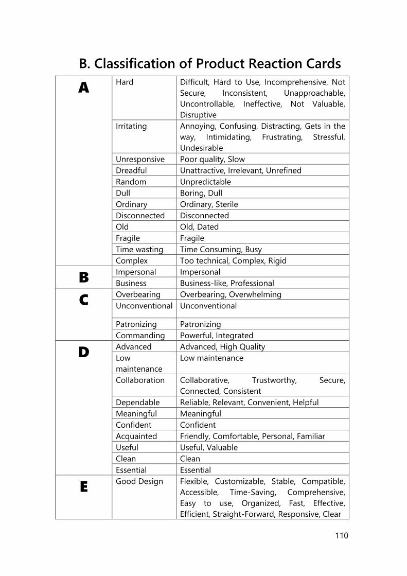
110
B. Classification of Product Reaction Cards
A Hard Difficult, Hard to Use, Incomprehensive, Not
Secure, Inconsistent, Unapproachable,
Uncontrollable, Ineffective, Not Valuable,
Disruptive
Irritating Annoying, Confusing, Distracting, Gets in the
way, Intimidating, Frustrating, Stressful,
Undesirable
Unresponsive Poor quality, Slow
Dreadful Unattractive, Irrelevant, Unrefined
Random Unpredictable
Dull Boring, Dull
Ordinary Ordinary, Sterile
Disconnected Disconnected
Old Old, Dated
Fragile Fragile
Time wasting Time Consuming, Busy
Complex Too technical, Complex, Rigid
B Impersonal Impersonal
Business Business-like, Professional
C Overbearing Overbearing, Overwhelming
Unconventional Unconventional
Patronizing Patronizing
Commanding Powerful, Integrated
D Advanced Advanced, High Quality
Low
maintenance
Low maintenance
Collaboration Collaborative, Trustworthy, Secure,
Connected, Consistent
Dependable Reliable, Relevant, Convenient, Helpful
Meaningful Meaningful
Confident Confident
Acquainted Friendly, Comfortable, Personal, Familiar
Useful Useful, Valuable
Clean Clean
Essential Essential
E Good Design Flexible, Customizable, Stable, Compatible,
Accessible, Time-Saving, Comprehensive,
Easy to use, Organized, Fast, Effective,
Efficient, Straight-Forward, Responsive, Clear
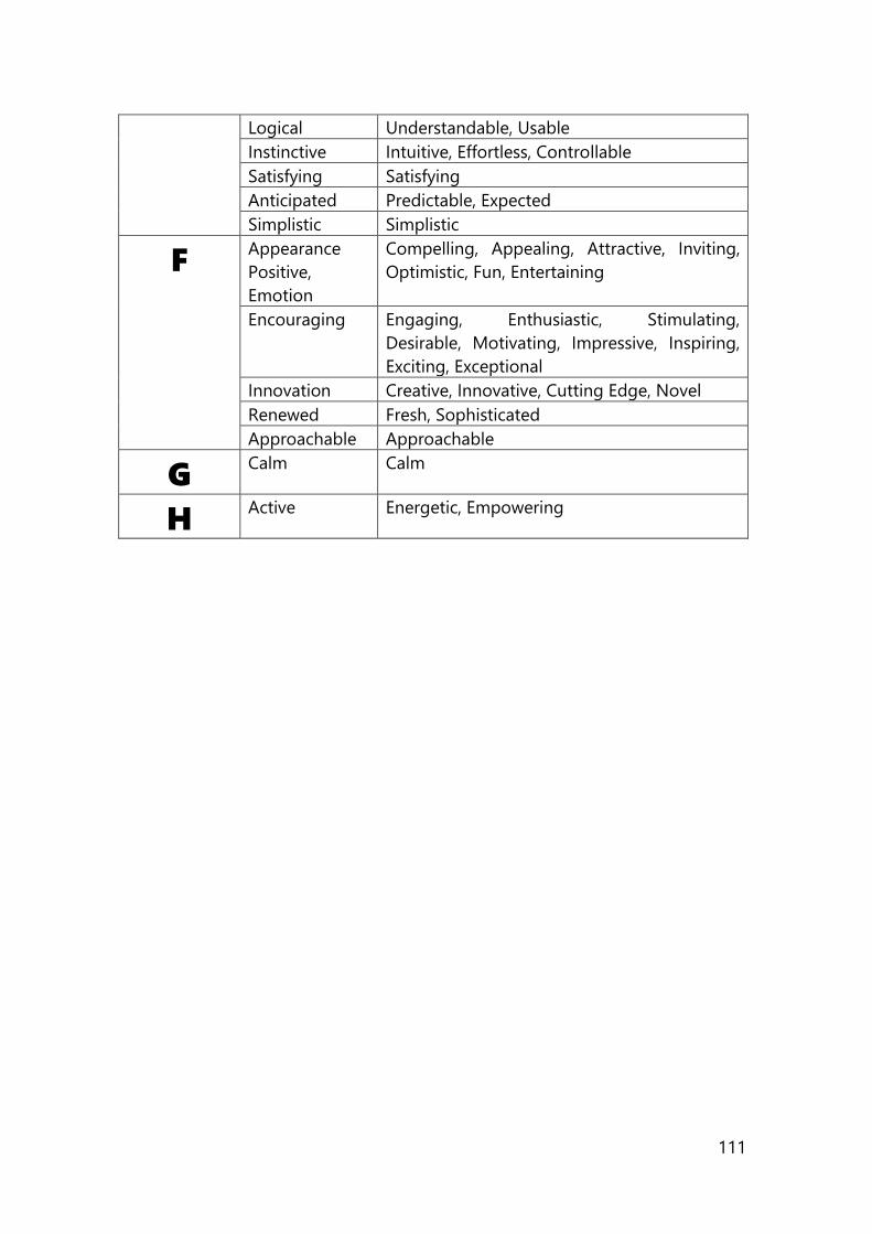
111
Logical Understandable, Usable
Instinctive Intuitive, Effortless, Controllable
Satisfying Satisfying
Anticipated Predictable, Expected
Simplistic Simplistic
F Appearance
Positive,
Emotion
Compelling, Appealing, Attractive, Inviting,
Optimistic, Fun, Entertaining
Encouraging Engaging, Enthusiastic, Stimulating,
Desirable, Motivating, Impressive, Inspiring,
Exciting, Exceptional
Innovation Creative, Innovative, Cutting Edge, Novel
Renewed Fresh, Sophisticated
Approachable Approachable
G Calm Calm
H Active Energetic, Empowering
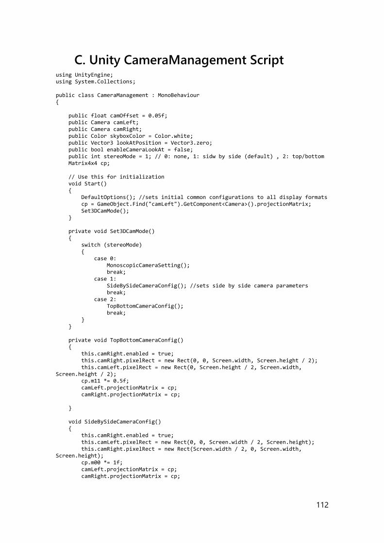
112
C. Unity CameraManagement Script using UnityEngine; using System.Collections; public class CameraManagement : MonoBehaviour { public float camOffset = 0.05f; public Camera camLeft; public Camera camRight; public Color skyboxColor = Color.white; public Vector3 lookAtPosition = Vector3.zero; public bool enableCameraLookAt = false; public int stereoMode = 1; // 0: none, 1: sidw by side (default) , 2: top/bottom Matrix4x4 cp; // Use this for initialization void Start() { DefaultOptions(); //sets initial common configurations to all display formats cp = GameObject.Find("camLeft").GetComponent<Camera>().projectionMatrix; Set3DCamMode(); } private void Set3DCamMode() { switch (stereoMode) { case 0: MonoscopicCameraSetting(); break; case 1: SideBySideCameraConfig(); //sets side by side camera parameters break; case 2: TopBottomCameraConfig(); break; } } private void TopBottomCameraConfig() { this.camRight.enabled = true; this.camRight.pixelRect = new Rect(0, 0, Screen.width, Screen.height / 2); this.camLeft.pixelRect = new Rect(0, Screen.height / 2, Screen.width, Screen.height / 2); cp.m11 *= 0.5f; camLeft.projectionMatrix = cp; camRight.projectionMatrix = cp; } void SideBySideCameraConfig() { this.camRight.enabled = true; this.camLeft.pixelRect = new Rect(0, 0, Screen.width / 2, Screen.height); this.camRight.pixelRect = new Rect(Screen.width / 2, 0, Screen.width, Screen.height); cp.m00 *= 1f; camLeft.projectionMatrix = cp; camRight.projectionMatrix = cp;
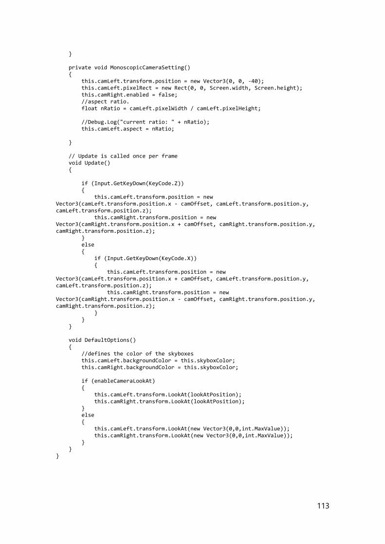
113
} private void MonoscopicCameraSetting() { this.camLeft.transform.position = new Vector3(0, 0, -40); this.camLeft.pixelRect = new Rect(0, 0, Screen.width, Screen.height); this.camRight.enabled = false; //aspect ratio. float nRatio = camLeft.pixelWidth / camLeft.pixelHeight; //Debug.Log("current ratio: " + nRatio); this.camLeft.aspect = nRatio; } // Update is called once per frame void Update() { if (Input.GetKeyDown(KeyCode.Z)) { this.camLeft.transform.position = new Vector3(camLeft.transform.position.x - camOffset, camLeft.transform.position.y, camLeft.transform.position.z); this.camRight.transform.position = new Vector3(camRight.transform.position.x + camOffset, camRight.transform.position.y, camRight.transform.position.z); } else { if (Input.GetKeyDown(KeyCode.X)) { this.camLeft.transform.position = new Vector3(camLeft.transform.position.x + camOffset, camLeft.transform.position.y, camLeft.transform.position.z); this.camRight.transform.position = new Vector3(camRight.transform.position.x - camOffset, camRight.transform.position.y, camRight.transform.position.z); } } } void DefaultOptions() { //defines the color of the skyboxes this.camLeft.backgroundColor = this.skyboxColor; this.camRight.backgroundColor = this.skyboxColor; if (enableCameraLookAt) { this.camLeft.transform.LookAt(lookAtPosition); this.camRight.transform.LookAt(lookAtPosition); } else { this.camLeft.transform.LookAt(new Vector3(0,0,int.MaxValue)); this.camRight.transform.LookAt(new Vector3(0,0,int.MaxValue)); } } }
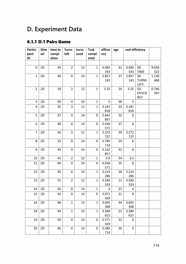
114
D. Experiment Data
6.1.1 D.1 Pairs Game
Participant ID
Stimuli
time to completion
Turns left
turns used
Task completed
efficiency
age real efficiency
0 2D 49 2 12 1 4.083333
31 4.083333
SD TIME
9.650522
1 2D 40 0 14 1 2.857143
27 2.857143
SD TURNS LEFT:
1.130668
2 2D 39 2 12 1 3.25 24 3.25 SD EFFICIENCY
0.766347
3 2D 50 4 10 1 5 38 5
4 2D 35 3 11 1 3.181818
33 3.181818
5 2D 37 0 14 0 2.642857
32 0
6 2D 48 0 14 0 3.428571
27 0
7 2D 36 3 11 1 3.272727
39 3.272727
8 2D 53 0 14 0 3.785714
29 0
9 2D 44 0 14 0 3.142857
31 0
10 2D 42 2 12 1 3.5 34 3.5
11 2D 69 0 14 0 4.928571
35 0
12 2D 45 0 14 1 3.214286
28 3.214286
13 2D 55 2 12 1 4.583333
21 4.583333
14 2D 56 0 14 1 4 21 4
15 2D 43 0 14 0 3.071429
21 0
16 2D 48 1 13 1 3.692308
44 3.692308
18 2D 44 1 13 1 3.384615
21 3.384615
19 2D 50 0 14 0 3.571429
22 0
20 2D 46 0 14 0 3.285714
26 0
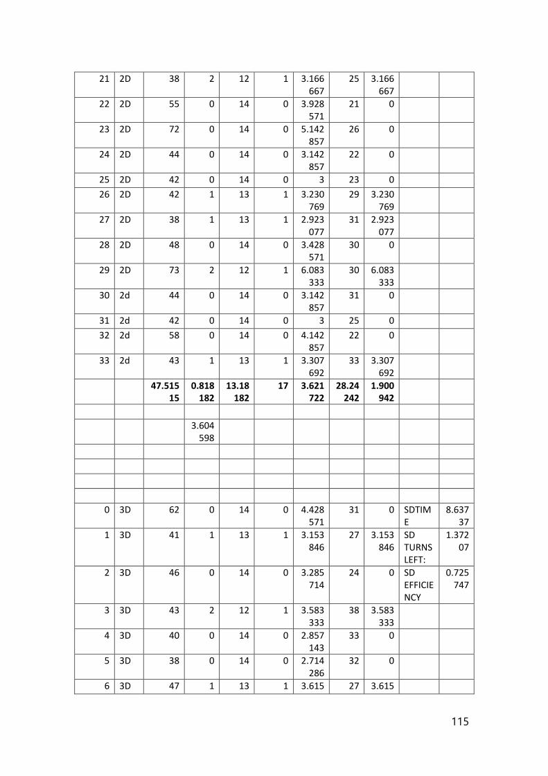
115
21 2D 38 2 12 1 3.166667
25 3.166667
22 2D 55 0 14 0 3.928571
21 0
23 2D 72 0 14 0 5.142857
26 0
24 2D 44 0 14 0 3.142857
22 0
25 2D 42 0 14 0 3 23 0
26 2D 42 1 13 1 3.230769
29 3.230769
27 2D 38 1 13 1 2.923077
31 2.923077
28 2D 48 0 14 0 3.428571
30 0
29 2D 73 2 12 1 6.083333
30 6.083333
30 2d 44 0 14 0 3.142857
31 0
31 2d 42 0 14 0 3 25 0
32 2d 58 0 14 0 4.142857
22 0
33 2d 43 1 13 1 3.307692
33 3.307692
47.51515
0.818182
13.18182
17 3.621722
28.24242
1.900942
3.604598
0 3D 62 0 14 0 4.428571
31 0 SDTIME
8.63737
1 3D 41 1 13 1 3.153846
27 3.153846
SD TURNS LEFT:
1.37207
2 3D 46 0 14 0 3.285714
24 0 SD EFFICIENCY
0.725747
3 3D 43 2 12 1 3.583333
38 3.583333
4 3D 40 0 14 0 2.857143
33 0
5 3D 38 0 14 0 2.714286
32 0
6 3D 47 1 13 1 3.615 27 3.615
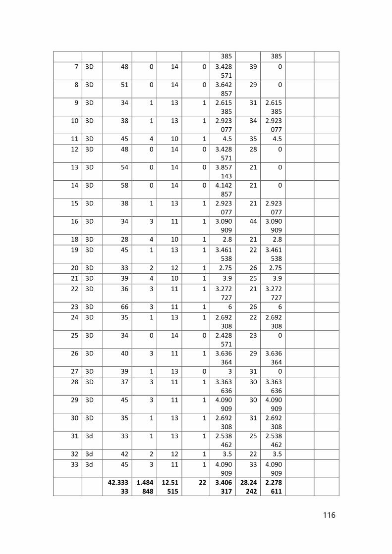
116
385 385
7 3D 48 0 14 0 3.428571
39 0
8 3D 51 0 14 0 3.642857
29 0
9 3D 34 1 13 1 2.615385
31 2.615385
10 3D 38 1 13 1 2.923077
34 2.923077
11 3D 45 4 10 1 4.5 35 4.5
12 3D 48 0 14 0 3.428571
28 0
13 3D 54 0 14 0 3.857143
21 0
14 3D 58 0 14 0 4.142857
21 0
15 3D 38 1 13 1 2.923077
21 2.923077
16 3D 34 3 11 1 3.090909
44 3.090909
18 3D 28 4 10 1 2.8 21 2.8
19 3D 45 1 13 1 3.461538
22 3.461538
20 3D 33 2 12 1 2.75 26 2.75
21 3D 39 4 10 1 3.9 25 3.9
22 3D 36 3 11 1 3.272727
21 3.272727
23 3D 66 3 11 1 6 26 6
24 3D 35 1 13 1 2.692308
22 2.692308
25 3D 34 0 14 0 2.428571
23 0
26 3D 40 3 11 1 3.636364
29 3.636364
27 3D 39 1 13 0 3 31 0
28 3D 37 3 11 1 3.363636
30 3.363636
29 3D 45 3 11 1 4.090909
30 4.090909
30 3D 35 1 13 1 2.692308
31 2.692308
31 3d 33 1 13 1 2.538462
25 2.538462
32 3d 42 2 12 1 3.5 22 3.5
33 3d 45 3 11 1 4.090909
33 4.090909
42.33333
1.484848
12.51515
22 3.406317
28.24242
2.278611
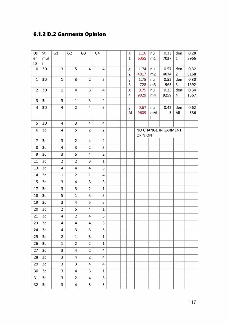
117
6.1.2 D.2 Garments Opinion
User ID
Stimuli
G1 G2 G3 G4 g1
1.166355
num1
0.337037
den1
0.288966
0 3D 3 5 4 4 g2
1.744017
num2
0.574074
den2
0.329168
1 3D 1 3 2 5 g3
1.75728
num3
0.52963
den3
0.301392
2 3D 1 4 3 4 g4
0.759029
num4
0.259259
den4
0.341567
3 3d 3 1 3 2
4 3D 4 2 4 3 gAll
0.679609
numAll
0.425
denAll
0.62536
5 3D 4 3 4 4
6 3d 4 5 2 2 NO CHANGE IN GARMENT OPINION
7 3d 3 2 4 2
8 3d 4 3 2 5
9 3d 3 5 4 2
11 3d 2 2 3 1
13 3d 4 4 4 3
14 3d 1 2 1 4
15 3d 3 4 3 3
17 3d 3 3 2 1
18 3d 5 1 3 3
19 3d 3 4 5 3
20 3d 2 5 4 1
21 3d 4 2 4 3
23 3d 4 4 4 3
24 3d 4 3 3 5
25 3d 2 1 3 1
26 3d 1 2 2 1
27 3d 3 4 2 4
28 3d 3 4 2 4
29 3d 3 3 4 4
30 3d 3 4 3 1
31 3d 3 2 4 5
32 3d 3 4 5 5
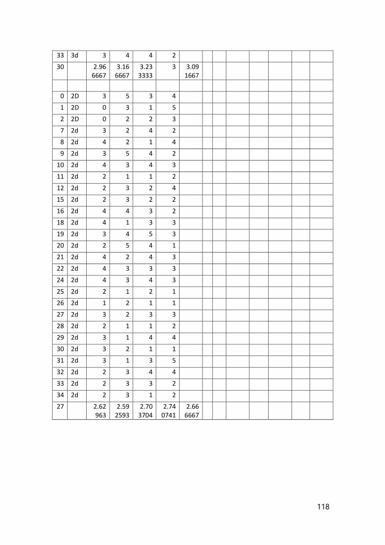
118
33 3d 3 4 4 2
30 2.966667
3.166667
3.233333
3 3.091667
0 2D 3 5 3 4
1 2D 0 3 1 5
2 2D 0 2 2 3
7 2d 3 2 4 2
8 2d 4 2 1 4
9 2d 3 5 4 2
10 2d 4 3 4 3
11 2d 2 1 1 2
12 2d 2 3 2 4
15 2d 2 3 2 2
16 2d 4 4 3 2
18 2d 4 1 3 3
19 2d 3 4 5 3
20 2d 2 5 4 1
21 2d 4 2 4 3
22 2d 4 3 3 3
24 2d 4 3 4 3
25 2d 2 1 2 1
26 2d 1 2 1 1
27 2d 3 2 3 3
28 2d 2 1 1 2
29 2d 3 1 4 4
30 2d 3 2 1 1
31 2d 3 1 3 5
32 2d 2 3 4 4
33 2d 2 3 3 2
34 2d 2 3 1 2
27 2.62963
2.592593
2.703704
2.740741
2.666667
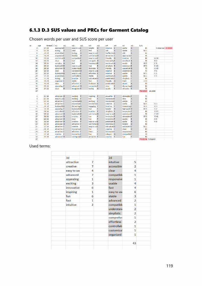
119
6.1.3 D.3 SUS values and PRCs for Garment Catalog
Chosen words per user and SUS score per user
Used terms:

120

121