Embed Size (px)
Citation preview

The g loba l leaderin p lumbing, heat ing
and p ipe jo in ing systems
Advanced Snow Melt ControlInstallation Manual
IM-PR 560642 1017 (Advanced Snow Melt Control)2
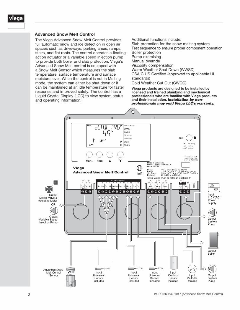
The Viega Advanced Snow Melt Control provides full automatic snow and ice detection in open air spaces such as driveways, parking areas, ramps, stairs, and flat roofs. The control operates a floating action actuator or a variable speed injection pump to provide both boiler and slab protection. Viega’s Advanced Snow Melt control is equipped with a Snow Melt Sensor which measures the slab temperature, surface temperature and surface moisture level. When the control is not in Melting mode, the system can either be shut down or it can be maintained at an idle temperature for faster response and improved safety. The control has a Liquid Crystal Display (LCD) to view system status and operating information.
Advanced Snow Melt ControlAdditional functions include:Slab protection for the snow melting system Test sequence to ensure proper component operationBoiler protection Pump exercisingManual overrideViscosity compensationWarm Weather Shut Down (WWSD)CSA C US Certified (approved to applicable UL standards)Cold Weather Cut Out (CWCO) Viega products are designed to be installed by licensed and trained plumbing and mechanical professionals who are familiar with Viega products and their installation. Installation by non-professionals may void Viega LLC’s warranty.
3IM-PR 560642 1017 (Advanced Snow Melt Control)
Contents
1 General operation 1.1 Description of display . . . . . . . . . . . . . . . . 4 1.2 Quick setup . . . . . . . . . . . . . . . . . . . . . . . . 5 1.3 Powering up the control . . . . . . . . . . . . . . 5 1.4 Mixing device selection . . . . . . . . . . . . . . . 5
2 Snow melting operation 2.1 Snow melting features . . . . . . . . . . . . . . . . 7 2.2 Snow melting demands . . . . . . . . . . . . . . 10 2.3 General melting operation . . . . . . . . . . . . 11 2.4 General idling operation . . . . . . . . . . . . . 12 2.5 View menu . . . . . . . . . . . . . . . . . . . . . . . . 13 2.6 Adjust menu . . . . . . . . . . . . . . . . . . . . . . 14 3 Installation 3.1 Mounting and rough-in . . . . . . . . . . . . . . 16 3.2 Sensor installation . . . . . . . . . . . . . . . . . . 17 3.3 Electrical connections . . . . . . . . . . . . . . . 18 3.4 Output connections . . . . . . . . . . . . . . . . . 19
4 Troubleshooting 4.1 Testing the wiring . . . . . . . . . . . . . . . . . . 22 4.2 Testing the sensors . . . . . . . . . . . . . . . . . 23 4.3 Testing the control . . . . . . . . . . . . . . . . . 24 4.4 Error messages . . . . . . . . . . . . . . . . . . . . 25
5 Wiring and piping diagrams . . . . . . . . . 27
6 Technical data . . . . . . . . . . . . . . . . . . . 30
Important Note: Proper operation is possible only if the Advanced Snow Melt Control System is installed and activated before there is frost or snow present. Snow melt area must be clean and dry at installation for proper system setup. We recommended that the system be left in operation during the entire heating season. Your system will work properly only if the heat load of the area under control has been calculated properly or the system has been adapted to the local conditions. Please contact your installer or local Viega representative for further information.
IM-PR 560642 1017 (Advanced Snow Melt Control)4
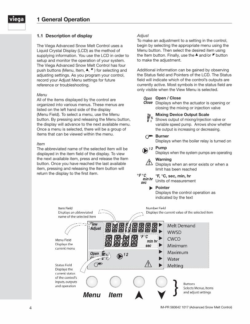
1.1 Description of display
The Viega Advanced Snow Melt Control uses a Liquid Crystal Display (LCD) as the method of supplying information. You use the LCD in order to setup and monitor the operation of your system. The Viega Advanced Snow Melt Control has four push buttons (Menu, Item, , ) for selecting and adjusting settings. As you program your control, record your Adjust Menu settings for future reference or troubleshooting.
MenuAll of the items displayed by the control are organized into various menus. These menus are listed on the left hand side of the display (Menu Field). To select a menu, use the Menu button. By pressing and releasing the Menu button, the display will advance to the next available menu. Once a menu is selected, there will be a group of items that can be viewed within the menu.
Item The abbreviated name of the selected item will be displayed in the item field of the display. To view the next available item, press and release the Item button. Once you have reached the last available item, pressing and releasing the Item button will return the display to the first item.
Open / CloseDisplays when the actuator is opening or closing the mixing or injection valve
Mixing Device Output ScaleShows output of mixing/injection valve or variable speed pump. Arrows show whether the output is increasing or decreasing.
Burner Displays when the boiler relay is turned on
Pump Displays when the system pumps are operating
WarningDisplays when an error exists or when a limit has been reached
°F, °C, sec, min, hr Units of measurement
Pointer Displays the control operation as indicated by the text
1 General Operation
Adjust
To make an adjustment to a setting in the control, begin by selecting the appropriate menu using the Menu button. Then select the desired item using the Item button. Finally, use the and/or button to make the adjustment.
Additional information can be gained by observing the Status field and Pointers of the LCD. The Status field will indicate which of the control’s outputs are currently active. Most symbols in the status field are only visible when the View Menu is selected.
5IM-PR 560642 1017 (Advanced Snow Melt Control)
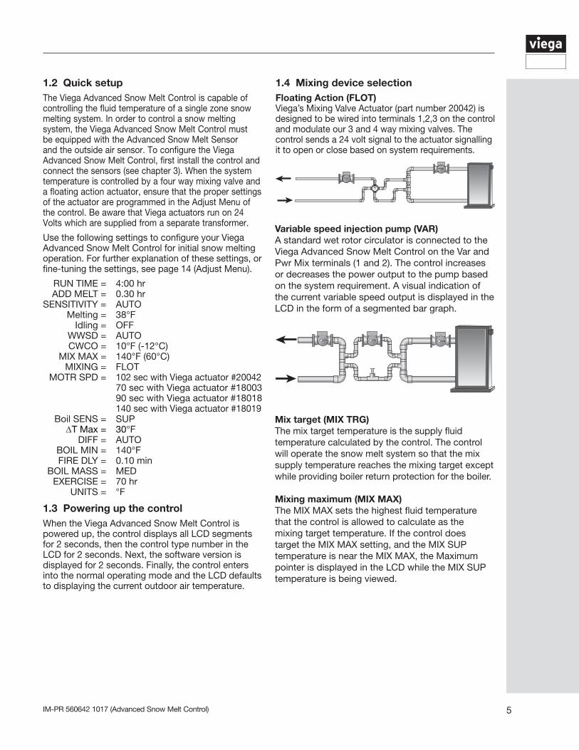
Variable speed injection pump (VAR)A standard wet rotor circulator is connected to the Viega Advanced Snow Melt Control on the Var and Pwr Mix terminals (1 and 2). The control increases or decreases the power output to the pump based on the system requirement. A visual indication of the current variable speed output is displayed in the LCD in the form of a segmented bar graph.
1.2 Quick setup The Viega Advanced Snow Melt Control is capable of controlling the fluid temperature of a single zone snow melting system. In order to control a snow melting system, the Viega Advanced Snow Melt Control must be equipped with the Advanced Snow Melt Sensor and the outside air sensor. To configure the Viega Advanced Snow Melt Control, first install the control and connect the sensors (see chapter 3). When the system temperature is controlled by a four way mixing valve and a floating action actuator, ensure that the proper settings of the actuator are programmed in the Adjust Menu of the control. Be aware that Viega actuators run on 24 Volts which are supplied from a separate transformer.
Use the following settings to configure your Viega Advanced Snow Melt Control for initial snow melting operation. For further explanation of these settings, or fine-tuning the settings, see page 14 (Adjust Menu).
RUN TIME = 4:00 hr ADD MELT = 0.30 hrSENSITIVITY = AUTO Melting = 38°F Idling = OFF WWSD = AUTO CWCO = 10°F (-12°C) MIX MAX = 140°F (60°C) MIXING = FLOT MOTR SPD = 102 sec with Viega actuator #20042 70 sec with Viega actuator #18003 90 sec with Viega actuator #18018 140 sec with Viega actuator #18019 Boil SENS = SUP ∆T Max = 30°F DIFF = AUTO BOIL MIN = 140°F FIRE DLY = 0.10 min BOIL MASS = MED EXERCISE = 70 hr UNITS = °F
1.3 Powering up the controlWhen the Viega Advanced Snow Melt Control is powered up, the control displays all LCD segments for 2 seconds, then the control type number in the LCD for 2 seconds. Next, the software version is displayed for 2 seconds. Finally, the control enters into the normal operating mode and the LCD defaults to displaying the current outdoor air temperature.
Mix target (MIX TRG)The mix target temperature is the supply fluid temperature calculated by the control. The control will operate the snow melt system so that the mix supply temperature reaches the mixing target except while providing boiler return protection for the boiler.
Mixing maximum (MIX MAX)The MIX MAX sets the highest fluid temperature that the control is allowed to calculate as the mixing target temperature. If the control does target the MIX MAX setting, and the MIX SUP temperature is near the MIX MAX, the Maximum pointer is displayed in the LCD while the MIX SUP temperature is being viewed.
1.4 Mixing device selectionFloating Action (FLOT)Viega’s Mixing Valve Actuator (part number 20042) is designed to be wired into terminals 1,2,3 on the control and modulate our 3 and 4 way mixing valves. The control sends a 24 volt signal to the actuator signalling it to open or close based on system requirements.
IM-PR 560642 1017 (Advanced Snow Melt Control)6
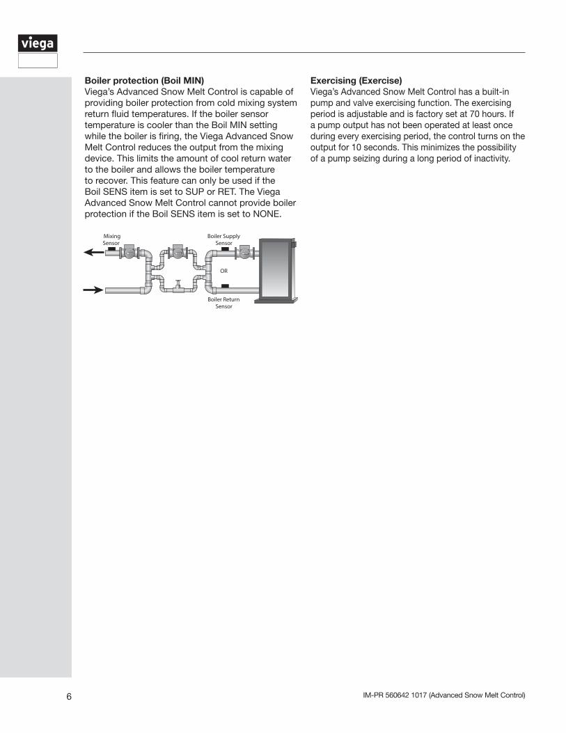
Boiler protection (Boil MIN)Viega’s Advanced Snow Melt Control is capable of providing boiler protection from cold mixing system return fluid temperatures. If the boiler sensor temperature is cooler than the Boil MIN setting while the boiler is firing, the Viega Advanced Snow Melt Control reduces the output from the mixing device. This limits the amount of cool return water to the boiler and allows the boiler temperature to recover. This feature can only be used if the Boil SENS item is set to SUP or RET. The Viega Advanced Snow Melt Control cannot provide boiler protection if the Boil SENS item is set to NONE.
Exercising (Exercise)Viega’s Advanced Snow Melt Control has a built-in pump and valve exercising function. The exercising period is adjustable and is factory set at 70 hours. If a pump output has not been operated at least once during every exercising period, the control turns on the output for 10 seconds. This minimizes the possibility of a pump seizing during a long period of inactivity.
7IM-PR 560642 1017 (Advanced Snow Melt Control)
2.1 Snow melting features
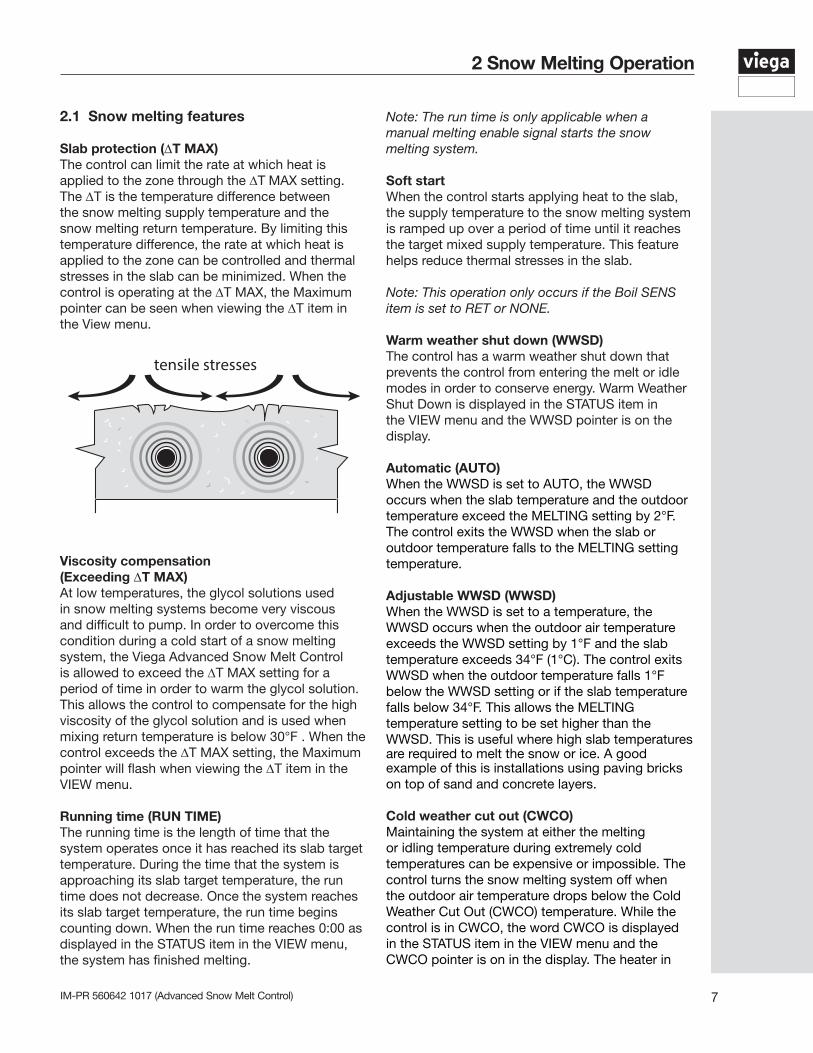
Slab protection (∆T MAX)The control can limit the rate at which heat is applied to the zone through the ∆T MAX setting. The ∆T is the temperature difference between the snow melting supply temperature and the snow melting return temperature. By limiting this temperature difference, the rate at which heat is applied to the zone can be controlled and thermal stresses in the slab can be minimized. When the control is operating at the ∆T MAX, the Maximum pointer can be seen when viewing the ∆T item in the View menu.
Viscosity compensation(Exceeding ∆T MAX)At low temperatures, the glycol solutions used in snow melting systems become very viscous and difficult to pump. In order to overcome this condition during a cold start of a snow melting system, the Viega Advanced Snow Melt Control is allowed to exceed the ∆T MAX setting for a period of time in order to warm the glycol solution. This allows the control to compensate for the high viscosity of the glycol solution and is used when mixing return temperature is below 30°F . When the control exceeds the ∆T MAX setting, the Maximum pointer will flash when viewing the ∆T item in the VIEW menu.
Running time (RUN TIME)The running time is the length of time that the system operates once it has reached its slab target temperature. During the time that the system is approaching its slab target temperature, the run time does not decrease. Once the system reaches its slab target temperature, the run time begins counting down. When the run time reaches 0:00 as displayed in the STATUS item in the VIEW menu, the system has finished melting.
2 Snow Melting Operation
Note: The run time is only applicable when a manual melting enable signal starts the snow melting system.
Soft startWhen the control starts applying heat to the slab, the supply temperature to the snow melting system is ramped up over a period of time until it reaches the target mixed supply temperature. This feature helps reduce thermal stresses in the slab.
Note: This operation only occurs if the Boil SENS item is set to RET or NONE.
Warm weather shut down (WWSD)The control has a warm weather shut down that prevents the control from entering the melt or idle modes in order to conserve energy. Warm Weather Shut Down is displayed in the STATUS item in the VIEW menu and the WWSD pointer is on the display. Automatic (AUTO)When the WWSD is set to AUTO, the WWSD occurs when the slab temperature and the outdoor temperature exceed the MELTING setting by 2°F. The control exits the WWSD when the slab or outdoor temperature falls to the MELTING setting temperature.
Adjustable WWSD (WWSD)When the WWSD is set to a temperature, the WWSD occurs when the outdoor air temperature exceeds the WWSD setting by 1°F and the slab temperature exceeds 34°F (1°C). The control exits WWSD when the outdoor temperature falls 1°F below the WWSD setting or if the slab temperature falls below 34°F. This allows the MELTING temperature setting to be set higher than the WWSD. This is useful where high slab temperatures are required to melt the snow or ice. A good example of this is installations using paving bricks on top of sand and concrete layers.
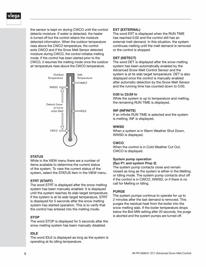
Cold weather cut out (CWCO)Maintaining the system at either the melting or idling temperature during extremely cold temperatures can be expensive or impossible. The control turns the snow melting system off when the outdoor air temperature drops below the Cold Weather Cut Out (CWCO) temperature. While the control is in CWCO, the word CWCO is displayed in the STATUS item in the VIEW menu and the CWCO pointer is on in the display. The heater in
IM-PR 560642 1017 (Advanced Snow Melt Control)8
STATUSWhile in the VIEW menu there are a number of items available to determine the current status of the system. To view the current status of the system, select the STATUS item in the VIEW menu.
STRT (START)The word STRT is displayed after the snow melting system has been manually enabled. It is displayed until the system reaches its slab target temperature. If the system is at its slab target temperature, STRT is displayed for 5 seconds after the snow melting system has started operation. This is to verify that the control has entered into the melting mode.
STOPThe word STOP is displayed for 5 seconds after the snow melting system has been manually disabled.
IDLEThe word IDLE is displayed as long as the system is operating at its idling temperature.
the sensor is kept on during CWCO until the control detects moisture. If water is detected, the heater is turned off but the control retains the moisture detected information. When the outdoor temperature rises above the CWCO temperature, the control exits CWCO and if the Snow Melt Sensor detected moisture during CWCO, the control initiates melting mode. If the control has been started prior to the CWCO, it resumes the melting mode once the outdoor air temperature rises above the CWCO temperature.
EXT (EXTERNAL)The word EXT is displayed when the RUN TIME has reached 0:00 and the control still has an external melt demand. In this situation, the system continues melting until the melt demand is removed or the control is stopped.
DET (DETECT)The word DET is displayed after the snow melting system has been automatically enabled by the Advanced Snow Melt Control Sensor and the system is at its slab target temperature. DET is also displayed once the control is manually enabled after automatic detection by the Snow Melt Sensor and the running time has counted down to 0:00.
0:00 to 23:59 hrWhile the system is up to temperature and melting, the remaining RUN TIME is displayed.
INF (INFINITE)If an infinite RUN TIME is selected and the system is melting, INF is displayed.
WWSDWhen a system is in Warm Weather Shut Down, WWSD is displayed.
CWCOWhen the control is in Cold Weather Cut Out, CWCO is displayed.
System pump operation(Sys P1 and system Pmp 2)The system pump contacts close and remain closed as long as the system is either in the Melting or Idling mode. The system pump contacts shut off if the control is in CWCO, WWSD, or if there is no call for Melting or Idling.
PURGEThe system pumps continue to operate for up to 2 minutes after the last demand is removed. This purges the residual heat from the boiler into the snow melting slab. If the boiler temperature drops below the Boil MIN setting after 20 seconds, the purge is aborted and the system pumps are turned off.
9IM-PR 560642 1017 (Advanced Snow Melt Control)
Boiler minimum (Boil MIN)The Boil MIN is the lowest water temperature that the control is allowed to use as a boiler target temperature. If the boiler is operating, and the boiler supply temperature is near the Boil MIN setting, the Minimum pointer turns on in the LCD while the Boil SUP temperature is being viewed. If the installed boiler is designed for condensing or low temperature operation, set the Boil MIN adjustment to OFF.
Fire delay (FIRE DLY)The FIRE DLY is the delay time that may occur between the time that the control closes the boiler contact and when the burner fires. This delay is usually the result of burner pre-purge or other forms of time delay built into the burner’s safety circuits.
Boiler mass (BOIL MASS)The BOIL MASS setting allows the Viega Advanced Snow Melt Control to adjust to different types of heat sources depending on their thermal mass.
Light (LITE)The LITE setting is selected if the boiler that is used has a low thermal mass. This means that the boiler has a very small water content and has very little metal in the heat exchanger. A boiler that has a low thermal mass comes up to temperature quite rapidly when fired. This is typical of many copper fin-tube boilers.
Medium (MED)The MED setting is selected if the boiler that is used has a medium thermal mass. This means that the boiler either has a large water content and a low metal content or a low water content and a high metal content. This is typical of many modern residential cast iron boilers or steel tube boilers.
Heavy (HEVY)The HEVY setting is selected if the boiler that is used has a high thermal mass. This means that the boiler has both a large water content and a large metal content. A boiler that has a high thermal mass is relatively slow in coming up to temperature. This is typical of many commercial cast iron and steel tube boilers.
Differential (DIFF)An on/off heat source such as a boiler must be operated with a differential in order to prevent short cycling. With the Viega Advanced Snow Melt Control either a fixed or an automatic differential may be selected.
Fixed differential The differential is centered round the target temperature. If the temperature drops ½ the differential below the target temperature, the Viega Advanced Snow Melt Control closes the boiler contact to fire the boiler. If the temperature rises ½ of the differential above the target temperature, the control opens the boiler contact to turn off the boiler.
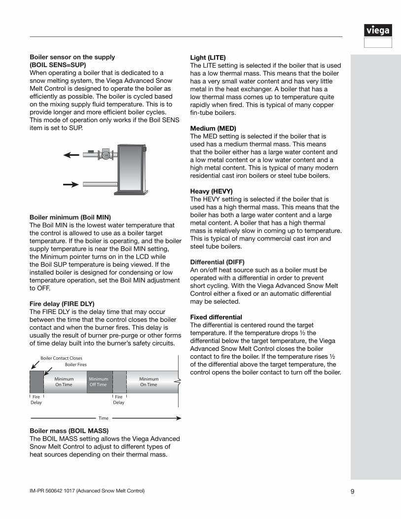
Boiler sensor on the supply(BOIL SENS=SUP)When operating a boiler that is dedicated to a snow melting system, the Viega Advanced Snow Melt Control is designed to operate the boiler as efficiently as possible. The boiler is cycled based on the mixing supply fluid temperature. This is to provide longer and more efficient boiler cycles. This mode of operation only works if the Boil SENS item is set to SUP.
IM-PR 560642 1017 (Advanced Snow Melt Control)10
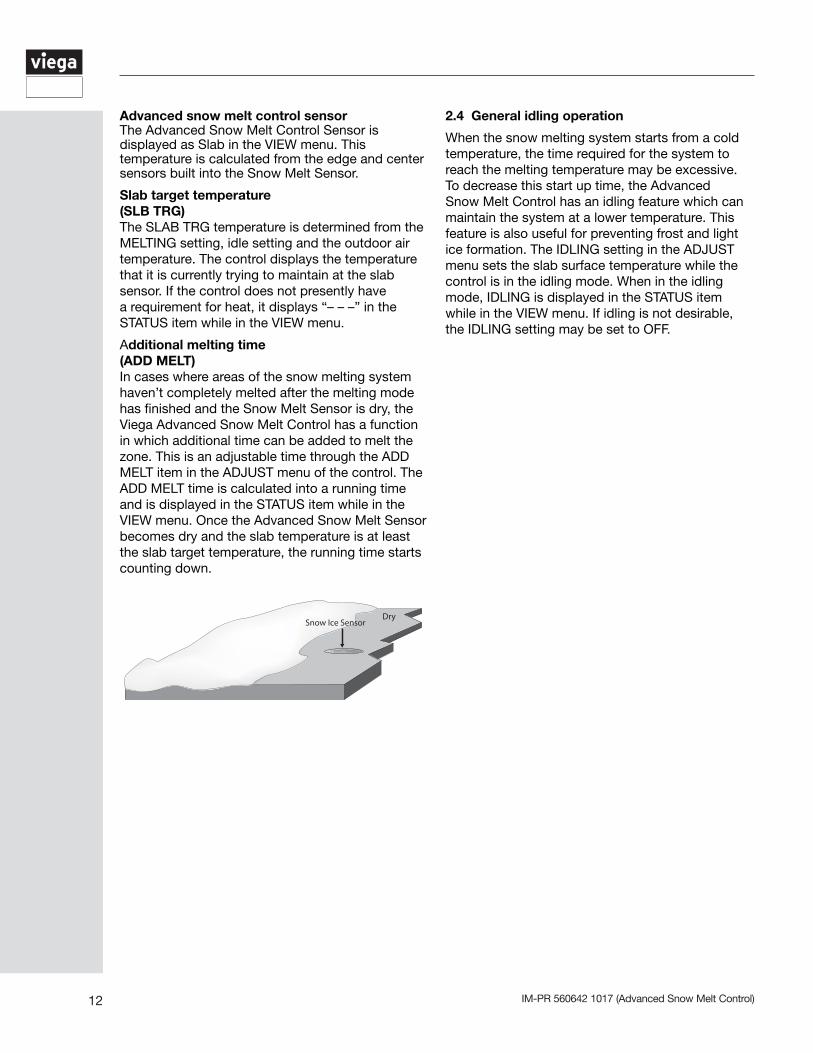
No boiler sensor(BOIL SENS = NONE)The Viega Advanced Snow Melt Control is capable of operating without a Boiler Sensor if desired. Without a Boiler Sensor, the Viega Advanced Snow Melt Control is unable to provide boiler protection. In this mode of operation, the boiler contact is used to provide a boiler enable. When the mixing device begins to ramp up, the boiler contact on the Viega Advanced Snow Melt Control closes. The boiler contact remains closed until the mixing device no longer requires heat. This type of application is typical if the Advanced Snow Melt Control is drawing heat from a source that already incorporates some form of boiler protection.
2.2 Snow melting demands
Snow melting enableThe snow melting system can be enabled manually or automatically. A melting enable signal applied to the control places the system into the melting mode. If a melting enable signal is applied once the system is already in the melting mode, the control responds to the last command received.
Manual melting enableA manual melting enable signal requires the user to manually start the snow melting system and can be provided from an external melt demand.
External melt demandThe snow melting system is enabled when a voltage between 24 and 230 V(AC) is applied across the Melt Demand terminals (16 and 17). An external melt demand must be present for at least 4 seconds in order to start the snow melting system. If the RUN TIME reaches 0:00 and the external melt demand is still present, the control continues melting until the external melt demand is removed or the system is otherwise stopped.
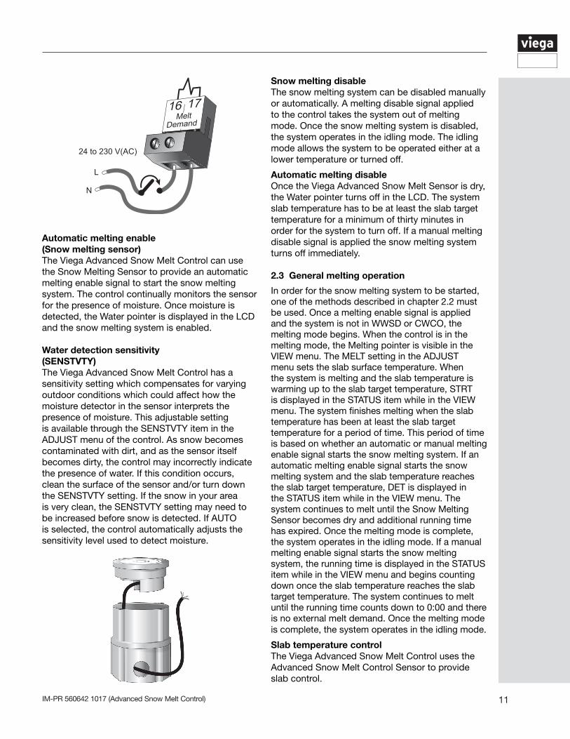
Boiler sensor on the return(BOIL SENS = RET)The boiler sensor should be located on the boiler return if the Viega Advanced Snow Melt Control is one of many controls that can call for boiler operation. When in the return mode, the control provides a boiler enable through the boiler contact. The control no longer tries to control the boiler supply water temperature directly, but allows the boiler to operate at its operating aquastat setting when required. When the mixing device begins to ramp up, the boiler contact closes on the control. The boiler contact remains closed until the mixing device no longer requires heat. With the sensor on the boiler return, the Advanced Snow Melt Control is still capable of providing boiler protection.
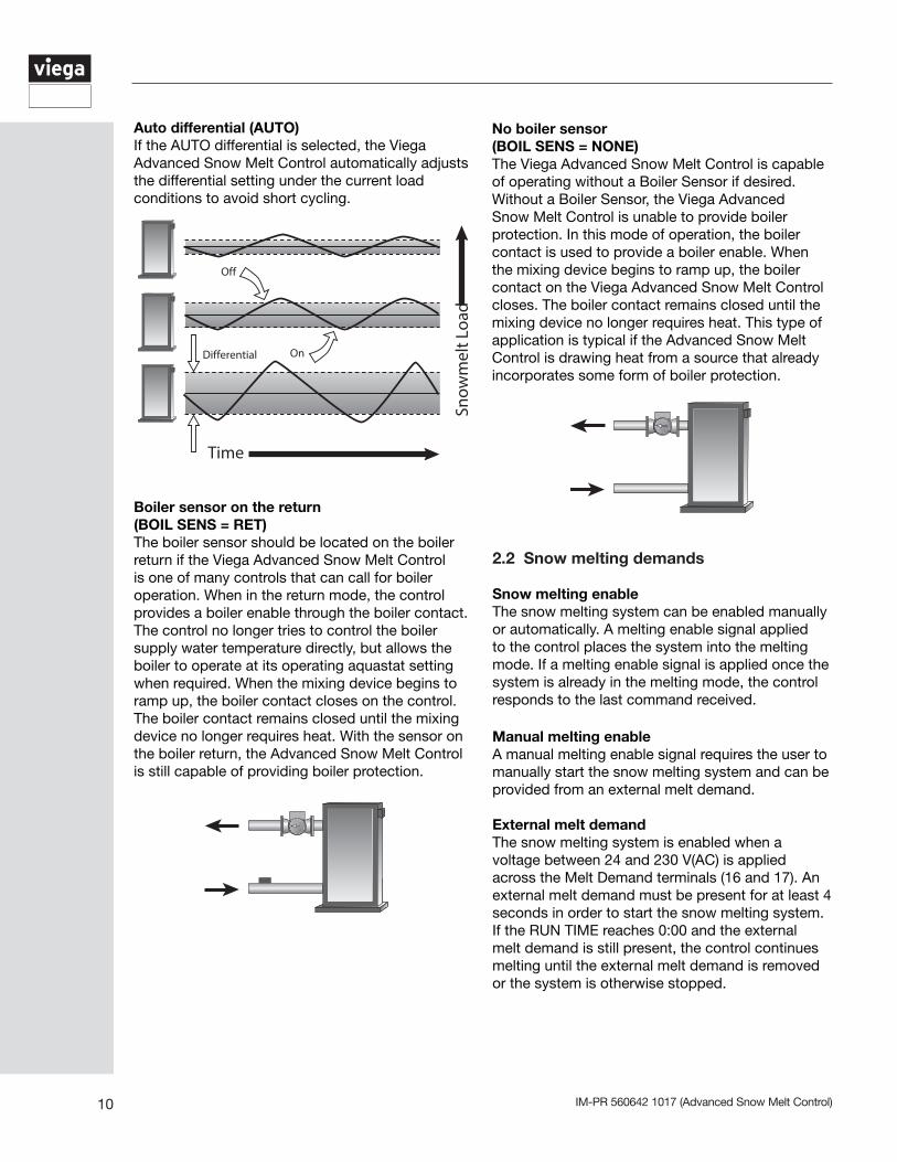
Auto differential (AUTO) If the AUTO differential is selected, the Viega Advanced Snow Melt Control automatically adjusts the differential setting under the current load conditions to avoid short cycling.
11IM-PR 560642 1017 (Advanced Snow Melt Control)
Automatic melting enable(Snow melting sensor)The Viega Advanced Snow Melt Control can use the Snow Melting Sensor to provide an automatic melting enable signal to start the snow melting system. The control continually monitors the sensor for the presence of moisture. Once moisture is detected, the Water pointer is displayed in the LCD and the snow melting system is enabled.
Water detection sensitivity(SENSTVTY)The Viega Advanced Snow Melt Control has a sensitivity setting which compensates for varying outdoor conditions which could affect how the moisture detector in the sensor interprets the presence of moisture. This adjustable setting is available through the SENSTVTY item in the ADJUST menu of the control. As snow becomes contaminated with dirt, and as the sensor itself becomes dirty, the control may incorrectly indicate the presence of water. If this condition occurs, clean the surface of the sensor and/or turn down the SENSTVTY setting. If the snow in your area is very clean, the SENSTVTY setting may need to be increased before snow is detected. If AUTO is selected, the control automatically adjusts the sensitivity level used to detect moisture.
16 17Melt
Demand
24 to 230 V(AC)
N
L
Snow melting disableThe snow melting system can be disabled manually or automatically. A melting disable signal applied to the control takes the system out of melting mode. Once the snow melting system is disabled, the system operates in the idling mode. The idling mode allows the system to be operated either at a lower temperature or turned off.
Automatic melting disableOnce the Viega Advanced Snow Melt Sensor is dry, the Water pointer turns off in the LCD. The system slab temperature has to be at least the slab target temperature for a minimum of thirty minutes in order for the system to turn off. If a manual melting disable signal is applied the snow melting system turns off immediately.
2.3 General melting operation
In order for the snow melting system to be started, one of the methods described in chapter 2.2 must be used. Once a melting enable signal is applied and the system is not in WWSD or CWCO, the melting mode begins. When the control is in the melting mode, the Melting pointer is visible in the VIEW menu. The MELT setting in the ADJUST menu sets the slab surface temperature. When the system is melting and the slab temperature is warming up to the slab target temperature, STRT is displayed in the STATUS item while in the VIEW menu. The system finishes melting when the slab temperature has been at least the slab target temperature for a period of time. This period of time is based on whether an automatic or manual melting enable signal starts the snow melting system. If an automatic melting enable signal starts the snow melting system and the slab temperature reaches the slab target temperature, DET is displayed in the STATUS item while in the VIEW menu. The system continues to melt until the Snow Melting Sensor becomes dry and additional running time has expired. Once the melting mode is complete, the system operates in the idling mode. If a manual melting enable signal starts the snow melting system, the running time is displayed in the STATUS item while in the VIEW menu and begins counting down once the slab temperature reaches the slab target temperature. The system continues to melt until the running time counts down to 0:00 and there is no external melt demand. Once the melting mode is complete, the system operates in the idling mode.
Slab temperature controlThe Viega Advanced Snow Melt Control uses the Advanced Snow Melt Control Sensor to provide slab control.
IM-PR 560642 1017 (Advanced Snow Melt Control)12
2.4 General idling operation
When the snow melting system starts from a cold temperature, the time required for the system to reach the melting temperature may be excessive. To decrease this start up time, the Advanced Snow Melt Control has an idling feature which can maintain the system at a lower temperature. This feature is also useful for preventing frost and light ice formation. The IDLING setting in the ADJUST menu sets the slab surface temperature while the control is in the idling mode. When in the idling mode, IDLING is displayed in the STATUS item while in the VIEW menu. If idling is not desirable, the IDLING setting may be set to OFF.
Advanced snow melt control sensorThe Advanced Snow Melt Control Sensor is displayed as Slab in the VIEW menu. This temperature is calculated from the edge and center sensors built into the Snow Melt Sensor.
Slab target temperature (SLB TRG)The SLAB TRG temperature is determined from the MELTING setting, idle setting and the outdoor air temperature. The control displays the temperature that it is currently trying to maintain at the slab sensor. If the control does not presently have a requirement for heat, it displays “– – –” in the STATUS item while in the VIEW menu.
Additional melting time(ADD MELT)In cases where areas of the snow melting system haven’t completely melted after the melting mode has finished and the Snow Melt Sensor is dry, the Viega Advanced Snow Melt Control has a function in which additional time can be added to melt the zone. This is an adjustable time through the ADD MELT item in the ADJUST menu of the control. The ADD MELT time is calculated into a running time and is displayed in the STATUS item while in the VIEW menu. Once the Advanced Snow Melt Sensor becomes dry and the slab temperature is at least the slab target temperature, the running time starts counting down.
13IM-PR 560642 1017 (Advanced Snow Melt Control)
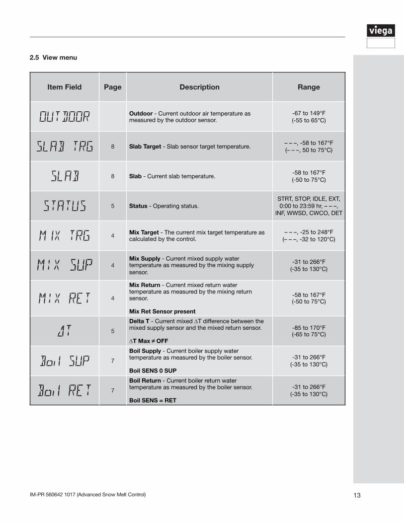
2.5 View menu
Item Field Page Description Range
Outdoor - Current outdoor air temperature as measured by the outdoor sensor.
-67 to 149°F(-55 to 65°C)
8 Slab Target - Slab sensor target temperature.– – –, -58 to 167°F(– – –, 50 to 75°C)
8 Slab - Current slab temperature.-58 to 167°F(-50 to 75°C)
5 Status - Operating status. STRT, STOP, IDLE, EXT,0:00 to 23:59 hr, – – –,
INF, WWSD, CWCO, DET
4 Mix Target - The current mix target temperature as calculated by the control.
– – –, -25 to 248°F(– – –, -32 to 120°C)
4Mix Supply - Current mixed supply water temperature as measured by the mixing supply sensor.
-31 to 266°F(-35 to 130°C)
4
Mix Return - Current mixed return water temperature as measured by the mixing return sensor.
Mix Ret Sensor present
-58 to 167°F(-50 to 75°C)
5
Delta T - Current mixed ∆T difference between the mixed supply sensor and the mixed return sensor.
∆T Max OFF
-85 to 170°F(-65 to 75°C)
7
Boil Supply - Current boiler supply water temperature as measured by the boiler sensor.
Boil SENS 0 SUP
-31 to 266°F(-35 to 130°C)
7
Boil Return - Current boiler return water temperature as measured by the boiler sensor.
Boil SENS = RET
-31 to 266°F(-35 to 130°C)
IM-PR 560642 1017 (Advanced Snow Melt Control)14
Item Field Page Description Range
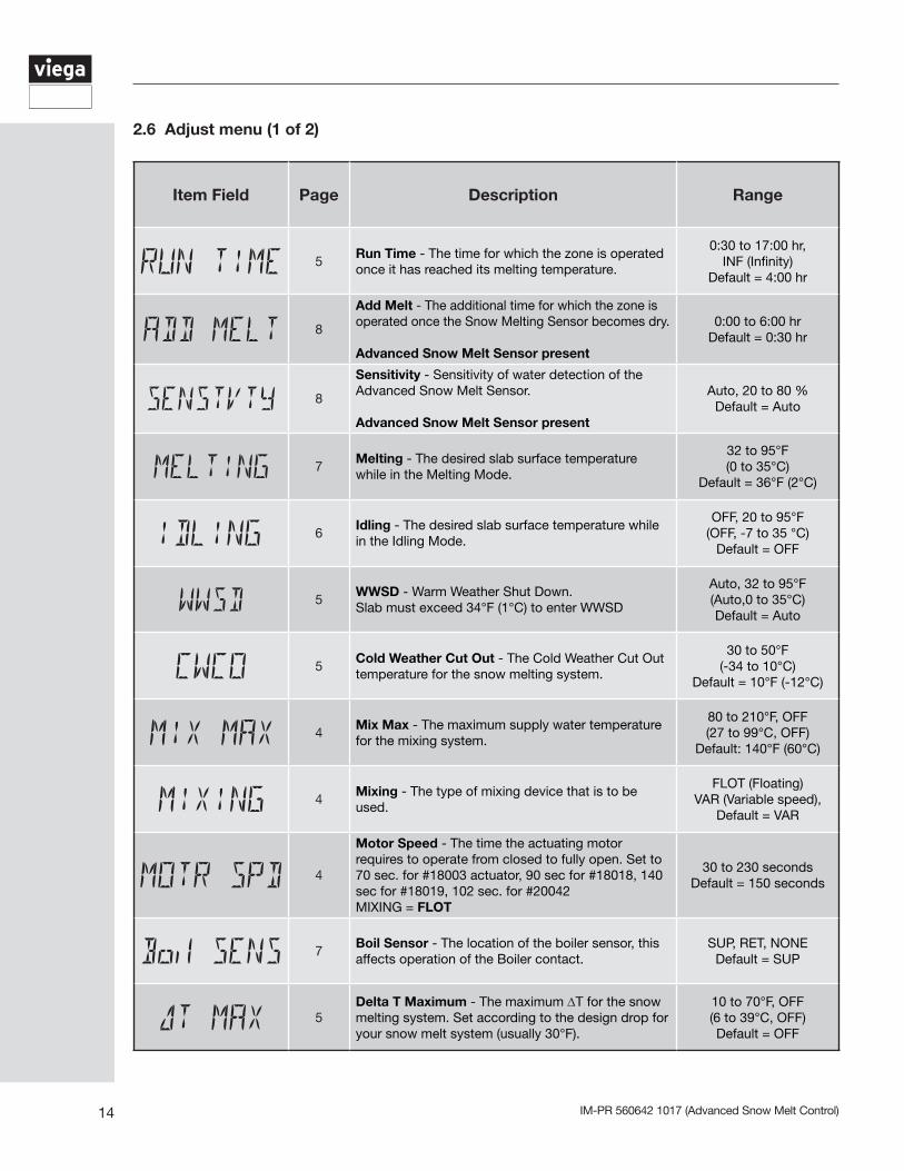
5Run Time - The time for which the zone is operated once it has reached its melting temperature.
0:30 to 17:00 hr,INF (Infinity)
Default = 4:00 hr
8
Add Melt - The additional time for which the zone is operated once the Snow Melting Sensor becomes dry.
Advanced Snow Melt Sensor present
0:00 to 6:00 hrDefault = 0:30 hr
8
Sensitivity - Sensitivity of water detection of the Advanced Snow Melt Sensor.
Advanced Snow Melt Sensor present
Auto, 20 to 80 %Default = Auto
7Melting - The desired slab surface temperature while in the Melting Mode.
32 to 95°F(0 to 35°C)
Default = 36°F (2°C)
6Idling - The desired slab surface temperature while in the Idling Mode.
OFF, 20 to 95°F(OFF, -7 to 35 °C)
Default = OFF
5WWSD - Warm Weather Shut Down. Slab must exceed 34°F (1°C) to enter WWSD
Auto, 32 to 95°F(Auto,0 to 35°C)Default = Auto
5Cold Weather Cut Out - The Cold Weather Cut Out temperature for the snow melting system.
30 to 50°F(-34 to 10°C)
Default = 10°F (-12°C)
4Mix Max - The maximum supply water temperature for the mixing system.
80 to 210°F, OFF(27 to 99°C, OFF)
Default: 140°F (60°C)
4Mixing - The type of mixing device that is to be used.
FLOT (Floating)VAR (Variable speed),
Default = VAR
4
Motor Speed - The time the actuating motor requires to operate from closed to fully open. Set to 70 sec. for #18003 actuator, 90 sec for #18018, 140 sec for #18019, 102 sec. for #20042MIXING = FLOT
30 to 230 secondsDefault = 150 seconds
7Boil Sensor - The location of the boiler sensor, this affects operation of the Boiler contact.
SUP, RET, NONEDefault = SUP
5Delta T Maximum - The maximum ∆T for the snow melting system. Set according to the design drop for your snow melt system (usually 30°F).
10 to 70°F, OFF(6 to 39°C, OFF)Default = OFF
2.6 Adjust menu (1 of 2)
15IM-PR 560642 1017 (Advanced Snow Melt Control)
Item Field Page Description Range
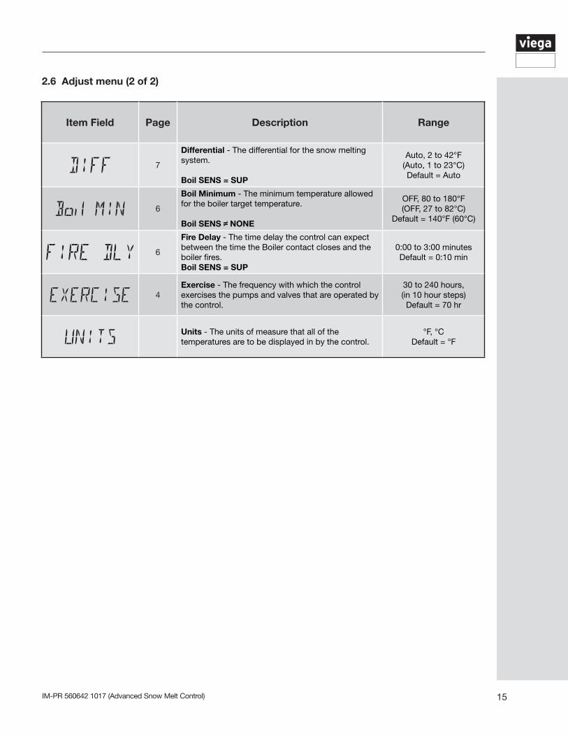
7
Differential - The differential for the snow melting system.
Boil SENS = SUP
Auto, 2 to 42°F(Auto, 1 to 23°C)Default = Auto
6
Boil Minimum - The minimum temperature allowed for the boiler target temperature.
Boil SENS NONE
OFF, 80 to 180°F(OFF, 27 to 82°C)
Default = 140°F (60°C)
6
Fire Delay - The time delay the control can expect between the time the Boiler contact closes and the boiler fires.Boil SENS = SUP
0:00 to 3:00 minutesDefault = 0:10 min
4Exercise - The frequency with which the control exercises the pumps and valves that are operated by the control.
30 to 240 hours,(in 10 hour steps)Default = 70 hr
Units - The units of measure that all of the temperatures are to be displayed in by the control.
°F, °CDefault = °F
2.6 Adjust menu (2 of 2)
IM-PR 560642 1017 (Advanced Snow Melt Control)16
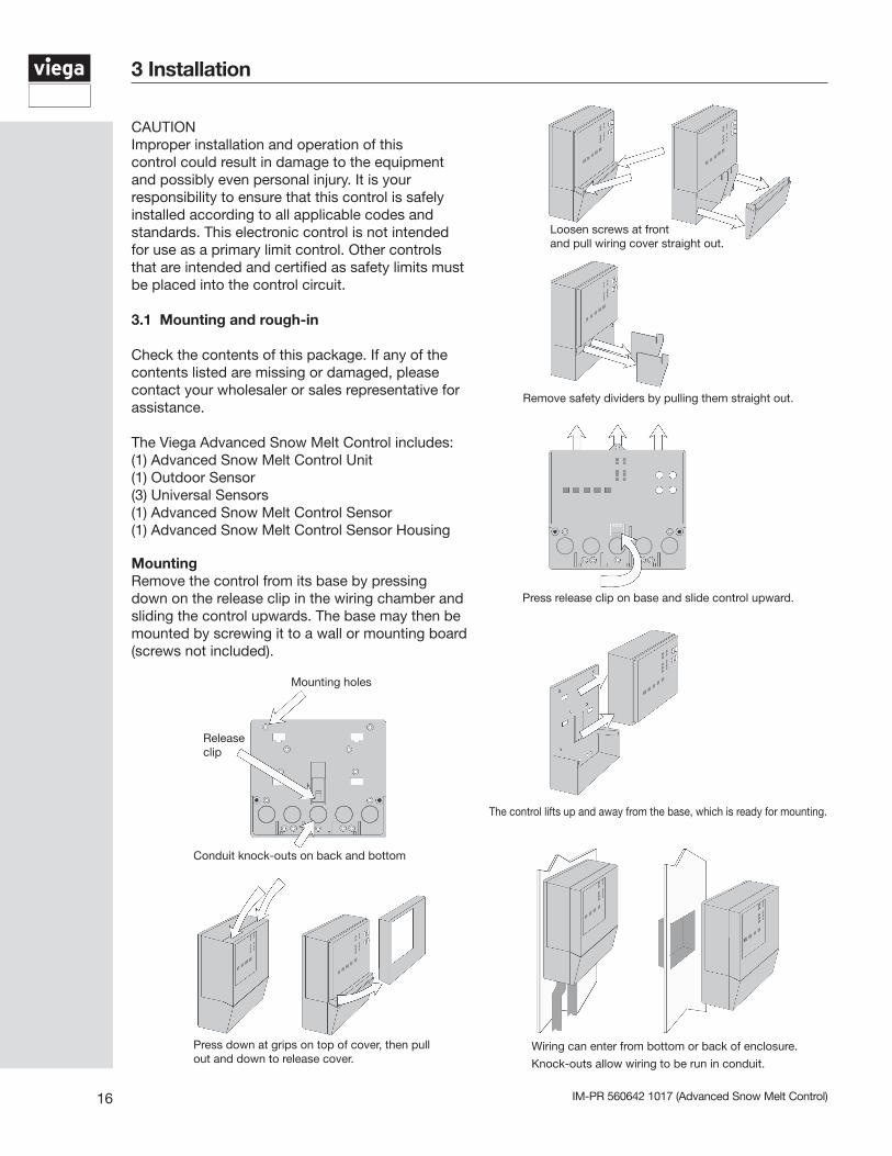
CAUTION Improper installation and operation of this control could result in damage to the equipment and possibly even personal injury. It is your responsibility to ensure that this control is safely installed according to all applicable codes and standards. This electronic control is not intended for use as a primary limit control. Other controls that are intended and certified as safety limits must be placed into the control circuit.
3.1 Mounting and rough-in
Check the contents of this package. If any of the contents listed are missing or damaged, please contact your wholesaler or sales representative for assistance.
The Viega Advanced Snow Melt Control includes: (1) Advanced Snow Melt Control Unit (1) Outdoor Sensor(3) Universal Sensors(1) Advanced Snow Melt Control Sensor (1) Advanced Snow Melt Control Sensor Housing
MountingRemove the control from its base by pressing down on the release clip in the wiring chamber and sliding the control upwards. The base may then be mounted by screwing it to a wall or mounting board (screws not included).
Press down at grips on top of cover, then pull out and down to release cover.
Loosen screws at front and pull wiring cover straight out.
Remove safety dividers by pulling them straight out.
Press release clip on base and slide control upward.
The control lifts up and away from the base, which is ready for mounting.
Wiring can enter from bottom or back of enclosure.
Knock-outs allow wiring to be run in conduit.
Mounting holes
Releaseclip
Conduit knock-outs on back and bottom
3 Installation
17IM-PR 560642 1017 (Advanced Snow Melt Control)
Rough-inAll electrical wiring terminates in the control base wiring chamber. The base has standard 7/8” (22mm) knockouts which accept common wiring hardware and conduit fittings. Before removing the knockouts, check the wiring diagram and select those sections of the chamber with common voltages. Do not allow the wiring to cross between sections as the wires will interfere with safety dividers which should be installed at a later time.
Power must not be applied to any of the wires during the rough-in wiring stage.• Install the Outdoor Sensor and the three universal sensors according to the instructions on page 17 and run the wiring back to the control.• Run wire from other system components (pump, boiler, actuating motor, etc.) to the control.• Run wires from the 120 V(AC) power to the control. Use a clean power source to ensure proper operation. Multi-strand 16 AWG wire is recommended for all 120 V(AC) wiring due to its superior flexibility and ease of installation into the terminals.
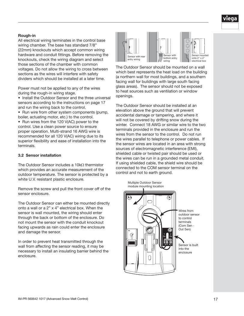
3.2 Sensor installation
The Outdoor Sensor includes a 10kΩthermistor which provides an accurate measurement of the outdoor temperature. The sensor is protected by a white U.V. resistant plastic enclosure.
Remove the screw and pull the front cover off of the sensor enclosure.
The Outdoor Sensor can either be mounted directly onto a wall or a 2” x 4” electrical box. When the sensor is wall mounted, the wiring should enter through the back or bottom of the enclosure. Do not mount the sensor with the conduit knockout facing upwards as rain could enter the enclosure and damage the sensor.
In order to prevent heat transmitted through the wall from affecting the sensor reading, it may be necessary to install an insulating barrier behind the enclosure.
The Outdoor Sensor should be mounted on a wall which best represents the heat load on the building (a northern wall for most buildings, and a southern facing wall for buildings with large south facing glass areas). The sensor should not be exposed to heat sources such as ventilation or window openings.
The Outdoor Sensor should be installed at an elevation above the ground that will prevent accidental damage or tampering, and where it will not be covered by drifting snow during the winter. Connect 18 AWG or similar wire to the two terminals provided in the enclosure and run the wires from the sensor to the control. Do not run the wires parallel to telephone or power cables. If the sensor wires are located in an area with strong sources of electromagnetic interference (EMI), shielded cable or twisted pair should be used or the wires can be run in a grounded metal conduit. If using shielded cable, the shield wire should be connected to the COM sensor terminal on the control and not to earth ground.
Multiple Outdoor Sensor module mounting location
Wires from outdoor sensor to control terminals(Com Sen - Out Sen)
Sensor is built into the enclosure
Sensor with rear entry wiring
Sensor with bottom entry wiring
Sensor mounted onto 2" x 4" electrical box
IM-PR 560642 1017 (Advanced Snow Melt Control)18
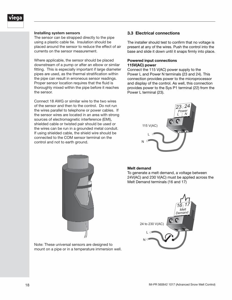
Installing system sensors The sensor can be strapped directly to the pipe using a plastic cable tie. Insulation should be placed around the sensor to reduce the effect of air currents on the sensor measurement.
Where applicable, the sensor should be placed downstream of a pump or after an elbow or similar fitting. This is especially important if large diameter pipes are used, as the thermal stratification within the pipe can result in erroneous sensor readings. Proper sensor location requires that the fluid is thoroughly mixed within the pipe before it reaches the sensor.
Connect 18 AWG or similar wire to the two wires of the sensor and then to the control. Do not run the wires parallel to telephone or power cables. If the sensor wires are located in an area with strong sources of electromagnetic interference (EMI), shielded cable or twisted pair should be used or the wires can be run in a grounded metal conduit. If using shielded cable, the shield wire should be connected to the COM sensor terminal on the control and not to earth ground.
3.3 Electrical connections
The installer should test to confirm that no voltage is present at any of the wires. Push the control into the base and slide it down until it snaps firmly into place.
Powered input connections115V(AC) powerConnect the 115 V(AC) power supply to the Power L and Power N terminals (23 and 24). This connection provides power to the microprocessor and display of the control. As well, this connection provides power to the Sys P1 terminal (22) from the Power L terminal (23).
Melt demandTo generate a melt demand, a voltage between 24V(AC) and 230 V(AC) must be applied across the Melt Demand terminals (16 and 17)
16 17Melt
Demand
24 to 230 V(AC)
N
L
Note: These universal sensors are designed to mount on a pipe or in a temperature immersion well.
19IM-PR 560642 1017 (Advanced Snow Melt Control)
3.4 Output connections
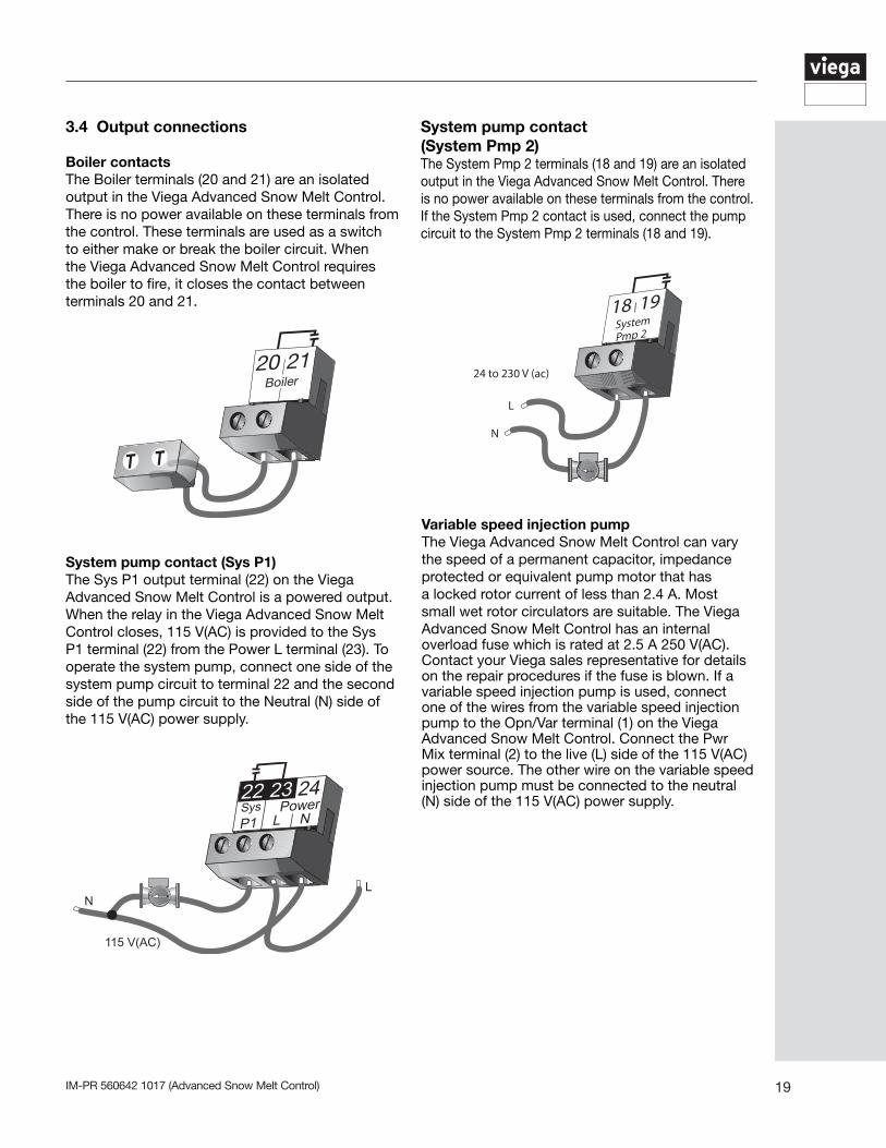
Boiler contactsThe Boiler terminals (20 and 21) are an isolated output in the Viega Advanced Snow Melt Control. There is no power available on these terminals from the control. These terminals are used as a switch to either make or break the boiler circuit. When the Viega Advanced Snow Melt Control requires the boiler to fire, it closes the contact between terminals 20 and 21.
System pump contact (Sys P1)The Sys P1 output terminal (22) on the Viega Advanced Snow Melt Control is a powered output. When the relay in the Viega Advanced Snow Melt Control closes, 115 V(AC) is provided to the Sys P1 terminal (22) from the Power L terminal (23). To operate the system pump, connect one side of the system pump circuit to terminal 22 and the second side of the pump circuit to the Neutral (N) side of the 115 V(AC) power supply.
Variable speed injection pumpThe Viega Advanced Snow Melt Control can vary the speed of a permanent capacitor, impedance protected or equivalent pump motor that has a locked rotor current of less than 2.4 A. Most small wet rotor circulators are suitable. The Viega Advanced Snow Melt Control has an internal overload fuse which is rated at 2.5 A 250 V(AC). Contact your Viega sales representative for details on the repair procedures if the fuse is blown. If a variable speed injection pump is used, connect one of the wires from the variable speed injection pump to the Opn/Var terminal (1) on the Viega Advanced Snow Melt Control. Connect the Pwr Mix terminal (2) to the live (L) side of the 115 V(AC) power source. The other wire on the variable speed injection pump must be connected to the neutral (N) side of the 115 V(AC) power supply.
System pump contact (System Pmp 2)The System Pmp 2 terminals (18 and 19) are an isolated output in the Viega Advanced Snow Melt Control. There is no power available on these terminals from the control. If the System Pmp 2 contact is used, connect the pump circuit to the System Pmp 2 terminals (18 and 19).
IM-PR 560642 1017 (Advanced Snow Melt Control)20
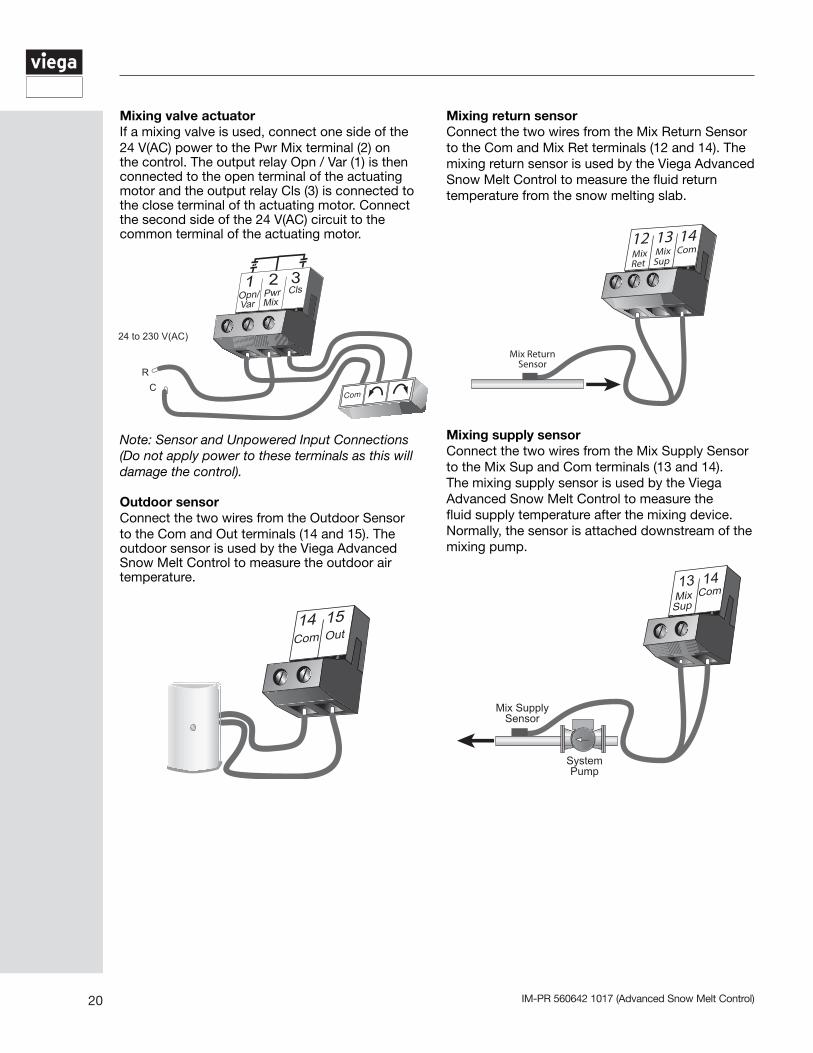
Mixing return sensorConnect the two wires from the Mix Return Sensor to the Com and Mix Ret terminals (12 and 14). The mixing return sensor is used by the Viega Advanced Snow Melt Control to measure the fluid return temperature from the snow melting slab.
Mixing supply sensorConnect the two wires from the Mix Supply Sensor to the Mix Sup and Com terminals (13 and 14). The mixing supply sensor is used by the Viega Advanced Snow Melt Control to measure the fluid supply temperature after the mixing device. Normally, the sensor is attached downstream of the mixing pump.
Mixing valve actuatorIf a mixing valve is used, connect one side of the 24 V(AC) power to the Pwr Mix terminal (2) on the control. The output relay Opn / Var (1) is then connected to the open terminal of the actuating motor and the output relay Cls (3) is connected to the close terminal of th actuating motor. Connect the second side of the 24 V(AC) circuit to the common terminal of the actuating motor.
Note: Sensor and Unpowered Input Connections (Do not apply power to these terminals as this will damage the control).
Outdoor sensorConnect the two wires from the Outdoor Sensor to the Com and Out terminals (14 and 15). The outdoor sensor is used by the Viega Advanced Snow Melt Control to measure the outdoor air temperature.
21IM-PR 560642 1017 (Advanced Snow Melt Control)
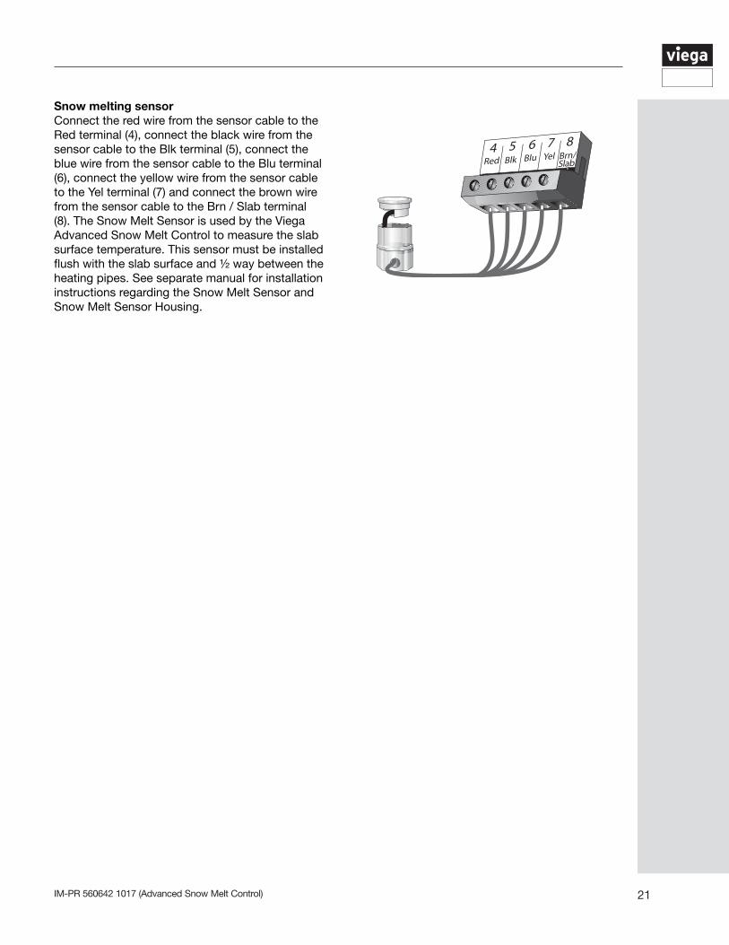
Snow melting sensorConnect the red wire from the sensor cable to the Red terminal (4), connect the black wire from the sensor cable to the Blk terminal (5), connect the blue wire from the sensor cable to the Blu terminal (6), connect the yellow wire from the sensor cable to the Yel terminal (7) and connect the brown wire from the sensor cable to the Brn / Slab terminal (8). The Snow Melt Sensor is used by the Viega Advanced Snow Melt Control to measure the slab surface temperature. This sensor must be installed flush with the slab surface and ½ way between the heating pipes. See separate manual for installation instructions regarding the Snow Melt Sensor and Snow Melt Sensor Housing.
IM-PR 560642 1017 (Advanced Snow Melt Control)22
Test the outputsSystem pump (System Pmp 2)If a pump is connected to the System Pmp 2 terminals (18 and 19), make sure power to the pump circuit is off and install a jumper between the System Pmp 2 terminals (18 and 19). When the circuit is powered up, the pump should turn on. If no response occurs, check the wiring between the terminal and the pump and refer to any installation or troubleshooting information supplied with the pump. If the pump operates properly disconnect the power and remove the jumper.
BoilerIf the boiler circuit is connected to the Boiler terminals (20 and 21), make sure power to the boiler circuit is off, and install a jumper between the terminals. When the boiler circuit is powered up, the boiler should fire. If the boiler does not turn on, refer to any installation or troubleshooting information supplied with the boiler. (The boiler may have a flow switch that prevents firing until the boiler pump is running). If the boiler operates properly, disconnect the power and remove the jumper.
Test the power inputs meltIf a Melt demand is used, measure the voltage between the Melt Demand terminals (16 and 17). When the melting or idling device calls for heat, you should measure between 20 and 260 V(AC) at the terminals. When the melting or idling device is off, you should measure less than 5 V(AC).
4.1 Testing the wiring
Each terminal block must be unplugged from its header on the control before power is applied for testing. To remove the terminal block, pull straight down from the control. The following tests are to be performed using standard testing practices and procedures and should only be carried out by properly trained and experienced persons. A good quality electrical test meter, capable of reading from at least 0 – 300 V(AC) and at least 0 – 2,000,000 W, is essential to properly test the wiring and sensors.
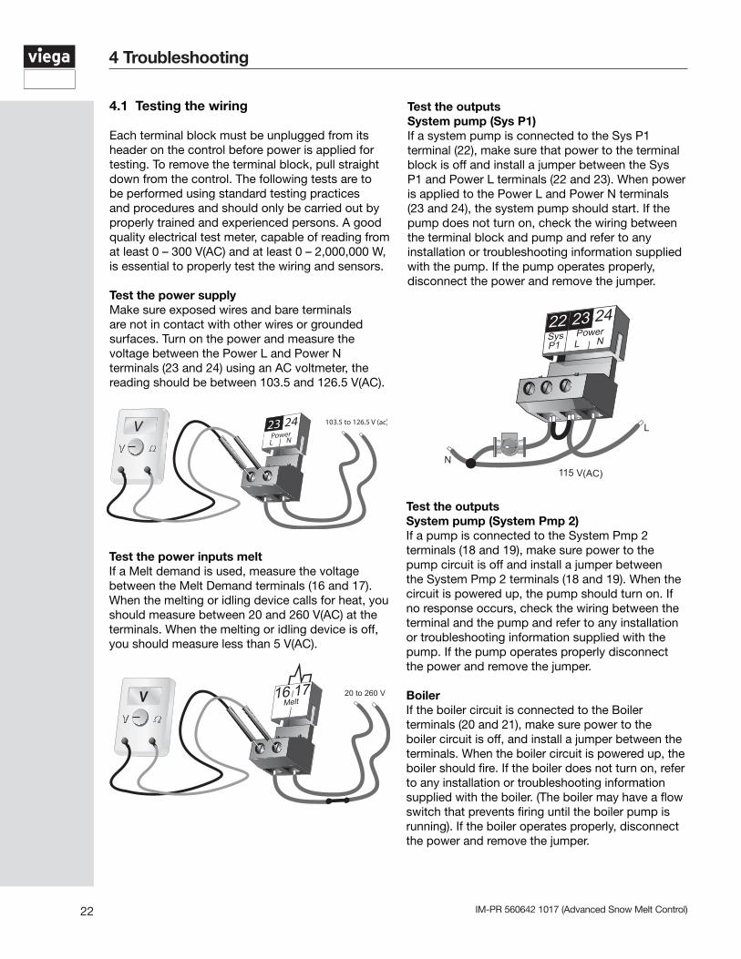
Test the power supplyMake sure exposed wires and bare terminals are not in contact with other wires or grounded surfaces. Turn on the power and measure the voltage between the Power L and Power N terminals (23 and 24) using an AC voltmeter, the reading should be between 103.5 and 126.5 V(AC).
Test the outputsSystem pump (Sys P1)If a system pump is connected to the Sys P1 terminal (22), make sure that power to the terminal block is off and install a jumper between the Sys P1 and Power L terminals (22 and 23). When power is applied to the Power L and Power N terminals (23 and 24), the system pump should start. If the pump does not turn on, check the wiring between the terminal block and pump and refer to any installation or troubleshooting information supplied with the pump. If the pump operates properly, disconnect the power and remove the jumper.
4 Troubleshooting
22 23 24SysP1
PowerNL
N
L
23IM-PR 560642 1017 (Advanced Snow Melt Control)
Variable speed injection pumpIf a variable speed injection pump circuit is connected to the Opn/Var and Pwr Mix terminals (1 and 2), make sure the power to the terminal block is off and install a jumper between the Opn/Var and Pwr Mix terminals (1 and 2). When the variable speed pump circuit is powered up, the variable speed pump should operate at full speed. If the pump does not operate, check the wiring between the terminal block and the pump and refer to any installation or troubleshooting information supplied with the pump. If the pump operates properly, disconnect the power and remove the jumper.
Mixing valve actuatorIf a floating action actuating motor circuit is connected to the Pwr Mix, Opn/Var and Cls terminals (2, 1 and 3), make sure power to the motor circuit is off and install a jumper between the Pwr Mix and Opn/Var terminals (2 and 1). When the circuit is powered up, the actuator should move in the opening direction. If it does not, check the wiring between the terminals and the actuating motor. Refer to any installation or trouble-shooting information supplied with the motor. If the motor closes instead of opening, the wiring of the actuating motor must be reversed. If the valve opens correctly, turn off the power to the circuit and remove the jumper. Install a jumper between the Pwr Mix and Cls terminals (2 and 3). When the circuit is powered up, the actuator should move in the closing direction. If it does not, check the wiring between the terminals and the actuating motor. Refer to any installation or troubleshooting information supplied with the motor. If the motor closes correctly, turn off the power to the circuit and remove the jumper.
Connecting the control Make sure all power to the devices and terminal blocks is off, and remove any remaining jumpers from the terminals. Reconnect the terminal blocks to the control by carefully aligning them with their respective headers on the control, and then pushing the terminal blocks into the headers. The terminal blocks should snap firmly into place. Install the supplied safety dividers between the unpowered sensor inputs and the powered wiring chambers. Apply power to the control. The operation of the control on power up is described in the General Operation section of this manual.
4.2 Testing the sensors
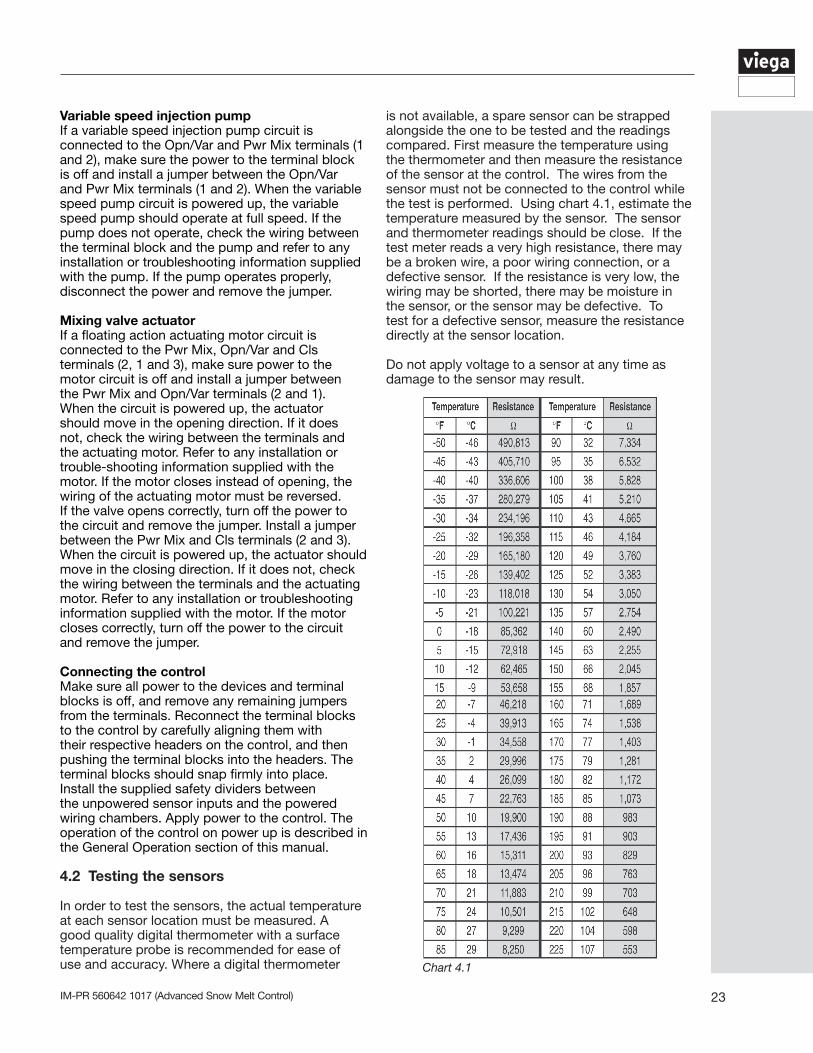
In order to test the sensors, the actual temperature at each sensor location must be measured. A good quality digital thermometer with a surface temperature probe is recommended for ease of use and accuracy. Where a digital thermometer Chart 4.1
is not available, a spare sensor can be strapped alongside the one to be tested and the readings compared. First measure the temperature using the thermometer and then measure the resistance of the sensor at the control. The wires from the sensor must not be connected to the control while the test is performed. Using chart 4.1, estimate the temperature measured by the sensor. The sensor and thermometer readings should be close. If the test meter reads a very high resistance, there may be a broken wire, a poor wiring connection, or a defective sensor. If the resistance is very low, the wiring may be shorted, there may be moisture in the sensor, or the sensor may be defective. To test for a defective sensor, measure the resistance directly at the sensor location.
Do not apply voltage to a sensor at any time as damage to the sensor may result.
IM-PR 560642 1017 (Advanced Snow Melt Control)24
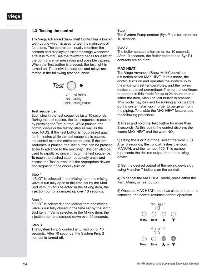
4.3 Testing the control The Viega Advanced Snow Melt Control has a built-in test routine which is used to test the main control functions. The control continually monitors the sensors and displays an error message whenever a fault is found. See the following pages for a list of the control’s error messages and possible causes. When the Test button is pressed, the test light is turned on. The individual outputs and relays are tested in the following test sequence.
Test sequence Each step in the test sequence lasts 10 seconds. During the test routine, the test sequence is paused by pressing the Test button. While paused, the control displays the testing step as well as the word PAUS. If the Test button is not pressed again for 5 minutes while the test sequence is paused, the control exits the entire test routine. If the test sequence is paused, the Test button can be pressed again to advance to the next step. This can also be used to rapidly advance through the test sequence. To reach the desired step, repeatedly press and release the Test button until the appropriate device and segment in the display turn on.
Step 1 If FLOT is selected in the Mixing item, the mixing valve is run fully open in the time set by the Motr Spd item. If Var is selected in the Mixing item, the injection pump is ramped up over 10 seconds.
Step 2If FLOT is selected in the Mixing item, the mixing valve is run fully closed in the time set by the Motr Spd item. If Var is selected in the Mixing item, the injection pump is ramped down over 10 seconds.
Step 3The System Pmp 2 contact is turned on for 10 seconds. After 10 seconds, the System Pmp 2 contact is turned off.
Step 4The System Pump contact (Sys P1) is turned on for 10 seconds.
Step 5The boiler contact is turned on for 10 seconds. After 10 seconds, the Boiler contact and Sys P1 contacts are shut off.
MAX HEATThe Viega Advanced Snow Melt Control has a function called MAX HEAT. In this mode, the control turns on and operates the system up to the maximum set temperatures, and the mixing device at the set percentage. The control continues to operate in this mode for up to 24 hours or until either the Item, Menu or Test button is pressed. This mode may be used for running all circulators during system start-up in order to purge air from the piping. To enable the MAX HEAT feature, use the following procedure.
1) Press and hold the Test button for more than 3 seconds. At this point, the control displays the words MAX HEAT and the word NO.
2) Using the or buttons, select the word YES. After 3 seconds, the control flashes the word MANUAL and the number 100. This number represents the desired output from the mixing device.
3) Set the desired output of the mixing device by using and/or buttons on the control.
4) To cancel the MAX HEAT mode, press either the Item, Menu, or Test button.
5) Once the MAX HEAT mode has either ended or is canceled, the control resumes normal operation.
Menu Item
Menu Item or
25IM-PR 560642 1017 (Advanced Snow Melt Control)
4.4 Error messages (1 of 2)
Error Displayed Description
The control was unable to store a piece of information into its EEPROM. This error can be caused by a noisy power source. The control will display the error message and will continue to operate as normal. Pressing either the Menu or Item button will clear this error.
The control was unable to read a piece of information stored in the ADJUST menu. Because of this, the control was required to load the factory settings into all of the items in the ADJUST menu. The control will stop operation until all of the items available in the ADJUST menu of the control have been checked by the user or installer.
An incorrect device has been connected to the tekmar Net™ tN2 input terminal. Once the problem has been corrected, press either the Menu or Item button to clear the error message from the control.
A short circuit has been read between the tN2 terminal and a Com terminal on the control. Either the wires leading to the tN2 device are shorted or the polarity of the wires is reversed. Determine the cause and remove the short. To clear this error, press either the Menu or Item button.
The control is no longer able to read the outdoor sensor due to a short circuit. In this case the control assumes an outdoor temperature of 32°F and continues operation. Locate the problem as described on page 22. To clear the error message from the control after the sensor has been repaired, press either the Menu or Item button.
The control is no longer able to read the outdoor sensor due to an open circuit. In this case the control assumes an outdoor temperature of 32°F and continues operation. Locate the problem as described on page 22. To clear the error message from the control after the sensor has been repaired, press either the Menu or Item button.
The control is no longer able to read the mixing supply sensor due to a short circuit. In this case, the control does not operate the snow melting system. Locate the problem as described on page 22. To clear the error message from the control after the sensor has been repaired, press either the Menu or Item button.
The control is no longer able to read the mixing supply sensor due to an open circuit. In this case, the control does not operate the snow melting system. Locate the problem as described on page 22. To clear the error message from the control after the sensor has been repaired, press either the Menu or Item button.
The control is no longer able to read the mixing return sensor due to a short circuit. If the ∆T MAX item is set to OFF, the control will continue to operate as if the as if the mixing return sensor was not connected to the control. If the ∆T MAX item is not set to OFF, the control does not operate the snow melting system. Locate the problem as described on page 22. To clear the error message from the control after the sensor has been repaired, press either the Menu or Item button.
The control is no longer able to read the mixing return sensor due to an open circuit. If the ∆T MAX item is set to OFF, the control will continue to operate as if the mixing return sensor was not connected to the control. If the ∆T MAX item is not set to OFF, the control does not operate the snow melting system. Locate the problem as described on page 22. To clear the error message from the control after the sensor has been repaired, press either the Menu or Item button.
The control is no longer able to read the boiler sensor due to a short circuit. If the Boil MIN item is set to OFF, the control operates the Boiler contact when the mixing device starts to operate. If the Boil MIN is not set to OFF, the control does not operate the snow melting system. Locate the problem as described on page 22. To clear the error message from the control after the sensor has been repaired, press either the Menu or Item button.
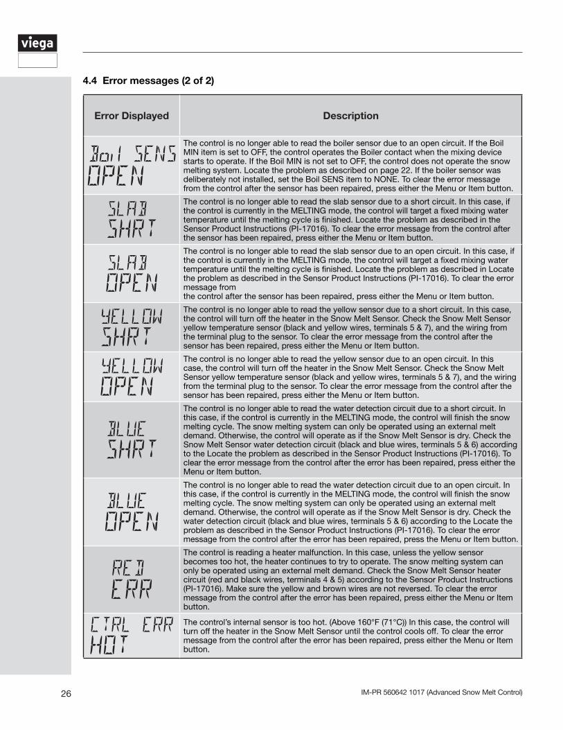
IM-PR 560642 1017 (Advanced Snow Melt Control)26
Error Displayed Description
The control is no longer able to read the boiler sensor due to an open circuit. If the Boil MIN item is set to OFF, the control operates the Boiler contact when the mixing device starts to operate. If the Boil MIN is not set to OFF, the control does not operate the snow melting system. Locate the problem as described on page 22. If the boiler sensor was deliberately not installed, set the Boil SENS item to NONE. To clear the error message from the control after the sensor has been repaired, press either the Menu or Item button.
The control is no longer able to read the slab sensor due to a short circuit. In this case, if the control is currently in the MELTING mode, the control will target a fixed mixing water temperature until the melting cycle is finished. Locate the problem as described in the Sensor Product Instructions (PI-17016). To clear the error message from the control after the sensor has been repaired, press either the Menu or Item button.
The control is no longer able to read the slab sensor due to an open circuit. In this case, if the control is currently in the MELTING mode, the control will target a fixed mixing water temperature until the melting cycle is finished. Locate the problem as described in Locate the problem as described in the Sensor Product Instructions (PI-17016). To clear the error message from the control after the sensor has been repaired, press either the Menu or Item button.
The control is no longer able to read the yellow sensor due to a short circuit. In this case, the control will turn off the heater in the Snow Melt Sensor. Check the Snow Melt Sensor yellow temperature sensor (black and yellow wires, terminals 5 & 7), and the wiring from the terminal plug to the sensor. To clear the error message from the control after the sensor has been repaired, press either the Menu or Item button.
The control is no longer able to read the yellow sensor due to an open circuit. In this case, the control will turn off the heater in the Snow Melt Sensor. Check the Snow Melt Sensor yellow temperature sensor (black and yellow wires, terminals 5 & 7), and the wiring from the terminal plug to the sensor. To clear the error message from the control after the sensor has been repaired, press either the Menu or Item button.
The control is no longer able to read the water detection circuit due to a short circuit. In this case, if the control is currently in the MELTING mode, the control will finish the snow melting cycle. The snow melting system can only be operated using an external melt demand. Otherwise, the control will operate as if the Snow Melt Sensor is dry. Check the Snow Melt Sensor water detection circuit (black and blue wires, terminals 5 & 6) according to the Locate the problem as described in the Sensor Product Instructions (PI-17016). To clear the error message from the control after the error has been repaired, press either the Menu or Item button.
The control is no longer able to read the water detection circuit due to an open circuit. In this case, if the control is currently in the MELTING mode, the control will finish the snow melting cycle. The snow melting system can only be operated using an external melt demand. Otherwise, the control will operate as if the Snow Melt Sensor is dry. Check the water detection circuit (black and blue wires, terminals 5 & 6) according to the Locate the problem as described in the Sensor Product Instructions (PI-17016). To clear the error message from the control after the error has been repaired, press the Menu or Item button.
The control is reading a heater malfunction. In this case, unless the yellow sensor becomes too hot, the heater continues to try to operate. The snow melting system can only be operated using an external melt demand. Check the Snow Melt Sensor heater circuit (red and black wires, terminals 4 & 5) according to the Sensor Product Instructions (PI-17016). Make sure the yellow and brown wires are not reversed. To clear the error message from the control after the error has been repaired, press either the Menu or Item button.
The control’s internal sensor is too hot. (Above 160°F (71°C)) In this case, the control will turn off the heater in the Snow Melt Sensor until the control cools off. To clear the error message from the control after the error has been repaired, press either the Menu or Item button.
4.4 Error messages (2 of 2)
27IM-PR 560642 1017 (Advanced Snow Melt Control)
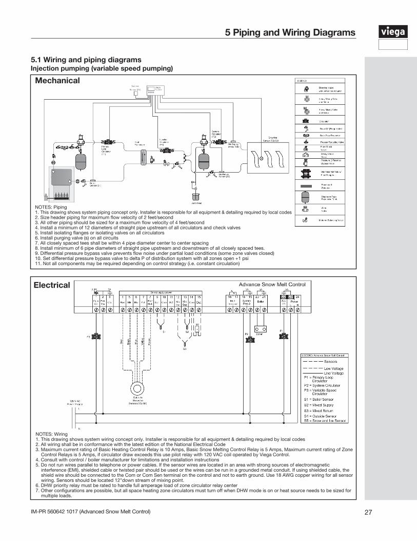
5.1 Wiring and piping diagrams Injection pumping (variable speed pumping)
NOTES: Piping1. This drawing shows system piping concept only. Installer is responsible for all equipment & detailing required by local codes2. Size header piping for maximum flow velocity of 2 feet/second3. All other piping should be sized for a maximum flow velocity of 4 feet/second4. Install a minimum of 12 diameters of straight pipe upstream of all circulators and check valves5. Install isolating flanges or isolating valves on all circulators6. Install purging valve (s) on all circuits7. All closely spaced tees shall be within 4 pipe diameter center to center spacing8. Install minimum of 6 pipe diameters of straight pipe upstream and downstream of all closely spaced tees.9. Differential pressure bypass valve prevents flow noise under partial load conditions (some zone valves closed)10. Set differential pressure bypass valve to delta P of distribution system with all zones open +1 psi11. Not all components may be required depending on control strategy (i.e. constant circulation)
Mechanical
NOTES: Wiring1. This drawing shows system wiring concept only. Installer is responsible for all equipment & detailing required by local codes2. All wiring shall be in conformance with the latest edition of the National Electrical Code3. Maximum current rating of Basic Heating Control Relay is 10 Amps, Basic Snow Melting Control Relay is 5 Amps, Maximum current rating of Zone
Control Relays is 5 Amps, if circulator draw exceeds this use pilot relay with 120 VAC coil operated by Viega Control.4. Consult with control / boiler manufacturer for limitations and installation instructions5. Do not run wires parallel to telephone or power cables. If the sensor wires are located in an area with strong sources of electromagnetic
interference (EMI), shielded cable or twisted pair should be used or the wires can be run in a grounded metal conduit. If using shielded cable, the shield wire should be connected to the Com or Com Sen terminal on the control and not to earth ground. Use 18 AWG copper wiring for all sensor wiring. Sensors should be located 12"down stream of mixing point.
6. DHW priority relay must be rated to handle full amperage load of zone circulator relay center7. Other configurations are possible, but all space heating zone circulators must turn off when DHW mode is on or heat source needs to be sized for
multiple loads.
Electrical
5 Piping and Wiring Diagrams
IM-PR 560642 1017 (Advanced Snow Melt Control)28
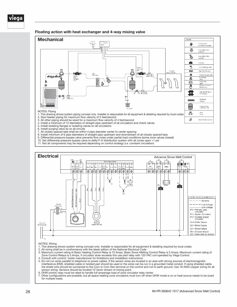
NOTES: Piping1. This drawing shows system piping concept only. Installer is responsible for all equipment & detailing required by local codes2. Size header piping for maximum flow velocity of 2 feet/second3. All other piping should be sized for a maximum flow velocity of 4 feet/second4. Install a minimum of 12 diameters of straight pipe upstream of all circulators and check valves5. Install isolating flanges or isolating valves on all circulators6. Install purging valve (s) on all circuits7. All closely spaced tees shall be within 4 pipe diameter center to center spacing8. Install minimum of 6 pipe diameters of straight pipe upstream and downstream of all closely spaced tees.9. Differential pressure bypass valve prevents flow noise under partial load conditions (some zone valves closed)10. Set differential pressure bypass valve to delta P of distribution system with all zones open +1 psi11. Not all components may be required depending on control strategy (i.e. constant circulation)
Mechanical
NOTES: Wiring1. This drawing shows system wiring concept only. Installer is responsible for all equipment & detailing required by local codes2. All wiring shall be in conformance with the latest edition of the National Electrical Code3. Maximum current rating of Basic Heating Control Relay is 10 Amps, Basic Snow Melting Control Relay is 5 Amps, Maximum current rating of
Zone Control Relays is 5 Amps, if circulator draw exceeds this use pilot relay with 120 VAC coil operated by Viega Control.4. Consult with control / boiler manufacturer for limitations and installation instructions5. Do not run wires parallel to telephone or power cables. If the sensor wires are located in an area with strong sources of electromagnetic
interference (EMI), shielded cable or twisted pair should be used or the wires can be run in a grounded metal conduit. If using shielded cable, the shield wire should be connected to the Com or Com Sen terminal on the control and not to earth ground. Use 18 AWG copper wiring for all sensor wiring. Sensors should be located 12"down stream of mixing point.
6. DHW priority relay must be rated to handle full amperage load of zone circulator relay center7. Other configurations are possible, but all space heating zone circulators must turn off when DHW mode is on or heat source needs to be sized
for multiple loads.
Electrical
Floating action with heat exchanger and 4-way mixing valve
29IM-PR 560642 1017 (Advanced Snow Melt Control)
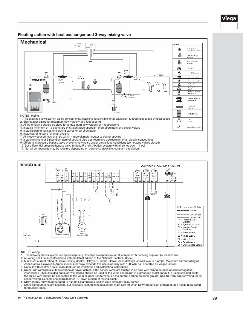
Floating action with heat exchanger and 3-way mixing valve
NOTES: Piping1. This drawing shows system piping concept only. Installer is responsible for all equipment & detailing required by local codes2. Size header piping for maximum flow velocity of 2 feet/second3. All other piping should be sized for a maximum flow velocity of 4 feet/second4. Install a minimum of 12 diameters of straight pipe upstream of all circulators and check valves5. Install isolating flanges or isolating valves on all circulators6. Install purging valve (s) on all circuits7. All closely spaced tees shall be within 4 pipe diameter center to center spacing8. Install minimum of 6 pipe diameters of straight pipe upstream and downstream of all closely spaced tees.9. Differential pressure bypass valve prevents flow noise under partial load conditions (some zone valves closed)10. Set differential pressure bypass valve to delta P of distribution system with all zones open +1 psi11. Not all components may be required depending on control strategy (i.e. constant circulation)
Mechanical
NOTES: Wiring1. This drawing shows system wiring concept only. Installer is responsible for all equipment & detailing required by local codes2. All wiring shall be in conformance with the latest edition of the National Electrical Code3. Maximum current rating of Basic Heating Control Relay is 10 Amps, Basic Snow Melting Control Relay is 5 Amps, Maximum current rating of
Zone Control Relays is 5 Amps, if circulator draw exceeds this use pilot relay with 120 VAC coil operated by Viega Control.4. Consult with control / boiler manufacturer for limitations and installation instructions5. Do not run wires parallel to telephone or power cables. If the sensor wires are located in an area with strong sources of electromagnetic
interference (EMI), shielded cable or twisted pair should be used or the wires can be run in a grounded metal conduit. If using shielded cable, the shield wire should be connected to the Com or Com Sen terminal on the control and not to earth ground. Use 18 AWG copper wiring for all sensor wiring. Sensors should be located 12"down stream of mixing point.
6. DHW priority relay must be rated to handle full amperage load of zone circulator relay center7. Other configurations are possible, but all space heating zone circulators must turn off when DHW mode is on or heat source needs to be sized
for multiple loads.
Electrical
IM-PR 560642 1017 (Advanced Snow Melt Control)30
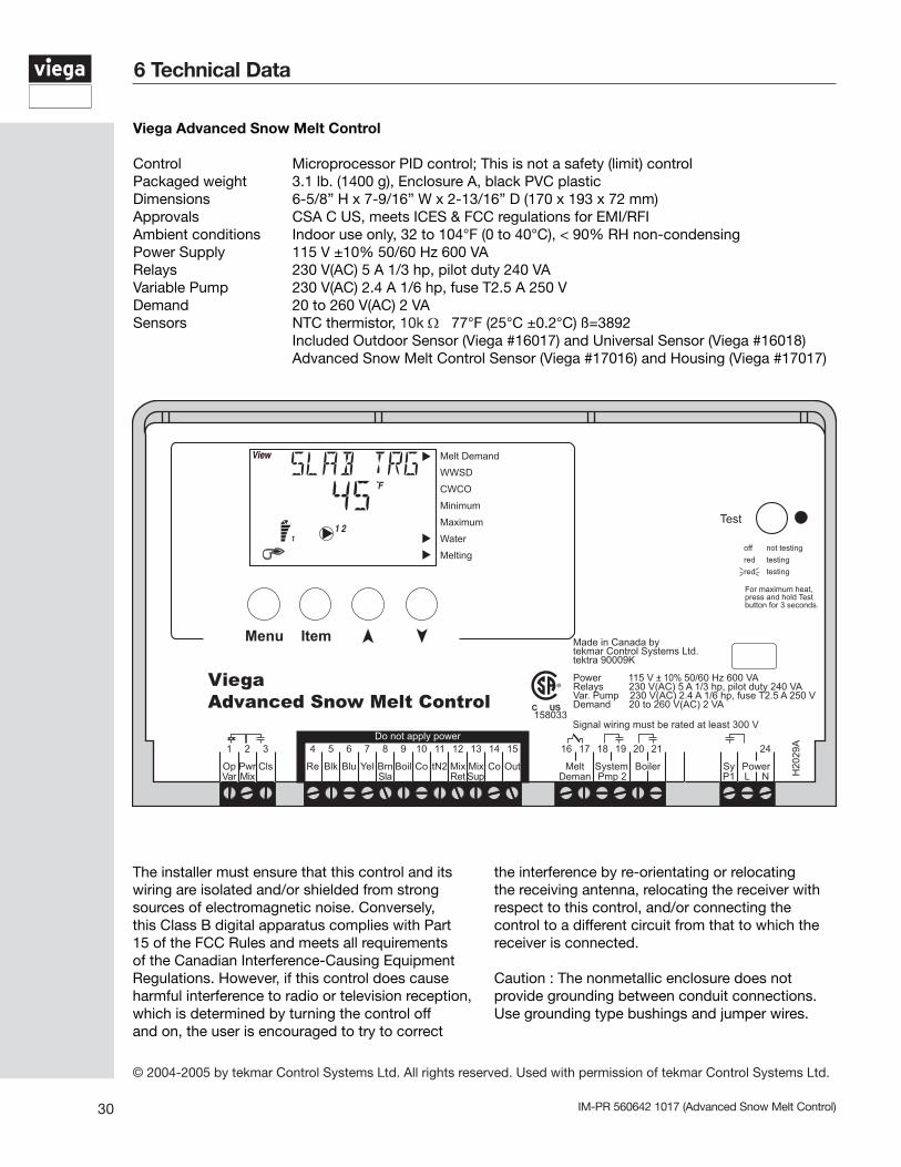
Viega Advanced Snow Melt Control
Control Microprocessor PID control; This is not a safety (limit) controlPackaged weight 3.1 lb. (1400 g), Enclosure A, black PVC plasticDimensions 6-5/8” H x 7-9/16” W x 2-13/16” D (170 x 193 x 72 mm)Approvals CSA C US, meets ICES & FCC regulations for EMI/RFIAmbient conditions Indoor use only, 32 to 104°F (0 to 40°C), < 90% RH non-condensingPower Supply 115 V ±10% 50/60 Hz 600 VARelays 230 V(AC) 5 A 1/3 hp, pilot duty 240 VAVariable Pump 230 V(AC) 2.4 A 1/6 hp, fuse T2.5 A 250 VDemand 20 to 260 V(AC) 2 VASensors NTC thermistor, 10k Ω 77°F (25°C ±0.2°C) ß=3892 Included Outdoor Sensor (Viega #16017) and Universal Sensor (Viega #16018) Advanced Snow Melt Control Sensor (Viega #17016) and Housing (Viega #17017)
6 Technical Data
© 2004-2005 by tekmar Control Systems Ltd. All rights reserved. Used with permission of tekmar Control Systems Ltd.
The installer must ensure that this control and its wiring are isolated and/or shielded from strong sources of electromagnetic noise. Conversely, this Class B digital apparatus complies with Part 15 of the FCC Rules and meets all requirements of the Canadian Interference-Causing Equipment Regulations. However, if this control does cause harmful interference to radio or television reception, which is determined by turning the control off and on, the user is encouraged to try to correct
the interference by re-orientating or relocating the receiving antenna, relocating the receiver with respect to this control, and/or connecting the control to a different circuit from that to which the receiver is connected.
Caution : The nonmetallic enclosure does not provide grounding between conduit connections. Use grounding type bushings and jumper wires.
31IM-PR 560642 1017 (Advanced Snow Melt Control)
Notes

IM-PR 560642 1017 (Advanced Snow Melt Control)
Viega LLC12303 Airport Way, Ste. 395 Broomfield, CO 80021 Phone: 1-800-976-9819 Fax: 1-800-976-9817 www.viega.us
This document subject to updates. For the most current Viega technical literature please visit www.viega.us.©2017, Viega®, ProPress®, MegaPress®, SeaPress®, PureFlow®, Smart Connect®, ManaBloc®, GeoFusion®, FostaPEX®, Radiant Wizard®, Climate Panel®, Climate Mat®, and Climate Track® are registered trademarks of Viega GmbH & Co. KG. SmartLoop® and Viega Eco Plus® are registered trademarks of Viega Holding GmbH & Co. Zero Lead™ and PolyAlloy™ are trademarks of Viega LLC. Eco Brass® is a registered trademark of Mitsubishi Shindoh Co., LTD. RIDGID® is a registered trademark of RIDGID, Inc. LoopCAD® is a registered trademark of Avenir Software Inc. Radel® is a registered trademark of Solvay Advanced Polymers, LLC.