Embed Size (px)
Citation preview

Order Number: MPC7400TS/DRev. 0, 8/1999
Semiconductor Products Sector
ª
Advance Information MPC7400 RISC Microprocessor Technical SummaryThis document provides an overview of the MPC7400 microprocessor features, including a block diagramshowing the major functional components. It provides information about how the MPC7400implementation complies with the PowerPCª architecture deÞnition.
AltiVec and the MPC7400
The MPC7400 is the Þrst processor to implement the AltiVec instruction set architecture. The portions ofthis document that describe the AltiVec technology are indicated by the icon in the margin. AltiVec featuresare described in the following sections:
¥ AltiVec registers are described in Table 3.
¥ AltiVec instructions are described in Section 1.5.2, ÒAltiVec Instruction Set.Ó
¥ Execution units for AltiVec instructions are described in Section 1.2.2.4.1, ÒAltiVec Vector Permute Unit (VPU),Ó and Section 1.2.2.4.2, ÒAltiVec Vector Arithmetic Logic Unit (VALU).Ó
1.1 MPC7400 Microprocessor OverviewThis section describes the features and general operation of the MPC7400 and provides a block diagramshowing major functional units. The MPC7400 is an implementation of the PowerPC microprocessor familyof reduced instruction set computer (RISC) microprocessors. The MPC7400 implements the 32-bit portionof the PowerPC architecture, which provides 32-bit effective addresses, integer data types of 8, 16, and 32bits, and ßoating-point data types of 32 and 64 bits.
The MPC7400 also implements the AltiVec instruction set architectural extension of the PowerPCarchitecture. The MPC7400 is a superscalar processor that can dispatch and complete two instructionssimultaneously. It incorporates the following execution units:
PRELIMINARYÑSUBJECT TO CHANGE WITHOUT NOTICE
This document contains information on a new product under development byMotorola. Motorola reserves the right to change or discontinue this product without
© Motorola, Inc., 1999. All rights reserved.

MPC7400 Microprocessor Overview
¥ Floating-point unit (FPU)
¥ Branch processing unit (BPU)
¥ System register unit (SRU)
¥ Load/store unit (LSU)
¥ Two integer units (IUs): IU1 executes all integer instructions. IU2 executes all integer instructions except multiply and divide instructions.
¥ Two vector units that support AltiVec instructions:
Ñ Vector permute unit (VPU)
Ñ Vector arithmetic logic unit (VALU), which consists of the following independent subunits:
Ð Vector simple integer unit (VSIU)
Ð Vector complex integer unit (VCIU)
Ð Vector ßoating-point unit (VFPU)
The ability to execute several instructions in parallel and the use of simple instructions with rapid executiontimes yield high efÞciency and throughput for MPC7400-based systems. Most integer instructions(including VSIU instructions) have a one-clock cycle execution latency.
The FPU and VFPU are pipelined, the tasks they perform are broken into subtasks executed in successivestages. Typically, a ßoating-point instruction occupies only one of the three FPU stages at a time, freeingthe previous stage to work on the next ßoating-point instruction. Thus, three ßoating-point instructions canbe in the FPU execute stage at a time and one ßoating-point instruction can Þnish executing per processorclock cycle.
The VFPU has four pipeline stages when executing in non-Java mode and Þve when executing in Java mode.
Note that for the MPC7400, double- and single-precision versions of ßoating-point instructions have thesame latency. For example, a ßoating-point multiply-add instruction takes three cycles to execute, regardlessof whether it is single- (fmadds) or double-precision (fmadd).
Figure 1 shows the parallel organization of the execution units (shaded in the diagram). The instruction unitfetches, dispatches, and predicts branch instructions. Note that this is a conceptual model that shows basicfeatures rather than attempting to show how features are implemented physically.
The MPC7400 has independent on-chip, 32-Kbyte, eight-way set-associative, physically addressed cachesfor instructions and data and independent instruction and data memory management units (MMUs). EachMMU has a 128-entry, two-way set-associative translation lookaside buffer (DTLB and ITLB) that savesrecently used page address translations. Block address translation is done through the four-entry instructionand data block address translation (IBAT and DBAT) arrays, deÞned by the PowerPC architecture. Duringblock translation, effective addresses are compared simultaneously with all four BAT entries.
The L2 cache is implemented with an on-chip, two-way, set-associative tag memory, and with external,synchronous SRAMs for data storage. The external SRAMs are accessed through a dedicated L2 cache portthat supports a single bank of 0.5, 1, or 2 Mbyte of synchronous SRAMs.
The MPC7400 has four software-controllable power-saving modes. Three static modes, doze, nap, andsleep, progressively reduce power dissipation. When functional units are idle, a dynamic powermanagement mode causes those units to enter a low-power mode automatically without affectingoperational performance, software execution, or external hardware.
The MPC7400 uses an advanced CMOS process technology and is fully compatible with TTL devices.
2 MPC7400 RISC Microprocessor Technical Summary PRELIMINARYÑSUBJECT TO CHANGE WITHOUT NOTICE

MP
C7400 R
ISC
Micro
pro
cessor Tech
nical S
um
mary
3
PR
EL
IMIN
AR
YÑ
SU
BJE
CT
TO C
HA
NG
E W
ITH
OU
T N
OT
ICE
MP
C7400 M
icrop
rocesso
r Overview
FPSCRFPSCR
+ x Ö
Reservation
128-Bit(4 Instructions)
Floating-Point Unit
64-Bit
Reservation
oad/Store Unit (EA Calculation)
ished
Tags 32-KbyteD Cache
Memory Subsystem
Instruction
Data Reload
StationFPR File
6 Rename Buffers
tation (2 Entry)
64-Bit
Reload Table
pleted
Instruction MMU
SRs(Shadow)
128-EntryIBATArray
ITLB
Table
Tags 32-Kbytei Cache
Data ReloadQueue
InstructionReload Queue
Transaction
Data MMU
SRs(Original)
128-EntryDBATArray
DTLB
Queue
Load Fold
L1
tores
tores
Operations
Fig
ure 1. M
PC
7400 Micro
pro
cessor B
lock D
iagram
Additional Features• Time Base Counter/Decrementer• Clock Multiplier• JTAG/COP Interface• Thermal/Power Management
+
+
Fetcher Branch Processing
BTIC(64 Entry)
+ x Ö
VSCR
L2CR
CTRLR
PA
EA
Instruction Unit
Unit
Instruction Queue(6 Word)
2 Instructions
Integer System
Dispatch Unit
64-Bit (2 Instructions)
32-Bit
32-Bit
L
Fin
32-Bit
Completion Unit
Completion Queue(8 Entry)
L2 ControllerL2 Tags
Bus Interface Unit
L2 Castout
32-Bit 60x/MAX Address Bus64-Bit 60x Data Bus/128-Bit MAX Data Bus
19-Bit L2 Address Bus64-/128-Bit L2 Data Bus
Integer
Reservation Station
Reservation Station
Register UnitUnit 1 Unit 2
Reservation Station
SGPR File
6 Rename Buffers
VCIU
Vector Vector ALU
Reservation Station
Reservation Station
Permute
VR File
6 Rename Buffers
Unit VSIU VFPU
128-Bit128-Bit
Ability to complete up
Com
BHT(512 Entry)
L2 Miss DataTransaction
to two instructions per clock
S
S
L2 DataTransaction
VectorTouchQueue

MPC7400 Microprocessor Features
1.2 MPC7400 Microprocessor FeaturesThis section lists features of the MPC7400. The interrelationships of these features are shown Figure 1.
1.2.1 Overview of the MPC7400 Microprocessor FeaturesMajor features of the MPC7400 are as follows:
¥ High-performance, superscalar microprocessor
Ñ As many as four instructions can be fetched from the instruction cache per clock cycle
Ñ As many as two instructions can be dispatched per clock
Ñ As many as eight instructions can execute per clock (including two integer instructions and four AltiVec instructions)
Ñ Single-clock-cycle execution for most instructions
Ñ One instruction per clock throughput for most instructions
¥ Eight independent execution units and three register Þles
Ñ BPU featuring both static and dynamic branch prediction
Ð 64-entry (16-set, four-way set-associative) branch target instruction cache (BTIC), a cache of branch instructions that have been encountered in branch/loop code sequences. If a target instruction is in the BTIC, it is fetched into the instruction queue a cycle sooner than it can be made available from the instruction cache. Typically, if a fetch access hits the BTIC, it provides the Þrst two instructions in the target stream.
Ð 512-entry branch history table (BHT) with two bits per entry for four levels of predictionÑnot-taken, strongly not-taken, taken, strongly taken
Ð Branch instructions that do not update the count register (CTR) or link register (LR) are removed from the instruction stream.
Ñ Two integer units (IUs) that share 32 GPRs for integer operands
Ð IU1 can execute any integer instruction.
Ð IU2 can execute all integer instructions except multiply and divide instructions (shift, rotate, arithmetic, and logical instructions). Most instructions that execute in the IU2 take one cycle to execute. The IU2 has a single-entry reservation station.
Ñ Three-stage FPU and a 32-entry FPR Þle
Ð Fully IEEE 754-1985-compliant FPU for both single- and double-precision operations
Ð Supports non-IEEE mode for time-critical operations
Ð Hardware support for denormalized numbers
Ð Single-entry reservation station
Ð Thirty-two 64-bit FPRs for single- or double-precision operands
Ñ Two vector units and 32-entry vector register Þle (VRs)
Ð Vector permute unit (VPU)
Ð Vector arithmetic logic unit (VALU), which consists of the three independent subunits: vector simple integer unit (VSIU), vector complex integer unit (VCIU), and vector ßoating-point unit (VFPU)
Ñ Two-stage LSU
Ð Supports integer, ßoating-point and vector instruction load/store trafÞc
Ð Four-entry vector touch queue (VTQ) supports all four architected AltiVec data stream operations
4 MPC7400 RISC Microprocessor Technical Summary PRELIMINARYÑSUBJECT TO CHANGE WITHOUT NOTICE

MPC7400 Microprocessor Features
Ð Two-entry reservation station
Ð Single-cycle, pipelined load or store cache accesses (byte, half, word, doubleword)
Ð (including unaligned accesses within a doubleword boundary)
Ð Dedicated adder calculates effective addresses (EAs)
Ð Supports store gathering
Ð Performs alignment, normalization, and precision conversion for ßoating-point data
Ð Executes cache control and TLB instructions
Ð Performs alignment, zero padding, and sign extension for integer data
Ð Hits under misses (multiple outstanding misses)
Ð Six-entry store queue
Ð Sequencing for load/store multiples and string operations
Ð Supports both big- and little-endian modes, including misaligned Little-endian accesses
Ñ SRU handles miscellaneous instructions
Ð Executes CR logical and Move to/Move from SPR instructions (mtspr and mfspr)
Ð Single-entry reservation station
¥ Rename buffers
Ñ Six GPR rename buffers
Ñ Six FPR rename buffers
Ñ Six VR rename buffers
Ñ Condition register buffering supports two CR writes per clock
¥ Completion unit
Ñ The completion unit retires an instruction from the eight-entry reorder buffer (completion queue) when all instructions ahead of it have been completed, the instruction has Þnished execution, and no exceptions are pending.
Ñ Guarantees sequential programming model (precise exception model)
Ñ Monitors all dispatched instructions and retires them in order
Ñ Tracks unresolved branches and ßushes instructions from the mispredicted branch
Ñ Retires as many as two instructions per clock
¥ Separate on-chip instruction and data caches (Harvard architecture)
Ñ 32-Kbyte, eight-way set-associative instruction and data caches
Ñ Pseudo least-recently-used (PLRU) replacement algorithm
Ñ 32-byte (eight-word) L1 cache block
Ñ Physically indexed/physical tags. (Note that the PowerPC architecture refers to physical address space as real address space.)
Ñ Cache write-back or write-through operation programmable on a per-page or per-block basis
Ñ Instruction cache can provide four instructions per clock; data cache can provide four words per clock
Ñ Caches can be disabled in software
Ñ Caches can be locked in software
Ñ Data cache coherency (MEI, MESI, and MERSI) maintained in hardware
Ñ Separate copy of data cache tags for efÞcient snooping
MPC7400 RISC Microprocessor Technical Summary 5PRELIMINARYÑSUBJECT TO CHANGE WITHOUT NOTICE

MPC7400 Microprocessor Features
Ñ No snooping of instruction cache except for icbi instruction
Ñ Data cache supports AltiVec LRU and transient instructions, as described in Section 1.5.2, ÒAltiVec Instruction Set.Ó
Ñ The critical double word is made available to the requesting unit when it is burst into the reload data queue. The caches are nonblocking, so they can be accessed during this operation.
¥ Level 2 (L2) cache interface
Ñ L2 is fully pipelined to provide 64 bits per L2 clock cycle to the L1 caches
Ñ On-chip two-way set-associative L2 cache controller and tags
Ñ External data SRAMs
Ñ Support for 512-Kbyte, 1-Mbyte, and 2-Mbyte L2 caches
Ñ Copyback or write-through data cache (on a page basis, or for all L2)
Ñ 32-byte (512 K), 64-byte (1 M), or 128-byte (2 M) sectored line size
Ñ Supports pipelined (register-register) synchronous burst SRAMs and pipelined (register-register) late-write synchronous burst SRAMs
Ñ Core-to-L2 frequency divisors of ¸1, ¸1.5, ¸2, ¸2.5, ¸3, ¸3.5, and ¸4 supported
Ñ 64-bit data bus
¥ Separate memory management units (MMUs) for instructions and data
Ñ 52-bit virtual address; 32-bit physical address
Ñ Address translation for 4-Kbyte pages, variable-sized blocks, and 256-Mbyte segments
Ñ Memory programmable as write-back/write-through, cacheable/noncacheable, and coherency enforced/coherency not enforced on a page or block basis
Ñ Separate IBATs and DBATs (four each) also deÞned as SPRs
Ñ Separate instruction and data translation lookaside buffers (TLBs)
Ð Both TLBs are 128-entry, two-way set associative, and use LRU replacement algorithm
Ð TLBs are hardware-reloadable (that is, the page table search is performed in hardware)
¥ EfÞcient data ßow
Ñ All data buses between VRs, LSU, L1s, L2, and the bus are 64 bits wide
Ñ The data L1 is fully pipelined to provide 128 bits/cycle to/from the VRs
Ñ L2 is fully pipelined to provide 64 bits per L2 clock cycle to the L1s
Ñ Up to 8 outstanding, out-of-order, cache misses allowed between the data L1 and L2/bus
Ñ Up to seven outstanding, out-of-order transactions on the bus
Ñ Load folding to fold new data L1 misses into older, outstanding load and store misses to the same line
Ñ Store miss merging for multiple store misses to the same line. Only coherency action taken (address-only) for store misses merged to all 32 bytes of a cache block (no data tenure needed).
Ñ Two-entry Þnished store queue and 4-entry completed store queue between the LSU and the data L1
Ñ Separate additional queues for efÞcient buffering of outbound data (such as cast outs and write throughs) from the data L1 and L2
¥ Multiprocessing support features include the following:
Ñ Hardware-enforced, cache coherency protocols for data cache.
Ð Three-state (MEI) similar to the MPC750
6 MPC7400 RISC Microprocessor Technical Summary PRELIMINARYÑSUBJECT TO CHANGE WITHOUT NOTICE

MPC7400 Microprocessor Features
Ð Four-state (MESI) similar to the MPC604
Ð Five-state (MERSI), where the new R state allows shared intervention
Ñ Load/store with reservation instruction pair for atomic memory references, semaphores, and other multiprocessor operations
¥ Power and thermal management
Ñ Three static modes, doze, nap, and sleep, progressively reduce power dissipation:
Ð DozeÑAll the functional units are disabled except for the time base/decrementer registers and the bus snooping logic.
Ð NapÑThe nap mode further reduces power consumption by disabling bus snooping, leaving only the time base register and the PLL in a powered state.
Ð SleepÑAll internal functional units are disabled, after which external system logic may disable the PLL and SYSCLK.
Ñ Thermal management facility provides software-controllable thermal management. Thermal management is performed through the use of three supervisor-level registers and an MPC7400-speciÞc thermal management exception.
Ñ Instruction cache throttling provides control of instruction fetching to limit power consumption.
¥ Performance monitor can be used to help debug system designs and improve software efÞciency.
¥ In-system testability and debugging features through JTAG boundary-scan capability
1.2.2 Instruction FlowAs shown in Figure 1, the MPC7400 instruction unit provides centralized control of instruction ßow to theexecution units. The instruction unit contains a sequential fetcher, six-entry instruction queue (IQ), dispatchunit, and BPU. It determines the address of the next instruction to be fetched based on information from thesequential fetcher and from the BPU.
The sequential fetcher loads instructions from the instruction cache into the instruction queue. The BPUextracts branch instructions from the sequential fetcher. Branch instructions that cannot be resolvedimmediately are predicted using either the MPC7400-speciÞc dynamic branch prediction or thearchitecture-deÞned static branch prediction.
Branch instructions that do not affect the LR or CTR are removed from the instruction stream. The BPUfolds branch instructions when a branch is taken (or predicted as taken); branch instructions that are nottaken, or predicted as not taken, are removed from the instruction stream through the dispatch mechanism.
Instructions issued beyond a predicted branch do not complete execution until the branch is resolved,preserving the programming model of sequential execution. If branch prediction is incorrect, the instructionunit ßushes all predicted path instructions, and instructions are fetched from the correct path.
1.2.2.1 Instruction Queue and Dispatch UnitThe instruction queue (IQ), shown in Figure 1, holds as many as six instructions and loads up to fourinstructions from the instruction cache during a single processor clock cycle. The instruction fetchercontinuously attempts to load as many instructions as there were vacancies in the IQ in the previous clockcycle. All instructions except branch, Return from Interrupt (rÞ), System Call (sc), and InstructionSynchronize (isync) instructions are dispatched to their respective execution units from the bottom twopositions in the instruction queue (IQ0 and IQ1) at a maximum rate of two instructions per cycle.Reservation stations are provided for the IU1, IU2, FPU, LSU, SRU, VPU, and VALU. The dispatch unitchecks for source and destination register dependencies, determines whether a position is available in thecompletion queue, and inhibits subsequent instruction dispatching as required.
MPC7400 RISC Microprocessor Technical Summary 7PRELIMINARYÑSUBJECT TO CHANGE WITHOUT NOTICE
MPC7400 Microprocessor Features
Branch instructions can be detected, decoded, and predicted from anywhere in the instruction queue.
1.2.2.2 Branch Processing Unit (BPU)The BPU receives branch instructions from the sequential fetcher and performs CR lookahead operationson conditional branches to resolve them early, achieving the effect of a zero-cycle branch in many cases.
Unconditional branch instructions and conditional branch instructions in which the condition is known canbe resolved immediately. For unresolved conditional branch instructions, the branch path is predicted usingeither the architecture-deÞned static branch prediction or the MPC7400-speciÞc dynamic branch prediction.Dynamic branch prediction is enabled if HID0[BHT] = 1.
When a prediction is made, instruction fetching, dispatching, and execution continue from the predictedpath, but instructions cannot complete and write back results to architected registers until the prediction isdetermined to be correct (resolved). When a prediction is incorrect, the instructions from the incorrect pathare ßushed from the processor and processing begins from the correct path. The MPC7400 allows a secondbranch instruction to be predicted; instructions from the second predicted instruction stream can be fetchedbut cannot be dispatched.
Dynamic prediction is implemented using a 512-entry branch history table (BHT), a cache that provides twobits per entry that together indicate four levels of prediction for a branch instructionÑnot-taken, stronglynot-taken, taken, strongly taken. When dynamic branch prediction is disabled, the BPU uses a bit in theinstruction encoding to predict the direction of the conditional branch. Therefore, when an unresolvedconditional branch instruction is encountered, the MPC7400 executes instructions from the predicted targetstream although the results are not committed to architected registers until the conditional branch isresolved. This execution can continue until a second unresolved branch instruction is encountered.
When a branch is taken (or predicted as taken), the instructions from the untaken path must be ßushed andthe target instruction stream must be fetched into the IQ. The BTIC is a 64-entry, four-way set associativecache that contains the most recently used branch target instructions, typically in pairs. When an instructionfetch hits in the BTIC, the instructions arrive in the instruction queue in the next clock cycle, a clock cyclesooner than they would arrive from the instruction cache. Additional instructions arrive from the instructioncache in the next clock cycle. The BTIC reduces the number of missed opportunities to dispatch instructionsand gives the processor a one-cycle head start on processing the target stream.
The BPU contains an adder to compute branch target addresses and three user-control registersÑthe linkregister (LR), the count register (CTR), and the CR. The BPU calculates the return pointer for subroutinecalls and saves it into the LR for certain types of branch instructions. The LR also contains the branch targetaddress for the Branch Conditional to Link Register (bclrx) instruction. The CTR contains the branch targetaddress for the Branch Conditional to Count Register (bcctrx) instruction. Because the LR and CTR areSPRs, their contents can be copied to or from any GPR. Because the BPU uses dedicated registers ratherthan GPRs or FPRs, execution of branch instructions is largely independent from execution of integer andßoating-point instructions.
1.2.2.3 Completion UnitThe completion unit operates closely with the instruction unit. Instructions are fetched and dispatched inprogram order. At the point of dispatch, the program order is maintained by assigning each dispatchedinstruction a successive entry in the eight-entry completion queue. The completion unit tracks instructionsfrom dispatch through execution and retires them in program order from the two bottom entries in thecompletion queue (CQ0 and CQ1).
Instructions cannot be dispatched to an execution unit unless there is a vacancy in the completion queue.Branch instructions that do not update the CTR or LR are removed from the instruction stream and do nottake an entry in the completion queue. Instructions that update the CTR and LR follow the same dispatchand completion procedures as non-branch instructions, except that they are not issued to an execution unit.
8 MPC7400 RISC Microprocessor Technical Summary PRELIMINARYÑSUBJECT TO CHANGE WITHOUT NOTICE

MPC7400 Microprocessor Features
Completing an instruction commits execution results to architected registers (GPRs, FPRs, VRs, LR, andCTR). In-order completion ensures the correct architectural state when the MPC7400 must recover from amispredicted branch or any exception. Retiring an instruction removes it from the completion queue.
1.2.2.4 Independent Execution UnitsIn addition to the BPU, the MPC7400 provides the seven execution units described in the following sections.
1.2.2.4.1 AltiVec Vector Permute Unit (VPU)The VPU performs the following permutations on vector operands. These instructions are described in detailin Chapter 2, ÒAddressing Modes and Instruction Set Summary,Ó in the AltiVec Technology ProgrammingEnvironments Manual.
¥ PackÑVector pack instructions truncate the contents of two concatenated source operands (grouped as eight words or sixteen half words) into a single result of eight half words or sixteen bytes, respectively.
¥ UnpackÑVector unpack instructions unpack the 8 low or high bytes (or 4 low or high half words) of one source operand into 8 half words (or 4 words) using sign extension to Þll the MSBs.
¥ MergeÑByte vector merge instructions interleave the 8 low bytes (or 8 high bytes) from two source operands producing a result of 16 bytes. Similarly, half-word vector merge instructions interleave the 4 low half words (or 4 high half words) of two source operands producing a result of 8 half words, and word vector merge instructions interleave the 2 low words (or 2 high words) from two source operands producing a result of 4 words. The vector merge instruction has many uses, notable among them is a way to efÞciently transpose SIMD vectors.
¥ SplatÑVector splat instructions prepare vector data for performing operations for which one source vector is to consist of elements that all have the same value (for example, multiplying all elements of a vector register by a constant). Vector splat instructions also can move data. For example to multiply all elements of a vector register by a constant, the vector splat instructions can be used to splat the scalar into a vector register. Likewise, when storing a scalar into an arbitrary memory location, it must be splatted into a vector register, and that register speciÞed as the source of the store. This guarantees that the data appears in all possible positions of that scalar size for the store.
¥ PermuteÑPermute instructions allow any byte in any two source vector registers to be directed to any byte in the destination vector. The Þelds in a third source operand specify from which Þeld in the source operands the corresponding destination Þeld is to be taken. The Vector Permute (vperm) instruction is a very powerful one that provides many useful functions. For example, it can be used efÞciently to perform table lookups and data alignment.
¥ SelectÑData ßow in the vector unit can be controlled without branching by using a vector compare and the vector select (vsel) instructions. In this use, the compare result vector is used directly as a mask operand to vector select instructions.The vsel instruction selects one Þeld from one or the other of two source operands under control of its mask operand. Use of the TRUE/FALSE compare result vector with select in this manner produces a two instruction equivalent of conditional execution on a per-Þeld basis.
1.2.2.4.2 AltiVec Vector Arithmetic Logic Unit (VALU)As shown in Figure 1, the VALU consists of the following three independent subunits:
¥ Vector simple integer unit (VSIU)Ñexecutes simple vector integer computational instructions, such as addition, subtraction, maximum and minimum comparisons, averaging, rotation, shifting, comparisons, and Boolean operations
¥ Vector complex integer unit (VCIU)Ñexecutes longer-latency vector integer instructions, such as multiplication, division, multiplication/addition, and sum-across with saturation
¥ Vector ßoating-point unit (VFPU)Ñexecutes all vector ßoating-point instructions
MPC7400 RISC Microprocessor Technical Summary 9PRELIMINARYÑSUBJECT TO CHANGE WITHOUT NOTICE

MPC7400 Microprocessor Features
Although only one instruction can be dispatched to the VALU per processor clock cycle, all three subunitscan execute simultaneously. For example, if instructions are dispatched one at a time to the VFPU, VCIU,and VSIU, all three subunits can be executing separate instructions, and, if enough VR rename resources areavailable, two of them can write back their results in the same clock cycle.
1.2.2.4.3 Integer Units (IUs)The integer units IU1 and IU2 are shown in Figure 1. The IU1 can execute any integer instruction; the IU2can execute any integer instruction except multiplication and division instructions. Each IU has a single-entry reservation station that can receive instructions from the dispatch unit and operands from the GPRs orthe rename buffers.
Each IU consists of three single-cycle subunitsÑa fast adder/comparator, a subunit for logical operations,and a subunit for performing rotates, shifts, and count-leading-zero operations. These subunits handle allone-cycle arithmetic instructions; only one subunit can execute an instruction at a time.
The IU1 has a 32-bit integer multiplier/divider as well as the adder, shift, and logical units of the IU2. Themultiplier supports early exit for operations that do not require full 32- x 32-bit multiplication.
Each IU has a dedicated result bus (not shown in Figure 1) that connects to rename buffers.
1.2.2.4.4 Floating-Point Unit (FPU)The FPU, shown in Figure 1., is designed such that single-precision operations require only a single pass,with a latency of three cycles. As instructions are dispatched to the FPUÕs reservation station, source operanddata can be accessed from the FPRs or from the FPR rename buffers. Results in turn are written to therename buffers and are made available to subsequent instructions. Instructions pass through the reservationstation in dispatch order.
The FPU contains a single-precision multiply-add array and the ßoating-point status and control register(FPSCR). The multiply-add array allows the MPC7400 to efÞciently implement multiply and multiply-addoperations. The FPU is pipelined so that one single- or double-precision instruction can be issued per clockcycle. Thirty-two 64-bit ßoating-point registers are provided to support ßoating-point operations. Stalls dueto contention for FPRs are minimized by automatic allocation of the six ßoating-point rename registers. TheMPC7400 writes the contents of the rename registers to the appropriate FPR when ßoating-pointinstructions are retired by the completion unit.
The MPC7400 supports all IEEE 754 ßoating-point data types (normalized, denormalized, NaN, zero, andinÞnity) in hardware, eliminating the latency incurred by software exception routines. (Note that exceptionis also referred to as interrupt in the architecture speciÞcation.)
1.2.2.4.5 Load/Store Unit (LSU)The LSU executes all load and store instructions as well as the AltiVec LRU and transient instructions andprovides the data transfer interface between the GPRs, FPRs, VRs, and the cache/memory subsystem. TheLSU calculates effective addresses, performs data alignment, and provides sequencing for load/store stringand multiple instructions.
Load and store instructions are issued and translated in program order; however, some memory accesses canoccur out of order. Synchronizing instructions can be used to enforce strict ordering. When there are no datadependencies and the guarded bit for the page or block is cleared, a maximum of one out-of-order cacheableload operation can execute per cycle, with a two-cycle total latency on a cache hit. Data returned from thecache is held in a rename register until the completion logic commits the value to a GPR, FPR, or VR. Storescannot be executed out of order and are held in the store queue until the completion logic signals that thestore operation is to be completed to memory. The MPC7400 executes store instructions with a maximumthroughput of one per cycle and a three-cycle total latency to the data cache. The time required to performthe actual load or store operation depends on the processor/bus clock ratio and whether the operationinvolves the on-chip cache, the L2 cache, system memory, or an I/O device.
10 MPC7400 RISC Microprocessor Technical Summary PRELIMINARYÑSUBJECT TO CHANGE WITHOUT NOTICE

MPC7400 Microprocessor Features
1.2.2.4.6 System Register Unit (SRU)The SRU executes various system-level instructions, as well as condition register logical operations andmove to/from special-purpose register instructions. To maintain system state, most instructions executed bythe SRU are execution-serialized; that is, the instruction is held for execution in the SRU until all previouslyissued instructions have executed. Results from execution-serialized instructions executed by the SRU arenot available or forwarded for subsequent instructions until the instruction completes.
1.2.3 Memory Management Units (MMUs)The MPC7400Õs MMUs support up to 4 Petabytes (252) of virtual memory and 4 Gigabytes (232) of physicalmemory for instructions and data. The MMUs also control access privileges for these spaces on block andpage granularities. Referenced and changed status is maintained by the processor for each page to supportdemand-paged virtual memory systems.
The LSU calculates effective addresses for data loads and stores; the instruction unit calculates effectiveaddresses for instruction fetching. The MMU translates the effective address to determine the correctphysical address for the memory access.
The MPC7400 supports the following types of memory translation:
¥ Real addressing modeÑIn this mode, translation is disabled by clearing bits in the machine state register (MSR): MSR[IR] for instruction fetching or MSR[DR] for data accesses. When address translation is disabled, the physical address is identical to the effective address.
¥ Page address translationÑtranslates the page frame address for a 4-Kbyte page size
¥ Block address translationÑtranslates the base address for blocks (128 Kbytes to 256 Mbytes)
If translation is enabled, the appropriate MMU translates the higher-order bits of the effective address intophysical address bits. The lower-order address bits (that are untranslated and therefore, considered bothlogical and physical) are directed to the on-chip caches where they form the index into the eight-way set-associative tag array. After translating the address, the MMU passes the higher-order physical address bitsto the cache and the cache lookup completes. For caching-inhibited accesses or accesses that miss in thecache, the untranslated lower-order address bits are concatenated with the translated higher-order addressbits; the resulting 32-bit physical address is used by the memory unit and the system interface, whichaccesses external memory.
The TLBs store page address translations for recent memory accesses. For each access, an effective addressis presented for page and block translation simultaneously. If a translation is found in both the TLB and theBAT array, the block address translation in the BAT array is used. Usually the translation is in a TLB andthe physical address is readily available to the on-chip cache. When a page address translation is not in aTLB, hardware searches for one in the page table following the model deÞned by the PowerPC architecture.
Instruction and data TLBs provide address translation in parallel with the on-chip cache access, incurringno additional time penalty in the event of a TLB hit. The MPC7400Õs TLBs are 128-entry, two-way set-associative caches that contain instruction and data address translations. The MPC7400 automaticallygenerates a TLB search on a TLB miss.
1.2.4 On-Chip Instruction and Data CachesThe MPC7400 implements separate instruction and data caches. Each cache is 32-Kbyte and eight-way setassociative. As deÞned by the PowerPC architecture, they are physically indexed. Each cache block containseight contiguous words from memory that are loaded from an 8-word boundary (that is, bits EA[27Ð31] arezeros); thus, a cache block never crosses a page boundary. An entire cache block can be updated by a four-beat burst load from a 64-bit system bus. Misaligned accesses across a page boundary can incur aperformance penalty. Caches are nonblocking, write-back caches with hardware support for reloading on
MPC7400 RISC Microprocessor Technical Summary 11PRELIMINARYÑSUBJECT TO CHANGE WITHOUT NOTICE

MPC7400 Microprocessor Features
cache misses. The critical double word is transferred on the Þrst beat and is simultaneously written to thecache and forwarded to the requesting unit, minimizing stalls due to load delays. The cache being loaded isnot blocked to internal accesses while the load completes.
The MPC7400 cache organization is shown in Figure 2.
Figure 2. L1 Cache Organization
Within one cycle, the data cache provides quad-word access to the LSU. Like the instruction cache, the datacache can be invalidated all at once or on a per-cache-block basis. The data cache can be disabled andinvalidated by clearing HID0[DCE] and setting HID0[DCFI]. The data cache can be locked by settingHID0[DLOCK]. The data cache tags are dual-ported, so a load or store can occur simultaneously with asnoop.
Within one cycle, the instruction cache provides up to four instructions to the instruction queue. Theinstruction cache can be invalidated entirely or on a cache-block basis. The instruction cache can be disabledand invalidated by clearing HID0[ICE] and setting HID0[ICFI]. The instruction cache can be locked bysetting HID0[ILOCK]. The instruction cache supports only the valid/invalid states.
The MPC7400 also implements a 64-entry (16-set, four-way set-associative) branch target instruction cache(BTIC). The BTIC is a cache of branch instructions that have been encountered in branch/loop codesequences. If the target instruction is in the BTIC, it is fetched into the instruction queue a cycle sooner thanit can be made available from the instruction cache. Typically the BTIC contains the Þrst two instructionsin the target stream. The BTIC can be disabled and invalidated through software.
1.2.5 L2 Cache Implementation The L2 cache is a uniÞed cache that receives memory requests from both the L1 instruction and data cachesindependently. The L2 cache is implemented with an on-chip, two-way, set-associative tag memory, andwith external, synchronous SRAMs for data storage. The external SRAMs are accessed through a dedicated
8 Words/Block
128 Sets
Block 5
Block 6
Block 7
Block 4 Address Tag 4
Address Tag 5
Address Tag 6
Address Tag 7
Block 1
Block 2
Block 3
Block 0 Address Tag 0
Address Tag 1
Address Tag 2
Address Tag 3
State
State
State
Words [0–7]
State
Words [0–7]
Words [0–7]
Words [0–7]
State
State
State
Words [0–7]
State
Words [0–7]
Words [0–7]
Words [0–7]
12 MPC7400 RISC Microprocessor Technical Summary PRELIMINARYÑSUBJECT TO CHANGE WITHOUT NOTICE

MPC7400 Microprocessor Features
L2 cache port that supports a single bank of 512-Kbyte, 1-Mbyte, or 2-Mbyte synchronous SRAMs. The L2cache normally operates in write-back mode and supports system cache coherency through snooping.
Depending on its size, the L2 cache is organized into 32-, 64-, or 128-byte lines. Lines are subdivided into32-byte sectors (blocks), the unit at which cache coherency is maintained.
The L2 cache controller contains the L2 cache control register (L2CR), which includes bits for enablingparity checking, setting the L2-to-processor clock ratio, and identifying the type of RAM used for the L2cache implementation. The L2 cache controller also manages the L2 cache tag array, two-way set-associative with 8K tags per way. Each sector (32-byte cache block) has its own valid, shared. and modiÞedstatus bits. The L2 implements the MERSI protocol using three status bits per sector.
Requests from the L1 cache generally result from instruction misses, data load or store misses, write-through operations, or cache management instructions. Requests from the L1 cache are looked up in the L2tags and serviced by the L2 cache if they hit; they are forwarded to the bus interface if they miss.
The L2 cache can accept multiple, simultaneous accesses. The L1 instruction cache can request aninstruction at the same time that the L1 data cache is requesting data. The L1 data cache requests are handledthrough the data reload table (shown in Figure 1), which can have up to eight outstanding data cache misses.load and two store operations. The L2 cache also services snoop requests from the bus. If there are multiplepending requests to the L2 cache, snoop requests have highest priority. The next priority are load and storerequests from the L1 data cache. The next priority are instruction fetch requests from the L1 instructioncache.
1.2.6 System Interface/Bus Interface Unit (BIU)The MPC7400 processor bus is based on the 60x bus, but it includes several features that allow it to providesigniÞcantly higher memory bandwidth. The MPC7400 can be conÞgured to support either a MPC7400 businterface or an MPC750-compatible 60x interface. The MPC750 compatibility described here refers to logicand function, not to I/O electrical levels.
Features of the MPC7400 implementation of the 60x bus interface are as follows:
¥ 32-bit address bus (plus 4 bits of odd parity)
¥ 64-bit data bus (plus 8 bits of odd parity); a 32-bit data bus mode is not provided.
¥ Supports three cache coherency protocols:
Ð Three-state (MEI) similar to the MPC750
Ð Four-state (MESI) similar to the MPC604
Ð Five-state (MERSI), where the new R state allows shared intervention
¥ On-chip snooping to maintain data cache and L2 cache coherency for multiprocessor applications
¥ Supports address-only transfers (useful for a variety of broadcast operations in multiprocessor environment).
The increased performance of the MPX bus is obtained through the following features:
¥ Address bus bandwidth increased by eliminating dead cycles between accesses by the same master
¥ Full data streaming for burst reads into reads and burst writes into writes
¥ Supports out-of-order transactions
¥ Supports data intervention (cache-to-cache data-only operations) in multi-processor systems (Þve-state MERSI). This includes shared intervention. Note that general intervention is possible when using MESI protocol.
MPC7400 RISC Microprocessor Technical Summary 13PRELIMINARYÑSUBJECT TO CHANGE WITHOUT NOTICE

MPC7400 Microprocessor Features
MPC7400 has a separate address and data bus, each with its own set of arbitration and control signals. Thisallows for the decoupling of the data tenure from the address tenure of a transaction and provides for a widerange of system bus implementations including the following:
¥ Non-pipelined bus operation
¥ Pipelined bus operation
¥ Split transaction operation
¥ Enveloped cache line push
The address and data buses operate independently; address and data tenures of a memory access aredecoupled to provide a more ßexible control of memory trafÞc. The primary activity of the system interfaceis transferring data and instructions between the processor and system memory. There are two types of 60xbus memory accesses:
¥ Single-beat transfersÑThese memory accesses allow transfer sizes of 8, 16, 24, 32, or 64 bits in one bus clock cycle. Single-beat transactions are caused by uncacheable read and write operations that access memory directly (that is, when caching is disabled), cache-inhibited accesses, and stores in write-through mode.
¥ Four-beat burst (32 bytes) data transfersÑBurst transactions, which always transfer an entire cache block (32 bytes), are initiated when an entire cache block is transferred. Because the Þrst-level caches on the MPC7400 are write-back caches, burst-read memory operations are the most common memory accesses, followed by burst-write memory operations, and single-beat (noncacheable or write-through) memory read and write operations.
The MPC7400 also supports address-only operations, variants of the burst and single-beat operations, (forexample, atomic memory operations and global memory operations that are snooped), and address retryactivity (for example, when a snooped read access hits a modiÞed block in the cache). I/O accesses use thesame protocol as memory accesses. The MPX bus also supports data-only operations to provide dataintervention in MERSI systems.
Access to the system interface is granted through an external arbitration mechanism that allows devices tocompete for bus mastership. This arbitration mechanism is ßexible, allowing the MPC7400 to be integratedinto systems that implement various fairness and bus parking procedures to avoid arbitration overhead.
Typically, memory accesses are weakly orderedÑsequences of operations, including load/store string andmultiple instructions, do not necessarily execute in the order they beginÑmaximizing the efÞciency of thebus without sacriÞcing data coherency. The MPC7400 allows read operations to go ahead of store operations(except when a dependency exists, or in cases where a noncacheable access is performed), and providessupport for a write operation to go ahead of a previously queued read data tenure (for example, letting asnoop push be enveloped between address and data tenures of a read operation). Because the MPC7400 candynamically optimize run-time ordering of load/store trafÞc, overall performance is improved.
The system interface is speciÞc for each PowerPC microprocessor implementation.
The MPC7400 signals are grouped as shown in Figure 3.. Signals are provided for clocking and control ofthe L2 caches, as well as separate L2 address and data buses. Test and control signals provide diagnosticsfor selected internal circuits.
14 MPC7400 RISC Microprocessor Technical Summary PRELIMINARYÑSUBJECT TO CHANGE WITHOUT NOTICE

MPC7400 Microprocessor Features
Figure 3. System Interface
The system interface supports address pipelining, which allows the address tenure of one transaction tooverlap the data tenure of another. The extent of the pipelining depends on external arbitration and controlcircuitry. Similarly, the MPC7400 supports split-bus transactions for systems with multiple potential busmastersÑone device can have mastership of the address bus while another has mastership of the data bus.Allowing multiple bus transactions to occur simultaneously increases the available bus bandwidth for otheractivity.
The MPC7400Õs clocking structure supports a wide range processor-to-bus clock ratios.
1.2.7 SignalsThe MPC7400Õs signals are grouped as follows:
¥ Address arbitration signalsÑThe MPC7400 uses these signals to arbitrate for address bus mastership.
¥ Address start signalsÑThese signals indicate that a bus master has begun a transaction on the address bus.
¥ Address transfer signalsÑThese signals include the address bus and address parity signals. They are used to transfer the address and to ensure the integrity of the transfer.
¥ Transfer attribute signalsÑThese signals provide information about the type of transfer, such as the transfer size and whether the transaction is bursted, write-through, or caching-inhibited.
¥ Address termination signalsÑThese signals are used to acknowledge the end of the address phase of the transaction. They also indicate whether a condition exists that requires the address phase to be repeated.
¥ Data arbitration signalsÑThe MPC7400 uses these signals to arbitrate for data bus mastership.
¥ Data transfer signalsÑThese signals, which consist of the data bus and data parity signals, are used to transfer the data and to ensure the integrity of the transfer.
¥ Data termination signalsÑData termination signals are required after each data beat in a data transfer. In a single-beat transaction, a data termination signal also indicates the end of the tenure; in burst accesses, data termination signals apply to individual beats and indicate the end of the tenure only after the Þnal data beat. They also indicate whether a condition exists that requires the data phase to be repeated.
¥ L2 cache clock/control signalsÑThese signals provide clocking and control for the L2 cache.
¥ L2 cache address/dataÑThe MPC7400 has separate address and data buses for accessing the L2 cache.
Address Arbitration
Address Start
Address Transfer
Transfer Attribute
Address Termination
Clocks
Data Arbitration
Data Transfer
Data Termination
Processor Status/Control
Test and Control
L2 Cache Address/Data
L2 Cache Clock/Control
System Status
VDD VDD (I/O)
MPC7400
MPC7400 RISC Microprocessor Technical Summary 15PRELIMINARYÑSUBJECT TO CHANGE WITHOUT NOTICE
MPC7400 Microprocessor Features
¥ Interrupt and reset signalsÑThese signals include the interrupt signal, checkstop signals, and both soft reset and hard reset signals. These signals are used to generate interrupt exceptions and, under various conditions, to reset the processor.
¥ Processor status/control signalsÑThese signals are used to set the reservation coherency bit, enable the time base, and other functions.
¥ Miscellaneous signalsÑThese signals are used in conjunction with such resources as secondary caches and the time base facility.
¥ JTAG/COP interface signalsÑThe common on-chip processor (COP) unit provides a serial interface to the system for performing board-level boundary scan interconnect tests.
¥ Clock signalsÑThese signals determine the system clock frequency. These signals can also be used to synchronize multiprocessor systems.
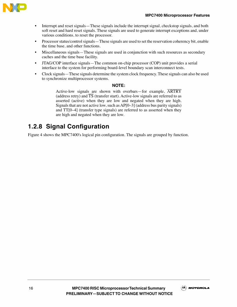
NOTE:Active-low signals are shown with overbarsÑfor example, ARTRY(address retry) and TS (transfer start). Active-low signals are referred to asasserted (active) when they are low and negated when they are high.Signals that are not active low, such as AP[0Ð3] (address bus parity signals)and TT[0Ð4] (transfer type signals) are referred to as asserted when theyare high and negated when they are low.
1.2.8 Signal ConÞgurationFigure 4 shows the MPC7400's logical pin conÞguration. The signals are grouped by function.
16 MPC7400 RISC Microprocessor Technical Summary PRELIMINARYÑSUBJECT TO CHANGE WITHOUT NOTICE

MPC7400 Microprocessor Features
Figure 4. MPC7400 Microprocessor Signal Groups
1.2.9 ClockingFor functional operation, the MPC7400 uses a single clock input signal, SYSCLK, from which clocking isderived for the processor core, the L2 Interface, and the MPX bus interface. Additionally, internal clockinformation is made available at the pins to support debug and development.
32
HIT
BUS REQUEST
BUS GRANT
TRANSFER START
ADDR. PARITY
GLOBAL
TRANSFER SIZE
ADDRESS ACK.
ADDRESS RETRY
SYSTEM CLOCK
DATA
DATA PARITY
TRANSFER ACK.
EXT INTERRUPT
RESERVATION
JTAG / COP
FACTORY TEST
1
1
1
5
3
4
TRANSFER BURST
WRITE THROUGH
PLL CONFIG.
TRANSFER TYPE 5
4
TIME BASE ENABLE
1 CLOCK OUT
MACHINE CHECK
SOFT RESET
L2 ADDRESS
SMI INTERRUPT
HARD RESET
PERF. MON. IN
QUIESCENT REQ
QUIESCENT ACK.
CHECKSTOP IN
Address Bus:ARBITRATION
Address Bus:TERMINATION
Address Bus:TXFR. START /ADDRESS /ATTRIBUTES
Data Bus:DATA
MPX Bus Signals
L2 DATA
L2 DATA PARITY
L2 ENABLE
L2 WRITE
L2 CLOCK OUT
L2 SYNC IN
L2 Interface and Other Signals
1
3
1
1
1
3
1
1
1
1
1
1
1
1
19
1
1
1
1
1
1
1
5
1
1
1
128
16
L2 Cache:ADDRESS /DATA
Processor:INTERRUPTS /RESETS
Processor:STATE /CONTROL
L2 Cache:CONTROL /CLOCKS
CLOCKCONTROL
TESTINTERFACE
CACHE-INHIBIT
ADDRESS
1 L2 CONTROL
DATA TRANS. INDEX
DATA SIZE
DATA READY
DATA BUS GRANT
2
1
1
1
64
8
TRANSFER ERR. ACK.
Data Bus:ARBITRATION
Data Bus:TERMINATION
6
6
ADDR. MONITOR
DATA MONITOR
BUS SELECT
1 L2 AVDD
AVDD
CHECKSTOP OUT
BUS MODE
1
1
SHARED
1 L2 DATA SIZE1
1
1AND
The data transaction Index includes DBWO for 60x compatibility. The bus monitor signals include ABB and DBB for 60x compatibility.
L2 VOLTAGE SELECT
BUS VOLT. SEL.
MONITORING
CHECK
1
1
2
Note: 426 total signal pins are shown (including analog VDDs)
L2ZZ 1
MPC7400 RISC Microprocessor Technical Summary 17PRELIMINARYÑSUBJECT TO CHANGE WITHOUT NOTICE

MPC7400 Microprocessor: Implementation
1.2.9.1 MPX Bus Interface
The internal processor core clock is synchronized to SYSCLK
with the aid of a VCO-based PLL. ThePLL_CFG[0Ð3] signals are used to program the internal clock rate to a 2x, 3x, 4x, 5x, 6x, 7x, 8x, 2.5x, 3.5x,4.5x, 5.5x, 6.5x, 7.5x, or 9x multiple of SYSCLK. The bus clock is maintained at the same frequency asSYSCLK. SYSCLK does not need to be a 50% duty-cycle signal.
1.2.9.2 L2 Interface
The MPC7400 generates the clock for the external L2 synchronous data RAMs. The clock frequency for theRAMs is divided down from (and phase-locked to) the core clock frequency of MPC7400. The core-to-L2frequency divisor for the L2 PLL is selected through L2CR[L2CLK]. The L2 RAM frequency can bedivided down by 1, 1.5, 2, 2.5, 3, 3.5, or 4 from the core operating frequency.
1.3 MPC7400 Microprocessor: Implementation
The PowerPC architecture is derived from the POWER architecture (Performance Optimized withEnhanced RISC architecture). The PowerPC architecture shares the beneÞts of the POWER architectureoptimized for single-chip implementations. The PowerPC architecture design facilitates parallel instructionexecution and is scalable to take advantage of future technological gains.
This section describes the PowerPC architecture in general, and speciÞc details about the implementationof the MPC7400 as a low-power, 32-bit member of the PowerPC processor family. The structure of thissection follows the organization of the userÕs manual; each subsection provides an overview of each chapter.
¥ Registers and programming modelÑSection 1.4, ÒPowerPC Registers and Programming Model,Ó describes the registers for the operating environment architecture common among PowerPC processors and describes the programming model. It also describes the registers that are unique to the MPC7400.
¥ Instruction set and addressing modesÑSection 1.5, ÒInstruction Set,Ó describes the PowerPC instruction set and addressing modes for the PowerPC operating environment architecture, and deÞnes and describes the PowerPC instructions implemented in the MPC7400.
¥ Cache implementationÑSection 1.6, ÒOn-Chip Cache Implementation,Ó describes the cache model that is deÞned generally for PowerPC processors by the virtual environment architecture. It also provides speciÞc details about the MPC7400 cache implementation.
¥ Exception modelÑSection 1.7, ÒException Model,Ó describes the exception model of the PowerPC operating environment architecture and the differences in the MPC7400 exception model.
¥ Memory managementÑSection 1.8, ÒMemory Management,Ó describes generally the conventions for memory management among the PowerPC processors. This section also describes the MPC7400Õs implementation of the 32-bit PowerPC memory management speciÞcation.
¥ Instruction timingÑSection 1.9, ÒInstruction Timing,Ó provides a general description of the instruction timing provided by the superscalar, parallel execution supported by the PowerPC architecture and the MPC7400.
¥ Power managementÑSection 1.10, ÒPower Management,Ó describes how the power management can be used to reduce power consumption when the processor, or portions of it, are idle.
¥ Thermal managementÑSection 1.11, ÒThermal Management,Ó describes how the thermal management unit and its associated registers (THRM1ÐTHRM3) and exception can be used to manage system activity in a way that prevents exceeding system and junction temperature thresholds. This is particularly useful in high-performance portable systems, which cannot use the same cooling mechanisms (such as fans) that control overheating in desktop systems.
18 MPC7400 RISC Microprocessor Technical Summary PRELIMINARYÑSUBJECT TO CHANGE WITHOUT NOTICE

PowerPC Registers and Programming Model
¥ Performance monitorÑSection 1.12, ÒPerformance Monitor,Ó describes the performance monitor facility, which system designers can use to help bring up, debug, and optimize software performance.
The following sections summarize the features of the MPC7400, distinguishing those that are deÞned by thearchitecture from those that are unique to the MPC7400 implementation.
The PowerPC architecture consists of the following layers, and adherence to the PowerPC architecture canbe described in terms of which of the following levels of the architecture is implemented:
¥ PowerPC user instruction set architecture (UISA)ÑDeÞnes the base user-level instruction set, user-level registers, data types, ßoating-point exception model, memory models for a uniprocessor environment, and programming model for a uniprocessor environment.
¥ PowerPC virtual environment architecture (VEA)ÑDescribes the memory model for a multiprocessor environment, deÞnes cache control instructions, and describes other aspects of virtual environments. Implementations that conform to the VEA also adhere to the UISA, but may not necessarily adhere to the OEA.
¥ PowerPC operating environment architecture (OEA)ÑDeÞnes the memory management model, supervisor-level registers, synchronization requirements, and the exception model. Implementations that conform to the OEA also adhere to the UISA and the VEA.
The PowerPC architecture allows a wide range of designs for such features as cache and system interfaceimplementations. The MPC7400 implementations support the three levels of the architecture describedabove. For more information about the PowerPC architecture, see
PowerPC Microprocessor Family: TheProgramming Environments
.
SpeciÞc features of the MPC7400 are listed in Section 1.2, ÒMPC7400 Microprocessor Features.Ó
1.4 PowerPC Registers and Programming Model
The PowerPC architecture deÞnes register-to-register operations for most computational instructions.Source operands for these instructions are accessed from the registers or are provided as immediate valuesembedded in the instruction opcode. The three-register instruction format allows speciÞcation of a targetregister distinct from the two source operands. Load and store instructions transfer data between registersand memory.
PowerPC processors have two levels of privilegeÑsupervisor mode of operation (typically used by theoperating system) and user mode of operation (used by the application software). The programming modelsincorporate 32 GPRs, 32 FPRs, 32 VRs, special-purpose registers (SPRs), and several miscellaneousregisters. Each PowerPC microprocessor also has its own unique set of implementation-speciÞc registers tosupport functionality that may not be deÞned by the PowerPC architecture.
Having access to privileged instructions, registers, and other resources allows the operating system tocontrol the application environment (providing virtual memory and protecting operating-system and criticalmachine resources). Instructions that control the state of the processor, the address translation mechanism,and supervisor registers can be executed only when the processor is operating in supervisor mode.
Figure 5 shows all the MPC7400 registers available at the user and supervisor level. The numbers to the rightof the SPRs indicate the number that is used in the syntax of the instruction operands to access the register.
MPC7400 RISC Microprocessor Technical Summary 19PRELIMINARYÑSUBJECT TO CHANGE WITHOUT NOTICE

PowerPC Registers and Programming Model
Figure 5. MPC7400 Microprocessor Programming ModelÑRegisters
SPR 937
SPR 938
SPR 941
SPR 942
Performance Counters
1
Sampled InstructionAddress
1
DSISR
Data AddressRegister
SPRGs
Exception Handling Registers
Save and Restore Registers
Instruction BATRegisters
Data BATRegisters
Memory Management Registers
Machine State Register
MSR
Processor VersionRegister
SPR 287PVR
Configuration Registers
HardwareImplementationRegisters
1
SPR 1
USER MODEL—UISA
Floating-PointStatus and
Control Register
FPSCR
ConditionRegister
General-PurposeRegisters
XER
XER
SPR 8
Link Register
LR
SUPERVISOR MODEL—OEA
DecrementerExternal AddressRegister
2
EAR
SDR1
SPR 9
Count Register
Miscellaneous Registers
SegmentRegisters
1
MPC7400Ðspecific registers
CR
Vector Registers
3
Performance Monitor Registers
Performance Counters
1
Monitor Control
1
SPR 939USIA
Sampled InstructionAddress
1
Performance Monitor Registers
Monitor Control
1
Time Base (For Writing)
USER MODEL—VEA
TBL TBR 268
Time Base Facility (For Reading)
CTRGPR0
GPR1
GPR31
TBU TBR 269
IBAT0U
IBAT0L
IBAT1U
IBAT1L
IBAT2U
IBAT2L
IBAT3U
IBAT3L
SPR 528
SPR 529
SPR 530
SPR 531
SPR 532
SPR 533
SPR 534
SPR 535
SPR 536
SPR 537
SPR 538
SPR 539
SPR 540
SPR 541
SPR 542
SPR 543
DBAT0U
DBAT0L
DBAT1U
DBAT1L
DBAT2U
DBAT2L
DBAT3U
DBAT3L
SR0
SR1
SR15
SDR1 SPR 25
HID0
HID1
SPR 1008
SPR 1009
VR0
VR1
VR31
UPMC1
UPMC2
UPMC3
UPMC4
UMMCR0
UMMCR1
UMMCR2
SPR 936
SPR 940
SPR 928SPR 953
SPR 954
SPR 957
SPR 958
PMC1
PMC2
PMC3
PMC4
SIA SPR 955MMCR0
MMCR1
MMCR2
SPR 952
SPR 956
SPR 944
SPRG0
SPRG1
SPRG2
SPRG3
SPR 272
SPR 273
SPR 274
SPR 275
DAR
DSISR
SPR 19
SPR 18
SRR0 SPR 26
SRR1 SPR 27
SPR 282TBL SPR 284
TBU SPR 285
DEC SPR 22
Data AddressBreakpoint Register
DABR SPR 1013
L2 ControlRegister 1, 2
L2CR SPR 1017
Instruction AddressBreakpoint Register 1
IABR SPR 1010
Breakpoint Address Mask Register
1
BAMR SPR 951
Breakpoint Address Mask Register
1
UBAMR SPR 935
Vector Status andControl Register
3
VSCR
Processor ID Register
2
PIR SPR 1023
MSSCR0 SPR1014 SPR1015
Memory Subsystem Registers
Memory Subsystem Control Register
1
MSSCR1
Memory Subsystem Debug Register
1
AltiVec Registers
AltIVec Save Register
3
VRSAVE SPR 256
2
Optional register defined by the PowerPC architecture.
ICTC SPR 1019SPR 1020
SPR 1021
SPR 1022
THRM1
THRM2
THRM3
Power/Thermal Management Registers
Thermal Assist Registers
1
Instruction Cache Throttling Control Register
1
Floating-PointRegisters
FPR0
FPR1
FPR31
3
These registers are defined by the AltiVec technology.
20 MPC7400 RISC Microprocessor Technical Summary PRELIMINARYÑSUBJECT TO CHANGE WITHOUT NOTICE

PowerPC Registers and Programming Model
The following tables summarize the PowerPC registers implemented in the MPC7400; Table 1 describesregisters (excluding SPRs) deÞned by the PowerPC architecture.
The OEA deÞnes numerous special-purpose registers that serve a variety of functions, such as providingcontrols, indicating status, conÞguring the processor, and performing special operations. During normalexecution, a program can access the registers, shown in Figure 5, depending on the programÕs accessprivilege (supervisor or user, determined by the privilege-level (PR) bit in the MSR). GPRs and FPRs areaccessed through operands that are part of the instructions. Access to registers can be explicit (that is,through the use of speciÞc instructions for that purpose such as Move to Special-Purpose Register (
mtspr
)and Move from Special-Purpose Register (
mfspr
) instructions) or implicit, as the part of the execution ofan instruction. Some registers can be accessed both explicitly and implicitly.
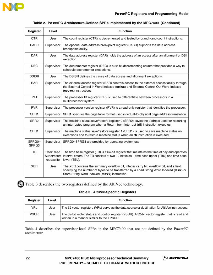
In the MPC7400, all SPRs are 32 bits wide. Table 2 describes the architecture-deÞned SPRs implementedby the MPC7400.
The
Programming Environments Manual
describes these registers in detail, including bitdescriptions. In particular, this section describes which features the PowerPC architecture deÞnes asoptional are implemented on the MPC7400.
Table 1. PowerPC Architecture-Defined Registers on the MPC7400 (Excluding SPRs)
Register Level Function
CR User The condition register (CR) consists of eight four-bit Þelds that reßect the results of certain operations, such as move, integer and ßoating-point compare, arithmetic, and logical instructions, and provide a mechanism for testing and branching.
FPRs User The 32 ßoating-point registers (FPRs) serve as the data source or destination for ßoating-point instructions. These 64-bit registers can hold either single- or double-precision ßoating-point values.
FPSCR User The ßoating-point status and control register (FPSCR) contains the ßoating-point exception signal bits, exception summary bits, exception enable bits, and rounding control bits needed for compliance with the IEEE-754 standard.
GPRs User The 32 GPRs serve as the data source or destination for integer instructions.
MSR Supervisor The machine state register (MSR) deÞnes the processor state. Its contents are saved when an exception is taken and restored when exception handling completes. The MPC7400 implements MSR[POW], (deÞned by the architecture as optional), which is used to enable the power management feature. The MPC7400-speciÞc MSR[PM] bit is used to mark a process for the performance monitor.
SR0ÐSR15
Supervisor The sixteen 32-bit segment registers (SRs) deÞne the 4-Gbyte space as sixteen 256-Mbyte segments. The MPC7400 implements segment registers as two arraysÑa main array for data accesses and a shadow array for instruction accesses; see Figure 1. Loading a segment entry with the Move to Segment Register
(
mtsr
)
instruction loads both arrays. The
mfsr
instruction reads the master register, shown as part of the data MMU in Figure 1.
Table 2. PowerPC Architecture-Defined SPRs Implemented by the MPC7400
Register Level Function
LR User The link register (LR) can be used to provide the branch target address and to hold the return address after branch and link instructions.
BATs Supervisor The architecture deÞnes 16 block address translation registers (BATs), which operate in pairs. There are four pairs of data BATs (DBATs) and four pairs of instruction BATs (IBATs). BATs are used to deÞne and conÞgure blocks of memory.
MPC7400 RISC Microprocessor Technical Summary 21PRELIMINARYÑSUBJECT TO CHANGE WITHOUT NOTICE
PowerPC Registers and Programming Model
Table 3 describes the two registers defined by the AltiVec technology.
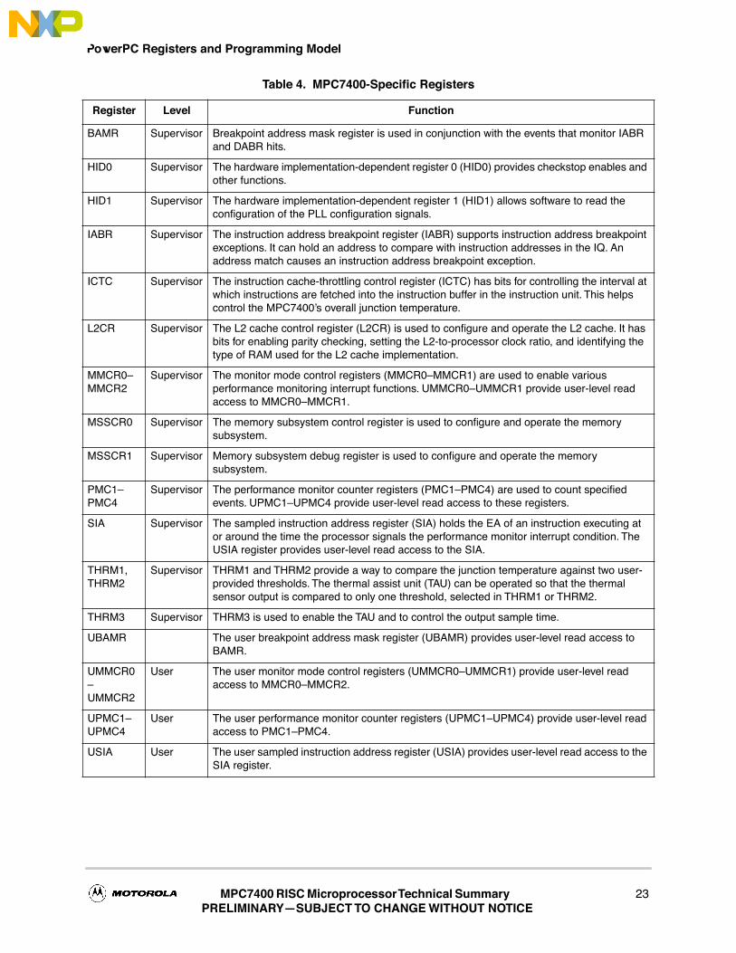
Table 4 describes the supervisor-level SPRs in the MPC7400 that are not deÞned by the PowerPCarchitecture.
CTR User The count register (CTR) is decremented and tested by branch-and-count instructions.
DABR Supervisor The optional
data address breakpoint register (DABR) supports the data address breakpoint facility.
DAR User The data address register (DAR) holds the address of an access after an alignment or DSI exception.
DEC Supervisor The decrementer register (DEC) is a 32-bit decrementing counter that provides a way to schedule decrementer exceptions.
DSISR User The DSISR deÞnes the cause of data access and alignment exceptions.
EAR Supervisor The external access register (EAR) controls access to the external access facility through the External Control In Word Indexed (
eciwx
) and External Control Out Word Indexed (
ecowx
) instructions.
PIR Supervisor The processor ID register (PIR) is used to differentiate between processors in a multiprocessor system.
PVR Supervisor The processor version register (PVR) is a read-only register that identiÞes the processor.
SDR1 Supervisor SDR1 speciÞes the page table format used in virtual-to-physical page address translation.
SRR0 Supervisor The machine status save/restore register 0 (SRR0) saves the address used for restarting an interrupted program when a Return from Interrupt (
rÞ
) instruction executes.
SRR1 Supervisor The machine status save/restore register 1 (SRR1) is used to save machine status on exceptions and to restore machine status when an
rÞ
instruction is executed.
SPRG0ÐSPRG3
Supervisor SPRG0ÐSPRG3 are provided for operating system use.
TB User: readSupervisor:read/write
The time base register (TB) is a 64-bit register that maintains the time of day and operates interval timers. The TB consists of two 32-bit ÞeldsÑtime base upper (TBU) and time base lower (TBL).
XER User The XER contains the summary overßow bit, integer carry bit, overßow bit, and a Þeld specifying the number of bytes to be transferred by a Load String Word Indexed (
lswx
) or Store String Word Indexed (
stswx
) instruction.
Table 3. AltiVec-Specific Registers
Register Level Function
VRs User The 32 vector registers (VRs) serve as the data source or destination for AltiVec instructions.
VSCR User The 32-bit vector status and control register (VSCR). A 32-bit vector register that is read and written in a manner similar to the FPSCR.
Table 2. PowerPC Architecture-Defined SPRs Implemented by the MPC7400 (Continued)
Register Level Function
22 MPC7400 RISC Microprocessor Technical Summary PRELIMINARYÑSUBJECT TO CHANGE WITHOUT NOTICE
PowerPC Registers and Programming Model
Table 4. MPC7400-Specific Registers
Register Level Function
BAMR Supervisor Breakpoint address mask register is used in conjunction with the events that monitor IABR and DABR hits.
HID0 Supervisor The hardware implementation-dependent register 0 (HID0) provides checkstop enables and other functions.
HID1 Supervisor The hardware implementation-dependent register 1 (HID1) allows software to read the conÞguration of the PLL conÞguration signals.
IABR Supervisor The instruction address breakpoint register (IABR) supports instruction address breakpoint exceptions. It can hold an address to compare with instruction addresses in the IQ. An address match causes an instruction address breakpoint exception.
ICTC Supervisor The instruction cache-throttling control register (ICTC) has bits for controlling the interval at which instructions are fetched into the instruction buffer in the instruction unit. This helps control the MPC7400Õs overall junction temperature.
L2CR Supervisor The L2 cache control register (L2CR) is used to conÞgure and operate the L2 cache. It has bits for enabling parity checking, setting the L2-to-processor clock ratio, and identifying the type of RAM used for the L2 cache implementation.
MMCR0ÐMMCR2
Supervisor The monitor mode control registers (MMCR0ÐMMCR1) are used to enable various performance monitoring interrupt functions. UMMCR0ÐUMMCR1 provide user-level read access to MMCR0ÐMMCR1.
MSSCR0 Supervisor The memory subsystem control register is used to conÞgure and operate the memory subsystem.
MSSCR1 Supervisor Memory subsystem debug register is used to conÞgure and operate the memory subsystem.
PMC1ÐPMC4
Supervisor The performance monitor counter registers (PMC1ÐPMC4) are used to count speciÞed events. UPMC1ÐUPMC4 provide user-level read access to these registers.
SIA Supervisor The sampled instruction address register (SIA) holds the EA of an instruction executing at or around the time the processor signals the performance monitor interrupt condition. The USIA register provides user-level read access to the SIA.
THRM1, THRM2
Supervisor THRM1 and THRM2 provide a way to compare the junction temperature against two user-provided thresholds. The thermal assist unit (TAU) can be operated so that the thermal sensor output is compared to only one threshold, selected in THRM1 or THRM2.
THRM3 Supervisor THRM3 is used to enable the TAU and to control the output sample time.
UBAMR The user breakpoint address mask register (UBAMR) provides user-level read access to BAMR.
UMMCR0ÐUMMCR2
User The user monitor mode control registers (UMMCR0ÐUMMCR1) provide user-level read access to MMCR0ÐMMCR2.
UPMC1ÐUPMC4
User The user performance monitor counter registers (UPMC1ÐUPMC4) provide user-level read access to PMC1ÐPMC4.
USIA User The user sampled instruction address register (USIA) provides user-level read access to the SIA register.
MPC7400 RISC Microprocessor Technical Summary 23PRELIMINARYÑSUBJECT TO CHANGE WITHOUT NOTICE

Instruction Set
1.5 Instruction SetAll PowerPC instructions are encoded as single-word (32-bit) opcodes. Instruction formats are consistentamong all instruction types, permitting efÞcient decoding to occur in parallel with operand accesses. ThisÞxed instruction length and consistent format greatly simpliÞes instruction pipelining.
1.5.1 PowerPC Instruction SetThe PowerPC instructions are divided into the following categories:
¥ Integer instructionsÑThese include computational and logical instructions.
Ñ Integer arithmetic instructions
Ñ Integer compare instructions
Ñ Integer logical instructions
Ñ Integer rotate and shift instructions
¥ Floating-point instructionsÑThese include ßoating-point computational instructions, as well as instructions that affect the FPSCR.
Ñ Floating-point arithmetic instructions
Ñ Floating-point multiply/add instructions
Ñ Floating-point rounding and conversion instructions
Ñ Floating-point compare instructions
Ñ Floating-point status and control instructions
¥ Load/store instructionsÑThese include integer and ßoating-point load and store instructions.
Ñ Integer load and store instructions
Ñ Integer load and store multiple instructions
Ñ Floating-point load and store
Ñ Primitives used to construct atomic memory operations (lwarx and stwcx. instructions)
¥ Flow control instructionsÑThese include branching instructions, condition register logical instructions, trap instructions, and other instructions that affect the instruction ßow.
Ñ Branch and trap instructions
Ñ Condition register logical instructions
¥ Processor control instructionsÑThese instructions are used for synchronizing memory accesses and management of caches, TLBs, and the segment registers.
Ñ Move to/from SPR instructions
Ñ Move to/from MSR
Ñ Synchronize
Ñ Instruction synchronize
Ñ Order loads and stores
¥ Memory control instructionsÑThese instructions provide control of caches, TLBs, and SRs.
Ñ Supervisor-level cache management instructions
Ñ User-level cache instructions
Ñ Segment register manipulation instructions
¥ Translation lookaside buffer management instructions
24 MPC7400 RISC Microprocessor Technical Summary PRELIMINARYÑSUBJECT TO CHANGE WITHOUT NOTICE

Instruction Set
This grouping does not indicate the execution unit that executes a particular instruction or group ofinstructions.
Integer instructions operate on byte, half-word, and word operands. Floating-point instructions operate onsingle-precision (one word) and double-precision (one double word) ßoating-point operands. The PowerPCarchitecture uses instructions that are four bytes long and word-aligned. It provides for byte, half-word, andword operand loads and stores between memory and a set of 32 GPRs. It also provides for word and double-word operand loads and stores between memory and a set of 32 ßoating-point registers (FPRs).
Computational instructions do not modify memory. To use a memory operand in a computation and thenmodify the same or another memory location, the memory contents must be loaded into a register, modiÞed,and then written back to the target location with distinct instructions.
PowerPC processors follow the program ßow when they are in the normal execution state. However, theßow of instructions can be interrupted directly by the execution of an instruction or by an asynchronousevent. Either kind of exception may cause one of several components of the system software to be invoked.
Effective address computations for both data and instruction accesses use 32-bit unsigned binary arithmetic.A carry from bit 0 is ignored in 32-bit implementations.
1.5.2 AltiVec Instruction Set¥ Vector integer arithmetic instructionsÑThese include arithmetic, logical, compare, rotate and shift
instructions.
¥ Vector ßoating-point arithmetic instructionsÑThese include ßoating-point arithmetic instructions, as well as a discussion on ßoating-point modes.
¥ Vector load and store instructionsÑThese include load and store instructions for vector registers. The AltiVec technology deÞne LRU and transient type instructions that can be used to optimize memory accesses.
Ñ LRU instructions. The AltiVec architecture speciÞes that the lvxl and stvxl instructions differ from other AltiVec load and store instructions in that they leave cache entries in a least-recently-used (LRU) state instead of a most-recently-used state.
Ñ Transient instructions. The AltiVec architecture describes a difference between static and transient memory accesses. A static memory access should have some reasonable degree of locality and be referenced several times or reused over some reasonably long period of time. A transient memory reference has poor locality and is likely to be referenced a very few times or over a very short period of time.
The following instructions are interpreted to be transient:
Ð dstt and dststt (transient forms of the two data stream touch instructions)
Ð lvxl and stvxl
¥ Vector permutation and formatting instructionsÑThese include pack, unpack, merge, splat, permute, select and shift instructions.
¥ Processor control instructionsÑThese instructions are used to read and write from the AltiVec status and control register.
¥ Memory control instructionsÑThese instructions are used for managing of caches (user level and supervisor level).
MPC7400 RISC Microprocessor Technical Summary 25PRELIMINARYÑSUBJECT TO CHANGE WITHOUT NOTICE

On-Chip Cache Implementation
1.5.3 MPC7400 Microprocessor Instruction SetThe MPC7400 instruction set is deÞned as follows:
¥ The MPC7400 provides hardware support for all 32-bit PowerPC instructions.
¥ The MPC7400 implements the following instructions optional to the PowerPC architecture:
Ñ External Control In Word Indexed (eciwx)
Ñ External Control Out Word Indexed (ecowx)
Ñ Data Cache Block Allocate (dcba)
Ñ Floating Select (fsel)
Ñ Floating Reciprocal Estimate Single-Precision (fres)
Ñ Floating Reciprocal Square Root Estimate (frsqrte)
¥ Store Floating-Point as Integer Word (stÞwx)
1.6 On-Chip Cache ImplementationThe following subsections describe the PowerPC architectureÕs treatment of cache in general, and theMPC7400-speciÞc implementation, respectively.
1.6.1 PowerPC Cache Model The PowerPC architecture does not deÞne hardware aspects of cache implementations. For example,PowerPC processors can have uniÞed caches, separate instruction and data caches (Harvard architecture),or no cache at all. PowerPC microprocessors control the following memory access modes on a page or blockbasis:
¥ Write-back/write-through mode
¥ Caching-inhibited mode
¥ Memory coherency
The caches are physically addressed, and the data cache can operate in either write-back or write-throughmode as speciÞed by the PowerPC architecture.
The PowerPC architecture deÞnes the term Ôcache blockÕ as the cacheable unit. The VEA and OEA deÞnecache management instructions a programmer can use to affect cache contents.
1.6.2 MPC7400 Microprocessor Cache ImplementationThe MPC7400 cache implementation is described in Section 1.2.4, ÒOn-Chip Instruction and Data Caches,Óand Section 1.2.5, ÒL2 Cache Implementation.Ó The BPU also contains a 64-entry BTIC that providesimmediate access to cached target instructions. For more information, see Section 1.2.2.2, ÒBranchProcessing Unit (BPU).Ó
1.7 Exception ModelThe following sections describe the PowerPC exception model and the MPC7400 implementation.
26 MPC7400 RISC Microprocessor Technical Summary PRELIMINARYÑSUBJECT TO CHANGE WITHOUT NOTICE

Exception Model
1.7.1 PowerPC Exception ModelThe PowerPC exception mechanism allows the processor to interrupt the instruction ßow to handle certainsituations caused by external signals, errors, or unusual conditions arising from the instruction execution.When exceptions occur, information about the state of the processor is saved to certain registers and theprocessor begins execution at an address (exception vector) predetermined for each exception. Exceptionprocessing occurs in supervisor mode.
Although multiple exception conditions can map to a single exception vector, a more speciÞc condition maybe determined by examining a register associated with the exceptionÑfor example, the DSISR and theFPSCR. Additionally, some exception conditions can be enabled or disabled explicitly by software.
The PowerPC architecture requires that exceptions be handled in program order; therefore, although aparticular implementation may recognize exception conditions out of order, they are handled in order. Whenan instruction-caused exception is recognized, any unexecuted instructions that appear earlier in theinstruction stream, including any that are undispatched, are required to complete before the exception istaken, and any exceptions those instructions cause must also be handled Þrst. Likewise, asynchronous,precise exceptions are recognized when they occur, but are not handled until the instructions currently in thecompletion queue successfully retire or generate an exception, and the completion queue is emptied.
Unless a catastrophic condition causes a system reset or machine check exception, only one exception ishandled at a time. For example, if one instruction encounters multiple exception conditions, those conditionsare handled sequentially. After the exception handler handles an exception, the instruction processingcontinues until the next exception condition is encountered. Recognizing and handling exception conditionssequentially guarantees that exceptions are recoverable.
When an exception is taken, information about the processor state before the exception was taken is savedin SRR0 and SRR1. Exception handlers should save the information stored in SRR0 and SRR1 early toprevent the program state from being lost due to a system reset and machine check exception or to aninstruction-caused exception in the exception handler, and before enabling external interrupts.
The PowerPC architecture supports four types of exceptions:
¥ Synchronous, preciseÑThese are caused by instructions. All instruction-caused exceptions are handled precisely; that is, the machine state at the time the exception occurs is known and can be completely restored. This means that (excluding the trap and system call exceptions) the address of the faulting instruction is provided to the exception handler and that neither the faulting instruction nor subsequent instructions in the code stream will complete execution before the exception is taken. Once the exception is processed, execution resumes at the address of the faulting instruction (or at an alternate address provided by the exception handler). When an exception is taken due to a trap or system call instruction, execution resumes at an address provided by the handler.
¥ Synchronous, impreciseÑThe PowerPC architecture deÞnes two imprecise ßoating-point exception modes, recoverable and nonrecoverable. Even though the MPC7400 provides a means to enable the imprecise modes, it implements these modes identically to the precise mode (that is, enabled ßoating-point exceptions are always precise).
¥ Asynchronous, maskableÑThe PowerPC architecture deÞnes external and decrementer interrupts as maskable, asynchronous exceptions. When these exceptions occur, their handling is postponed until the next instruction, and any exceptions associated with that instruction, completes execution. If no instructions are in the execution units, the exception is taken immediately upon determination of the correct restart address (for loading SRR0). As shown in Table 5., the MPC7400 implements additional asynchronous, maskable exceptions.
¥ Asynchronous, nonmaskableÑThere are two nonmaskable asynchronous exceptions: system reset and the machine check exception. These exceptions may not be recoverable, or may provide a limited degree of recoverability. Exceptions report recoverability through the MSR[RI] bit.
MPC7400 RISC Microprocessor Technical Summary 27PRELIMINARYÑSUBJECT TO CHANGE WITHOUT NOTICE

Exception Model
1.7.2 MPC7400 Microprocessor Exception ImplementationThe MPC7400 exception classes described above are shown in Table 5.
Although exceptions have other characteristics, such as priority and recoverability, Table 5 describescategories of exceptions the MPC7400 handles uniquely. Table 5 includes no synchronous impreciseexceptions; although the PowerPC architecture supports imprecise handling of ßoating-point exceptions,the MPC7400 implements these exception modes precisely.
Table 6. lists MPC7400 exceptions and conditions that cause them. Note that only three exceptions mayresult from execution of an AltiVec instruction.
¥ AltiVec unavailable exception. Taken if there is an attempt to execute any non-stream vector instruction with MSR[VA] = 0. After this exception, execution resumes at offset 0x00F20. This exception does not happen for stream instructions (dst[t], dstst[t], or dss). Note that the VRSAVE register is not protected by this exception, which is consistent AltiVec speciÞcation.
¥ A DSI exception. Taken if a vector load or store operation encounters a page fault (does not Þnd a valid PTE) or a protection violation. Also a DSI occurs if a vector load or store attempts to access T = 1 (PIO) space.
¥ AltiVec assist interrupt. Taken in some cases if a vector ßoating-point instruction detects denormalized data as an input or output in Java mode.
Exceptions speciÞc to the MPC7400 are indicated.
Table 5. MPC7400 Microprocessor Exception Classifications
Synchronous/Asynchronous Precise/Imprecise Exception Type
Asynchronous, nonmaskable Imprecise Machine check, system reset
Asynchronous, maskable Precise External, decrementer, system management, thermal management, and performance monitor interrupts
Synchronous Precise Instruction-caused exceptions
Table 6. Exceptions and Conditions
Exception TypeVector Offset
(hex)Causing Conditions
Reserved 00000 Ñ
System reset 00100 Assertion of either HRESET or SRESET or at power-on reset
Machine check 00200 Assertion of TEA during a data bus transaction, assertion of MCP, or an address, data, or L2 bus parity error. MSR[ME] must be set.
DSI 00300 As speciÞed in the PowerPC architecture. For TLB misses on load, store, or cache operations, a DSI exception occurs if a page fault occurs. MPC7400 takes a DSI if a lwarx or stwcx. instruction is executed to an address mapped W = 1 or if the data cache is locked.
ISI 00400 As deÞned by the PowerPC architecture.
External interrupt 00500 MSR[EE] = 1 and INT is asserted.
28 MPC7400 RISC Microprocessor Technical Summary PRELIMINARYÑSUBJECT TO CHANGE WITHOUT NOTICE

Memory Management
1.8 Memory ManagementThe following subsections describe the memory management features of the PowerPC architecture, and theMPC7400 implementation, respectively.
Alignment 00600 ¥ ¥A ßoating-point load/store, stmw, stwcx, lmw, lwarx, eciwx or ecowx instruction operand is not word-aligned.
¥ ¥A multiple/string load/store operation is attempted in little-endian mode. ¥ ¥The operand of dcbz is in memory that is write-through-required or
caching-inhibited or the cache is disabled
Program 00700 As deÞned by the PowerPC architecture.
Floating-point unavailable
00800 As deÞned by the PowerPC architecture.
Decrementer 00900 As deÞned by the PowerPC architecture, when the most signiÞcant bit of the DEC register changes from 0 to 1 and MSR[EE] = 1.
Reserved 00A00Ð00BFF
Ñ
System call 00C00 Execution of the System Call (sc) instruction.
Trace 00D00 MSR[SE] = 1 or a branch instruction completes and MSR[BE] = 1. Unlike the architecture deÞnition, isync does not cause a trace exception
Reserved 00E00 The MPC7400 does not generate an exception to this vector. Other PowerPC processors may use this vector for ßoating-point assist exceptions.
Reserved 00E10Ð00EFF
Ñ
Performance monitor1 00F00 The limit speciÞed in a PMC register is reached and MMCR0[ENINT] = 1
AltiVec unavailable1 00F20 Occurs due to an attempt to execute any non-stream AltiVec instruction while MSR[VA] = 0. This exception is not taken for stream instructions (dst[t], dstst[t] or dss).
Instruction address breakpoint1
01300 IABR[0Ð29] matches EA[0Ð29] of the next instruction to complete, IABR[TE] matches MSR[IR], and IABR[BE] = 1.
System management interrupt1
01400 MSR[EE] = 1 and SMI is asserted.
Reserved 01500Ð015FF Ñ
AltiVec assist1 01600 Supports denormalization detection in Java mode as deÞned by the AltiVec speciÞcation.
Thermal management interrupt1
01700 Thermal management is enabled, the junction temperature exceeds the threshold speciÞed in THRM1 or THRM2, and MSR[EE] = 1.
Reserved 01800Ð02FFF Ñ
1 MPC7400-speciÞc
Table 6. Exceptions and Conditions (Continued)
Exception TypeVector Offset
(hex)Causing Conditions
MPC7400 RISC Microprocessor Technical Summary 29PRELIMINARYÑSUBJECT TO CHANGE WITHOUT NOTICE

Instruction Timing
1.8.1 PowerPC Memory Management ModelThe primary functions of the MMU are to translate logical (effective) addresses to physical addresses formemory accesses and to provide access protection on blocks and pages of memory. There are two types ofaccesses generated by the MPC7400 that require address translationÑinstruction accesses, and dataaccesses to memory generated by load, store, and cache control instructions.
The PowerPC architecture deÞnes different resources for 32- and 64-bit processors; the MPC7400implements the 32-bit memory management model. The memory-management model provides 4 Gbytes oflogical address space accessible to supervisor and user programs with a 4-Kbyte page size and 256-Mbytesegment size. BAT block sizes range from 128 Kbyte to 256 Mbyte and are software selectable. In addition,it deÞnes an interim 52-bit virtual address and hashed page tables for generating 32-bit physical addresses.
The architecture also provides independent four-entry BAT arrays for instructions and data that maintainaddress translations for blocks of memory. These entries deÞne blocks that can vary from 128 Kbytes to 256Mbytes. The BAT arrays are maintained by system software.
The PowerPC MMU and exception model support demand-paged virtual memory. Virtual memorymanagement permits execution of programs larger than the size of physical memory; demand-paged impliesthat individual pages are loaded into physical memory from system memory only when they are Þrstaccessed by an executing program.
The hashed page table is a variable-sized data structure that deÞnes the mapping between virtual pagenumbers and physical page numbers. The page table size is a power of 2, and its starting address is a multipleof its size. The page table contains a number of page table entry groups (PTEGs). A PTEG contains eightpage table entries (PTEs) of eight bytes each; therefore, each PTEG is 64 bytes long. PTEG addresses areentry points for table search operations.
Setting MSR[IR] enables instruction address translations and MSR[DR] enables data address translations.If the bit is cleared, the respective effective address is the same as the physical address.
1.8.2 MPC7400 Microprocessor Memory Management Implementation
The MPC7400 implements separate MMUs for instructions and data. It implements a copy of the segmentregisters in the instruction MMU, however, read and write accesses (mfsr and mtsr) are handled throughthe segment registers implemented as part of the data MMU. The MPC7400 MMU is described inSection 1.2.3, ÒMemory Management Units (MMUs).Ó
The R (referenced) bit is updated in the PTE in memory (if necessary) during a table search due to a TLBmiss. Updates to the C (changed) bit are treated like TLB misses. A complete table search is performed andthe entire TLB entry is rewritten to update the C bit.
1.9 Instruction TimingThe MPC7400 is a pipelined, superscalar processor. A pipelined processor is one in which instructionprocessing is divided into discrete stages, allowing work to be done on different instructions in each stage.For example, after an instruction completes one stage, it can pass on to the next stage leaving the previousstage available to the subsequent instruction. This improves overall instruction throughput.
A superscalar processor is one that issues multiple independent instructions into separate execution units,allowing instructions to execute in parallel. The MPC7400 has eight independent execution units, two forinteger instructions, and one each for ßoating-point, branch, load/store, system register, vector permute, andvector arithmetic logic unit instructions. Having separate GPRs, FPRs, and VRs allows integer, ßoating-point, and vector calculations, and load and store operations to occur simultaneously without interference.
30 MPC7400 RISC Microprocessor Technical Summary PRELIMINARYÑSUBJECT TO CHANGE WITHOUT NOTICE

Instruction Timing
Additionally, rename buffers are provided to allow operations to post execution results for use by subsequentinstructions without committing them to the architected FPRs, GPRs, and VRs.
As shown in Figure 6., the common pipeline of the MPC7400 has four stages through which all instructionsmust passÑfetch, decode/dispatch, execute, and complete/write back. Some instructions occupy multiplestages simultaneously and some individual execution units have additional stages. For example, the ßoating-point pipeline consists of three stages through which all ßoating-point instructions must pass.
Figure 6. Pipeline Diagram
Note that Figure 6. does not show features, such as reservation stations and rename buffers that reduce stallsand improve instruction throughput.
The instruction pipeline in the MPC7400 has four major pipeline stages, described as follows:
¥ The fetch pipeline stage primarily involves retrieving instructions from the memory system and determining the location of the next instruction fetch. The BPU decodes branches during the fetch stage and removes those that do not update CTR or LR from the instruction stream.
¥ The dispatch stage is responsible for decoding the instructions supplied by the instruction fetch stage and determining which instructions can be dispatched in the current cycle. A rename ID is given to instructions with a target destination. If source operands for the instruction are available, they are read from the appropriate register Þle or rename register to the execute pipeline stage. If a source operand is not available, dispatch provides a tag that indicates which rename register will supply the operand when it becomes available. At the end of the dispatch stage, the dispatched instructions and their operands are latched by the appropriate execution unit.
Fetch
Complete (Write-Back)
Dispatch
Execute Stage
Maximum three-instruction dispatchper clock cycle (includes one branchinstruction)
Maximum two-instructioncompletion per clock cycle
Maximum four-instruction fetchper clock cycle
BPU
FPU3SRU IU2IU1
FPU2
FPU1
LSU1
LSU2VFPU4VSIU VCIU3
VFPU3
VFPU2
VPU
VALUVFPU1
VCIU2
VCIU1
MPC7400 RISC Microprocessor Technical Summary 31PRELIMINARYÑSUBJECT TO CHANGE WITHOUT NOTICE

Power Management
¥ Instructions executed by the IUs, FPU, SRU, LSU, VPU, and VALU are dispatched from the bottom two positions in the instruction queue. In a single clock cycle, a maximum of two instructions can be dispatched to these execution units in any combination. When an instruction is dispatched, it is assigned a position in the eight-entry completion queue. A branch instruction can be issued on the same clock cycle for a maximum three-instruction dispatch.
¥ During the execute pipeline stage, each execution unit that has an executable instruction executes the selected instruction (perhaps over multiple cycles), writes the instruction's result into the appropriate rename register, and notiÞes the completion stage that the instruction has Þnished execution. In the case of an internal exception, the execution unit reports the exception to the completion pipeline stage and (except for the FPU) discontinues instruction execution until the exception is handled. The exception is not signaled until that instruction is the next to be completed. Execution of most ßoating-point instructions is pipelined within the FPU allowing up to three instructions to be executing in the FPU concurrently. The FPU stages are multiply, add, and round-convert. Execution of most load/store instructions is also pipelined. The load/store unit has two pipeline stages. The Þrst stage is for effective address calculation and MMU translation and the second stage is for accessing the data in the cache.
¥ The complete pipeline stage maintains the correct architectural machine state and transfers execution results from the rename registers to the GPRs and FPRs (and CTR and LR, for some instructions) as instructions are retired. As with dispatching instructions from the instruction queue, instructions are retired from the two bottom positions in the completion queue. If completion logic detects an instruction causing an exception, all following instructions are cancelled, their execution results in rename registers are discarded, and instructions are fetched from the appropriate exception vector.
Because the PowerPC architecture can be applied to such a wide variety of implementations, instructiontiming varies among PowerPC processors.
1.10 Power ManagementThe MPC7400 provides four power modes, selectable by setting the appropriate control bits in the MSR andHID0 registers. The four power modes are as follows:
¥ Full-powerÑThis is the default power state of the MPC7400. The MPC7400 is fully powered and the internal functional units are operating at the full processor clock speed. If the dynamic power management mode is enabled, functional units that are idle will automatically enter a low-power state without affecting performance, software execution, or external hardware.
¥ DozeÑAll the functional units of the MPC7400 are disabled except for the time base/decrementer registers, the thermal assist unit, and the bus snooping logic. When the processor is in doze mode, an external asynchronous interrupt, a system management interrupt, a decrementer exception, a hard or soft reset, or machine check brings the MPC7400 into the full-power state. The MPC7400 in doze mode maintains the PLL in a fully powered state and locked to the system external clock input (SYSCLK) so a transition to the full-power state takes only a few processor clock cycles.
¥ NapÑThe nap mode further reduces power consumption by disabling bus snooping, leaving only the decrementer/time base registers, the thermal assist unit, the PLL, and the DLL (for L2 RAM clocks) in a powered state. The MPC7400 returns to the full-power state upon receipt of an external asynchronous interrupt, a system management interrupt, a decrementer exception, a hard or soft reset, or a machine check input (MCP). A return to full-power state from a nap state takes only a few processor clock cycles. When the processor is in nap mode, if QACK is negated, the processor is put in doze mode to support snooping.
32 MPC7400 RISC Microprocessor Technical Summary PRELIMINARYÑSUBJECT TO CHANGE WITHOUT NOTICE

Thermal Management
¥ SleepÑSleep mode minimizes power consumption by disabling all internal functional units, after which external system logic may disable the PLL and SYSCLK. Returning the MPC7400 to the full-power state requires the enabling of the PLL and SYSCLK, followed by the assertion of an external asynchronous interrupt, a system management interrupt, a hard or soft reset, or a machine check input (MCP) signal after the time required to relock the PLL.
1.11 Thermal Management The MPC7400Õs thermal assist unit (TAU) provides a way to control heat dissipation. This ability isparticularly useful in portable computers, which, due to power consumption and size limitations, cannot usedesktop cooling solutions such as fans. Therefore, better heat sink designs coupled with intelligent thermalmanagement is of critical importance for high performance portable systems.
Primarily, the thermal management system monitors and regulates the systemÕs operating temperature. Forexample, if the temperature is about to exceed a set limit, the system can be made to slow down or evensuspend operations temporarily in order to lower the temperature.
The thermal management facility also ensures that the processorÕs junction temperature does not exceed theoperating speciÞcation. To avoid the inaccuracies that arise from measuring junction temperature with anexternal thermal sensor, the MPC7400Õs on-chip thermal sensor and logic tightly couples the thermalmanagement implementation.
The TAU consists of a thermal sensor, digital-to-analog convertor, comparator, control logic, and thededicated SPRs described in Section 1.4, ÒPowerPC Registers and Programming Model.Ó The TAU does thefollowing:
¥ Compares the junction temperature against user-programmable thresholds
¥ Generates a thermal management interrupt if the temperature crosses the threshold
¥ Enables the user to estimate the junction temperature by way of a software successive approximation routine
The TAU is controlled through the privileged mtspr/mfspr instructions to the three SPRs provided forconÞguring and controlling the sensor control logic, which function as follows:
¥ THRM1 and THRM2 provide the ability to compare the junction temperature against two user-provided thresholds. Having dual thresholds gives the thermal management software Þner control of the junction temperature. In single threshold mode, the thermal sensor output is compared to only one threshold in either THRM1 or THRM2.
¥ THRM3 is used to enable the TAU and to control the comparator output sample time. The thermal management logic manages the thermal management interrupt generation and time multiplexed comparisons in the dual threshold mode as well as other control functions.
Instruction cache throttling provides control of the MPC7400Õs overall junction temperature by determiningthe interval at which instructions are fetched. This feature is accessed through the ICTC register.
1.12 Performance MonitorThe MPC7400 incorporates a performance monitor facility that system designers can use to help bring up,debug, and optimize software performance. The performance monitor counts events during execution ofcode, relating to dispatch, execution, completion, and memory accesses.
The performance monitor incorporates several registers that can be read and written to by supervisor-levelsoftware. User-level versions of these registers provide read-only access for user-level applications. Theseregisters are described in Section 1.4, ÒPowerPC Registers and Programming Model.Ó Performance monitorcontrol registers, MMCR0 or MMCR1, can be used to specify which events are to be counted and the
MPC7400 RISC Microprocessor Technical Summary 33PRELIMINARYÑSUBJECT TO CHANGE WITHOUT NOTICE

Differences between the MPC7400 and the MPC750
conditions for which a performance monitoring interrupt is taken. Additionally, the sampled instructionaddress register, SIA (USIA), holds the address of the Þrst instruction to complete after the counteroverßowed.
Attempting to write to a user-read-only performance monitor register causes a program exception,regardless of the MSR[PR] setting.
When a performance monitoring interrupt occurs, program execution continues from vector offset 0x00F00.
1.13 Differences between the MPC7400 and the MPC750
The design philosophy on MPC7400 is to change from the MPC750 base only where required to gaincompelling multimedia and multiprocessor performance. MPC7400Õs core is essentially the same as theMPC750Õs, except that whereas the MPC750 has a 6-entry completion queue and has slower performanceon some ßoating-point double-precision operations, MPC7400 has an 8-entry completion queue and a fulldouble-precision FPU. MPC7400 also adds the AltiVec instruction set, has a new memory subsystem(MSS), and can interface to an improved bus, the MPX bus. The following sections discuss the majorchanges in more detail. Differences are summarized in Table 7.
Table 7. MPC750/MPC7400 Differences
Feature Difference
Core
Sequencing The MPC750 has a 6-entry instruction buffer and a 6-entry completion queue. For each clock, it can fetch four instructions, dispatch two instructions, fold one branch, and complete two instructions. MPC7400 is identical, except for an eight-entry completion buffer, as shown in Figure 1. The extra completion queue entries reduce the opportunity for bottlenecks by MPC7400Õs additional execution units.
FPU On the MPC750, single-precision operations involving multiplication have a 3-cycle latency, while their double-precision equivalents take an additional cycle. Because MPC7400 has a full double-precision FPU, double-precision multiplies have the same latency as single-precision multiplies: 3 cycles. Floating-point divides, on the other hand, still have the same latency for the two designs (17 cycles for single-precision, 31 cycles for double-precision).
MPC750 Double-precision ßoating-point multiply 4 cycles
All other ßoating-point add and multiply 3 cycles
MPC7400 All ßoating-point add and multiply 3 cycles
AltiVec MPC7400 implements all instructions deÞned by the AltiVec speciÞcation. Two dispatchable AltiVec functional units were added, a vector permute unit (VPU) and a vector ALU unit VALU. The VALU comprises a simple integer unit, a complex integer unit, and a ßoating-point unit. As shown in Figure 1, MPC7400 also adds a vector register (VR) Þle consisting of 32 128-bit VRs, along with 6 VR rename registers.
The VPU handles permute and shift operations and the VALU handles calculations. The LSU handles AltiVec load and store operations. To support AltiVec operations, all memory subsystem (MSS) data buses are 128 bits wide (as opposed to 64 bits in the MPC750). (See diagram in the MSS section.) Also, additional queues have been added and queue sizes have been increased to sustain heavy AltiVec usage.
AltiVec is designed to improve the performance of vector-intensive code, as can be seen in such applications as multimedia and digital signal processing. AltiVec-targeted code can speed up many two-dimensional and three-dimensional graphics functions 3Ð5 times, especially core functions in 3-D engines and game-related 2-D functions.
34 MPC7400 RISC Microprocessor Technical Summary PRELIMINARYÑSUBJECT TO CHANGE WITHOUT NOTICE

Differences between the MPC7400 and the MPC750
Memory Subsystem (MSS)MPC7400 has a new memory subsystem designed to support AltiVec work loads, the new MPX bus protocol, and 5-state multiprocessing capabilities. Queues and queue sizes are designed to support more efÞcient data ßow. For example, the MPC750 has a three-entry LSU store queue, while MPC7400 has a six-entry LSU store queue.
One such buffer that MPC7400 adds (which the MPC750 lacks) is an eight-entry reload buffer, where L1 data cache misses can reside while they wait for their data to be loaded. This enables two features: load miss folding and store miss merging.
Load miss folding
In the MPC750, if a second load misses to the same cache block, the second load must wait for the critical word of the Þrst load before it can access its data, and subsequent accesses are also stalled. In MPC7400, the Þrst load or store causes an entry to be allocated in the reload buffer. A subsequent load to the same cache block is placed aside in the load fold queue (LFQ), and it can return its data immediately when available. Also, subsequent accesses to the cache are not blocked and can be processed.
For example, on the MPC750 if a load or store (access A) misses in the data cache. Then a subsequent load (access B) to the same cache block must wait until the critical word for A is retired. Because of this, any subsequent loads or stores after access B also cannot access the data cache until the reload for access A completes.
On the other hand, with MPC7400, load or store access A misses in the data cache, and while the data is coming back, up to four subsequent misses to the same cache block can be folded into the LFQ, and subsequent instructions can access the data cache. Loads are blocked only when the reload table or the LFQ are full.
Store miss merging
In the MPC750, if a second store misses to the same cache block, it must wait for the critical word of the Þrst store before it can write its data. MPC7400 can merge several stores to the same cache block into the same entry in its reload buffer. If enough stores merge to write all 32 bytes of the cache block (usually via two back-to-back AltiVec store misses), then no data needs to be loaded from the bus and an address-only transaction (KILL) is broadcast instead.
Cache
Allocate on reload
Both designs have the same L1 cache size, but differ in their block allocation policy: The MPC750 has an allocate-on-miss policy, while MPC7400 has allocate-on-reload policy, which allows better cache allocation and replacement and more efÞcient use of data bus bandwidth.
If access A misses in the cache, the MPC750 immediately identiÞes the victim block (call it X) if there is one and allocates its space for the new data (call it Y) to be loaded. If a subsequent access (access B) needs this victim block, even if access B occurs before Y has been loaded, then it will miss because as soon as X is allocated it is no longer valid. After Y has loaded (and, if X is modiÞed, after X has been cast out), X must be reloaded, and B must wait until its data is valid again.
MPC7400, on the other hand, delays allocation/victimization until the block reload occurs. In the example above, while Y is being loaded, B can hit block X, and a different block is victimized. This allows more efÞcient use of the cache and can reduce thrashing.
On MPC7400, allocation occurring in parallel with reload which uses the cache more efÞciently.
MPC750 MPC7400
1-cycle load arbitration 1-cycle load arbitration
1-cycle allocate/victimize 4-beat reload
4-beat reload (64 bits/beat)
Total = 6 cycles Total = 5 cycles
Table 7. MPC750/MPC7400 Differences (Continued)
Feature Difference
MPC7400 RISC Microprocessor Technical Summary 35PRELIMINARYÑSUBJECT TO CHANGE WITHOUT NOTICE

Differences between the MPC7400 and the MPC750
Outstanding misses
The MPC750 allows one D-side miss and one I-side miss to be outstanding (accessing the L2 or the bus) at any given time. MPC7400 allows one I-side miss and up to eight D-side misses (maximum of 8 total). Note that the L2 can queue up to four hits, but with a fast L2 (1:1 mode) it is impossible to Þll this queue with data cache misses. The L2 miss queue can queue four transactions that are waiting to access the processor address bus.
Miss under miss
While processing a miss, the MPC750Õs data cache allows subsequent loads and stores to hit in the data cache (hit under miss), but it blocks on the next miss until the Þrst miss Þnishes reloading. MPC7400 allows subsequent accesses that miss in the data cache to propagate to the L2 and beyond (miss under miss).
L2 cache Compared to the MPC750, MPC7400 has twice the number of on-chip L2 tags per way (8192), which can support twice the L2 cache size (up to 2 Mbyte). The sectoring conÞguration is slightly different, too:
MPC750MPC7400
1 Mbyte4 sectors/tag2 Mbyte4 sectors/tag
512 Kbyte2 sectors/tag1 Mbyte2 sectors/tag
256 Kbyte2 sectors/tag512 Kbyte1 sector/tag
Fewer sectors per tag allows the cache to be used more efÞciently.
MPC7400 and the MPC750 also have different cache reload policies. On the MPC750, an L1 cache miss that also misses in the L2 causes a reload from the bus to both L1 and L2. On MPC7400, misses to the L1 instruction cache behave the same way, but misses to the L1 data cache behave differently: data is reloaded into the L1 only. Thus, with respect to the L1 data cache, the L2 holds only blocks that are cast out; it acts as a giant victim cache for the L1 data cache. This improves performance because the same data is duplicated in the L1 data cache and L2 less often.
60x bus/
MPX bus
MPC7400 supports the 60x bus used by the MPC750, but it also supports a new bus (MPX bus). It implements a 5-state cache-coherency protocol (MERSI) and the MESI and MEI subsets. This provides better hardware support of multiprocessing.
For example, MPX bus supports data intervention. On the 60x bus, if one processor does a read of data that is marked ModiÞed in another processorÕs cache, the transaction is retried and the data is pushed to memory, after which the transaction is restarted. MPX bus allows the data to be forwarded directly to the requesting processor from the processor that has it cached. (MPC7400 also supports intervention for data marked Exclusive or Shared.)
The MPC7400 can support up to seven simultaneous transactions on the bus interface (60x or MPX bus) while the MPC750 supports only two.
Table 7. MPC750/MPC7400 Differences (Continued)
Feature Difference
36 MPC7400 RISC Microprocessor Technical Summary PRELIMINARYÑSUBJECT TO CHANGE WITHOUT NOTICE

Differences between the MPC7400 and the MPC750
MPC7400 RISC Microprocessor Technical Summary 37PRELIMINARYÑSUBJECT TO CHANGE WITHOUT NOTICE

Differences between the MPC7400 and the MPC750
38 MPC7400 RISC Microprocessor Technical Summary PRELIMINARYÑSUBJECT TO CHANGE WITHOUT NOTICE

Differences between the MPC7400 and the MPC750
MPC7400 RISC Microprocessor Technical Summary 39PRELIMINARYÑSUBJECT TO CHANGE WITHOUT NOTICE

Information in this document is provided solely to enable system and software implementers to use PowerPC microprocessors. There are no expressor implied copyright licenses granted hereunder to design or fabricate PowerPC integrated circuits or integrated circuits based on the information inthis document.Motorola reserves the right to make changes without further notice to any products herein. Motorola makes no warranty, representation or guaranteeregarding the suitability of its products for any particular purpose, nor does Motorola assume any liability arising out of the application or use of anyproduct or circuit, and specifically disclaims any and all liability, including without limitation consequential or incidental damages. ÒTypicalÓ parameterscan and do vary in different applications. All operating parameters, including ÒTypicalsÓ must be validated for each customer application by customerÕstechnical experts. Motorola does not convey any license under its patent rights nor the rights of others. Motorola products are not designed, intended,or authorized for use as components in systems intended for surgical implant into the body, or other applications intended to support or sustain life,or for any other application in which the failure of the Motorola product could create a situation where personal injury or death may occur. Should Buyerpurchase or use Motorola products for any such unintended or unauthorized application, Buyer shall indemnify and hold Motorola and its officers,employees, subsidiaries, affiliates, and distributors harmless against all claims, costs, damages, and expenses, and reasonable attorney fees arisingout of, directly or indirectly, any claim of personal injury or death associated with such unintended or unauthorized use, even if such claim alleges thatMotorola was negligent regarding the design or manufacture of the part.Motorola and are registered trademarks of Motorola, Inc. Motorola, Inc. is an Equal Opportunity/Affirmative Action Employer.
Motorola Literature Distribution Centers:USA/EUROPE: Motorola Literature Distribution; P.O. Box 5405; Denver, Colorado 80217; Tel.: 1-800-441-2447 or 1-303-675-2140; World Wide Web Address: http://ldc.nmd.com/JAPAN: Nippon Motorola Ltd SPD, Strategic Planning Office 4-32-1, Nishi-Gotanda Shinagawa-ku, Tokyo 141, Japan Tel.: 81-3-5487-8488ASIA/PACIFIC: Motorola Semiconductors H.K. Ltd Silicon Harbour Centre 2, Dai King Street Tai Po Industrial Estate Tai Po, New Territories, HongKong
Mfaxª: [email protected]; TOUCHTONE 1-602-244-6609; US & Canada ONLY (800) 774-1848; World Wide Web Address: http://sps.motorola.com/mfaxINTERNET: http://motorola.com/sps
Technical Information: Motorola Inc. SPS Customer Support Center 1-800-521-6274; electronic mail address: [email protected] Comments: FAX (512) 895-2638, Attn: RISC Applications Engineering.World Wide Web Addresses: http://www.motorola.com/PowerPChttp://www.motorola.com/netcommhttp://www.motorola.com/Coldfire
MPC7400TS/D
Mfax is a trademark of Motorola, Inc.The PowerPC name, the PowerPC logotype, and PowerPC 603e are trademarks of International Business Machines Corporation used by Motorolaunder license from International Business Machines Corporation.