Embed Size (px)
Citation preview
SD\1552524.8
12670 High Bluff Drive
San Diego, California 92130
Tel: +1.858.523.5400 Fax: +1.858.523.5450
www.lw.com
FIRM / AFFILIATE OFFICES
Abu Dhabi Milan
Barcelona Moscow
Beijing Munich
Boston New Jersey
Brussels New York
Century City Orange County
Chicago Paris
Doha Riyadh
Dubai Rome
Düsseldorf San Diego
Frankfurt San Francisco
Hamburg Shanghai
Hong Kong Silicon Valley
Houston Singapore
London Tokyo
Los Angeles Washington, D.C.
Madrid
December 31, 2014 Craig Melodia Associate Regional Counsel United States Environmental Protection Agency Region 5 77 West Jackson Boulevard Chicago, IL 60604-3590
Re: Ashland Lakefront Superfund Site: Response to September 23, 2014 Weston Dry Dredge Report
Dear Mr. Melodia:
On behalf of Northern States Power Company of Wisconsin (“NSPW” or the “Company”), we are writing to provide a further response to Weston Solutions, Inc.’s (“Weston”) Technical Submittal, dated September 23, 2014 (“2014 Weston Report”). In the company’s prior submittal, dated October 28, 2014, NSPW submitted a preliminary analysis of the 2014 Weston Report, which identified several serious concerns with Weston’s unproven and untested approach. In that submittal, NSPW indicated that it intended to further review, in detail, the 2014 Weston Report (including the supplemental CD provided on October 8, 2014, which contained over 400 pages of exhibits), and that it would submit a supplemental report upon completion of its review. NSPW and its consultants have since reviewed these materials in greater detail, and this submittal constitutes our supplemental response. As described further below, Anchor QEA and Dr. Richard J. Finno, have both independently reviewed the 2014 Weston Report in detail, and both conclude that there are flaws with Weston’s unproven and aggressive approach, that the dry dredge is not safe or implementable at this Site, and that there are other better alternative remedies that would safely and effectively remediate the sediments at this Site. We also summarize below the history of our discussions over this issue as we think it provides helpful context for NSPW’s determination that the dry dredge remedy is too dangerous to implement at this Site.
I. EXPERIENCED TECHNICAL EXPERTS PREVIOUSLY CONCLUDED THAT THE DRY DREDGE IS NOT SAFE OR IMPLEMENTABLE AT THIS SITE
A. Numerous Technical Concerns With The Dry Dredge Proposal Were Raised in 2008-2010
The possibility of implementing a dry dredge remedy at the Site has been the subject of numerous reports and analyses on the part of the U.S. Environmental Protection Agency
December 31, 2014 Page 2
SD\1552524.8
(“EPA”), NSPW, and others. In 2008, a feasibility study assessed dry excavation as a possible remedial approach, and concluded that a dry dredge would present “potentially greater risk to human health, because of the need to work behind barriers engineered to keep out the waters of Lake Superior.”1 Foth Infrastructure and Engineering, LLC (“Foth”), reached similar conclusions in its 2009 evaluation of a potential dry excavation, noting that elevated artesian pressures within the Copper Falls formation could result in instability, basal heave, and failure of the dry excavation system.
Notwithstanding the feasibility study and Foth’s conclusions, the Record of Decision (“ROD”) for the Site issued in September 2010 selected a wet-dry hybrid remedy for the sediments, while allowing for the potential of a remedy change (via an explanation of significant differences (“ESD”)) to a wet dredge only approach, following the successful completion of a pilot study.2 When the ROD was issued, NSPW was made aware of a report for the first time prepared by EPA’s consultant, Weston Solutions, Inc. (“Weston”), titled “Conceptual Geotechnical Assessment For Sediment Removal at the Ashland/Northern States Power Lakefront Site in Ashland, Wisconsin” (“2009 Weston Report”). It appears that the remedy selection in the ROD was based, at least in some material part, on the analysis in the 2009 Weston Report.
Although Weston’s “preliminary and conceptual” analysis concluded that “near-shore, bay bottom sediments likely can be safely removed using dry excavation techniques, assuming that conceptual planning, final design engineering and implementation of the construction work are all properly executed,” it provided no specific guidance for safe implementation. Further, Weston acknowledged that the “structural stability of the sheet pile wall, excavation bottom blowout, and piping of bay bottom sandy sediments are significant worker/equipment safety concerns and represent potential ‘fatal flaw’ failure mechanisms” unique to the near shore dry excavation remedy. 2009 Weston Report, at 2 (emphasis added). Weston further recommended that, in order to even attempt a dry dredge, the Site should be divided up into a matrix of interior sheet pile walls, which was not reflected in the remedy described in the ROD. Those modifications to the dry dredge remedy were not evaluated under the National Contingency Plan (“NCP”) criteria in the ROD.
1 Note that other remedies have also been identified as possible alternative remedies. For example, as early as the late 1990s, a consultant for the Wisconsin Department of Natural Resources (“WDNR”) recommended a CDF remedy for the Site. See Short Elliot and Hendrickson (SEH), Sediment Investigation Report (1996). An engineered shoreline remedy identified in the feasibility study also scored well on the National Contingency Plan criteria, except for the mistaken belief at that time that there was not a way to permit a CDF under Wisconsin law. EPA, WDNR, and NSPW now understand that a CDF can be permitted under Wisconsin law and, in fact, there is a CDF within the Site already that was created and permitted in the late 1980s. 2 Based on previous discussions with EPA and the text of the ROD itself, NSPW understands that, if the wet dredge pilot is successful, EPA will issue an Explanation of Significant Differences authorizing the Company to perform a full-scale wet dredge at the Site
December 31, 2014 Page 3
SD\1552524.8
B. In 2012 Multiple Nationally-Recognized Sediment Engineering Firms Concluded That The Dry Dredge Was Not Safe Or Implementable
In 2012, multiple technical experts with particular expertise in sediments—including Anchor, Gradient, and Burns & McDonnell—separately reviewed the 2009 Weston report and expressed serious concerns about the safety, environmental risks, and feasibility of a dry dredge.3 In fact, each consultant concluded that a dry dredge is an inappropriate remedy for the Site and could result in catastrophic and irreparable harm to human health and the environment. See Anchor QEA, Independent Evaluation of Sediment Removal Alternatives: Ashland/NSPW Lakefront Superfund Site (October 2012); Gradient, Critique of the National Contingency Plan Consistency of US EPA’s September 2010 Record of Decision for the Ashland/Northern States Power Lakefront Site (October 2012); and Burns & McDonnell, Technical Assessment of EPA’s Comparative Analysis of Near Shore Dry Excavation and Site-Specific Failure Mechanisms (October 2012).
Among other things, the experts concluded that a dry dredge creates a significant risk of “bottom uplift,” a catastrophic failure of the bay floor that would threaten the safety of the workers performing the remedy and cause wide distribution of the contaminants in the bay sediments. The dry dredge is also based on unrealistic expectations regarding the ability of a sheet pile wall to hold back Lake Superior, among other potential failure mechanisms. A dry dredge would also cause significant community disruption and potentially expose the community to greater impacts from noise, air emissions, odors, and the long-term closure of Kreher Park. These experts concluded that there are less expensive, less dangerous, and more effective alternatives to the selected dry dredge. As such, they concluded the dry dredge is inconsistent with the NCP and would be an unsafe and inappropriate remedy for this Site.
C. After Collecting Additional Site Data In 2012 And 2013, Anchor Further Concluded That The Additional Data Demonstrated That The Dry Dredge Was Not Safe Or Implementable
As a result of the concerns identified by NSPW’s consultants in 2012, EPA requested that NSPW perform additional sampling along the shoreline in 2012, and additional sampling in the Bay in 2013. NSPW’s consultants gathered this additional data in 2012 and 2013. This additional data was then evaluated by NSPW’s consultants. The new data further confirmed prior concerns about the safety and implementability of the dry dredge. See Anchor QEA, Shoreline and Offshore Geotechnical Evaluation Report (December 2013). In particular, the data showed significant variability in site conditions that did not follow predictable trends, and therefore would not permit a contractor to “design around” problem areas. Id., at ES-2.
3 Three additional consultants, AECOM, URS Corporation and Foth Infrastructure & Environment LLC, also expressed serious concerns with the dry dredge, prior to the release of the Weston Report.
December 31, 2014 Page 4
SD\1552524.8
D. In 2014, Distinguished Academic Expert, Dr. Finno, Independently Concluded That The Dry Dredge Is Not Safe Or Implementable At The Site
NSPW sought a second opinion of the conclusions reached by Anchor in Anchor’s 2013 report. In 2014 NSPW asked Dr. Richard J. Finno4, a distinguished Professor of Civil Engineering at Northwestern University, specializing in geotechnical engineering to review the data for the Site and Weston and Anchor’s reports and to provide his input. Dr. Finno’s independent evaluation of the proposed dry dredge remedy, submitted on October 28, 2014, concluded that the dry dredge is not safe or implementable at the Site due to the potential for bottom heave, global instability, and numerous design and constructability concerns. Dr. Finno further concluded that a wet dredge remedy would eliminate the risks associated with the dry dredge, and would be a far better solution to the geotechnical challenges at the Site. Dr. Finno also performed a preliminary review of Weston’s 2014 report, as did Anchor, and both identified serious concerns with Weston’s unproven, novel and aggressive approach.
II. ANCHOR AND DR. FINNO HAVE IDENTIFIED SERIOUS CONCERNS UPON A DETAILED REVIEW OF WESTON’S 2014 REPORT AND BOTH CONCLUDE THAT THE DRY DREDGE IS UNSAFE
Based on the experts’ detailed reviews of the 2014 Weston Report, NSPW remains concerned that the dry dredge is still unsafe. As set forth below, Anchor and Dr. Finno’s supplemental reviews of the 2014 Weston Report and backup analyses, confirm that: (i) Weston has employed novel and aggressive technical approaches that overestimate the safety and implementability of a dry dredge; (ii) Weston has proposed factors of safety below industry standards; and (iii) a wet dredge or engineered shoreline would be more appropriate for this Site.
A. Anchor’s Supplemental Evaluation Concludes That The 2014 Weston Report Does Not Resolve The Safety And Implementability Concerns Previously Identified
Anchor’s supplemental evaluation has identified a number of significant concerns related to Weston’s analytic methods, Weston’s failure to appreciate implementability and construction
4 As described in our October 28, 2014 submittal, Dr. Finno has conducted substantial research in many areas directly applicable to the dry dredge remedy proposed for the Site, including research related to excavation support, tunnels, failure processes, soils, and ground movements. Dr. Finno’s work has been widely recognized in the civil engineering community. He has received eight major awards from the American Society of Civil Engineers, including the Karl Terzaghi Award, which is considered to be the most prestigious award for a geotechnical engineer in the United States, and he has been awarded numerous National Science Foundation grants. Dr. Finno served as a member of the EPA’s Land Application Peer Review Committee. Dr. Finno has also served as Chair of the Earth Retaining Structures Committee of the American Society of Civil Engineers, as well as an editor of its Journal of Geotechnical and Geoenvironmental Engineering.
December 31, 2014 Page 5
SD\1552524.8
safety concerns, and the incomplete nature of Weston’s key data and information. Anchor’s supplemental evaluation is attached hereto as Attachment 1.
In particular, Anchor’s evaluation concludes that Weston has relied on aggressive, non-conservative assumptions and newly developed and untested formulas to reach the conclusion that a dry dredge remedy would be implementable at the Site. Even under Weston’s unproven and aggressive approach, Weston itself acknowledges that there would still be a potential for instability to occur. They downplay this risk, however, by suggesting that it could be mitigated by advancing unrealistic field practices during construction. Among other things, Anchor has identified the following concerns with the 2014 Weston Report:
Weston has developed new, experimental formulas for calculating stability that have not been vetted or tested in the geotechnical industry and lack a track record of being applied and implemented successfully. Because the consequences of a failure at the Site are severe, it would be inappropriate to experiment with novel and untested theories here;
Weston also makes several aggressive and non-conservative assumptions throughout their analysis. The risks of these assumptions compound, one upon another, each eroding the overall margin of safety further. If success hinges upon many assumptions all turning out favorably, the risk of failure increases if even one of those assumptions is incorrect. For this reason Weston’s overall approach is overly aggressive and unsafe;
Since 2009, Weston’s formulas and calculations continue to change, resulting in inconsistencies in Weston’s analysis. Weston has seemingly modified its approach to address new data that weighs against dry-dredging, rather than analyzing the new data using standard engineering methods or even their own prior approaches to drive conclusions. For example, in the 2014 Weston Report, Weston recommends a minimum factor of safety of 2.0 for the “piping” failure mechanism, which is both inconsistent with standard engineering practice, and also much more aggressive than their own work in 2009, in which they proposed a minimum factor of safety of 4 to 5 for the piping evaluation;
Weston has selected the lowest possible (i.e., the least conservative) factors of safety for their analyses, despite clear guidance that higher values should be selected in complex projects with the potential for catastrophic disaster, as is the case here. In fact, a number of elements in Weston’s analysis are actually less conservative than the design assumptions that are being made for the wet dredge pilot study containment system, which are based on real world observed conditions at the site from last Fall. For example, Weston has underestimated the size and force of waves that could impact the Site, which is particularly surprising given the experiences this past fall when significant waves were experienced during the 2014 wet dredge pilot program. As a result, Weston’s proposed wall is thinner and simpler than would actually be required to withstand a storm event and possible wave forces;
Given the high degree of heterogeneity of the Site’s lithology and soil conditions, the presence of a substantial artesian condition underlying the Site, the large scale of the
December 31, 2014 Page 6
SD\1552524.8
excavation, and the potential consequences of failure, Anchor and Dr. Finno have recommended a factor of safety of at least 1.5 for the evaluation of bottom uplift. Weston supports a factor of safety of only 1.25. Notably, Weston calculated a factor of safety of 1.4 for at least one known location, indicating that even under their approach, if they applied the common industry standard factor of safety of 1.5, there would be remedy failure in at least some known areas at the site;
Weston has not fully accounted for the potential for drained soil conditions to develop in the excavation area, which results in overestimated stability levels;
Weston’s approach adds new elements to the dry dredge that were not contemplated in the 2010 ROD, nor presented during the public comment period on the Proposed Plan, such that an ESD or ROD Amendment is now needed to even allow the dry dredge remedy to move forward. For example, Weston recommends (i) the use of numerous small dry dredge cells, which would increase the length of sheet pile to be driven many times over with resulting adverse community impacts, including noise, cost and schedule time; (ii) the installation of a network of roads to support the segmented design approach, and (iii) the installation of groundwater wells to dewater the aquifer, in the event that thin portions of the aquitard are detected during dredging. None of these proposed modifications have been evaluated under the NCP criteria, despite posing significant impacts to the community and substantial impacts on cost.
Weston does not dispute the significant negative community impacts that would result to the community from the dry dredge, given the duration of the project, and the impacts from noise and odors; and
Weston’s proposed dry dredge remedy is not cost effective (even if it were implementable). A failed dry dredge could impose significant economic hardship on gas utility customers and community residents who might ultimately bear the costs of the cleanup.
Based on their review of the 2014 Weston Report and independent calculations, Anchor recommends that a dry dredge not be performed at the Ashland Site because a dry dredge is too risky and other, better alternative remedies exist that are safer and more appropriate for this Site.
B. Dr. Finno’s Supplemental Evaluation Has Also Identified Flaws In Weston’s Analysis
Like Anchor, Dr. Finno has also prepared a supplemental report analyzing the proposed dry dredge remedy in greater detail, attached hereto as Attachment 2, and has similarly concluded that the proposed dry dredge is not appropriate for this Site. After reviewing the data and analyses presented in the 2014 Weston Report, Dr. Finno has independently concluded that:
The proposed dry dredge remedy is not safe or implementable at the Site due to the potential for bottom uplift, global instability, and numerous and insurmountable design and constructability concerns;
December 31, 2014 Page 7
SD\1552524.8
A dry dredge excavation would not be stable because bottom uplift due to artesian water pressures will likely occur at some locations after soil has been excavated. When bottom uplift occurs, the excavation area likely will be flooded by ground water from the underlying aquifer;
The factors of safety used by Weston do not appropriately account for variability in subsurface conditions, engineering parameters, and loading conditions, and even Weston’s proposed factors of safety would not be met at certain locations at the Site;
The effects of the upward flow of water adjacent to the sheet pile wall for the actual subsurface conditions encountered offshore need to be considered. When these effects are considered, Dr. Finno’s analysis shows that there are several locations where the factor of safety against piping is about one-half of the industry standard of 4 to 5. If piping were to occur, support provided by the soil adjacent to the sheet pile wall would be removed and the wall would collapse, flooding the excavation;
A failure mode that encompasses the entire sheet pile wall needs to be considered but was not considered by Weston. If the analysis is performed, the results indicate that failure (i.e., a mass of soil encompassing the wall sill slides into the excavation area, subsequently flooding it), would occur in the long term condition;
The concept of using a sheet pile wall for the dry dredge is ill-founded. Weston’s analyses do not adequately account for expected loading conditions, including wave loadings, development of water-filled gaps during periods of high water, or the directional effects of wave loading;
Weston should have provided details regarding how the movements of the sheet pile wall were computed in order to determine whether the sheet pile wall would be overtopped during a storm, resulting in the flooding of the excavation;
Weston dismisses the potential for leaking through the sheet pile wall, stating only that the leakage would be reduced by using a cell-by-cell approach; and
Weston ignores a number of significant construction-related difficulties associated with the dry dredge remedy such as maintaining an impervious barrier and structural integrity and installing sheeting to required depth in hard portions of glacial tills.
In light of these concerns, Dr. Finno likewise concludes that a wet dredge remedy would eliminate the risks associated with the dry dredge, and would be a far better solution to the geotechnical challenges at the Site.
III. THE REMEDY SELECTION PROCESS SHOULD BE FAIR, OPEN, AND TRANSPARENT
NSPW continues to believe that all parties would benefit from an open technical dialogue regarding the formulas and methodologies utilized by all consultants. As described in our October 28, 2014, submittal, NSPW, EPA and WDNR initially agreed that the parties would
December 31, 2014 Page 8
SD\1552524.8
exchange this technical information (formulas, assumptions, minimum safety factors, etc.) before commencing the offshore sampling program in 2013, and then proceed to have an open, scientifically-focused dialogue among the parties’ technical teams regarding the safety and implementability of the dry dredge once the offshore sampling was completed. NSPW provided its consultants formulas and methodologies to EPA and WDNR on October 15, 2012 (as well as an updated analysis on December 17, 2013, after the offshore sampling was completed). EPA did not share its own consultant’s formulas or methodologies with NSPW until the fall of 2014, long after the data was collected and NSPW’s own consultant reports were submitted. This was not the open and collaborative approach the parties contemplated.5
IV. NSPW REMAINS WILLING TO PERFORM A REASONABLE ALTERNATIVE REMEDY
When safe for its workers and the community, NSPW has not hesitated to perform extensive site investigation and remediation work, all at substantial costs. The company has been successfully implementing the onland (Phase 1) remediation, at a cost estimated to exceed $50 million. The company has invested significant funds into further studying conditions in the bay and pursuing alternative approaches to the bay sediment cleanup. The company stands ready to implement a sediment remedy that is safe and meets the NCP criteria. To this end, the Company has indicated its willingness to implement a reasonable full-scale wet dredge remedy, or a hybrid wet-dredge/engineered shoreline remedy, or, to the extent the agencies want to perform what we view as an unsafe, unimplementable dry dredge remedy, that the agencies accept a cashout from NSPW.
Thank you for your attention to these important matters. We look forward to discussing these issues with you further at your convenience.
Sincerely,
Kelly E. Richardson of LATHAM & WATKINS LLP
5 In an effort to obtain the technical information underlying that portion of the Weston analysis that has been communicated to the Army Corps, NSPW also submitted numerous Freedom of Information Act (“FOIA”) requests to the Army Corps, but has yet to receive a complete response. In fact, more than one year after it was issued, one such request is still pending on appeal before the Army Corps’ Engineer Research and Development Center in Vicksburg, Mississippi.
December 31, 2014 Page 9
SD\1552524.8
cc: Kristen Carney Tom Benson, U.S. DOJ
Sumona Majumdar, U.S. DOJ Lacey Cochart, WDNR
Scott Hansen, EPA John Robinson, WDNR Jamie Dunn, WDNR Enclosures
Richard J. Finno, P.E., Ph.D., DGE
Geotechnical Engineering Civil Engineering
Robert R. McCormick
School of Engineering
and Applied Science
10401 S. Hamilton Avenue Chicago, IL 60643 office 847/491-5885 cell 773/405-2065 [email protected]
December 31, 2014 Mr. Jerry C. Winslow Xcel Energy, Inc. Principal Environmental Engineer 414 Nicollet Mall, MP7A Minneapolis, MN 55401 Re: Transmittal of Report
“Evaluation of Geotechnical Aspects of ‘Final Ashland Lakefront Superfund Site Technical Submittal’ prepared by Weston Solutions, Inc. September 2014”
Ashland/Northern States Power Lakefront Superfund Site
Dear Mr. Winslow: Attached is my report entitled “Evaluation of Geotechnical Aspects of ‘Final Ashland Lakefront Superfund Site Technical Submittal’ prepared by Weston Solutions, Inc. September 2014, Ashland/Northern States Power Lakefront Superfund Site.” This report supplements my report dated October 27, 2014 and presents my opinions regarding the geotechnical aspects of the dry dredge option contemplated in the Record of Decision for the Ashland Lakefront Superfund Site. My opinions are based on my evaluation of the information in the Weston Solutions, Inc. reports dated November 20, 2009 and September 2014, as well as the data in the various reports prepared by Anchor QEA LLC and other available subsurface information as listed in my two reports. If I can be of further assistance, please do not hesitate to contact me.
Sincerely,
Richard J. Finno, P.E., Ph.D., D.GE
Richard J. Finno, P.E., Ph.D., DGE
Geotechnical Engineering Civil Engineering
Robert R. McCormick 10401 S. Hamilton Avenue
School of Engineering Chicago, IL 60643
and Applied Science [email protected] Evanston, IL 60208
EVALUATION OF GEOTECHNICAL ASPECTS OF “FINAL ASHLAND
LAKEFRONT SUPERFUND SITE TECHNICAL SUBMITTAL”
prepared by Weston Solutions, Inc., September 2014
ASHLAND/NORTHERN STATES POWER
LAKEFRONT SUPERFUND SITE
Prepared for:
Northern States Power – Wisconsin
Prepare by:
Richard J. Finno, PE, PhD, DGE
December 31, 2014
2
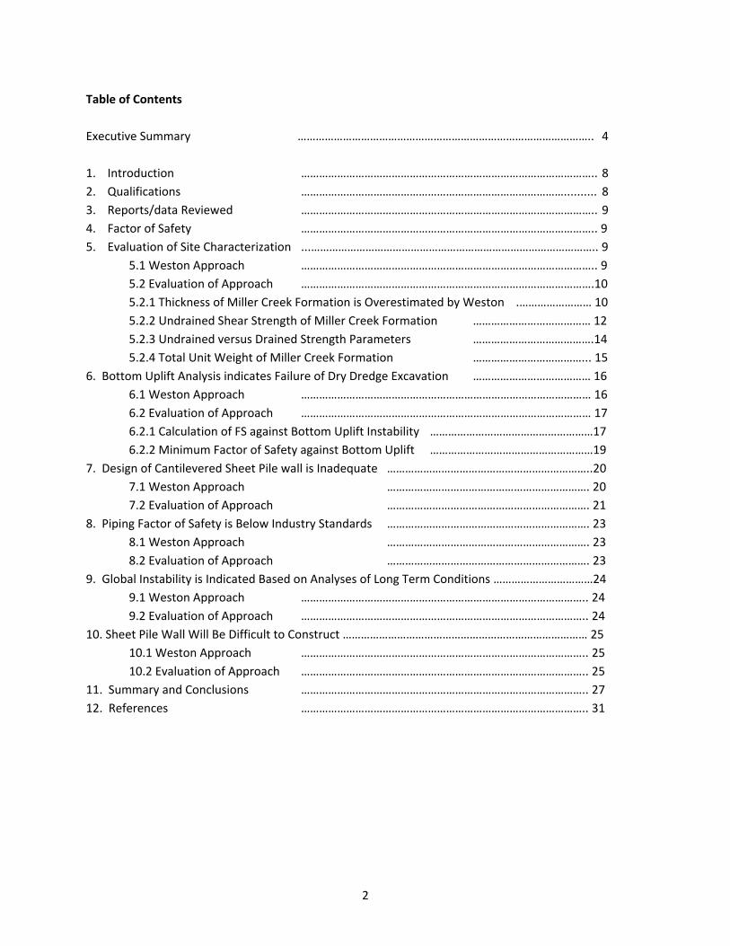
Table of Contents
Executive Summary …………………………………………………………………………………….. 4
1. Introduction …………………………………………………………………………………….. 8
2. Qualifications …………………………………………………………………………….......... 8
3. Reports/data Reviewed …………………………………………………………………………………….. 9
4. Factor of Safety …………………………………………………………………………………….. 9
5. Evaluation of Site Characterization ...………………………………………………………………………………….. 9
5.1 Weston Approach …………………………………………………………………………………….. 9
5.2 Evaluation of Approach …………………………………………………………………………………….10
5.2.1 Thickness of Miller Creek Formation is Overestimated by Weston .…………………… 10
5.2.2 Undrained Shear Strength of Miller Creek Formation ………………………………… 12
5.2.3 Undrained versus Drained Strength Parameters ………………………………….14
5.2.4 Total Unit Weight of Miller Creek Formation ………………………………... 15
6. Bottom Uplift Analysis indicates Failure of Dry Dredge Excavation ………………………………… 16
6.1 Weston Approach …………………………………………………………………………………… 16
6.2 Evaluation of Approach …………………………………………………………………………………… 17
6.2.1 Calculation of FS against Bottom Uplift Instability ………………………………………………17
6.2.2 Minimum Factor of Safety against Bottom Uplift ………………………………………………19
7. Design of Cantilevered Sheet Pile wall is Inadequate …………………………………………………………..20
7.1 Weston Approach …………………………………………………………. 20
7.2 Evaluation of Approach …………………………………………………………. 21
8. Piping Factor of Safety is Below Industry Standards …………………………………………………………. 23
8.1 Weston Approach …………………………………………………………. 23
8.2 Evaluation of Approach …………………………………………………………. 23
9. Global Instability is Indicated Based on Analyses of Long Term Conditions ……………………………24
9.1 Weston Approach ………………………………………………………………………………….. 24
9.2 Evaluation of Approach ………………………………………………………………………………….. 24
10. Sheet Pile Wall Will Be Difficult to Construct ……………………………………………………………………… 25
10.1 Weston Approach ………………………………………………………………………………….. 25
10.2 Evaluation of Approach ………………………………………………………………………………….. 25
11. Summary and Conclusions ………………………………………………………………………………….. 27
12. References ………………………………………………………………………………….. 31
3
List of Tables
Table 1. Types and Number of Tests used by Weston to Determine SU of Miller Creek Formation at AQ‐
SB‐02
Table 2. Comparison of Measured and Correlated Unit Weights
Table 3. Summary of Bottom Instability Calculations
List of Figures
Figure 1. Stratigraphy at AQ‐SB‐02
Figure 2. Percent Clay Based on Particle Size Distributions of SC Layer: AQ‐SB‐02
Figure 3. Penetration Test Correlations (Kulhawy and Mayne 1990)
Figure 4. Undrained Shear Strength Variation at AQ‐SB‐02
Figure 5. Measured and Correlated Unit Weights
Figure 6. Geometry at Islais Creek Excavation (Koutsoftas 2012)
Figure 7. Undrained Shear Strength of San Francisco Bay Mud (Koutsoftas 2012)
Figure 8. P‐y Curves for Stiff Clays in the Presence of Water (Reese et al., 1975)
Figure 9. P‐y Curve for Stiff Clay with no Free Water (Reese et al., 1975)
Figure 10. P‐y Curve of Silt (Reese and Van Impe, 2001)
Appendix. Curriculum Vitae of Richard Finno
4
Executive Summary
This report presents my evaluation of the geotechnical aspects of the Weston final technical submittal
based on reports and data listed in Section 3 and includes my evaluation of the five essential
geotechnical analyses presented by Weston. This work supplements my report dated October 27, 2014,
and as such, summarizes my evaluation of the geotechnical conditions at the Ashland/Northern States
Power Lakefront Superfund Site (the Site) and their impact on the proposed dry dredge scheme. I
understand that the dry dredge scheme will entail driving a row of sheet piles across the bay and around
the shore line to provide an impervious wall. The scheme proposed in the Weston’s final technical
submittal calls for breaking up the dry dredge area into a number of smaller cells comprised of sheet pile
walls. Water will be pumped from the cells, the contaminated sediments subsequently will be
excavated, backfill placed and sheet piles extracted.
After reviewing the data and analyses presented in the Weston final technical submittal, I have reached
the following conclusions:
The excavation in a dry dredge scheme will not be stable because bottom heave due to artesian
water pressures will likely occur at some locations after soil has been excavated. Contrary to
Weston’s opinion, when bottom heave occurs, the excavation likely will be flooded by ground
water from the underlying Copper Falls aquifer.
The Factors of Safety (FS) used in Weston’s analyses do not appropriately account for variability
in Site subsurface conditions, engineering parameters and loading condition. The FS should
reflect uncertainties in subsurface conditions, engineering parameters, loading conditions and
consequences of failure. The FS used by Weston did not adequately consider these factors in all
cases, particularly when considering the potential for bottom heave from the artesian pressures
in the Copper Falls aquifer.
Weston identified the subsurface conditions at boring AQ‐SB‐02 as the most critical for bottom
heave due to artesian pressures and concluded that the factor of safety for the entire
excavation based on these conditions was adequate based on assuming that the shear strength
of the Miller Creek Formation at the edges of the excavation between the bottom of the
excavation and the top of the Copper Falls Formation could be counted upon to resist the uplift
forces. They also presented an analysis that purported to show the silty sand/clayey sand layer
could be considered as part of the Miller Creek Formation aquiclude and would also resist the
uplift forces. Their analysis is incorrect for the following reasons:
o Stratigraphy defined by soundings CPT‐4 and borings SB‐163, SB‐182 and SB‐183 and SB‐
185 have lower FS against bottom heave due to artesian pressures than does AQ‐SB‐02.
The conditions at these locations, and those at CPT‐5, SB‐162, SB‐164 and SB‐181 have
FS against bottom heave is less than 1 at each location.
5
o The Weston dominant clay fraction analysis based on a method proposed by Mitchell
(1976) is incorrect. Weston incorrectly defined the amount of clay sized particles from
the particle size distributions for samples obtained from the silty/ clayey sand layer in
boring AQ‐SB‐02. When the proper amount of clay sized particles are employed in the
Weston analysis, the analyses shows that there is insufficient clay content for the clay to
dominate the behavior of the silty/sandy clay layer. Their conclusion that this layer can
be considered to have low permeability and thus be part of the Miller Creek Formation
aquiclude is incorrect. This makes the aquiclude that resists uplift from the artesian
pressure 8.15 ft thinner at the AQ‐SB‐02 location than assumed by Weston.
o Weston assumes the shear strength of parts of the Miller Creek Formation can be relied
upon to resist uplift from the artesian pressures, and as justification, cite a work by
Koutsoftas (2012). However the geometry of the excavation they cite is only 36 ft wide
and is very long relative to its width. Koutsoftas considers the uplift conditions as plane
strain and does not consider the shear strength at the ends of the excavation when
computing FS against uplift.
o Weston only presents an uplift calculation that considers the entire dry dredge area,
and relies upon the shear resistance of the Miller Creek Formation at the edges of the
excavation between the bottom of the excavation and the top of the Copper Falls
Formation, including the silty/clayey sand layer mischaracterized as low permeability
soil. The width of the entire excavation is 200 ft and its length approximately 1600 ft.
Following Weston’s own reference, the Koutsoftas approach would model this as a
plane strain condition and make the calculation per ft of sheet pile wall length. This
approach yields a FS of 0.99, less that the value of 1.44 computed by Weston for the
same conditions.
o The analysis of bottom heave at the AQ‐SB‐02 location due to artesian water pressures
in the Copper Falls aquifer based on the correct approach indicates that an uplift failure
will occur. The computed values of FS at this location and at SB‐185 for various
assumptions regarding interface shear strength are lower than those reported by
Weston, and all are less than acceptable value of 1.5 (and most are less than 1 indicating
that an uplift failure would occur).
The dry excavation scheme, even with a cell by cell approach with minimum widths of 100 ft, is
not safe with respect to bottom heave caused by the artesian pressures in the Copper Falls
aquifer, even if one accepts the minimum acceptable value of FS of 1.25 that Weston espoused.
6
Even without considering the additional water flow around the sheet pile wall, the FS against
piping due to upward flow at the location of CPT‐05 is 2.5 and less than industry standard of 4 to
5. Note that Weston changed the acceptable FS from 4 to 5 in their 2009 report to 2 in their
2014 report. They did so without comment. Weston in their conceptual design stated that this
minimum FS should be between 4 and 5, and I agree. If piping were to occur due to upward
flow along the sheet pile, then the sheet pile wall would collapse as a result of the removal of
the soil against its toe, leading to flooding of the excavation.
Weston’s design did not consider a global instability failure mode that encompasses the entire
sheet pile wall and passes through the underlying Copper Falls Formation. The FS against this
global instability may be computed assuming a sliding block model when the excavation is at
final depth. Given that the dry dredge excavation will last more than 1 construction season,
appreciable dissipation of excess pore water pressures will occur, especially in the ML strata in
the Miller Creek Formation. Therefore, it is standard practice to consider both short (undrained)
and long (drained) term conditions for this potential failure mode. Failure in terms of a global
instability is a possibility for the long term conditions for the dry dredge option, and is another
indication of the unsuitability of the dry dredge option. Failure in this case implies that a mass
of soil encompassing the wall will slide into the excavation and subsequently flooding it.
Weston’s design of the sheet pile wall was inadequate in that it did not adequately account for
expected loading conditions. While they included the effects of wave loadings such that the top
of the sheet piles will be at elevation 622 ft, their design did not consider the effects of cyclic
loading on the shear strength of the Miller Creek formation silts and clays. Cyclically applied
lateral loads have the effect of significantly reducing the resistance of the soil near the ground
surface, such that use of monotonically defined shear strengths are inappropriate. Sheet pile
walls installed on shore normally are not designed to resist cyclic lateral loads such as those
induced by waves, but guidance can be found by looking at the large body of literature on piles
subjected to cyclic lateral loads.
Weston’s design of the sheet pile wall was inadequate in that it did not account for
development of water filled gaps during period of high water and cyclic loadings, or the
directional effects of wave loadings. Sheet pile wall will provide resistance to bending and
tensile stresses, but not compressive stresses. Therefore, when the wall has a 90 degree bend,
some bracing will be required to ensure stability. Furthermore, Weston provided no details
regarding how the movements of the sheet pile wall were computed, a critical factor in
determining if the wall will be overtopped during a storm resulting in flooding of the excavation.
7
Weston’s design of the sheet pile wall results in a sheet pile wall that will not be able to be
constructed such that it will perform as intended. Weston acknowledged that there will be
leakage through the sheet pile wall, but does not specifically address the quantity of leakage,
other that it would be reduced by using a cell by cell approach. The quantity of leakage,
especially given the potential of losing sheet pile interlocks when gravel and/or when hard
driving conditions are encountered at some locations, has a major impact on whether or not a
sheet pile wall would perform as it was designed.
There also are a number of significant construction‐related difficulties associated with the dry
dredge option not addressed in their report. It will be very difficult to construct the sheet pile
wall and maintain its function as an “impervious” barrier as well as its structural integrity. It will
be difficult to install sheeting to required depth through the hard portions of the glacial tills. Till
refers to any soil that is deposited from a glacier and thus includes soils deposited in many ways.
Significant variations in its composition should be expected within the Site, given its size.
Concentrated flows of water through the sheeting could develop as a result of losing the
sheeting interlocks when driving in tills with gravel and boulders, which would lead to a collapse
of the sheet pile wall and subsequent flooding of the excavation.
For these reasons, and as detailed in the body of the report, it is my opinion that the proposed dry
dredge scheme is not safe or implementable at the Site, because of the potential for bottom heave,
global instability and various design and/or constructability concerns discussed herein. A wet dredge
approach would eliminate these risks, and is thus a far better solution to the geotechnical challenges of
the project.
8
1. Introduction
This report provides an Independent evaluation from a geotechnical perspective of the proposed “dry
dredge” option for removal of contaminated sediments. The Record of Decision contemplates the
installation of a cantilevered sheet pile wall across the bay to form an “impervious” barrier. The wall will
contain several 90 degree bends as it traverses the bay. Water inside the sheets will be pumped in an
attempt to create a dry surface to allow contaminated sediment to be excavated with conventional
earth moving equipment. Sediment will be removed to nominal elevation 590 ft, and thus will create a
cantilevered wall with an unsupported height of about 13 ft.
Weston prepared a preliminary report and concluded this approach was technically feasible based on
the subsurface information available to them at the time. They prepared a second report based on
additional subsurface information and again concluded that the “dry dredge” option was technically
feasible. However, they proposed in this second report to break the large dry dredge area into a
number of smaller cells comprised of sheet pile walls.
This report presents my evaluation of the geotechnical aspects of the Weston final technical submittal
based on reports and data listed in Section 3 and includes my evaluation of the five essential
geotechnical analyses presented by Weston. This report supplements my report dated October 27,
2014 (Finno 2014).
2. Qualifications
I am a Professor of Civil Engineering specializing in geotechnical engineering with 35 years of experience
in the field. I received a BS in Civil Engineering from the University of Illinois at Urbana‐Champaign in
1975, a MSCE in Geotechnical Engineering from Stanford University in 1976 and a PhD in Civil
Engineering from Stanford University in 1983. I have taught at Northwestern University since 1986. I
have conducted research with competitively‐secured grants of more than $8 million in the areas of full‐
scale performance of deep excavations and tunnels, adaptive management methods in geotechnical
engineering, numerical analysis, inverse analysis techniques, failure processes in soil, small strain
behavior of clays and non‐destructive testing of deep foundations. These funds include a grant of more
than $2 million from the National Science Foundation for research concerning predicting, monitoring
and controlling ground movements caused by supported excavations. I have pioneered the use of
adaptive management techniques to predict, monitor and control ground movements caused by deep
excavations. I have authored or co‐authored 150 reviewed technical papers and 20 technical reports.
Of the technical papers, excavation support is the subject of 54 of them. My work has resulted in
recognition in the form eight major awards from the American Society of Civil Engineers (ASCE),
including the Karl Terzaghi Award, considered by many as the most prestigious award for a geotechnical
engineer in the US, and the Harry Schnabel Jr. Award for Career Excellence in Earth Retaining
Structures. I have served as Chair of the Earth Retaining Structures Committee of ASCE and as an Editor
of the Journal of Geotechnical and Geoenvironmental Engineering of ASCE. I have consulted for many
9
organizations, including the US EPA when I provided scientific peer review for standards 40 CFR PART
503.
3. Reports reviewed
In addition to the materials listed in my October 27, 2014 report (Finno 2014), I have reviewed the
following materials in connection with my evaluation:
a) Weston Solutions, Inc. (2014). “Final Ashland Lakefront Superfund Site Technical
Memorandum,” prepared for: US Environmental Protection Agency by Weston Solutions, Inc.,
Dr. William L. Deutsch Jr., PhD, PE, Geotechnical Consulting Engineer and Adam Brown, PE,
Principal Project Engineer, US EPA Contract No. EP‐S5‐06‐04, Work Assignment No.:S05‐008‐
0711‐019S September 2014 (hereafter referred to as Final Report).
b) Schulenberg, J.W. (2014). Peer review Concerning Dry Excavation Site Name: Ashland/NSP
Lakefront Sit: Ashland Wisconsin EPA Site ID #: WISFN0507952 State: Wisconsin, 21 Feb 2014.
c) Schulenberg, J.W. (2014a). Letter report to Sumona N. Majumdar dated September 23, 2014.
4. Factor of Safety
The Factor of Safety (FS) is commonly defined as the resistance of a system divided by the applied load.
An acceptable FS is a value to which a structure must conform or exceed. The FS in geotechnical
engineering depends on many factors, including type and importance of a structure or geostructure, the
soil stratigraphy and its variability, the thoroughness of the site investigation, the expected level and
method of construction inspection and quality control and the consequences of failure. Appropriate
values in geotechnical engineering also depend on the mode of failure being considered.
A more complete description of the factors of safety applicable to the Ashland Superfund Site was
included in my 2014 report (Finno 2014) and will not be repeated herein. Specific comments regarding
FS employed by Weston in their 2014 report will be made in the relevant sections that follow.
5. Evaluation of Site Characterization
The development of the design subsurface condition is key to all subsequent analyses.
5.1 Weston approach
Weston selected two offshore and one onshore locations to represent the subsurface conditions that
were most critical with regards to the stability of the dry dredge excavation. They accepted the Anchor
QEA report conclusion that the subsurface conditions at boring AQ‐SB‐02 has the highest potential for
bottom uplift while that at AQ‐SB‐04 had the highest potential for basal heave, and performed analyses
for subsurface cross sections developed from the subsurface data measured at both of those borings.
10
They presented their interpretation of a design subsurface cross section and estimated undrained shear
strength within the Miller Creek Formation at each of the locations in Appendices A and B of Exhibit 2 of
their final report. They also selected the on shore boring SB‐185 as being the critical conditions on
shore, based on Anchor QEA results of bottom uplift calculations that showed the FS against uplift was
0.95 to 1.0. Weston presented their interpretation of the design subsurface cross section at this
location and estimated undrained shear strength within the Miller Creek Formation in Appendix A of
Exhibit 9 of their final report.
At each of the locations, Weston divided the Miller Creek Formation into layers based on soil description
and penetration test blow count (N value). For each layer they determined the average undrained shear
strength based on results of available test data for the particular stratum. While not available for each
layer, these tests included pocket penetrometer and torvane tests made in the field on samples
collected by either split spoon or 3 inch diameter tubes, laboratory unconsolidated undrained (UU)
triaxial and unconfined compression (U) tests, and correlations with individual SPT N values. Weston
discarded excessively high values before averaging the results of whatever tests were available for each
sublayer.
Weston used correlations between N values and undrained shear strength from Terzaghi and Peck
(1967) and Sowers (1979). They further differentiated the silts and clays for these correlations as
functions of “low,” “medium” or “high” plasticity. The correlation they used depended on these
descriptors such that. Su = 75N, 150 N or 250 N, for “low,” “medium” and “high” plasticity, respectively,
with N expressed in blows per foot and Su expressed as psf.
Weston determined the unit weight based on correlations with SPT N values via a table of values
“adapted from DM7.1.” These correlations were used except unit weight when unit weight was
measured directly in samples from Shelby tubes used for UU or U tests.
5.2 Evaluation of approach
This report will focus on the stratigraphy at boring AQ‐SB‐02 which Weston identified as being the most
critical conditions for bottom uplift instability. However, their approach for defining stratigraphy and
engineering parameters for each stratum was the same for each of the three sections they presented in
their report. They included no discussion about uncertainties in neither the stratigraphy nor associated
parameters and the effects of the uncertainties on acceptable values of FS. Comments will be made in
the following sections regarding these issues when appropriate.
5.2.1 Thickness of Miller Creek Formation is Overestimated by Weston
One of the main assumptions in Weston’s interpretation of interpretation of AQ‐SB‐02 and the on shore
SB 185 is the inclusion of the silty/clayey sand layer between the Miller Creek Formation clays and the
Copper Falls aquifer as a relatively impervious layer that is part of the Miller Creek aquitard.
11
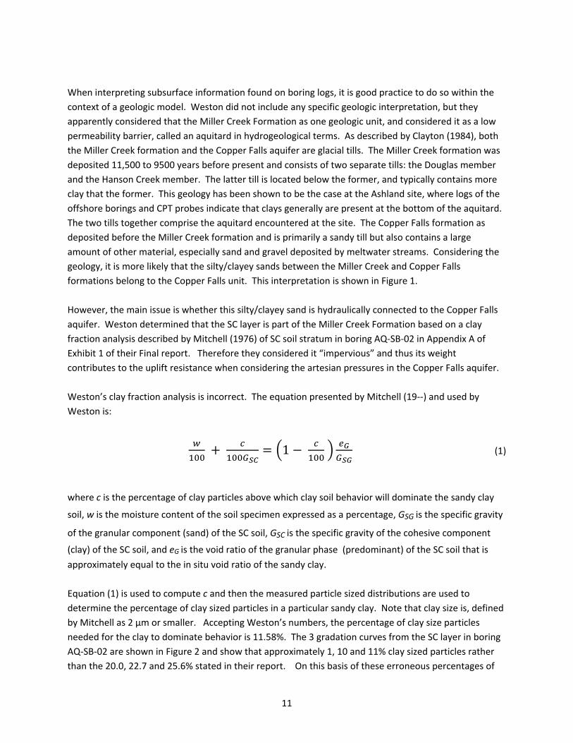
When interpreting subsurface information found on boring logs, it is good practice to do so within the
context of a geologic model. Weston did not include any specific geologic interpretation, but they
apparently considered that the Miller Creek Formation as one geologic unit, and considered it as a low
permeability barrier, called an aquitard in hydrogeological terms. As described by Clayton (1984), both
the Miller Creek formation and the Copper Falls aquifer are glacial tills. The Miller Creek formation was
deposited 11,500 to 9500 years before present and consists of two separate tills: the Douglas member
and the Hanson Creek member. The latter till is located below the former, and typically contains more
clay that the former. This geology has been shown to be the case at the Ashland site, where logs of the
offshore borings and CPT probes indicate that clays generally are present at the bottom of the aquitard.
The two tills together comprise the aquitard encountered at the site. The Copper Falls formation as
deposited before the Miller Creek formation and is primarily a sandy till but also contains a large
amount of other material, especially sand and gravel deposited by meltwater streams. Considering the
geology, it is more likely that the silty/clayey sands between the Miller Creek and Copper Falls
formations belong to the Copper Falls unit. This interpretation is shown in Figure 1.
However, the main issue is whether this silty/clayey sand is hydraulically connected to the Copper Falls
aquifer. Weston determined that the SC layer is part of the Miller Creek Formation based on a clay
fraction analysis described by Mitchell (1976) of SC soil stratum in boring AQ‐SB‐02 in Appendix A of
Exhibit 1 of their Final report. Therefore they considered it “impervious” and thus its weight
contributes to the uplift resistance when considering the artesian pressures in the Copper Falls aquifer.
Weston’s clay fraction analysis is incorrect. The equation presented by Mitchell (19‐‐) and used by
Weston is:
1 (1)
where c is the percentage of clay particles above which clay soil behavior will dominate the sandy clay
soil, w is the moisture content of the soil specimen expressed as a percentage, GSG is the specific gravity
of the granular component (sand) of the SC soil, GSC is the specific gravity of the cohesive component
(clay) of the SC soil, and eG is the void ratio of the granular phase (predominant) of the SC soil that is
approximately equal to the in situ void ratio of the sandy clay.
Equation (1) is used to compute c and then the measured particle sized distributions are used to
determine the percentage of clay sized particles in a particular sandy clay. Note that clay size is, defined
by Mitchell as 2 μm or smaller. Accepting Weston’s numbers, the percentage of clay size particles
needed for the clay to dominate behavior is 11.58%. The 3 gradation curves from the SC layer in boring
AQ‐SB‐02 are shown in Figure 2 and show that approximately 1, 10 and 11% clay sized particles rather
than the 20.0, 22.7 and 25.6% stated in their report. On this basis of these erroneous percentages of
12
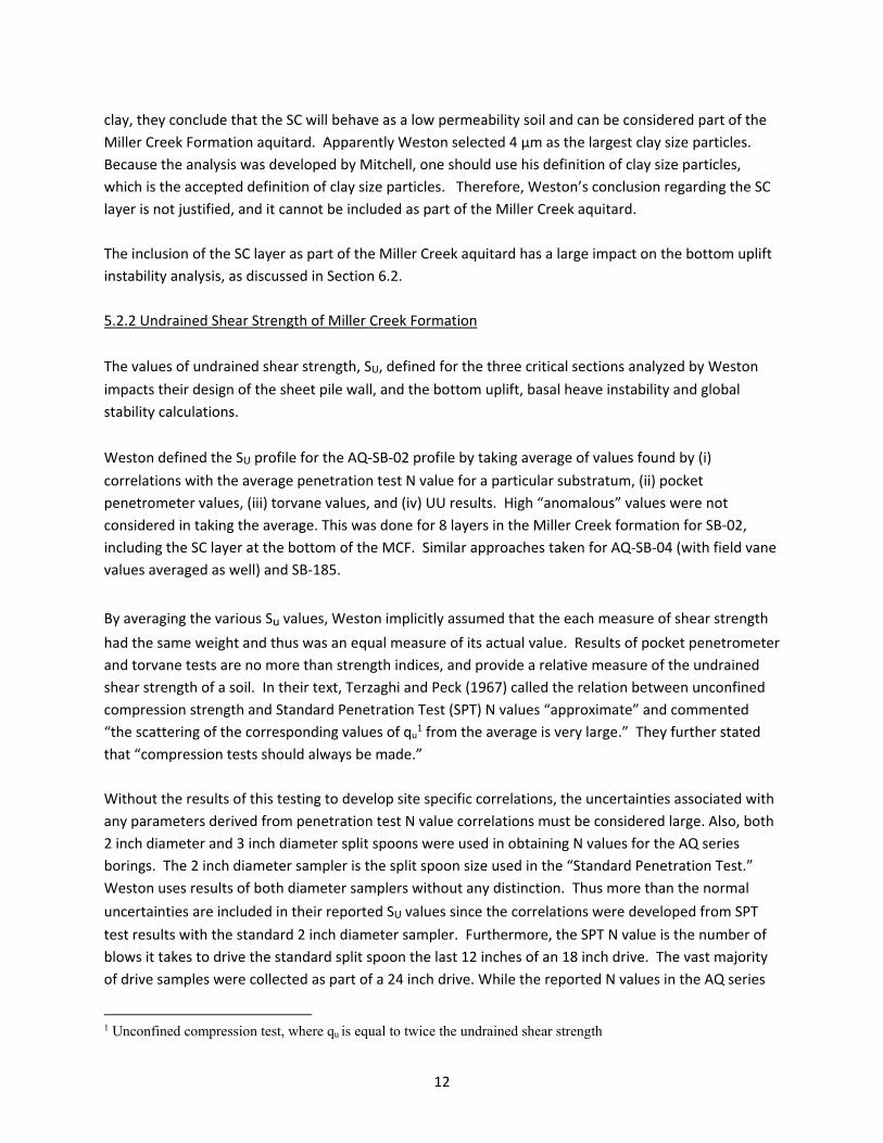
clay, they conclude that the SC will behave as a low permeability soil and can be considered part of the
Miller Creek Formation aquitard. Apparently Weston selected 4 μm as the largest clay size particles.
Because the analysis was developed by Mitchell, one should use his definition of clay size particles,
which is the accepted definition of clay size particles. Therefore, Weston’s conclusion regarding the SC
layer is not justified, and it cannot be included as part of the Miller Creek aquitard.
The inclusion of the SC layer as part of the Miller Creek aquitard has a large impact on the bottom uplift
instability analysis, as discussed in Section 6.2.
5.2.2 Undrained Shear Strength of Miller Creek Formation
The values of undrained shear strength, SU, defined for the three critical sections analyzed by Weston
impacts their design of the sheet pile wall, and the bottom uplift, basal heave instability and global
stability calculations.
Weston defined the SU profile for the AQ‐SB‐02 profile by taking average of values found by (i)
correlations with the average penetration test N value for a particular substratum, (ii) pocket
penetrometer values, (iii) torvane values, and (iv) UU results. High “anomalous” values were not
considered in taking the average. This was done for 8 layers in the Miller Creek formation for SB‐02,
including the SC layer at the bottom of the MCF. Similar approaches taken for AQ‐SB‐04 (with field vane
values averaged as well) and SB‐185.
By averaging the various Su values, Weston implicitly assumed that the each measure of shear strength
had the same weight and thus was an equal measure of its actual value. Results of pocket penetrometer
and torvane tests are no more than strength indices, and provide a relative measure of the undrained
shear strength of a soil. In their text, Terzaghi and Peck (1967) called the relation between unconfined
compression strength and Standard Penetration Test (SPT) N values “approximate” and commented
“the scattering of the corresponding values of qu1 from the average is very large.” They further stated
that “compression tests should always be made.”
Without the results of this testing to develop site specific correlations, the uncertainties associated with
any parameters derived from penetration test N value correlations must be considered large. Also, both
2 inch diameter and 3 inch diameter split spoons were used in obtaining N values for the AQ series
borings. The 2 inch diameter sampler is the split spoon size used in the “Standard Penetration Test.”
Weston uses results of both diameter samplers without any distinction. Thus more than the normal
uncertainties are included in their reported SU values since the correlations were developed from SPT
test results with the standard 2 inch diameter sampler. Furthermore, the SPT N value is the number of
blows it takes to drive the standard split spoon the last 12 inches of an 18 inch drive. The vast majority
of drive samples were collected as part of a 24 inch drive. While the reported N values in the AQ series
1 Unconfined compression test, where qu is equal to twice the undrained shear strength
13
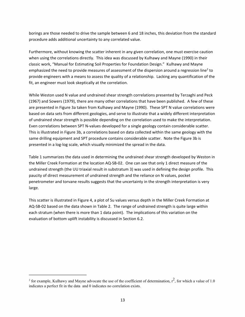
borings are those needed to drive the sample between 6 and 18 inches, this deviation from the standard
procedure adds additional uncertainty to any correlated value.
Furthermore, without knowing the scatter inherent in any given correlation, one must exercise caution
when using the correlations directly. This idea was discussed by Kulhawy and Mayne (1990) in their
classic work, “Manual for Estimating Soil Properties for Foundation Design.” Kulhawy and Mayne
emphasized the need to provide measures of assessment of the dispersion around a regression line2 to
provide engineers with a means to assess the quality of a relationship. Lacking any quantification of the
fit, an engineer must look skeptically at the correlation.
While Weston used N value and undrained shear strength correlations presented by Terzaghi and Peck
(1967) and Sowers (1979), there are many other correlations that have been published. A few of these
are presented in Figure 3a taken from Kulhawy and Mayne (1990). These SPT N value correlations were
based on data sets from different geologies, and serve to illustrate that a widely different interpretation
of undrained shear strength is possible depending on the correlation used to make the interpretation.
Even correlations between SPT N‐values developed for a single geology contain considerable scatter.
This is illustrated in Figure 3b, a correlations based on data collected within the same geology with the
same drilling equipment and SPT procedure contains considerable scatter. Note the Figure 3b is
presented in a log‐log scale, which visually minimized the spread in the data.
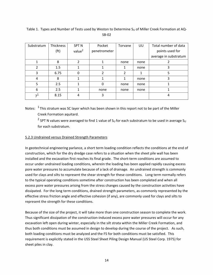
Table 1 summarizes the data used in determining the undrained shear strength developed by Weston in
the Miller Creek Formation at the location AQ‐SB‐02. One can see that only 1 direct measure of the
undrained strength (the UU triaxial result in substratum 3) was used in defining the design profile. This
paucity of direct measurement of undrained strength and the reliance on N values, pocket
penetrometer and torvane results suggests that the uncertainty in the strength interpretation is very
large.
This scatter is illustrated in Figure 4, a plot of Su values versus depth in the Miller Creek Formation at
AQ‐SB‐02 based on the data shown in Table 2. The range of undrained strength is quite large within
each stratum (when there is more than 1 data point). The implications of this variation on the
evaluation of bottom uplift instability is discussed in Section 6.2.
2 for example, Kulhawy and Mayne advocate the use of the coefficient of determination, r2, for which a value of 1.0 indicates a perfect fit in the data and 0 indicates no correlation exists.
14
Table 1. Types and Number of Tests used by Weston to Determine SU of Miller Creek Formation at AQ‐
SB‐02
Substratum Thickness
(ft)
SPT N
value2 Pocket
penetrometer
Torvane UU Total number of data
points used for
average in substratum
1 8 2 1 none none 2
2 1.5 1 1 1 none 3
3 6.75 0 2 2 1 5
4 8 1 1 1 none 3
5 2.5 1 0 none none 1
6 2.5 1 none none none 1
71 8.15 4 3 4
Notes: 1 This stratum was SC layer which has been shown in this report not to be part of the Miller
Creek Formation aquitard.
2 SPT N values were averaged to find 1 value of SU for each substratum to be used in average SU
for each substratum.
5.2.3 Undrained versus Drained Strength Parameters
In geotechnical engineering parlance, a short term loading condition reflects the conditions at the end of
construction, which for the dry dredge case refers to a situation when the sheet pile wall has been
installed and the excavation first reaches its final grade. The short‐term conditions are assumed to
occur under undrained loading conditions, wherein the loading has been applied rapidly causing excess
pore water pressures to accumulate because of a lack of drainage. An undrained strength is commonly
used for clays and silts to represent the shear strength for these conditions. Long term normally refers
to the typical operating conditions sometime after construction has been completed and when all
excess pore water pressures arising from the stress changes caused by the construction activities have
dissipated. For the long term conditions, drained strength parameters, as commonly represented by the
effective stress friction angle and effective cohesion (if any), are commonly used for clays and silts to
represent the strength for these conditions.
Because of the size of the project, it will take more than one construction season to complete the work.
Thus significant dissipation of the construction‐induced excess pore water pressures will occur for any
excavation left open during winter, especially in the silt strata within the Miller Creek Formation, and
thus both conditions must be assumed in design to develop during the course of the project. As such,
both loading conditions must be analyzed and the FS for both conditions must be satisfied. This
requirement is explicitly stated in the USS Steel Sheet Piling Design Manual (US Steel Corp. 1975) for
sheet piles in clay.
15
With the exception of using drained strength parameters when computing lateral earth pressures on the
active side of the sheet pile wall, Weston is silent on the issue of drained strength parameters and long
term analyses.
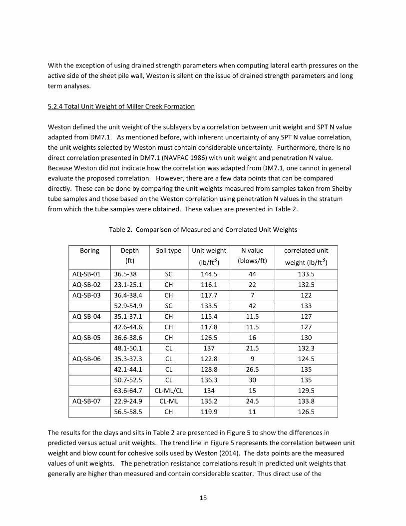
5.2.4 Total Unit Weight of Miller Creek Formation
Weston defined the unit weight of the sublayers by a correlation between unit weight and SPT N value
adapted from DM7.1. As mentioned before, with inherent uncertainty of any SPT N value correlation,
the unit weights selected by Weston must contain considerable uncertainty. Furthermore, there is no
direct correlation presented in DM7.1 (NAVFAC 1986) with unit weight and penetration N value.
Because Weston did not indicate how the correlation was adapted from DM7.1, one cannot in general
evaluate the proposed correlation. However, there are a few data points that can be compared
directly. These can be done by comparing the unit weights measured from samples taken from Shelby
tube samples and those based on the Weston correlation using penetration N values in the stratum
from which the tube samples were obtained. These values are presented in Table 2.
Table 2. Comparison of Measured and Correlated Unit Weights
Boring Depth
(ft)
Soil type Unit weight
(lb/ft3)
N value
(blows/ft)
correlated unit
weight (lb/ft3)
AQ‐SB‐01 36.5‐38 SC 144.5 44 133.5
AQ‐SB‐02 23.1‐25.1 CH 116.1 22 132.5
AQ‐SB‐03 36.4‐38.4 CH 117.7 7 122
52.9‐54.9 SC 133.5 42 133
AQ‐SB‐04 35.1‐37.1 CH 115.4 11.5 127
42.6‐44.6 CH 117.8 11.5 127
AQ‐SB‐05 36.6‐38.6 CH 126.5 16 130
48.1‐50.1 CL 137 21.5 132.3
AQ‐SB‐06 35.3‐37.3 CL 122.8 9 124.5
42.1‐44.1 CL 128.8 26.5 135
50.7‐52.5 CL 136.3 30 135
63.6‐64.7 CL‐ML/CL 134 15 129.5
AQ‐SB‐07 22.9‐24.9 CL‐ML 135.2 24.5 133.8
56.5‐58.5 CH 119.9 11 126.5
The results for the clays and silts in Table 2 are presented in Figure 5 to show the differences in
predicted versus actual unit weights. The trend line in Figure 5 represents the correlation between unit
weight and blow count for cohesive soils used by Weston (2014). The data points are the measured
values of unit weights. The penetration resistance correlations result in predicted unit weights that
generally are higher than measured and contain considerable scatter. Thus direct use of the
16
correlations introduce uncertainties into any calculation that depends on the total unit weights of the
soils. This will be discussed further in Section 6.2 with respect to bottom uplift potential.
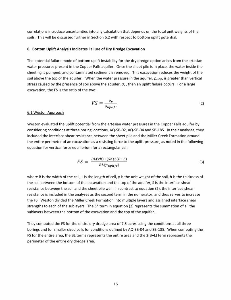
6. Bottom Uplift Analysis Indicates Failure of Dry Dredge Excavation
The potential failure mode of bottom uplift instability for the dry dredge option arises from the artesian
water pressures present in the Copper Falls aquifer. Once the sheet pile is in place, the water inside the
sheeting is pumped, and contaminated sediment is removed. This excavation reduces the weight of the
soil above the top of the aquifer. When the water pressure in the aquifer, puplift, is greater than vertical
stress caused by the presence of soil above the aquifer, σv , then an uplift failure occurs. For a large
excavation, the FS is the ratio of the two:
(2)
6.1 Weston Approach
Weston evaluated the uplift potential from the artesian water pressures in the Copper Falls aquifer by
considering conditions at three boring locations, AQ‐SB‐02, AQ‐SB‐04 and SB‐185. In their analyses, they
included the interface shear resistance between the sheet pile and the Miller Creek Formation around
the entire perimeter of an excavation as a resisting force to the uplift pressure, as noted in the following
equation for vertical force equilibrium for a rectangular cell:
(3)
where B is the width of the cell, L is the length of cell, γ is the unit weight of the soil, h is the thickness of
the soil between the bottom of the excavation and the top of the aquifer, S is the interface shear
resistance between the soil and the sheet pile wall. In contrast to equation (2), the interface shear
resistance is included in the analyses as the second term in the numerator, and thus serves to increase
the FS. Weston divided the Miller Creek Formation into multiple layers and assigned interface shear
strengths to each of the sublayers. The Sh term in equation (2) represents the summation of all the
sublayers between the bottom of the excavation and the top of the aquifer.
They computed the FS for the entire dry dredge area of 7.5 acres using the conditions at all three
borings and for smaller sized cells for conditions defined by AQ‐SB‐04 and SB‐185. When computing the
FS for the entire area, the BL terms represents the entire area and the 2(B+L) term represents the
perimeter of the entire dry dredge area.
17
6.2 Evaluation of Approach
Weston made two assumptions in their analyses that are not justified. They assumed that (i) the
thickness of the Miller Creek aquiclude at location AQ‐SB‐02 included the clayey sand layer observed at
the top of Copper Falls aquifer and (ii) that the interface shear strength provides uplift resistance around
the entire perimeter of the excavation. While not explicitly stated in their report, the same logic was
used when selecting the elevation of the bottom of the aquitard at SB‐185.
As discussed before in Section 5.2.1, including the clayey sand layer as part of the aquitard is not
justified by the Mitchell analyses. This clayey sand layer is 8.2 ft thick at AQ‐SB‐02 and Weston’s
inclusion of it as part of the aquitard thickness makes a large difference in the computed FS. Weston
also included 1.7 ft of silty and clayey sand in the aquitard thickness at SB‐185.
6.2.1 Calculation of FS against Bottom Uplift Instability
Weston justified the use of including the shearing resistance in equation (3) by referring to a paper by
Koutsoftas (2012). In it, Koutsoftas was describing the potential for bottom instability caused by uplift
pressures in granular soils underlying a soft clay bottom for Contract D of the Islais Creek excavation in
San Francisco. This excavation was for a transit line and had a width of 11 m, as shown in Figure 6a
taken from Koutsoftas (2102). Because the Islais Creek excavation was long relative to its width,
Koutsoftas analyzed the uplift potential by assuming plane strain conditions. He did not include the
entire perimeter of the excavation when including the interface shearing as part of the resistance to the
uplift pressures. Weston presented essentially the same figure in their bottom uplift technical
discussion; it is reproduced in Figure 6b. The difference between the two figures is that Weston
provided no dimension for B, presumably implying that the approach was valid for any width B. They
used the Islais Creek case to justify using the interface shear resistance around the perimeter for any
sized excavation as a resistance to uplift. However, Koutsoftas clearly considered plane strain
conditions and only included interface shearing resistance at the ends of the smaller dimension of the
excavation. Under these conditions the analysis is made on a per ft of wall length basis; in other words,
the condition at the ends of the wall at the wider side of the excavation do not affect conditions in the
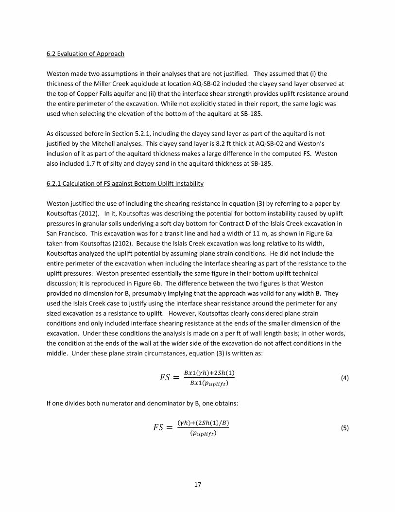
middle. Under these plane strain circumstances, equation (3) is written as:
(4)
If one divides both numerator and denominator by B, one obtains:
/
(5)
18
As one can see from equation (5), as the width of the excavation B gets larger, the relative contribution
of the interface shear (the second term in the numerator) gets smaller and the computed FS approaches
that compute by eq. (2). Similar observations can be made seen if one considers interface shear
resistance along the entire perimeter, as Weston did in their calculations. In this case one divides the
numerator and denominator in eq. (3) by BL to obtain:
/
( 6)
Again, the second term in the numerator gets smaller as the area of the excavation increases. This is
why for large excavations the shearing resistance at the soil‐sheet pile wall interface generally is
neglected. When computing FS for the entire dry dredge area with its irregular shape, its constant width
of 200 ft and a length of approximately 1600 ft, the plane strain assumption is applicable. It is extremely
difficult to envision any failure mechanism wherein a 7.5 acre plan area would fail as a unit.
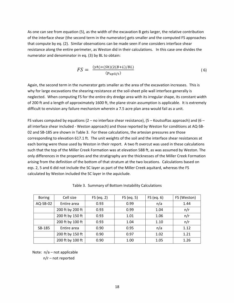
FS values computed by equations (2 – no interface shear resistance), (5 – Koutsoftas approach) and (6 –
all interface shear included ‐ Weston approach) and those reported by Weston for conditions at AQ‐SB‐
02 and SB‐185 are shown in Table 3. For these calculations, the artesian pressures are those
corresponding to elevation 617.1 ft. The unit weights of the soil and the interface shear resistances at
each boring were those used by Weston in their report. A two ft overcut was used in these calculations
such that the top of the Miller Creek Formation was at elevation 588 ft, as was assumed by Weston. The
only differences in the properties and the stratigraphy are the thicknesses of the Miller Creek Formation
arising from the definition of the bottom of that stratum at the two locations. Calculations based on
eqs. 2, 5 and 6 did not include the SC layer as part of the Miller Creek aquitard, whereas the FS
calculated by Weston included the SC layer in the aquiclude.
Table 3. Summary of Bottom Instability Calculations
Boring Cell size FS (eq. 2) FS (eq. 5) FS (eq. 6) FS (Weston)
AQ‐SB‐02 Entire area 0.93 0.99 n/a 1.44
200 ft by 200 ft 0.93 0.99 1.04 n/r
200 ft by 150 ft 0.93 1.01 1.06 n/r
200 ft by 100 ft 0.93 1.04 1.10 n/r
SB‐185 Entire area 0.90 0.95 n/a 1.12
200 ft by 150 ft 0.90 0.97 1.02 1.21
200 ft by 100 ft 0.90 1.00 1.05 1.26
Note: n/a – not applicable
n/r – not reported
19
The results of the calculations clearly show instability caused by uplift pressures. The assumption of the
thickness of the Miller Creek aquitard has a bigger effect on the computed FS than the assumption of
the interface shear strength. For example, the FS values vary from 0.9 to 1.05 for the 200 ft by 100 ft
cell at SB‐185, reflecting the impact of the interface shear assumptions, whereas the Weston FS is 1.26
for the thicker Miller Creek aquitard at the same location.
All factors of safety computed by eqs. 2, 5 and 6 are lower than those reported by Weston, and all are
less than acceptable value of 1.5 (and most are less than 1 indicating that an uplift failure would occur).
This result implies that the assumption one makes regarding interface shear resistance has no real
impact on the result of the calculation.
Finally, as documented in my October 27 report (Finno 204), stratigraphy defined by soundings CPT‐4
and borings SB‐163, SB‐182, SB‐183 and SB‐185 have lower FS against bottom heave due to artesian
pressures than does AQ‐SB‐02. The conditions at these locations, and those at CPT‐5, SB‐162, SB‐164
and SB‐181 have FS against uplift less than 1. The dry excavation scheme, even with a cell by cell
approach with minimum widths of 100 ft, are not safe with respect to bottom heave caused by the
artesian pressures in the Copper Falls aquifer, even if one accepts the minimum acceptable value of FS
of 1.25 that Weston espoused. As discussed in the next section, this value of 1.25 is not appropriate.
6.2.2 Minimum Factor of Safety against Bottom Uplift
Weston used a value of 1.25 as an acceptable value of FS against uplift, and again refers to the work by
Koutsoftas (2012) as justification. As discussed in detail in my report of October 27, 2014, an FS should
reflect the uncertainties inherent in an analysis and the consequences of failure. The case described by
Koutsoftas was an excavation through soft Bay Mud in San Francisco. The key elements in determining
the resistance to uplift are the unit weight and thickness of the Bay Mud as well as its undrained shear
strength. Geotechnical site investigations for the subway line he described were much more extensive,
with significantly more borings per area and numerous thin wall tube samples collected for testing. In
contrast to the Ashland Superfund Site, the more extensive boring program for a subway project in San
Francisco, or any congested urban area where subsurface conditions are generally well known, results in
less uncertainty in the stratigraphy at a site.
To see the variations in undrained shear strength of the soft Bay Mud, the undrained strength profile
from Koutsoftas (2012) is shown in Figure 7. Note that variations in both UU and field vane test results
are shown. There is clearly more scatter in the UU tests than the field vane tests. As described by Ladd
(1991) in his Terzaghi lecture, this trend is of large variations in UU strengths are to be expected because
of substantial reductions of effective stress in UU specimens as a result of sampling disturbance. Field
vane shear tests typically are made to define undrained shear strengths in the soft Bay Mud and these
are very appropriate for the soft clays at the Islais Creek project. The variability in SU in the Bay Mud in
this figure is much smaller than at the Ashland Superfund site on Figure 4, especially when one uses the
field vane results to define the undrained strength. For example, at a given elevation in the Bay Mud
20
the field vane strengths fall with a range of about 12 kpa (= 240 psf). In contrast, the range of strengths
shown in Figure 4 vary by more than 3000 psf in the stiff ML layer and about 600 psf in the softer CH
layers. Furthermore, the only direct measurement of shear strength in the cohesive soils in the Miller
Creek aquitard at AQ‐SB‐02 is one UU result. Clearly, there is much more uncertainty in the SU values at
the Ashland Superfund Site than at the Islais Creek site.
Also, Weston relied heavily on correlations between penetration test N values and values of unit weight.
As described in section 5.2.3, the uncertainties associated with these correlations, especially when there
is no extensive site specific or at least deposit specific correlations, are large as illustrated in Figure 5.
If values of FS should reflect the uncertainties in the key parameters affecting the analysis, as indicated
by Duncan and Buchignani (1975), then the FS for the excavation bottom uplift instability potential
should be greater at the Ashland Superfund Site than the values of 1.25 advocated by Koutsoftas for the
Islais Creek excavation. These higher uncertainties along with the high consequences of failure warrant
the use of a minimum acceptable value of FS of 1.5. Significantly, even Weston’s own calculations
presented in Table 4 do not satisfy this standard.
7. Design of Cantilevered Sheet Pile Wall is Inadequate
7.1 Weston Approach
Weston used ProSheet software developed by Skyline Steel Company that computes depth of
embedment, required section modulus, and maximum deflection at the top of a sheet pile wall. They
made their analyses at stratigraphies based on borings AQ‐SB‐02, AQ‐SB‐04 and SB‐185. They made the
following assumptions:
1. Drained shear strength parameters were assumed for soils on the retained (or active) side of the
sheet pile wall. Undrained shear strength parameters were assumed for the Miller Creek aquitard
on excavated (passive) side of the wall. They included the SC layer that as part of the aquitard in
their calculations.
2. The water table on excavated side of wall was assumed 2 ft below a 2 ft over‐excavation depth, or 4
ft below the surface of the Miller Creek Formation soils. This assumption was made because of the
possible need to excavate contaminants below elevation 590 ft and the potential need to dewater
the MCF soils by pumping from passive drainage trenches prior to excavation of these soils.
3. The artesian pore water pressures within the Copper Falls Formation were considered by assigning
the full artesian pressures to the active side of the wall but were neglected on the passive side.
4. Effect of upward seepage were considered by reducing the unit weight of soils on the passive side
using largest seepage gradient expected during dry dredge activities.
5. Impact loadings from wind generated waves were included as discussed in Appendix A of Exhibit 4.
Because no information was available for ice loading, wind generated waves were assumed to
govern the design.
21
Including an increase in embedment length of 20% over that needed for equilibrium of lateral forces,
Weston determined that the length of sheeting needed to be 37, 55 and 34 ft long at the AQ‐SB‐02, AQ‐
SB‐04 and SB‐185 locations. They recommended that a 55 ft long section be installed for a drive and pull
sequencing for the off shore conditions along the entire alignment. They recommended that the sheet
pile section be at least a AZ‐26‐700 section along the off shore alignment and a AZ‐38‐700 section along
the on shore alignment. The off shore segments were selected on the basis of drivability; the required
section modulus to fulfill bending requirements were smaller than this specified section.
Weston provided no details regarding the computation of the lateral deflection of the sheet pile wall,
other to indicate that is was computed by the ProSheet software.
7.2 Evaluation of Approach
Standard design of cantilever sheet pile walls consists of computing the net lateral pressures against a
wall using active and passive Rankine earth pressures and water pressures. Maximum bending
moments are computed from the net pressure distributions. The depth of embedment is determined as
the depth when moment equilibrium is satisfied. The depth of embedment is increased from the
computed value by 20 to 40% to account for the fact that full active and passive pressures are assumed
to act on the wall. While not explicitly stated in the Weston report, ProSheet software presumably
follows a similar procedure.
A separate calculation is needed to compute displacements of the sheet pile wall. Weston did not
provide any discussion about this procedure, but again referred to the ProSheet software. Because no
input data were presented or discussed other than shear strength parameters, presumably the
calculation is based on the net pressures acting on the wall and some assumption concerning the depth
of the point of fixity of the wall.
I claim no expertise with determining the wind‐generated wave loadings, and thus accept the values as
presented by Weston. The maximum lateral loads on the wall are generated by the imposed wave
loading. The shear strengths reported by Weston in their report represent the shear strength under
monotonic loadings. However, when one considers wave loading as a source of lateral loading on a
sheet pile wall, it is a cyclically applied load. Weston was silent about the effects of cyclic loading on the
strength and stiffness of the soil that supports the sheet pile wall.
When one designs sheet pile walls for on shore excavations, cyclically applied lateral loading is not a
design issue. Consequently there is little, if any, literature regarding such design issues or case histories
that can provide guidance in design. However there is a large body of literature regarding response of
driven piles and drilled shafts subjected to cyclically‐applied lateral loads.
Soil responses to laterally loaded piles are commonly defined in terms of p‐y curves, which represent the
relationship between the soil resistance, p, developed as a pile moves into the soil versus the
deformation of the pile, y. Curves defining this response for various soil types and loading conditions
have been incorporated into standard geotechnical practice. Figure 8 shows p‐y curves for cohesive
22
soils that are applicable to the soil conditions at the Ashland Site. Reese et al. (1975) presented the p‐y
curves in Figure 8a for static loading and in Figure 8b for cyclic loading in stiff clay in the presence of free
water. Note that a significant drop in resistance occurs in both static and cyclic cases when free water is
present, as is the case at the Ashland Superfund Site. Note that the drop in soil resistance is more
pronounced in the cyclic loading condition in that it takes less lateral pile movement to reach the
minimum “residual” value for the cyclic loading. Figure 9 shows a p‐y curve recommended for static
loading in stiff clay with no free water present. No softening response is noted in this curve. The
proposed sheet piles will be driven over water, and thus will have access to free water. The softening
behavior of the soil must be considered in their design.
While these curves are widely used in geotechnical practice – they are implemented as standard p‐y
curves in LPILE and COM626, two widely available, commercial computer codes – there is no such curve
for silt. However, Reese and Van Impe (2001) presented a p‐y curve for soils with both cohesion and
friction (so called Φ‐c soils, and this is shown in Figure 10. As recommended by Reese and Van Impe
(2001), this curve can be used for silts. There also is a noticeable drop in soil resistance after a certain
amount of pile displacement in this p‐y curve for silt. Details concerning the development of these p‐y
curves are found in the references, and often are included in commercial software for analyzing laterally
loaded piles.
In both clays in the presence of free water and silts, the predominant soils adjacent to the excavated
side of the sheet pile wall at the Site, there is pronounced reduction is resistance with as a pile deflects
lateral past a certain point. This softening of the soil resistance will make the lateral sheet pile
deformations larger than one would expect for static loading. This also implies that the curvature of the
wall and its corresponding bending moment would also be larger than computed for static conditions.
Note that the maximum moment depends on the curvature of the sheet pile. Weston’s report is silent
on the matter of cyclic loading effects on the lateral deflection and maximum moment.
No details are provided by Weston on how the maximum lateral deformation of the sheet pile was
computed, other than saying it was computed by ProSheet. The lateral pile deformation is important
because it must not exceed 12 inches at the top of the sheet pile, or at least that is my interpretation of
their report. Weston claims that the acceptable maximum lateral deflection at the top of the sheet pile
wall is 12 ft. This must be a typographical error, and it is assumed that the acceptable value is 12 inches.
Finally, Weston recommended that the sheet pile section be at least a AZ‐26‐700 section along the off
shore alignment and a AZ‐38‐700 section along the on shore alignment. The off shore segments were
selected on the basis of drivability; the required section modulus to fulfill bending requirements were
smaller than this specified section. It seems odd that the entire design (a heavier and more expensive
sheet) is changed without calculations on the advice of a steel sheet pile manufacturer.
23
8. Piping Factor of Safety is Below Industry Standards
8.1 Weston Approach
Weston estimated the upward gradient adjacent to the sheet pile wall, assuming installation of the
sheet pile and excavation of the soil within a 150 ft by 200 ft cell. They did so by combining results of
two separate analyses: the upward gradient caused by the artesian pressures in the Copper Falls aquifer
and the gradient arising from flow around the completed excavation caused by the difference in head
outside and inside the excavation.
The analysis for upward gradient caused by artesian pressures was made for subsurface conditions
defined by their design profile in their 2009 report (Weston 2009). They computed exit gradients of 1.7
x 10‐5 for this case. They did not present any calculations for the three design profiles in their 2014
report, and thus considered it insignificant compared to the flow around the sheeting mechanism.
The flow around the wall when the excavation was completed was made assuming the flow around the
sheet pile wall was for a case with more pervious soils (Bay sediments) above the dredge line overlying
less pervious soils (Miller Creek Formation) below the dredge line. Implicit in this assumption is that the
hydraulic conductivity was uniform in the Miller Creek Formation. They computed the FS against piping
as 3.66, 5.06 and 3.82 for conditions at AQ‐SB‐02, AQ‐SB‐04 and SB‐185 and considered these values
acceptable because they exceeded a minimum FS of 2.
8.2 Evaluation of Approach
Weston’s analysis of the upward gradient caused by artesian pressures was the same as presented in
Weston’s 2009 report, and was not changed. Thus they did not perform the analysis for any of the
three design profiles. Consequently, my comments made in the first report are applicable.
As noted in Finno (2014), a more critical condition than that assumed by Weston for the upward flow
from the Copper Falls aquifer was found at the CPT‐05 location. There, the majority of the soil between
the bottom of the excavation and the top of the aquifer is non‐plastic sandy silt, ML. While there are
only 4 Atterberg limits reported for samples of this ML soil encountered in the offshore borings, three of
the four indicated that the ML is non‐plastic. This type of soil is highly erodible. While the cone tip
resistance indicates the material is dense to very dense, the process of installing the sheet pile wall will
loosen the silt adjacent to the wall and create paths of preferential seepage. The critical location for the
initiation of piping is adjacent to the sheeting at the excavated ground surface. If piping occurs there, it
would lead to a catastrophic failure of the wall. Note that the length of the sheeting is recommended by
Weston to be 55 ft, and thus will extend into the Copper Falls aquifer at the CPT‐05 location, potentially
providing a direct path between the aquifer and the base of the excavation.
24
As indicated in Finno (2014), the exit gradient at the CPT‐04 location is 0.4. Accepting the value of
critical gradient is rounded to 1 for sake of significant numbers, the FS against piping is 2.5. This margin
of safety against the possibility of piping is less than industry standards. If piping were to occur, then
the sheet pile wall would collapse as a result of removal of the soil against its toe, leading to flooding of
the excavation.
Even without considering the additional flow around the sheet pile wall, the FS is 2.5 and less than
industry standard of 4 to 5. Note that Weston changed the acceptable FS from 4 to 5 in their original
report to 2 in their 2014 report. They did so without comment. Weston in their conceptual design
stated that this minimum FS should be between 4 and 5, and I agree.
9. Global Instability is Indicated Based on Analyses of Long Term Conditions
9.1 Weston Approach
To get an additional measure of the potential of basal heave due to a shear failure, Weston conducted
slope stability analyses of a completed excavation for the stratigraphies defined by AQ‐SB‐02 and AQ‐SB‐
04. They use the software Slope/W and computed the FS against a rotational failure using the method
of slices with the Spencer approach to calculate FS. They included an upward acting uniform surcharge
represent the potential destabilizing effects of the artesian pore water pressure. The pressure was
attenuated to the elevation of the base of the actual failure mass. This surcharge was only added to the
retained side of the failure mass. Weston used undrained shear strengths for the cohesive soils and
thus analyzed the end‐of‐construction condition. No evaluation of long term conditions were made.
They restricted the possible failure surfaces to within the Miller Creek aquitard and only considered
those that passed below the sheet pile wall. The length of the sheet pile for each section was that
computed by their design calculations and not the 55 ft length of sheeting recommended for the project
on the basis of drivability and availability of the section. They computed the FS against a rotational
failure within the Miller Creek Formation to be 1.73 and 1.63 for conditions at the AQ‐SB‐02 and AQ‐SB‐
04 locations, respectively.
9.2 Evaluation of Approach
Given the stiff clays and silts at the site and the relatively small excavated depth, one would not expect a
deep seated failure through the clays and silts to be a problem for short term conditions of the dry
dredge option. However given the artesian pressures in the Copper Falls aquifer, the effective stresses
in the aquifer will be low, more so when the top of the aquifer is located at a higher elevation. Because
the shearing resistance of the granular soils in the Copper Falls aquifer is proportional to the effective
stress, the shear strength of the sands near the top of the aquifer will be small and thus serve as a
potential failure surface for a global failure. When the FS against uplift is 1 or less, the effective vertical
stress at the top of the aquifer is zero, and the sand under these conditions has zero shear strength.

25
As discussed in Finno (2014), a mechanism that is appropriate for this mode of failure is a sliding block.
This mechanism is appropriate when a thin, low shear strength soil is encountered. This is the case as
the top of the Copper Falls aquifer when the uplift pressure equals the total vertical stress and thus the
effective stress is zero at the top of the aquifer. This condition implies that there is no shearing
resistance in the sand, and the shearing resistance along the central block is equal to 0. This analysis
was presented in my 2014 report for the subsurface conditions at CPT‐04, and the FS against sliding was
0.94 assuming drained conditions. Any FS less than or equal to one indicates a sliding failure will occur.
This FS is significantly less that the industry standard of 1.5 for long term analysis of global stability.
The issue then is how much time will be needed to attain this fully drained condition. Given that the dry
dredge excavation will last more than 1 construction season, appreciable dissipation of excess pore
water pressures will occur, especially in the ML strata in the Miller Creek Formation. Therefore, it is
standard practice to consider both short (undrained) and long (drained) term conditions for this
potential failure mode. Failure in terms of a global instability is a possibility for the long term conditions
for the dry dredge option, and is another indication of the unsuitability of the dry dredge option.
10. Sheet Pile Wall Will be Difficult to Construct
Construction procedures and details are very important in the design of any supported excavation
project and greatly impact the success or failure of such a project.
10.1 Weston Approach
While Weston claimed that the FS they computed in their five relevant and essential geotechnical
instability scenarios represented the off shore conditions for a full excavation footprint approach in
which sheet piling would initially be installed around the 7.5 acre perimeter of the dry excavation
footprint. Thereafter, water would be pumped from the interior, contaminated materials would be
excavated in the dry and the excavated zone would be backfilled. To provide a more construction
friendly approach, they proposed to instead create sheeted, subdivided cells with the 7.5 acre footprint,
as fully described on p. T.21 of their report.
10.2 Evaluation of Approach
A major consideration when designing sheet piling is the issue of drivability. Exhibit 4 of the Weston
report included reference to a discussion with a “Geotechnical Engineer from Skyline Steel Company”
who stated driving would be routine, and suggested that the sheets be initially set with heavy duty
vibratory hammer, then set to final depth with heavy duty impact hammer. No analyses were
conducted to evaluate the accuracy for this claim. Wave equation analyses are routinely performed for
major pile driving projects to evaluate the pile driving system, and could be done for this project as well.
The maximum force that can be transmitted down a pile is limited by the pile impedance, which
depends on the pile type and cross‐sectional area. One of the outputs of such analysis is the stresses in
26
the pile during driving. Another output is the maximum soil resistance that a pile‐pile driving system can
overcome. These two pieces of information can be used to determine if a pile can be driven to its design
depth without damage. Weston reported the results of no such analyses to support their claim.
As part of the cell by cell approach, Weston proposed to extract sheeting when done or use them as
“drive and pull.” Extracting sheets driven through clays may prove difficult due to set up that would
occur over time, an issue not discussed in the Weston report.
As discussed in Finno (2014), there also is the issue of lost interlocks during driving. Driving sheet pile at
some locations through very dense silts with cone tip resistances as high as 400 tsf and hard clays will
present a challenge to a contractor. More importantly, whenever gravel, cobbles and boulders are
encountered, the oversized material can cause the interlocks to split, resulting in a zone of concentrated
seepage, potential erosion of soil against the sheeting, and an ultimate collapse of the wall and release
of Lake Superior water into the excavation.
Given the fact that the Miller Creek formation is composed of two separate tills, some of which has been
deposited directly out of the ice, one should expect that gravel and boulders will be encountered when
driving sheet piles through this formation. There is direct evidence in some the boring logs. For
example, the Northern Technology boring log 88‐5 indicates a “schist boulder” at 23 to 24 ft depth. If a
boulder is encountered along the alignment, sheeting will not be able to advance past that depth.
Gravel is noted in many borings made both on and offshore. Damage to the interlocks between sheets
is likely at some locations, and may will lead to concentrated flow of water from the Lake side to the
excavated side of the sheet pile wall. This would lead to a collapse of the wall and subsequent flooding
of the excavation.
Weston acknowledged that some seepage will flow into the open excavation that would likely occur and
hence need to be treated. This is an acknowledgement that an installed sheet pile wall would not be
impervious under these conditions. The question is the quantity of leakage, especially given the
potential of losing sheet pile interlocks when gravel and/or when hard driving conditions are
encountered at some locations.
Weston also acknowledged that there is a possibility unanticipated subsurface conditions may be
encountered during the work that would have the effect of reducing one or more of the calculated FS
for the five instability scenarios to unacceptable values. They give an example that the contamination
could extend to a greater depth at some locations, and after excavation, the remaining thinner stratum
of Miller Creek aquitard would reduce the FS against uplift caused by artesian pressures in the Copper
Falls aquifer. They suggested that the water pressures in the aquifer could be reduced by either
pumping or relief wells. While this approach would increase the stability of the excavation, results of
analyses presented in this report and in Finno (2014) indicates this condition should be expected over a
significant portion of the 7.5 acres site, whether or not contaminants extend to greater depths than
anticipated. Therefore, such a system would need to be in place before excavation begins at each cell
for which the FS is below industry standards. This necessity will add significant costs and time to the
construction project, and the use of a dewatering system still would not mitigate all problems with the
27
dry dredge concept, most notably, the unsuitable driving conditions for the sheeting and subsequent
leakage through the sheeting.
11. Summary and Conclusions
This report summarizes my evaluation of the geotechnical conditions at the Ashland Lakefront
Superfund Site and associated impacts on the proposed dry dredge scheme and includes my evaluation
of the five essential geotechnical analyses presented by Weston. I reviewed the information available
in Weston’s final technical submittal and the reports and data listed in Section 3. This work supplements
my report dated October 27, 2014. I understand that the dry dredge scheme will entail driving a row of
sheet piles across the bay and around the shore line to provide an impervious wall. The scheme
proposed in the Weston’s final technical submittal calls for breaking up the dry dredge area into a
number of smaller cells comprised of sheet pile walls. Water will be pumped from the cells, the
contaminated sediments subsequently will be excavated, backfill placed and sheet piles extracted.
After reviewing the data and analyses presented in the Weston final technical submittal, I have reached
the following conclusions:
The excavation in a dry dredge scheme will not be stable because bottom heave due to artesian
water pressures will likely occur at some locations after soil has been excavated. Contrary to
Weston’s opinion, when bottom heave occurs, the excavation likely will be flooded by ground
water from the underlying Copper Falls aquifer.
The Factors of Safety (FS) used in Weston’s analyses do not appropriately account for variability
in Site subsurface conditions, engineering parameters and loading condition. The FS should
reflect uncertainties in subsurface conditions, engineering parameters, loading conditions and
consequences of failure. The FS used by Weston did not adequately consider these factors in all
cases, particularly when considering the potential for bottom heave from the artesian pressures
in the Copper Falls aquifer.
Weston identified the subsurface conditions at boring AQ‐SB‐02 as the most critical for bottom
heave due to artesian pressures and concluded that the factor of safety for the entire
excavation based on these conditions was adequate based on assuming that the shear strength
of the Miller Creek Formation at the edges of the excavation between the bottom of the
excavation and the top of the Copper Falls Formation could be counted upon to resist the uplift
forces. They also presented an analysis that purported to show the silty sand/clayey sand layer
could be considered as part of the Miller Creek Formation aquiclude and would also resist the
uplift forces. Their analysis is incorrect for the following reasons:
28
o Stratigraphy defined by soundings CPT‐4 and borings SB‐163, SB‐182 and SB‐183 and SB‐
185 have lower FS against bottom heave due to artesian pressures than does AQ‐SB‐02.
The conditions at these locations, and those at CPT‐5, SB‐162, SB‐164 and SB‐181 have
FS against bottom heave is less than 1 at each location.
o The Weston dominant clay fraction analysis based on a method proposed by Mitchell
(1976) is incorrect. Weston incorrectly defined the amount of clay sized particles from
the particle size distributions for samples obtained from the silty/ clayey sand layer in
boring AQ‐SB‐02. When the proper amount of clay sized particles are employed in the
Weston analysis, the analyses shows that there is insufficient clay content for the clay to
dominate the behavior of the silty/sandy clay layer. Their conclusion that this layer can
be considered to have low permeability and thus be part of the Miller Creek Formation
aquiclude is incorrect. This makes the aquiclude that resists uplift from the artesian
pressure 8.15 ft thinner at the AQ‐SB‐02 location than assumed by Weston.
o Weston assumes the shear strength of parts of the Miller Creek Formation can be relied
upon to resist uplift from the artesian pressures, and as justification, cite a work by
Koutsoftas (2012). However the geometry of the excavation they cite is only 36 ft wide
and is very long relative to its width. Koutsoftas considers the uplift conditions as plane
strain and does not consider the shear strength at the ends of the excavation when
computing FS against uplift.
o Weston only presents an uplift calculation that considers the entire dry dredge area,
and relies upon the shear resistance of the Miller Creek Formation at the edges of the
excavation between the bottom of the excavation and the top of the Copper Falls
Formation, including the silty/clayey sand layer mischaracterized as low permeability
soil. The width of the entire excavation is 200 ft and its length approximately 1600 ft.
Following Weston’s own reference, the Koutsoftas approach would model this as a
plane strain condition and make the calculation per ft of sheet pile wall length. This
approach yields a FS of 0.99, less that the value of 1.44 computed by Weston for the
same conditions.
o The analysis of bottom heave at the AQ‐SB‐02 location due to artesian water pressures
in the Copper Falls aquifer based on the correct approach indicates that an uplift failure
will occur. The computed values of FS at this location and at SB‐185 for various
assumptions regarding interface shear strength are lower than those reported by
Weston, and all are less than acceptable value of 1.5 (and most are less than 1 indicating
that an uplift failure would occur).
29
The dry excavation scheme, even with a cell by cell approach with minimum widths of 100 ft, is
not safe with respect to bottom heave caused by the artesian pressures in the Copper Falls
aquifer, even if one accepts the minimum acceptable value of FS of 1.25 that Weston espoused.
Even without considering the additional water flow around the sheet pile wall, the FS against
piping due to upward flow at the location of CPT‐05 is 2.5 and less than industry standard of 4 to
5. Note that Weston changed the acceptable FS from 4 to 5 in their 2009 report to 2 in their
2014 report. They did so without comment. Weston in their conceptual design stated that this
minimum FS should be between 4 and 5, and I agree. If piping were to occur due to upward
flow along the sheet pile, then the sheet pile wall would collapse as a result of the removal of
the soil against its toe, leading to flooding of the excavation.
Weston’s design did not consider a global instability failure mode that encompasses the entire
sheet pile wall and passes through the underlying Copper Falls Formation. The FS against this
global instability may be computed assuming a sliding block model when the excavation is at
final depth. Given that the dry dredge excavation will last more than 1 construction season,
appreciable dissipation of excess pore water pressures will occur, especially in the ML strata in
the Miller Creek Formation. Therefore, it is standard practice to consider both short (undrained)
and long (drained) term conditions for this potential failure mode. Failure in terms of a global
instability is a possibility for the long term conditions for the dry dredge option, and is another
indication of the unsuitability of the dry dredge option. Failure in this case implies that a mass
of soil encompassing the wall will slide into the excavation and subsequently flooding it.
Weston’s design of the sheet pile wall was inadequate in that it did not adequately account for
expected loading conditions. While they included the effects of wave loadings such that the top
of the sheet piles will be at elevation 622 ft, their design did not consider the effects of cyclic
loading on the shear strength of the Miller Creek formation silts and clays. Cyclically applied
lateral loads have the effect of significantly reducing the resistance of the soil near the ground
surface, such that use of monotonically defined shear strengths are inappropriate. Sheet pile
walls installed on shore normally are not designed to resist cyclic lateral loads such as those
induced by waves, but guidance can be found by looking at the large body of literature on piles
subjected to cyclic lateral loads.
Weston’s design of the sheet pile wall was inadequate in that it did not account for
development of water filled gaps during period of high water and cyclic loadings, or the
directional effects of wave loadings. Sheet pile wall will provide resistance to bending and
tensile stresses, but not compressive stresses. Therefore, when the wall has a 90 degree bend,
some bracing will be required to ensure stability. Furthermore, Weston provided no details
regarding how the movements of the sheet pile wall were computed, a critical factor in
determining if the wall will be overtopped during a storm resulting in flooding of the excavation.
30
Weston’s design of the sheet pile wall results in a sheet pile wall that will not be able to be
constructed such that it will perform as intended. Weston acknowledged that there will be
leakage through the sheet pile wall, but does not specifically address the quantity of leakage,
other that it would be reduced by using a cell by cell approach. The quantity of leakage,
especially given the potential of losing sheet pile interlocks when gravel and/or when hard
driving conditions are encountered at some locations, has a major impact on whether or not a
sheet pile wall would perform as it was designed.
There also are a number of significant construction‐related difficulties associated with the dry
dredge option not addressed in their report. It will be very difficult to construct the sheet pile
wall and maintain its function as an “impervious” barrier as well as its structural integrity. It will
be difficult to install sheeting to required depth through the hard portions of the glacial tills. Till
refers to any soil that is deposited from a glacier and thus includes soils deposited in many ways.
Significant variations in its composition should be expected within the Site, given its size.
Concentrated flows of water through the sheeting could develop as a result of losing the
sheeting interlocks when driving in tills with gravel and boulders, which would lead to a collapse
of the sheet pile wall and subsequent flooding of the excavation.
For these reasons, and as detailed in the body of the report, it is my opinion that the proposed dry
dredge scheme is not safe or implementable at the Site, because of the potential for bottom heave,
global instability and various design and/or constructability concerns discussed herein. A wet dredge
approach would eliminate these risks, and is thus a far better solution to the geotechnical challenges of
the project.
.
31
12. References
Clayton, L. (1984), “Pleistocene Geology of the Superior Region, Wisconsin,” Lee Clayton, Information
Circular Number 46, Wisconsin Geological & Natural History Survey.
Duncan, J.M. and Buchignani, A.L. (1975). “An Engineering Manual for Slope Stability Studies,” Dept. of
Civil Engineering, University of California, 83 p.
Finno, R.J. (2014), “Evaluation of Geotechnical Conditions and Their Impact on Proposed Dry Dredge
Removal Plan, Ashland/Northern States Power, Lakefront Superfund Site,” report prepared for Northern
States Power – Wisconsin, 76 p.
Koutsoftas, D.C. (2012). “State of Practice: Excavations in Soft Soils,” Proceedings, Geotechnical
Engineering State of Art and Practice, Geotechnical Specialty Publication 226, ASCE, K.Rollins and D.
Zekkos, eds., p. 678‐728.
Kulhawy, F. H. and Mayne, P.W. (1990). “Manual on Estimating Soil Properties for Foundation Design,”
Final Report EL‐6800, Research Project 1493‐6, Electric Power Research Institute.
Ladd, C.C. (1991). “Stability Evaluation during Staged Construction, the 22nd Karl Terzaghi Lecture,”
Journal of Geotechnical Engineering, ASCE, Vol.117, No. 4, 540‐615.
Mitchell, J.K. (1976). Fundamentals of Soil Behavior, John Wiley & Sons, New York, NY, 422 p.
NAVFAC, (1986). Soil Mechanics DM7.1, Naval Facilities Egnieering Command, Alexandria, VA, 355 p.
Reese, L.C. and Van Impe, W.F. (2001). Single Piles and Pile Group under Lateral Loading, A.A. Balkema,
463 p.
Reese, L.C., Cox, W.R. and Koop, F.D. (1975), “Field Testing and Analysis of Laterally Loaded Piles in Stiff
Clays,” paper no, OTC 2312, Proceedings, Seventh Offshore Technology Conference, Houston, Texas.
Sowers, G. (1979). Introductory Soil Mechanics and Foundations, 4th edition, Macmillan, New York, NY,
621 p.
Terzaghi, K. and Peck, R.B. (1967). Soil Mechanics in Engineering Practice, 2nd Edition, John Wiley & Sons,
New York, NY, 729 p.
US Steel Corporation (1975). “USS Steel Sheet Piling Design Manual,” Pittsburgh, PA, 132 p.
Weston Solutions, Inc. (2009). Technical Memorandum, Conceptual Geotechnical Assessment for
Sediment Removal, Ashland Northern States Power Lakefront site,” Weston Solutions, Inc. Nov. 20,
2009 report.

32
Figure 1. Stratigraphy at AQ‐SB‐02
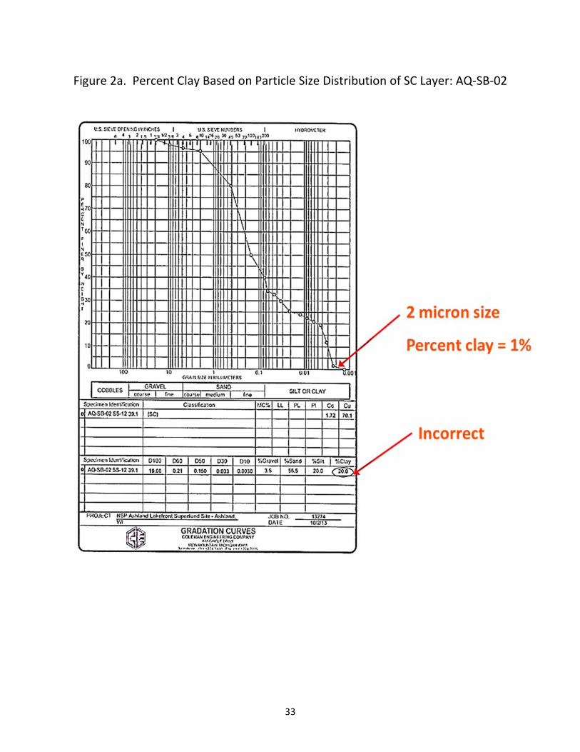
33
Figure 2a. Percent Clay Based on Particle Size Distribution of SC Layer: AQ‐SB‐02
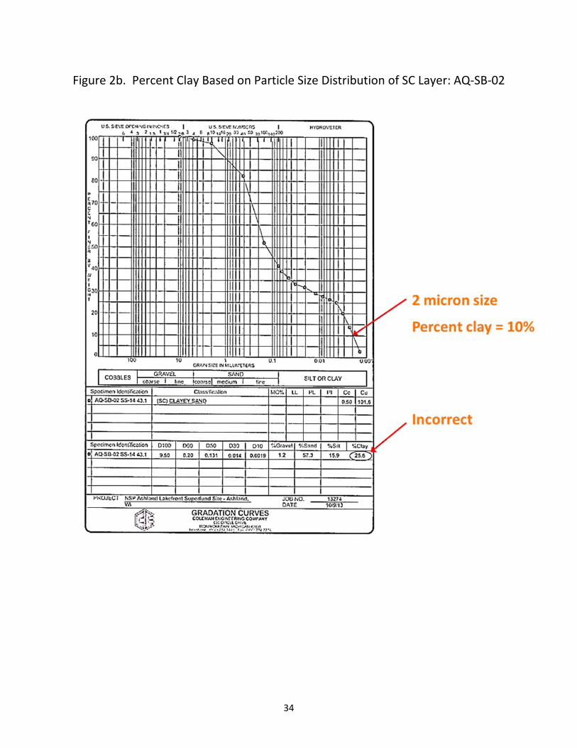
34
Figure 2b. Percent Clay Based on Particle Size Distribution of SC Layer: AQ‐SB‐02
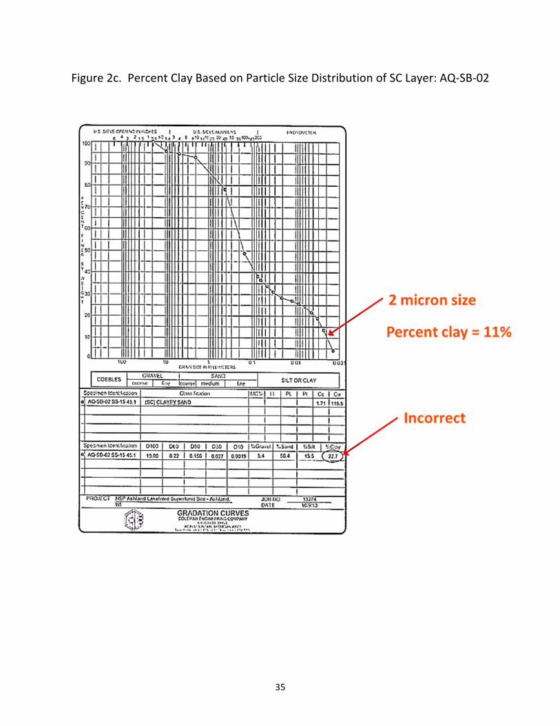
35
Figure 2c. Percent Clay Based on Particle Size Distribution of SC Layer: AQ‐SB‐02
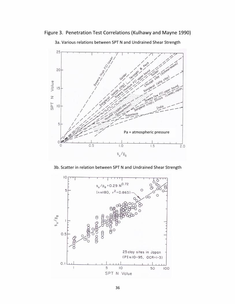
36
Figure 3. Penetration Test Correlations (Kulhawy and Mayne 1990)
3a. Various relations between SPT N and Undrained Shear Strength
3b. Scatter in relation between SPT N and Undrained Shear Strength
Pa = atmospheric pressure
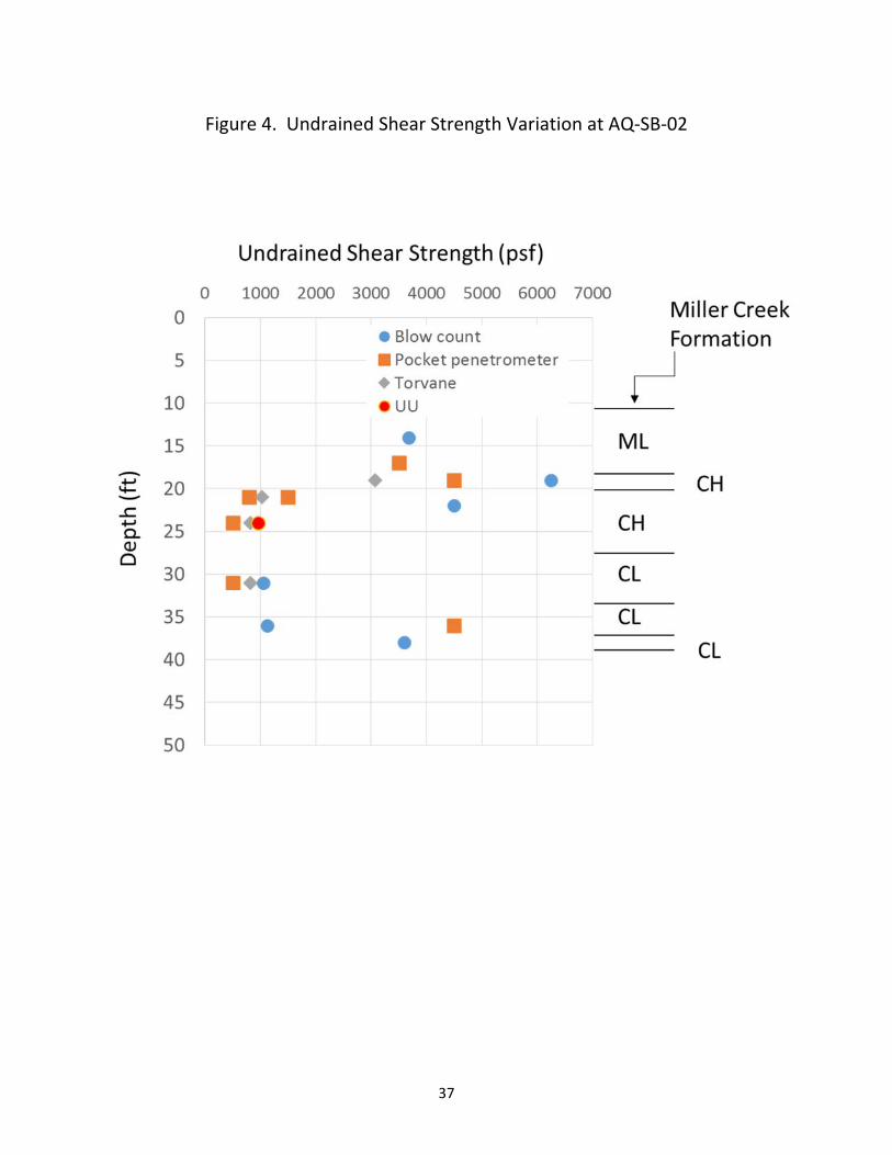
37
Figure 4. Undrained Shear Strength Variation at AQ‐SB‐02
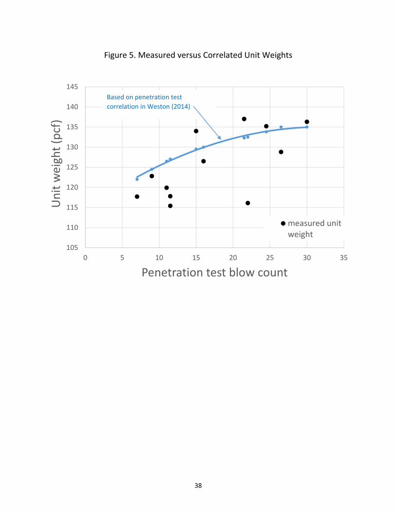
38
Figure 5. Measured versus Correlated Unit Weights
105
110
115
120
125
130
135
140
145
0 5 10 15 20 25 30 35
Unit weight (pcf)
Penetration test blow count
measured unitweight
Based on penetration test
correlation in Weston (2014)
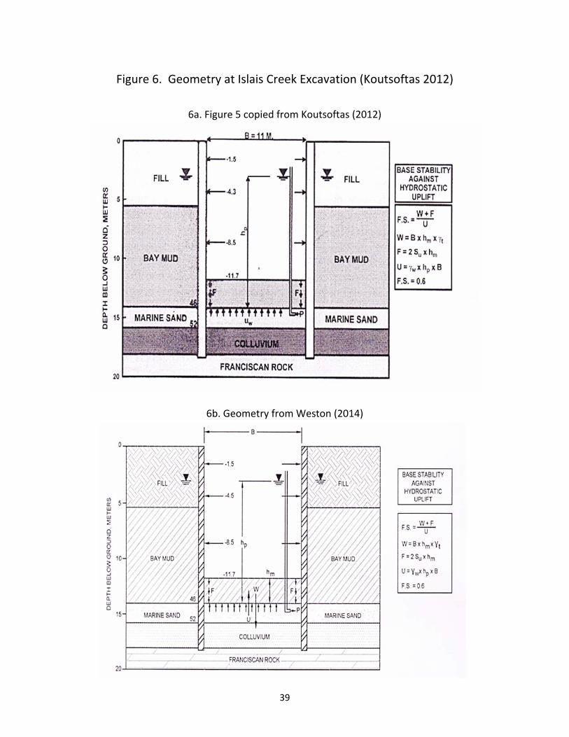
39
Figure 6. Geometry at Islais Creek Excavation (Koutsoftas 2012)
6a. Figure 5 copied from Koutsoftas (2012)
6b. Geometry from Weston (2014)
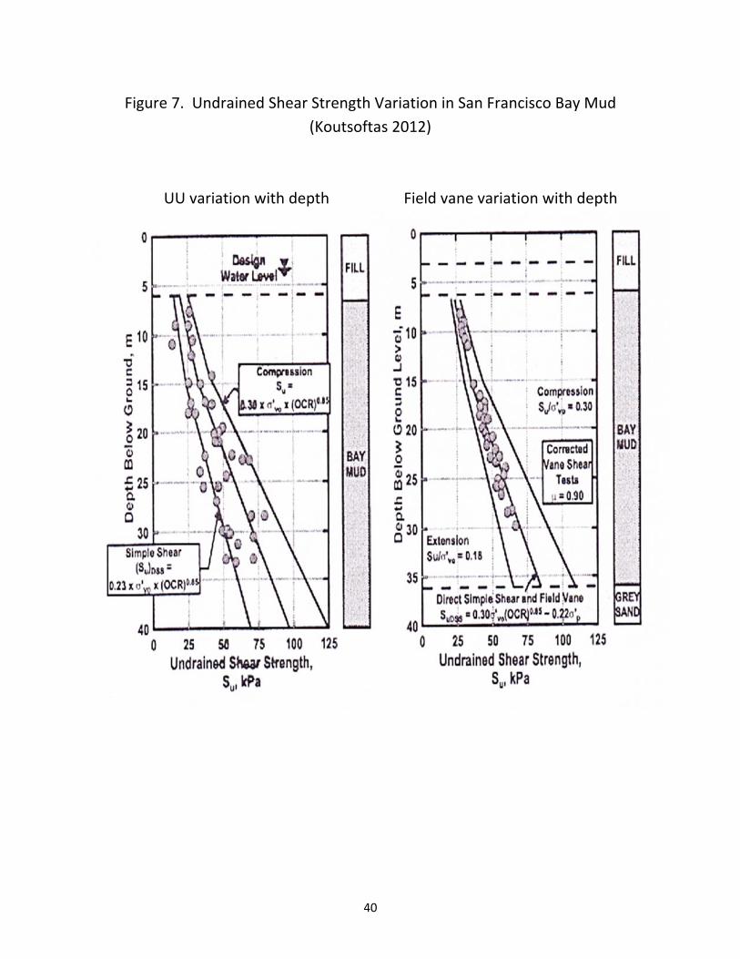
40
Figure 7. Undrained Shear Strength Variation in San Francisco Bay Mud
(Koutsoftas 2012)
UU variation with depth Field vane variation with depth
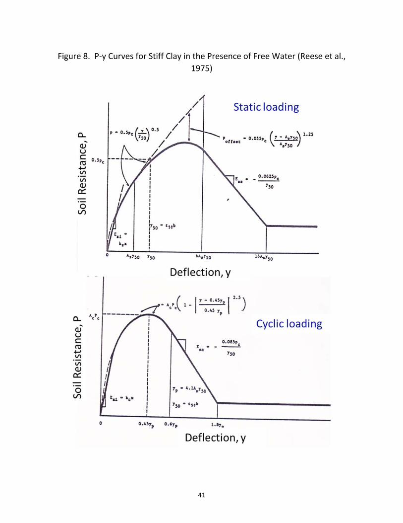
41
Figure 8. P‐y Curves for Stiff Clay in the Presence of Free Water (Reese et al.,
1975)
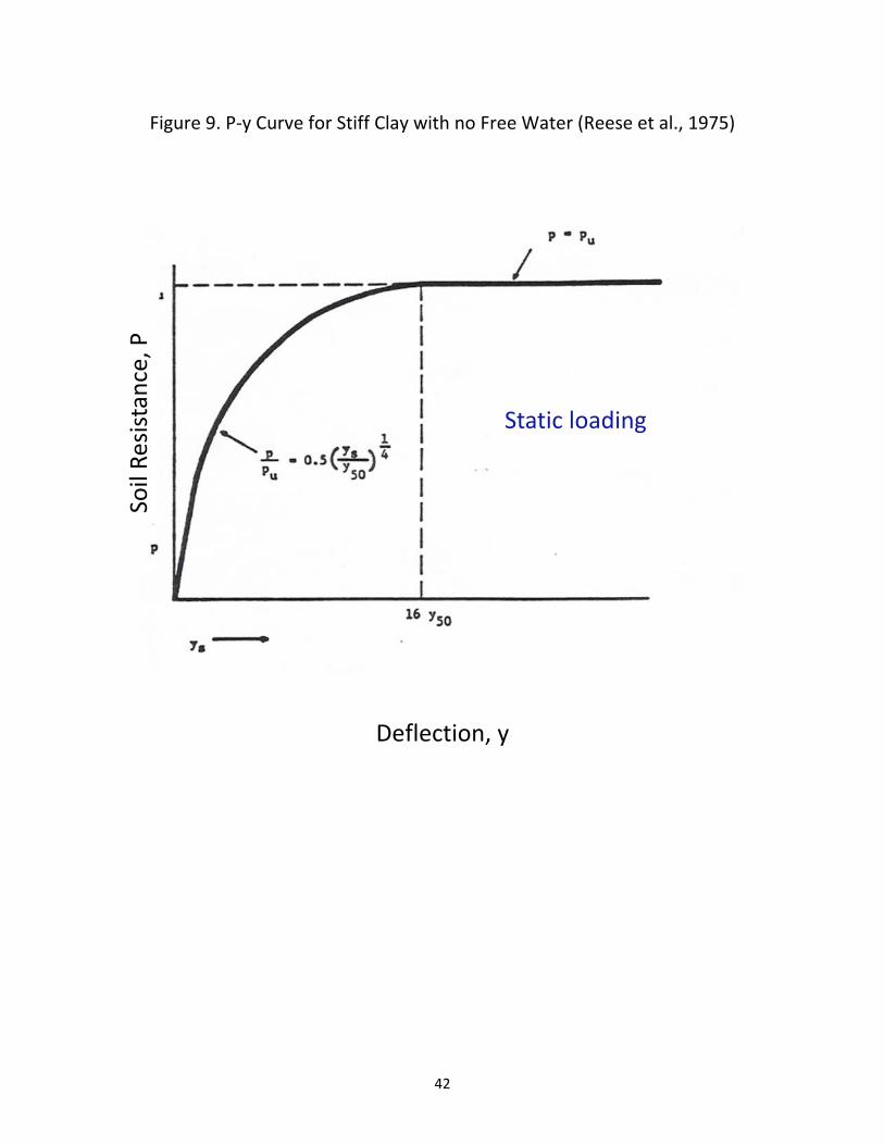
42
Figure 9. P‐y Curve for Stiff Clay with no Free Water (Reese et al., 1975)
Deflection, y
Soil Resistance, P
Static loading
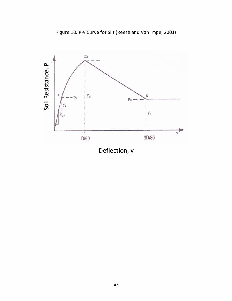
43
Figure 10. P‐y Curve for Silt (Reese and Van Impe, 2001)
Deflection, y
Soil Resistance, P

44
Appendix
Curriculum Vitae
Richard J. Finno
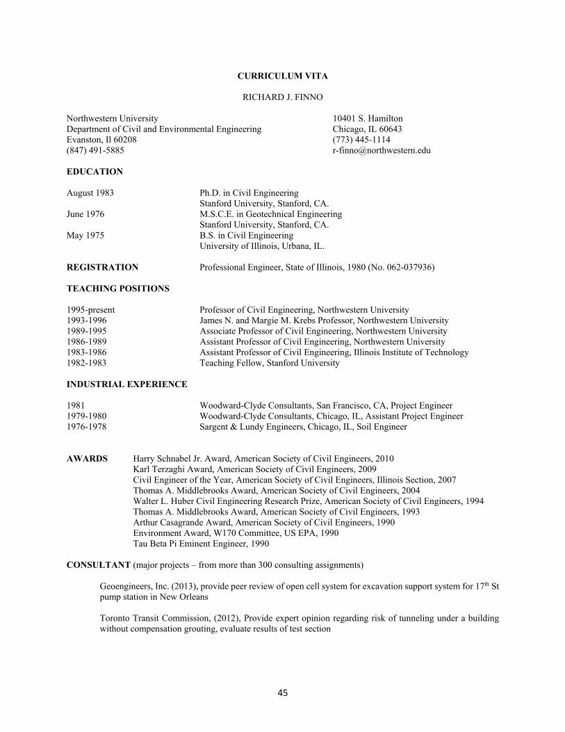
45
CURRICULUM VITA
RICHARD J. FINNO Northwestern University 10401 S. Hamilton Department of Civil and Environmental Engineering Chicago, IL 60643 Evanston, Il 60208 (773) 445-1114 (847) 491-5885 [email protected] EDUCATION August 1983 Ph.D. in Civil Engineering Stanford University, Stanford, CA. June 1976 M.S.C.E. in Geotechnical Engineering Stanford University, Stanford, CA. May 1975 B.S. in Civil Engineering University of Illinois, Urbana, IL. REGISTRATION Professional Engineer, State of Illinois, 1980 (No. 062-037936) TEACHING POSITIONS 1995-present Professor of Civil Engineering, Northwestern University 1993-1996 James N. and Margie M. Krebs Professor, Northwestern University 1989-1995 Associate Professor of Civil Engineering, Northwestern University 1986-1989 Assistant Professor of Civil Engineering, Northwestern University 1983-1986 Assistant Professor of Civil Engineering, Illinois Institute of Technology 1982-1983 Teaching Fellow, Stanford University INDUSTRIAL EXPERIENCE 1981 Woodward-Clyde Consultants, San Francisco, CA, Project Engineer 1979-1980 Woodward-Clyde Consultants, Chicago, IL, Assistant Project Engineer 1976-1978 Sargent & Lundy Engineers, Chicago, IL, Soil Engineer AWARDS Harry Schnabel Jr. Award, American Society of Civil Engineers, 2010
Karl Terzaghi Award, American Society of Civil Engineers, 2009 Civil Engineer of the Year, American Society of Civil Engineers, Illinois Section, 2007 Thomas A. Middlebrooks Award, American Society of Civil Engineers, 2004 Walter L. Huber Civil Engineering Research Prize, American Society of Civil Engineers, 1994
Thomas A. Middlebrooks Award, American Society of Civil Engineers, 1993 Arthur Casagrande Award, American Society of Civil Engineers, 1990 Environment Award, W170 Committee, US EPA, 1990 Tau Beta Pi Eminent Engineer, 1990 CONSULTANT (major projects – from more than 300 consulting assignments)
Geoengineers, Inc. (2013), provide peer review of open cell system for excavation support system for 17th St pump station in New Orleans Toronto Transit Commission, (2012), Provide expert opinion regarding risk of tunneling under a building without compensation grouting, evaluate results of test section
46
Wiss, Janney, Elstner & Associates, Inc., Northbrook, IL 1989-2014 (investigations of damage to bridges, multi-story buildings, concrete pile-supported marine structures and retention systems; evaluation of construction problems and structural failure of large diameter, self-sinking caissons in Dearborn, MI) GeoSyntec Consultants, (2008-2010) Geotechnical Assurance review of design of LNG facility, including deep soil mix treatment for foundations and retaining structures. STS Consultants, (2007) Peer review of excavation support system for the Spire building, Chicago, IL STV Ltd, 2004-2006, (Board of Consultants, Block 37 development in Chicago – subway tube connections) Department of Transportation of the City of Chicago, 1999 (evaluation of design and construction of retention system)
A. Epstein & Sons International, Inc., 1999 (evaluation of MSE retaining wall failure) Montgomery Watson, Sacramento, CA, 1998 (sunken shaft design)
Los Angeles MTA, 1994-1996, (provide peer review regarding distressed areas in subway tunnel under construction; investigate causes of tunnel collapse)
Ralph M. Parsons Co., Pasadena, CA, 1989, 1993-6, 2003-5 (investigation of excavation effects on adjacent pile-supported structure; slope instability evaluations; retaining wall studies; solute transport studies; foundation evaluation studies)
US Environmental Protection Agency, Washington, DC, 1989, member of Land Application Peer Review
Committee, (scientific peer review of US EPA standards 40 CFR PART 503) Harrison Western Corp., Denver, CO, 1986 (investigation of shaft failure) AFFILIATIONS Diplomate Geotechnical Engineering, Academy of Geo-Professionals Member: Geo-Institute of ASCE American Society of Civil Engineers (ASCE), Illinois Section International Society of Soil Mechanics and Geotechnical Engineering (ISSMGE) US Universities Council on Geotechnical Engineering Research (USUCGER) PROFESSIONAL COMMITTEES AND ACTIVITIES International: International Society of Soil Mechanics and Geotechnical Engineering
Member, Technical Committee 207, Soil-Structure Interaction and Retaining Walls, ISSMGE (2010-present) Member, Editorial Board, Acta Geotechnical, (2005-present) Member, Technical Committee 28, Underground Construction in Soft Ground, ISSMGE (2008-2010) Member, Advisory Board, Italian Geotechnical Journal, (1998-2009)
Co-Chairman, U.S. National Society of ISSMFE paper review for Thirteenth International Conference of Soil Mechanics and Foundation Engineering, 1994 National: American Society of Civil Engineers
At-large Trustee, Board of Directors, Academy of Geo-Professionals (2013-2016) Member, Organizing Committee, Joint GeoInstitute–Structural Engineering Institute 2016 Congress
47
Technical Program Director and co-editor of proceedings, ER2010 Earth Retention Conference 3 (2010) Editor, Journal of Geotechnical and Geoenvironmental Engineering, (2004-2007) Chair, Awards Committee, Geo-Institute, ASCE, (2002-2005) Member, Awards Committee, Geo-Institute, ASCE (1999-2001; 2011-present) Member, Technical Coordinating Council, Geo-Institute, ASCE (1996-1999)
Board Member and Treasurer, USUCGER (1996-1999) Co-Chairman, 1996 Geotechnical Engineering Congress, Madison WI
Chairman, Earth Retaining Structures Committee, Geotechnical Engineering Division (1994 -1998) Member, Earth Retaining Structures Committee, Geotechnical Engineering Division (1989-present)
Member, Editorial Board, Journal of Geotechnical Engineering (1986-1997) Member, Soil Properties Committee, Geotechnical Engineering Division (1984-1988) National Science Foundation Member of proposal review panels for Geotechnical, Geoenvironmental and Geomechanical
Systems, Earthquake Hazard Mitigation and Career award Programs
Chairman, Proposed Experiments/Uses Committee, NSF Workshop on Selection and Management of National U.S. Geotechnical Test Sites, 1991
Member of peer review team of NSF-sponsored Engineering Research Center at Texas A&M University, 1991 (Offshore Technology Research Center)
Proposal reviewer U.S. Geological Survey Proposal reviewer Local: American Society of Civil Engineers Geotechnical Engineering Division, Illinois Section Secretary/Treasurer, 1985-1986 Vice Chairman, 1986-1987 Chairman, 1987-1988 Illinois Section, Board of Directors, 1987-1988 and 1991-1993 RESEARCH ACTIVITIES Grants Awarded: Northwestern “GOALI: Strength loss in clays during earthquake and other cyclic loading,” National Science
Foundation, $451,922, (2014-2017)
“GOALI: Effects of gas in design and verification of blast densification of liquefiable sands,” National Science Foundation, $478,041, (2012-2015)
"Planning Visit for Developing New International Collaborations," National Science Foundation, $23,600, (2112)
“Condition Monitoring of Urban Infrastructure,” Infrastructure Technology Institute, $158,000 (2011-12)
48
“Advancing the Capabilities of Adaptive Management Techniques in Geotechnics,” National Science Foundation, $450,806, (2009-2012)
“Design and Verification of Blast Densification for Highway Embankments on Liquefiable Sands,” Infrastructure Technology Institute, $260,956 (2008-10)
“GOALI: Dynamic Soil Properties: Effects of Construction–induced Stress Changes,” National
Science Foundation, $331,245, 2008-2011
“Condition Monitoring of Urban Infrastructure,” Infrastructure Technology Institute, $591,501 (2007-09)
“Copperative Research: A Joint NU and UIUC Project for the Development of New Integrated Tools for Predicting, Monitoring, and Controlling Ground Movements due to Excavations,” National Science Foundation, $2,066,905 (2002-2007)
“Condition Monitoring of Urban Infrastructure,” Infrastructure Technology Institute, $293,887
(2006)
“Automated Deformation Monitoring,” Infrastructure Technology Institute, $169,363 (2004-2005) “Nondestructive Evaluation of Concrete with Flexural Waves,” Infrastructure Technology Institute,
$236,290 (2004-2005)
“Performance Monitoring and Condition Assessment of the Excavation and Support System for the Lurie Research Center,” Facilities Management, Northwestern University, $37,120 (2002)
"Allowable Deformations of Gas Mains Adjacent to Deep Excavations," Infrastructure Technology Institute, $167,757 (2002-2003) "Improved Conditioning Monitoring of Bridges: Non-destructive Evaluations of Foundations," Infrastructure Technology Institute," $140,667 (2002-2003)
"Analysis of the Performance of the Chicago-State Subway Station and its Effects on Adjacent Structures," Infrastructure Technology Institute, $187,561, (2001) "Improved Conditioning Monitoring for Bridge Management: Non-destructive Evaluations of Existing Foundations," Infrastructure Technology Institute," $88,311 (2001) “Objective Updating of Design Predictions for Supported Excavations using Construction Monitoring Data,” National Science Foundation, $224,585 (2001-2004) “In situ Nondestructive Evaluation of Concrete Piles,” Naval Facilities Engineering Command, $25,564 (2001)
"Improved Conditioning Monitoring for Bridge Management: Non-destructive Evaluations of Existing Foundations," Infrastructure Technology Institute," $79,954 (2000)
"Computability of Material Instabilities – New Methods and Case Study," National Science Foundation, CMS-0085664, $142,576, Co-principal investigator with T Belytschko (2000-2001)
"Evaluation of Capacity of Micropiles Embedded in Rock," Infrastructure Technology Institute," $24,800 (2000-2001)
49
"Geotechnical Monitoring of Chicago-State Subway Station," Wiss, Janney, Elstner Associates, Inc., $92,500 (1999-2001)
"Analysis of the Performance of the Chicago-State Subway Station and its Effects on Adjacent Structures," Infrastructure Technology Institute, $113,904. 1999-2000
"Effects of Strain Localization on Fault Gouge Constitutive Relations," US Geological Survey, $55,000 (1998)
"Progressive Failure in Overconsolidated Soils," National Science Foundation through subcontract with University of Colorado at Denver , $44,000, (1998-1999)
"Effects of Strain Localization on Fault Gouge Constitutive Relations," US Geological Survey, 134-HQ-97-GR-03007, $60,000 (1997)
"Research Equipment Proposal: Image Analysis of Internal Deformations during Shear," National
Science Foundation, CMS-9610373, $14,000 (1997)
"Support of US University Council on Geotechnical Engineering Research," National Science Foundation, CMS-9610357, $55,000 (1997-2000) "Innovative Techniques of Foundation Rehabilitation in Restricted Access Environments," Infrastructure Technology Institute, $32,960 (1996-1997)
"Time Domain Reflectometry (TDR) Cable and Grout System to Telemetrically Monitor Soil Slope Stability," National Science Foundation Grant No. CMS-9523236, $139,996, Co-principal investigator with CH Dowding (1995-1997)
"NDE of Drilled Shafts at NGES Site," Federal Highway Administration, $24,938, (1995-1996)
"Improved Conditioning Monitoring for Bridge Management: Non-destructive Evaluations of Existing Foundations," Infrastructure Technology Institute," $499,080, (1994-1999)
"Improved Conditioning Monitoring for Bridge Management: Task 4 Foundation Problems,"
Infrastructure Technology Institute," $154,846, co-principal investigator with CH Dowding (1993) "National Geotechnical Engineering Experimentation Site at Northwestern University," subcontract
to University of New Hampshire as part of National Science Foundation Grant, $76,000, (1992-1996)
"Experimental Evaluation of Reservoir Bottom Remediation Material: Ludington Pumped
Storage Facility," Ebasco Services Inc., $47,820, (1991-1992)
"Post Peak Behavior of Granular Soils and its Effect on Undrained Steady State Strength," National Science Foundation Grant No. BCS-9019755, $160,064, (1991-1993)
"Soil Properties Measurements Using Oscillating Electro-Kinetic Counter Pressures," National Science Foundation Grant No. MSS-9023540, $140,000, Co-principal investigator with J.R. Feldkamp (1991-93)
"Research Equipment for Geomechanics Testing," National Science Foundation, Grant No.
MSM-8800796, $45,000 (1988).
50
"Observation and Prediction of Field Behavior of an Embankment and a Braced Cut in University Clay, Evaluating the State-of-the-Art," National Science Foundation, Grant No. MSM-8796169, $140,578, (1987-1989).
Illinois Inst. "Evaluation of Creep-Induced Effective Stress Changes of Clay," Engineering Foundation of Technology Research Initiation Grant RI-A-84-1, $17,000, (1984). Industry-Supported Activities:
Pile Prediction Symposium, 1989 Foundation Engineering Congress, Evanston, Il., Organized and directed detailed load test program. Three construction and six consulting firms donated construction, instrumentation, and in situ testing.
NSF-supported activities:
Organized workshop in Cambridge, UK for developing new international collaborations for research on underground infrastructure, December 2012 Participant in 2nd Japan-US Workshop on Testing, Modeling and Simulation in Geomechanics, Kyoto Japan, September 2005 Participant in Assisting and Encouraging Student Opportunities for Post-undergraduate Study (AESOPS). workshop, Washington D.C., May, 2002 Participant in U.S.-Taiwan Geotechnical Engineering Collaboration Workshop, Taipei, Taiwan,
January, 1995.
Participant in U.S.-Scandinavian Workshop on Geotechnical Engineering Research Collaboration, Trondheim, Norway, June, 1994.
Reporter for working group in U.S.-France Workshop on Recent Advances in Geomechanical, Geotechnical and Geo-Environmental Engineering, Paris, France, June, 1992.
Reporter for working group on Prototype Testing and Behavior Prediction at the Workshop on
Establishment of National Test Sites for Earthquake Engrg and Geotechnical Engrg. Research, 1988
Participant in France - U.S. CNRS-NSF Workshop on "Strain Localization and Size Effect Due to Cracking and Damage," Cachan, France, Sept., 1988.
Presented overview of on-going research program, "Case Histories in Geotechnical Engineering", at NSF MSME Solid and Geomechanics Program Review, Washington, D.C., March, 1988.
Laboratory Development Secured funds and made operational servo-controlled testing devices including three triaxial, one
direct simple shear and one kinematically unconstrained, heavily-instrumented plane strain compression apparati in Northwestern University Geotechnical Engineering Laboratory; developed laboratory device to rapidly measure permeability of clays using alternating current electro-kinetics; added digital image analysis capabilities for mechanical testing of soils; incorporated bender elements and local strain gages to measure very small strains in triaxial device.
51
PUBLICATIONS Books (editor) Earth Retention Conference 3, Proceedings of the 2010 Earth Retention Conference, Geo-Institute of ASCE, R.J. Finno, Y.M.A. Hashash and P. Arduino, eds., Geotechnical Specialty Publication 208, August 2010, 941 p. Design and Construction of Earth Retaining Systems, Proceedings of sessions of Geo-Congress 98, sponsored by the Earth Retaining Structures Committee of the Geo-Institute, Boston, MA., R.J. Finno, Y. Hashash, C.L. Ho, and B.P. Sweeney, eds., Geotechnical Specialty Publication No. 83, 1998, 176 p. Serviceability of Earth Retaining Structures, Proceedings of sessions sponsored by the Geotechnical Engineering Division in conjunction with the ASCE National Convention, Atlanta, Georgia, October, R.J. Finno, Ed., Geotechnical Special Publication No. 42, 1994, 157 p. Predicted and Observed ‘Axial Behavior of Piles, Results of a Pile Prediction Symposium, Proceedings of the Pile Prediction Symposium, ASCE, held at the Foundation Engineering Congress, Northwestern University, Evanston, IL, R. J. Finno, Ed., Geotechnical Special Publication, 1989, 385 p. Book Chapters Krizek, R.J. and Finno, R.J., "Buried Conduits," Structural Engineering Handbook, Third Edition, McGraw-Hill, New York, NY, 1996, pp. 29:1-29:41. Refereed Journal Papers Finno, R.J, Gallant, A.P. and Sabatini, P.J., “Evaluating Ground Improvement after Blast Densification: Performance at the Oakridge Landfill,” paper submitted to the Journal of Geotechnical and Geoenvironmental Engineering, ASCE, 2014 Arboleda-Monsalve, L.G. and Finno, R.J. “Influence of Time-dependent Effects of Concrete in Long-Term Performance of Top-down Construction,” accepted for publication in the Journal of Geotechnical and Geoenvironmental Engineering, ASCE, 2014 Finno, R.J., Arboleda-Monsalve, L.G. and Sarabia, F., “Observed Performance of One Museum Park West Excavation,” accepted for publication, Journal of Geotechnical and Geoenvironmental Engineering, ASCE, 2014 Vega-Posada, C.A., Finno, R.J. and Zapata-Medina, D.G., “Effect of Gas in the Mechanical Behavior of Medium Dense Sands,” accepted for publication, Journal of Geotechnical and Geoenvironmental Engineering, ASCE Zapata-Medina, D.G, Finno, R.J. and Vega-Posada, C.A, “Stress History and Sampling Disturbance Effects on Monotonic and Cyclic Responses of Overconsolidated BCF Clays,” 2014, accepted for publication, Canadian Geotechnical Journal Kim, T. and Finno, R.J., “Elastic Shear Modulus of Compressible Chicago Clay,” 2014, accepted for publication, Journal of Civil Engineering, KSCE Finno, R.J. and Zapata-Medina, D. “Effects of Construction–Induced Stresses on Dynamic Soil Parameters of Bootlegger Cove Clays,” Journal of Geotechnical and Geoenvironmental Engineering, ASCE, Vol. 140, No. 4, 2014, 04015051, 1-12 Zapata-Medina, D. and Finno, R.J. “Defining Y2 Yielding from Cyclic Triaxial Tests,” Geotechnical Testing Journal, ASTM, Vol. 36, No. 5, September, 2013, 660-669.
52
Jung, Y-H., Finno R.J., and Cho, W., “Stress-strain Responses of Reconstituted and Natural Compressible Chicago Glacial clay,” Engineering Geology, Vol. 129-130, March, 2012, 9-19. Finno, R.J. and Kim, T., “Effects of stress path rotation angle on small strain responses,” Journal of Geotechnical and Geoenvironmental Engineering, ASCE, Vol. 138, No. 4, 2012, 526-534. Kim, T. and Finno, R.J., “Anisotropy Evolution and Irrecoverable Deformation in Triaxial Stress Probes,” Journal of Geotechnical and Geoenvironmental Engineering, ASCE, Vol. 138, No. 2, 2012, 155-165. Mu, L., Huang, M. and Finno, R.J., “Tunneling effects on lateral behavior of pile rafts in layered soil,” Tunneling and Underground Space Technology, 2012 Wang, H., Chang, T.-P., and Finno, R.J., “An experimental research on three-dimensional waves in a concrete panel,” International Journal of Materials & Product Technology, Special Issue on Non-Destructive Testing and Preventive Technology, Vol. 41, Issue 1/2/3/4, 2011, 178-190. Finno, R., “Evaluating Excavation Support Systems to Protect Adjacent Structures,” DFI Journal, Deep Foundations Institute, Vol. 4, No. 2, 2010, 3-19. Finno, R.J. and Cho, W., “Recent Stress History Effects on Compressible Chicago Glacial clays,” Journal of Geotechnical and Geoenvironmental Engineering, ASCE, Vol. 137, No. 3, 197-207, 2011 Hashash, Y.M.A., Levasseur, S., Osouli, A., Finno, R. and Malecot, Y. “Parameter optimization and evolutionary soil behavior learning inverse analysis techniques for learning deep excavation response,” Computers and Geotechnics, Elsevier, Vol. 37, 2010. Cho W. and Finno, R.J., “Stress-Strain Response of Block Samples of Compressible Chicago Glacial Clays," Journal of Geotechnical and Geoenvironmental Engineering, ASCE, Vol. 136, No. 1, 178-188, 2010 Hashash, Y.M.A. and Finno, R.J., “Development of New Integrated Tools for Predicting, Monitoring and Controlling Ground Movements Due to Excavations,” Practice Periodical on Structural Design and Construction, ASCE, February 2009. Rechea, C.B., Levasseur, S. and Finno, R.J. “Inverse Analysis Techniques for Parameter Identification in Simulation of Excavation Support Systems,” Computers and Geotechnics, Elsevier, Vol. 35, No. 3, May, 2008, 331-345. Blackburn, J.T. and Finno, R.J., “Three-Dimensional Responses Observed in an Internally Braced Excavation in Soft Clay,” Journal of Geotechnical and Geoenvironmental Engineering, ASCE, Vol. 133, No. 11, 2007, 1364-1373. Cho, W., Holman, T.P., Jung, Y.-H. and Finno, R.J., “Effects of Swelling during Saturation in Triaxial Tests in Clays,” Geotechnical Testing Journal, ASTM, Vol. 30, No. 5, Sept., 2007, 378-386. Jung, Y.-H., Cho, W. and Finno, R.J., “Defining Yielding from Bender Element Measurements in Triaxial Stress Probe Experiments,” Journal of Geotechnical and Geoenvironmental Engineering, ASCE, Vol. 133, No. 7, July, 2007, 841-849. Finno, R.J., Blackburn, J.T. and Roboski, J.F., “Three-dimensional Effects for Supported Excavations in Clay,” Journal of Geotechnical and Geoenvironmental Engineering, ASCE, Vol. 133, No. 1, January, 2007, 30-36. Roboski, J.F. and Finno, R.J., “Distributions of Ground Movements Parallel to Deep Excavations,” Canadian Geotechnical Journal, Vol. 43 (1), 2006, 43-58. Finno, R.J., Voss. F.T., Jr., Rossow, E., and Blackburn, J.T., “Evaluating Damage Potential in Buildings Affected by Excavations,” Journal of Geotechnical and Geoenvironmental Engineering, ASCE, Vol. 131, No. 10, October, 2005, 1191-1211.
53
Finno, R.J. and Chao, H.-C., “Shear Wave Velocity in Concrete Cylinders (Piles): the Universal Mode Method,” ACI Materials Journal, ACI International, Vol. 102, No. 3, 2005, 154-162. Finno, R.J. and Calvello, M., "Supported Excavations: the Observational Method and Inverse Modeling," Journal of Geotechnical and Geoenvironmental Engineering, ASCE, Vol. 131, No. 7, July, 2005, 826-836. Finno, R.J. and Roboski, J.F., “Three-dimensional Responses of a Tied-back Excavation through Clay,” Journal of Geotechnical and Geoenvironmental Engineering, ASCE, Vol. 131, No. 3, March, 2005, 273-282. Finno, R.J. and Chao, H.-C., “Guided Waves in Embedded Concrete Piles,” Journal of Geotechnical and Geoenvironmental Engineering, ASCE, Vol. 131, No. 1 January, 2005, 11-19. Calvello, M. and Finno, R.J., “Selecting Parameters to Optimize in Model Calibration by Inverse Analysis,” Computers and Geotechnics, Elsevier, Vol. 31, No. 5, 2004, 411-425. Jung, Y.-H, Chung, C-K, and Finno, R.J., “Development of Nonlinear Cross-anisotropic Model for the Pre-failure Deformation of Geomaterials,” Computers and Geotechnics, Elsevier, Vol. 31, 2004, 89-102. Rechenmacher, A. and Finno, R.J., “Digital Image Correlation to Evaluate Shear Banding in Dilative Sands,” Geotechnical Testing Journal, ASTM, Vol. 27, No.1, 2004, p. 13-22 Calvello, M. and Finno, R.J., “Modeling Excavations in Urban Areas: Effects of Past Activities,” Italian Geotechnical Journal, Vol. 37, No. 4, p. 9-23, 2003, 9-23. Finno, R.J. and Rechenmacher, A., "Effects of Consolidation History on Critical State of Sand," Journal of Geotechnical and Geoenvironmental Engineering, ASCE, Vol. 129, No. 4, April, 2003, 350-360. Finno, R.J., Bryson, S. and Calvello, M., "Performance of a Stiff Support System in Soft Clay," Journal of Geotechnical and Geoenvironmental Engineering, ASCE, Journal of Geotechnical and Geoenvironmental Engineering, Vol. 128, No. 8, August, 2002, p. 660-671. Finno, R.J. and Bryson, L.S., “Response of Building Adjacent to Stiff Excavation Support System in Soft Clay,” Journal of Performance of Constructed Facilities, ASCE, Vol. 16, No. 1, February, 2002, p. 10-20. Finno, R.J., Popovics, J.S., Hanifah, A.A., Kath, W.L., Chao, H-C., and Hu, Y-H., “Guided Wave Interpretation of Surface Reflection Techniques for Deep Foundations,” Italian Geotechnical Journal, Vol. 34 (1), 2001, p. 76-91. Gassman, S.L. and Finno, R.J., "Cutoff Frequencies for Impulse Response Tests of Existing Foundations," Journal of Performance of Constructed Facilities, ASCE, Vol. 14, No. 1, February, 2000, p. 11-21. Gassman, S.L. and Finno, R.J. "Impulse Response Evaluation of Foundations using Multiple Geophones," Journal of Performance of Constructed Facilities, ASCE, May, 1999, pp. 82-89. Finno, R.J. and Gassman, S.L., "Impulse Response Evaluation of Drilled Shafts," Journal of Geotechnical and Geoenvironmental Engineering, ASCE, Vol. 124, No. 10, October, 1998, pp. 965-975. Mooney, M.A., Finno, R.J. and Viggiani, G., "A Unique Critical State for Sand?" Journal of Geotechnical and Geoenvironmental Engineering, ASCE, Vol. 124, No. 11, November , 1998, pp. 1100-1108. Mooney, M.A., Viggiani, G., and Finno, R.J., "Quantification of Shear Band Deformation in Granular Media," Journal of Engineering Mechanics, ASCE, June, 1997, 577-585. Finno, R.J., Harris, W.W., Mooney, M.A., and Viggiani, G., "Shear Bands in Plane Strain Compression of Loose Sand," Geotechnique, Vol 47 (1), March, 1997, 149-165.
54
Finno, R.J., Harris, W.W., Mooney, M.A., and Viggiani, G., "Strain Localization and Undrained Steady State of Sand," Journal of Geotechnical Engineering, ASCE, Vol. 122, No. 6, 1996, pp. 462-473. Harris, W.W., Viggiani, G., Mooney, M., and Finno, R.J., "Use of Stereophotogrammetry to Analyze Development of Shear Bands in Sand," Geotechnical Testing Journal, ASTM, Vol. 18, No. 4, 1995, pp. 405-420. Yin, J., Finno, R.J., Feldkamp, J.R., and Chung, K., "Coefficient of Permeability from A/C Electro-Osmosis Experiments: Theory," Journal of Geotechnical Engineering, ASCE, Vol. 122, No. 5, 1996, 346-354. Finno, R.J., Chung, K., Yin, J., and Feldkamp, J.R., "Coefficient of Permeability from A/C Electro-Osmosis Experiments: Results," Journal of Geotechnical Engineering, ASCE, Vol. 122, No. 5, 1996, 355-364. Sabatini, P.J. and Finno, R.J., "Effect of Consolidation on Strain Localization of Soft Clays," Computers and Geotechnics, 18 (4), 1996, 311-339. Yin, J., Feldkamp, J.R., Chung, K.Y., and Finno, R.J., "Electro-osmotic Pore Pressures in Soil due to an Alternating Electrical Field," Transport in Porous Media, 1995. Gnanapragasam, N., Lewis, B.G. and Finno, R.J., "Microstructural Changes in Bentonite-Sand Soils when Exposed to Aniline," Journal of Geotechnical Engineering, ASCE, Vol. 121, No. 2, Feb., 1995, 119-125. Rhee, Y. and Finno, R.J., "Consolidation, Pre- and Post-Peak Data from Internally Instrumented Plane Strain Compression Apparatus," Geotechnical Testing Journal, ASTM, Dec., 1993. Finno, R.J., "Analytical Interpretation of Dilatometer Penetration Through Saturated Cohesive Soils," Geotechnique, Vol. 43, No. 2, June, 1993, 241-254. Chung, C.-K. and Finno, R.J., "Influence of Depositional Processes on the Geotechnical Parameters of Chicago Glacial Clays," Engineering Geology, 32, 1992, 225-242. Finno, R.J., and Chung, C.-K., "Stress-Strain-Strength Responses of Compressible Chicago Glacial Clays," Journal of Geotechnical Engineering, ASCE, Vol. 118, No. 10, October, 1992, 1607-1625. Finno, R.J., Harahap, I.S., and Sabatini, P.J., "Analyses of Braced Excavations with Coupled Finite Element Formulation," Computer and Geotechnics, Vol. 12, No.2, 1991, 91-114. Finno, R.J., and Harahap, I.S., "Finite Element Analyses of the HDR-4 Excavation," Journal of Geotechnical Engineering, ASCE, Vol. 117, No. 10, October, 1991, 1590-1609. Finno, R.J., Lawrence, S.A., Allawh, N.F., and Harahap, I.S., "Analysis of Performance of Pile Groups Adjacent to a Deep Excavation," Journal of Geotechnical Engineering, ASCE, Vol. 117, No. 6, June, 1991, 934-955. Finno, R.J., and Nerby, S.M., "Saturated Clay Response During Braced Cut Construction," Journal of Geotechnical Engineering, ASCE, Vol. 115, No. 8, August, 1989, 1065-1085. Finno, R.J., Atmatzidis, D.K., and Perkins, S.B., "Observed Performance of a Deep Excavation in Clay," Journal of Geotechnical Engineering, ASCE, Vol. 115, No. 8, August, 1989, 1045-1064. Finno, R.J., and Schubert, W.R., "Clay Liner Compatibility in Waste Disposal Practice," Journal of Environmental Engineering, ASCE, Vol 112, No. 12, December, 1986, 1070-1084. Finno, R.J., and Clough, G.W., "Evaluation of Soil Response to EPB Shield Tunneling," Journal of Geotechnical Engineering, ASCE, Vol. 111, No. 2, February, 1985, 155-173.
55
Clough, G.W., Sweeney, B.P., and Finno, R.J., "Measured Soil Response of EPB Shield Tunneling," Journal of the Geotechnical Engineering Division, ASCE, Vol. 109, No. 2, February, 1983, 131-149. Refereed Conference Papers Finno, R.J., Arboleda, L., Kern, K., Kim, T, and Sarabia, F., “Computed and observed ground movements during top-down construction in Chicago,” Proceedings, 18th International Conference on Soil Mechanics and Geotechnical Engineering, Paris 2013,1980-1983. Finno, R.J. and Rechea, C., “Lessons learned from case studies of excavation support systems through Chicago glacial clays,” Numerical Modeling of Construction Processes in Geotechnical Engineering for Urban Environment, Proceedings, International conference of Construction Processes in Geotechnical Engineering for Urban Environment, Th. Triantafyllidis, ed., Bochum, Germany, March, 2006, Taylor & Francis, London, 35-46. Holman, T., and Finno, R.J., "Maximum shear modulus and incrementally nonlinear soils," Proceedings, 16th International Conference on Soil Mechanics and Geotechnical Engineering,” Osaka, Japan, 2005, Vol. 2, 383-387. Blackburn, J.T., Sylvester, K. and Finno, R.J., "Observed bracing responses at the Ford Design Center excavation," Proceedings, 16th International Conference on Soil Mechanics and Geotechnical Engineering,” Japan, 2005. Vol. 3, 1443-1446. Finno, R.J., Alarcon, M.A., Mooney, M.A., and Viggiani, G., "Shear bands in plane strain active tests of moist tamped and pluviated sands," Proceedings, XIVth International Conference on Soil Mechanics and Foundation Engineering, Hamburg, Germany, 1997. Harris, W.W. and Finno, R.J., "On the Laboratory Measurement of Time-dependent At-rest Earth Pressure Coefficient," Proceedings, XIIIth International Conference on Soil Mechanics and Foundation Engineering, New Delhi, India, 1993. Kuppusamy, T., Clough, G.W., and Finno, R.J., "Finite Element Analysis of Cofferdam with Cell Interaction," Proceedings, XI International Conference of Soil Mechanics and Foundation Engineering, Vol. IV, San Francisco, CA, August, 1985, pp. 1973-1986. Invited Papers Finno, R. J. “Identification of Constitutive Parameters with Field Performance Data,” keynote lecture, Proceedings, Fifth International Symposium on Deformation Characteristics of Geomaterials, IS-Seoul, Seoul, Korea, Hanrimwon Co. Ltd., September 2011, 198-224. Finno, R.J. “Linking Field Observations and Performance Prediction Updates during Construction,” University of Minnesota 59th Annual Geotechnical Engineering Conference, St. Paul, MN, February 2011. Finno, R.J., “Recent Trends in Supported Excavation Practice” Keynote Lecture, Proceedings, ER2010, ASCE, Seattle, WA, August, 2010. Finno, R.J., “Evaluating Excavation Support Systems to Protect Adjacent Structures,” The 2010 Michael W. O’Neill Lecture, Proceedings, CIGMAT, University of Houston, April, 2010. Finno, R.J., “1-D Wave Propagation Techniques in Foundation Engineering,” Proceedings, The Art of Foundation Engineering Practice,” Geotechnical Specialty Publication, ASCE, West Palm Beach, Florida, Feb., 2010. Finno, R.J, and Wang, J. “Earth Pressure on Cantilever Sheet-pile Walls with Retained Slopes,” Proceedings, SSP Symposium, 34th Annual Conference on Deep Foundations, Deep Foundations Institute, Kansas City, Mo. Oct. 2009
56
Finno, R.J., “Adaptive Management of Excavation-induced Ground Movements,” Keynote lecture, Proceedings, International Symposium on Urban Geotechnics, Incheon, Korea, September, 2009. Finno, R.J., “General Report: Analysis and Numerical Modeling of Deep Excavations,” Geotechnical Aspects of Underground Construction in Soft Ground, Proceedings of the 6th International Symposium,” Shanghai, China, Ng, Nuang and Liu, eds., Taylor & Francis, April, 2008, 87-97. Finno, R.J., “Linking Field Observations and Performance Prediction Updates during Construction,” keynote lecture in the Proceedings, 15th Great Lakes Geotechnical/Geoenvironmental Conference, Applications of geotechnical Instrumentation for the Performance Evaluation of Constructed Facilities, Indianapolis, IN May, 2008. Finno, R.J., “Use of monitoring data to update performance predictions of supported excavations,” theme lecture in the Proceedings, FMGM 2007, International Symposium on Field Measurements in Geomechanics, ASCE, Boston, September, 2007. Finno, R.J.., “Predicting damage to buildings from excavation-induced ground movements,” Invited lecture, Proceedings, GeoDenver 2007, New Peaks in Geotechnics, ASCE, Denver, CO, Feb. 2007. Finno, R.J. and Xu, T. “Selected Topics in Numerical Simulation of Supported Excavations,” Numerical Modeling of Construction Processes in Geotechnical Engineering for Urban Environment, keynote lecture at the International conference of Construction Processes in Geotechnical Engineering for Urban Environment, Th. Triantafyllidis, ed., Bochum, Germany, March, 2006, Taylor & Francis, London, 3-20. Finno, R.J., Holman, T.P., Jung, Y-H., Cho, W.J. and Katkhuda, I., “Small Strain Responses of a Freshwater Glacial Clay,” Proceedings, 2nd Japan-US Workshop on Testing, Modeling and Simulation in Geomechanics, Geotechnical Specialty Publication, SPT No. 143, Kyoto, Japan, 2005. Finno, R.J. and O’Neill, M.W., “Summary of Discussion Session 2.2: Recent Developments in design and construction of pile foundations,” Proceedings, 15th International Conference on Soil Mechanics and Geotechnical Engineering, Vol. 4, Istanbul Turkey, 2001 Finno, R.J., Gassman, S.L., and Calvello, M., "The NGES at Northwestern University," National Geotechnical Experimentation Sites, Geotechnical Specialty Publication 93, ASCE, J. Benoit and A. J. Lutttenegger, eds., April, 2000, p. 130-159. Finno, R.J. and Budyn, E.R., "Design Parameters for Drilled Shafts in Intermediate Geomaterials," Proceedings of the Second International Symposium on Hard Soils - Soft Rocks, Vol. 3, Naples, Italy, A. Evangelista and L. Picarelli, eds., A.A. Balkema, Rotterdam, Nov. 2000, 1499-1506. Finno, R.J., Viggiani, G., Harris, W.W. and Mooney, M.A., "Localization of Strains in Plain Strain Compression of Sand," Proceedings, 4th International Workshop on Localization and Bifurcation Theory for Soils and Rocks, Balkema, Gifu, Japan, September, 1998. Finno, R.J., Prommer, P.J. and Gassman, S., "Non-destructive Evaluation of Existing Deep Foundations," Proceedings, US/Taiwan Geotechnical Engineering Collaboration Workshop, Jan. 1995. Viggiani, G., Finno, R.J., and Harris, W.W., "Experimental Observations of Strain Localisation in Plane Strain Compression of a Stiff Clay," Proceedings, 3rd International Workshop on Localisation and Bifurcation Theory for Soils and Rocks, Aussois, France, 1994. Finno, R.J., "Deep Cuts and Ground Movements in Chicago Clays," Proceedings of the specialty session Excavation and Support for the Urban Infrastructure, ASCE, New York, NY, September, 1992 Finno, R.J., "Limitations of Predicting Deformations during Excavation in Soft Clay," Proceedings, Deep Foundations Institute Annual Meeting, Chicago, IL, October, 1991.
57
Finno, R.J., "Field Measurements of Strain Localization in Soft Clay," Strain Localization and Size Effect Due to Cracking and Damage, Elsevier Applied Science Publishers, Inc., 1988. Clough, G.W., Finno, R.J., and Sweeney, B.P., "Ground Deformations Induced by an Earth Pressure Balance Shield in Silts and Clays," Tunneling Technology Newsletter, National Research Council, U.S. National Committee on Tunnel Technology, December, 1982. Conference Proceedings Papers Arboleda-Monsalve, L.G., Finno, R.J. and Insull, C.K., “Nonlinear Behavior of Reinforced Concrete Geostructures,” Proceedings, 12th International Conference on Geo-disaster Reduction, Fullerton, CA, Sept. 2014. Finno, R. J., Hiltunen, D.R. and Kim T. “Cross-anisotropy of Chicago Glacial Clays from Field and Laboratory Data,” Proceedings, GeoCongress 2012, ASCE, Oakland, CA, March 2012 Finno, R.J. and Kern. K.S., “Maximizing the Benefits of Real Time Monitoring of Geotechnical Construction,” Proceedings, GeoCongress 2012, ASCE, Oakland, CA, March 2012 Cho, W., Jung, Y.-H., Kim, T. and Finno, R.J., “Stiffness Anisotropy of Compressible Chicago Glacial Clays during Shear,” Proceedings, Fifth International Symposium on Deformation Characteristics of Geomaterials, IS-Seoul, Seoul, Korea, Hanrimwon Co. Ltd., September 2011, 549-555. Finno, R.J., Denby, G., Zapata-Medina, D. and Gallant, A., “Effects of Construction-induced Stress Changes on Dynamic Shear Modulus of Bootlegger Cove Clay,” Proceedings, NSF Engineering Research and Innovation Conference, Atlanta, GA, January 2011. Finno, R.J., Sarabia, F., Kim, K, Kern, K, and Mu, L., “Factors affecting Inverse Analysis of Excavations made with Top-Down Construction,” Proceedings, NSF Engineering Research and Innovation Conference, Atlanta, GA, January 2011. Ayoubian, A. and Finno, R.J. “Instrumentation of Freight Tunnel in Chicago,” Proceedings, North American Tunneling Conference, Portland, OR, June, 2010 Kosnick, D.E., Kotowsky, M.P., Marron, D.E., Dowding, C. H. and Finno, R.J., “Autonomous Condition Monitoring of an In-Service Historic Utility Tunnel," Proceedings, Transportation Research Board Annual Meeting, Washington, D.C., Jan., 2010 Finno, R.J. and Hashash, Y.M.A. “Integrated Tools for Predicting, Monitoring and Controlling Ground Movements due to Excavations,” Proceedings, NSF Engineering Research and Innovation Conference, Honolulu, Hawaii, June 2009. Jung, Y-H, Cho, W. and Finno, R.J., “Effect of Creep on Dynamic Shear Stiffness of Two Strata of Chicago Clay,” Proceedings, Fourth International Symposium on Deformation Characteristics of Geomaterials, IS-Atlanta 2008, Atlanta, GA, Sept., 2008 Andrade, J.E., Tu, X. & Finno, R.J., “A Multiscale Framework for Modeling Geomaterials,” Proceedings, Fourth International Symposium on Deformation Characteristics of Geomaterials, IS-Atlanta 2008, Atlanta, GA, Sept., 2008 Tu, X., Finno, R.J. & Andrade, J.E., “A Stress-based Definition for Small-Strain Behavior of Cohesive Soils,” Proceedings, Fourth International Symposium on Deformation Characteristics of Geomaterials, IS-Atlanta 2008, Atlanta, GA, Sept., 2008 Finno, R.J., Jung,Y.-H., Kavazanjian, E. and Seo, B., “Interpretation of MSW Shear Strength from Simple Shear Tests,” Proceedings, Eleventh International Waste Management and Landfill Symposium, Cagliari, Italy, Oct., 2007
58
Finno, R.J. and Langousis, M., “Real Time Monitoring at the Olive 8 Excavation,” Proceedings, FMGM 2007, International Symposium on Field Measurements in Geomechanics, GSP 175, ASCE, Boston, September, 2007. Kosnik, D..E., Kotowsky, M.P., Dowding, C.H. and Finno, R.J., “Case Studies in Integrated Autonomous Remote Monitoring,” Proceedings, FMGM 2007, International Symposium on Field Measurements in Geomechanics, ASCE, Boston, September, 2007. Ayoubian, A, and Finno, R. “Deformation of Compacted Deep Fills due to Wetting,” Proceedings, Engineering of GeoHazards, ASCE, Metropolitan Section, Geotechnical Group, New York, NY, May 2007. Tu, X and Finno, R.J., “Modeling Shear and Volumetric Responses in Stress Probe Tests,” Proceedings, GeoDenver 2007, New Peaks in Geotechnics, ASCE, Denver, CO, Feb. 2007. Finno, R.J. and Hashash, Y.M.A., “Integrating Tools to Predict, Monitor and Control Deformation due to Excavations,” Proceedings, GeoCongress 2006, Geotechnical Engineering in the Information Technology Age, ASCE, Atlanta GA, 2006 Blackburn, J.T. and Finno, R.J. “Representing internal bracing systems in 3-D models of deep excavations,” Proceedings, GeoCongress 2006, Geotechnical Engineering in the Information Technology Age, ASCE, Atlanta GA, 2006 Finno, R.J. and Rechea, C. “Use of lateral movements and strut loads in inverse analysis of supported excavations,” Proceedings, GeoCongress 2006, Geotechnical Engineering in the Information Technology Age, ASCE, Atlanta GA, 2006 Finno, R.J., Wang, H, and Lynch, J. “Flexural waves in nondestructive evaluation of drilled shafts,” Proceedings, Conference on QA/QC and Verification for Drilled Shafts, Anchors and Micropiles, ADSC, Dallas, TX, 2005. Hashash, Y.M.A. and Finno, R.J. “Development of new integrated tools for predicting, monitoring and controlling ground movements due to excavations,” Proceedings, Underground Construction in Urban Environments, ASCE Metropolitan Section Geotechnical Group, New York, NY, 2005. Finno, R.J. and Blackburn, J.T., “Automated monitoring of supported excavations,” Proceedings, 13th Great Lakes Geotechnical and Geoenvironmental Conference, Geotechnical Applications for Transportation Infrastructure, GPP 3, ASCE, Milwaukee, WI., May, 2005, 1-12. Hoffman, J., Roboski, J. and Finno, R.J., “Ground movements caused by caisson installation at the Lurie Excavation Project,” Proceedings, Geotrans, 2004, ASCE, Los Angeles, CA, 2004, 1280-1289. Glatt, J., Roboski, J. and Finno, R.J., “Sheetpile-induced vibrations at the Lurie Excavation Project,” Proceedings, Geotrans, 2004, ASCE, Los Angeles, CA, 2004, 2130-2138. Wang, H. and Finno, R.J., “A Modified Impulse Response Method to Evaluate Foundations of Overwater Structures,” Proceedings, The 10th Taiwan Geotechnical Conference, Taipei County, Taiwan, Oct., 2003 Rechenmacher, A.L. and Finno, R.J., “Shear Band Displacements and Void Ratio Evolution to Critical state in Dilative Sands,” Proceedings, International Workshop on Bifurcations and Instabilities in Geomechanics, J. Labuz and A. Drescher, eds., St. Johns University, Collegeville, MN, June 2-5, 193-206. Calvello, M. and Finno, R.J., “Calibration of Soil Models by Inverse Analysis,” Proceedings, International Symposium on Numerical Models in Geotechnical Engineering, NUMOG VIII, G.N. Pande and S. Pietruszczak eds.,Rome, April, 2002, 107-114.
59
Finno, R.J., Scherer, S.D., Paineau, B. and Roboski, J., “Load Transfer Characteristics of Micropiles in Dolomite,” Proceedings, International Deep Foundation Congress, ASCE, Orlando, FL., Feb., 2002. Finno, R.J., Chao, H.-C., Gassman, S.L. and Zhou, P., “Non-destructive Evaluation of Drilled Shafts at the Amherst NGES Test Section,” Proceedings, International Deep Foundation Congress, ASCE, Orlando, FL., Feb., 2002. Gassman, S.L. and Finno, R.J., "Anomaly Detection in Drilled Shafts," Proceedings, National Geotechnical Experimentation Sites, Geotechnical Special Publication 93 , ASCE, J. Benoit and A.J. Lutenegger, eds. , 2000, p. 221-234. Finno, R.J., Perdomo, C.O., and Calvello, M., "Compaction Grouted Micropiles at the Northwestern University NGES," National Geotechnical Experimentation Sites, Geotechnical Special Publication 93 , ASCE, J. Benoit and A.J. Lutenegger, eds. , 2000, p. 235-249. Finno, R.J., and Chao, H.-S., "Nondestructive Evaluation of Drilled Shafts at the Central Artery/Tunnel Project, Proceedings, Structural Materials Technology IV: an NDT Conference, Atlantic City, New Jersey, Feb. 2000, 81-88. Finno, R.J. and Gassman, S.L., "Limitations of Impulse Response Tests of Drilled Shafts," Proceedings, 6th Great Lakes Geotechnical and Geoenvironmental Conference, The Design and Construction of Drilled Deep Foundations, Indianapolis, IN, May 1998. Finno, R.J. and Gassman, S.L. "Evaluation of Bridge Foundations by Impulse Response Methods," Proceedings, Structural Materials Technology Conference on Bridges and Highways, The International Society for Optical Engineering, San Antonio, TX, March, 1998. Sabatini, P.J. and Finno, R.J. "Analysis of Localized Deformation in an Internally Braced Excavation," Proceedings, International Symposium on Deformation and Progressive Failure in Geomechanics, IS Nagoya 97, Nogaya, Japan, Elsevier Science, Ltd., Oxford, October, 1997. Mooney, M.A., Viggiani, G, and Finno, R.J., "The Nature of Strain Softening Exhibited by Dense Sand," Proceedings, 6th International Conference of Plasticity and its Current Applications, A.S. Khan, ed., Juneau, Alaska, 1997. Finno, R.J., Gassman, S.L., and Osborn, P.W., "Shear and Compressive Wave Velocities at the NGES at Northwestern University, Proceedings, 5th Great Lakes Geotechnical/ Geoenvironmental Conference on Site Characterization for Geotechnical and Geoenvironmental Problems, University of Michigan, Ann Arbor, MI, May 1997. Finno, R.J., Gassman, S.L., and Prommer, P., "Effects of Intervening Structure on Impulse Response Signals," Proceedings, Fifth International Conference on the Application of Stress-Wave Theory to Piles, Orlando, FL, Sept, 1996, pp. 708-720. Rudnicki, J.W., Finno R.J., Viggiani, G., Alarcon, M.A., and Mooney, M.A., "Coupled Deformation-Pore Fluid Diffusion Effects on the Development of Localized Deformation in Fault Gouge," Proceedings, Prediction and Performance of ISRM International Symposium on Prediction and Performance in Rock Mechanics and Rock Engineering, EUROCK '96, Balkema Rotterdam, Torino, Italy, September, 1996, pp. 1261-1267. Mooney, M.A., Finno, R.J., Viggiani, G., and Harris, W.W., "Issues of Uncertainties Regarding Localized Strains in Granular Soil," Proceedings, Uncertainty in the Geologic Environment, Geotechnical Specialty Conference, ASCE, Madison, WI, August, 1996, pp. 312-325. Finno, R.J. and Gassman, S.L., "Impulse Response Evaluation of Drilled Shafts at NGES Test Section, Proceedings, Structural Materials Technology NDE Conference, P.J. Stolarski, ed., San Diego, CA, Mar. 1996. Yin, J. Finno, R.J., and Feldkamp, J.R., "Electro-Osmotic Mobility Measurement for Kaolinite Clay," Proceedings, Geoenvironment 2000, ASCE Specialty Conference, New Orleans, LA, 1995.
60
Finno, R.J., Harris, W.W., and Viggiani, G., "Pore Pressures and Strain Localization in Stiff Clay," Fracture and Damage in Quasibrittle Structures, Proceedings, US-Europe Workshop on Fracture and Damage in Quasibrittle Structures, Prague, M. Jirasek ed., E & FN SPON, London, 1994 pp. 441-449. Finno, R.J., Klein, G.J., and Sabatini, P.J., "Damage Evaluation of Building on Piers in Expansive Clays," Proceedings, Settlement 94, ASCE Specialty Conference on Geotechnical Engineering, College Station, Texas, 1994. Finno, R.J., Riccobono, A.S., Ehasz, J., Cannon, R. Chung, C.-K., and Tandeles, N.K., "Experimental Evaluation of Reservoir Bottom Remediation Material," Proceedings, Geotechnical Practice in Dam Rehabilitation," L. Anderson, ed., ASCE, Raleigh, NC, April, 1993, pp. 740-754. Finno, R.J. and Rhee, Y., "Kinematically Unconstrained Compression of Soft Clay," Proceedings, Stability and Performance of Slopes and Embankments - II, ASCE, University of California at Berkeley, June, 1992. Finno, R.J., Benoit, J., and Chung, C.K., "Field and Laboratory Measured Values of Ko in Chicago Clays," Proceedings, Third International Symposium on Pressuremeters, Oxford University, 1990. Finno, R.J., Achille, J., Chen, H-C, Cosmao, T., Park, J.B., Picard, J.-N., Smith, D.L., and Williams, G.P., "Summary of Pile Capacity Predictions and Comparison with Observed Behavior," Predicted and Observed Axial Behavior of Piles, Results of a Pile Prediction Symposium, ASCE, R.J. Finno, ed., 1989. Finno, R.J., Cosmao, T., and Gitskin, B., "Results of Foundation Engineering Congress Pile Load Tests," Predicted and Observed Axial Behavior of Piles, Results of a Pile Prediction Symposium, ASCE, R.J. Finno, ed., 1989. Finno, R.J., "Subsurface Conditions and Pile Installation Data: 1989 Foundation Engineering Congress Test Section," Predicted and Observed Axial Behavior of Piles, Results of a Pile Prediction Symposium, ASCE, R.J. Finno, ed., 1989. Finno, R.J., Nerby, S.M., and Perkins, S.B., "Soil Parameters Implied by Braced Cut Behavior," Symposium on Soil Properties Evaluation from Centrifugal Models and Field Performance, ASCE, 1988, pp. 71-87. Finno, R.J., and Krizek, R.J., "Evaluating Ground Response to Tunneling with F.E.M.," Proceedings, International Symposium on Tunneling for Water Resources and Power Projects, New Delhi, 1988. Finno, R.J., Atmatzidis, D.K., and Nerby, S.M., "Ground Response to Sheet-pile Installation in Clay," Proceedings, Second International Conference on Case Histories in Geotechnical Engineering, St. Louis, MO, 1988. Clough, G.W., Shirasuna, T., and Finno, R.J., "Finite Element Analysis of Advanced Shield Tunneling in Soils," 5th International Conference of Numerical Methods in Geomechanics, Nagoya, Japan, April, 1985. Clough, G.W., Finno, R.J., and Shirasuna, T., "Observed and Predicted Ground Deformation due to Earth Pressure Balance Shield Tunneling through San Francisco Bay Mud," Proceedings, Japan Symposium on Effect of Shield Tunneling on Surrounding Ground, Nov., 1984 (in Japanese). Schubert, W., Harrington, T., and Finno, R.J., "Glacial Clay Liners in Waste Disposal Practice," Proceedings, Specialty Conference on Environmental Engineering, ASCE, Los Angeles, CA, June, 1984, pp. 36-41. Holloway, D.M., Moriwaki, Y., Finno, R.J., and Green, R.K., "Lateral Load Response of a Pile Group in Sand," Proceedings, 2nd International Conf. on Numerical Methods in Offshore Piling, Austin, TX, April, 1982, pp. 441-456. Reports
Molnar, K.M., Finno, R.J., and Rossow, E.C., “Analysis of Effects of Deep Braced Excavations on Adjacent Buried Pipelines,” Final Report to the Infrastructure Technology Institute, December, 2003, Northwestern University, 158 pp.
61
Finno, R.J. and Voss, F., “Evaluating Damage Potential in Buildings Affected by Excavations,” Final Report to the Infrastructure Technology Institute, December, 2002, Northwestern University, 166 pp. Finno, R.J. Calvello, M., and Bryson, S.L., “Analysis and Performance of the Excavation for the Chicago-State Subway Renovation Project and its Effects on Adjacent Structures,” Final Report to the Infrastructure Technology Institute, September, 2002, Northwestern University, 347 pp.
Finno, R.J., “Evaluation of Capacity of Micropiles Embedded in Dolomite,” Final Report to the Infrastructure Technology Institute, Northwestern University, September 2002, 79 pp. Finno, R.J. and Bryson, S.L., “Performance of the Excavation for the Chicago-State Subway Renovation Project and Response of the Adjacent Frances Xavier Warde School,” Dep’t. of Civil Engineering Report No. CEE-2002-1, September, 2002, Northwestern University, 287 pp.
Finno, R.J., Chou, H.-C. and Lynch, J., "Non-Destructive Evaluation of In situ Concrete Piles at the Advanced Waterfront Technology Test Site, Port Hueneme, California," Final Report, Naval Facilities Engineering Service Center, Washington, D.C., October 2001, 52 pp.
Finno, R.J., Gassman, S.L. and Osborn, P.W., "Non-Destructive Evaluation of a Deep Foundation Test Section at the Northwestern University National Geotechncial Experimentation Site," Final Report, Federal Highway Administration, Contract DTFH61-95-P-0816, June 1997, 336 pp. Finno, R.J., Klein G.J., and Hill, H., "Metro Red Line, Segment 2, Contract B251, Investigation of Tunnel Collapse and Sinkhole," report for the Los Angeles County Metropolitan Transportation Authority, Oct., 1995.
Klein, G.J., Finno, R.J., Fiero, E.A., Kristie, R.J., Johnson, A.P., and Shotwell, L.B., "Metro Red Line, Segment 2, Contract B251, Structural Investigation of Wood Wedge Expansion Gap System," report for the Los Angeles County Metropolitan Transportation Authority, Dec., 1994. Finno, R.J., "Experimental Evaluation of Reservoir Bottom Remediation Materials: Ludington Pumped Storage Facility, Report to Ebasco Services Inc., Greensboro, NC, January, 1992 Finno, R.J., "Final Report: Effects of LCC Vault Construction on Main Column Pile Groups, CBI Nuclear Building, President's Island Tennessee, Report to The Ralph M. Parsons Company, Pasadena, CA, January, 1990 Finno, R.J., and Gausseres, R.F., "Measurement of Creep-Induced Effective Stress Changes of Kaolinite," Report prepared for the Engineering Foundation, Illinois Institute of Technology, Chicago, IL, June, 1986. Finno, R.J., "Response of Cohesive Soil to Advanced Shield Tunneling," Ph.D. Dissertation, Stanford University, Stanford, CA, August, 1983. Clough, G.W., Finno, R.J., Sweeney, P.B., and Kavazanjian, E., "Development of a Design Technology for Ground Support for Tunnels in Soil, Volume III, Observed Behavior of an Earth Pressure Balance Shield in San Francisco Bay Mud," Report prepared for the U.S. Department of Transportation, Stanford University, June, 1982. Woodward, R.J., Finno, R.J. and Baker, G.L., "Geotechnical Evaluation of Subsurface Conditions at Conservation Services Inc., Disposal Facility," prepared for Waste Management, Inc., Oak Brook, IL, February, 1980. Woodward, R.J., and Finno, R.J., "International Pollution Control, Inc., Site Geotechnical Evaluation," prepared for Chemical Waste Management, Inc., Houston, TX, November, 1979.
62
Woodward, R.J., and Finno, R.J., "Geotechnical Evaluation of Lowry Landfill," prepared for Chemical Waste Management, Inc., Long Beach, CA, October, 1979.
Woodward, R.J., and Finno, R.J., "Geotechnical Evaluation of Waste Disposal Site at Carlyss, Louisiana, Phase I Report," prepared for Waste Management Inc., Oak Brook, IL, June 1979.
Woodward, R.J., and Finno, R.J., "Slurry Trench Evaluation, Waste Disposal Site at Carlyss, Louisiana, Phase II Report, prepared for Waste Management, Inc., Oak Brook, IL, June, 1979.
INVITED LECTURES AND PAPER PRESENTATIONS Seoul, Korea, “EPB Shield Tunneling: Capabilities of the new generation of machines,” invited lecture, Dankook University, September, 2013. Chicago, Il. , Illinois Section ASCE, Geotechnical Group, “Tunneling with Earth Pressure Balance Shields: It’s not your father’s EPB,” February 2013. Karlsruhe, Germany, “Factors affecting deformations caused by top-down excavation,” Invited lecture, 2nd International Workshop for 1136 Geotech, Holistic Simulation of Geotechnical Installation Processes, December 2012
Golden, Colorado, “Case studies in soft ground tunneling,” Colorado School of Mines, January 2012 Seoul, Korea, “Identification of Constitutive Parameters with Field Performance Data,” Keynote Lecture, IS Seoul 2011, International Symposium on Deformation Characteristics of Geomaterials, September, 2011 Seoul, Korea, “Performance of a Self-sinking Caisson and Implications for Design,” Seoul National University and Kyung Hee University, September 2011 Berkeley, CA. “Control of Excavation-induced Ground Movements,” SFGI - U.C. Berkeley 29th Distinguished Lecture, May, 2011. New York, NY. “Designing Excavation Support Systems to Protect Adjacent Structures,” 2nd Annual GZA Lecture, Metropolitan Section, ASCE Geotechnical Group, March, 2011. Chicago, IL. “Estimating Ground Movements Associated with Excavations: Capabilities of Existing Approaches,” Driven Pile: A Technical Seminar, Deep Foundations Institute, March, 2011. St. Paul, MN. “Linking Field Data and Performance Predictions during Construction,” University of Minnesota 59th Annual Geotechnical Engineering Conference, February, 2011. Seattle, WA. “Recent Trends in Supported Excavation Practice,” Keynote Lecture, ER2010, ASCE, August, 2010.
Shanghai, China, “Control of Excavation–induced Ground Movements,” Guanghua Lecture, Tongji University, June 2010 Taipei, Taiwan, “Failure of a Large Diameter Sunken Shaft,” and “Field Observations and Constitutive Parameters: Lessons Learned from Supported Excavation Projects,” Keynote Lectures, 2010 International Symposium on Urban Geotechnical Engineering, National Taiwan University of Science and Technology, June 2010
63
Houston, TX, “Evaluating Excavation Support Systems to Protect Adjacent Structures,” The 2010 Michael W. O’Neill Lecture, CIGMAT, University of Houston, April, 2010 Kansas City, MO, “Earth Pressure on Cantilever Sheet-pile Walls with Retained Slopes,” SSP Symposium, 34th Annual Conference on Deep Foundations, Oct. 2009 Incheon, Korea, “Adaptive Management of Excavation-induced Ground Movements,” keynote lecture, International Symposium on Urban Geotechnics, September, 2009. Seoul, Korea, “Incrementally Non-linear Responses of a Freshwater Glacial Clay,” Seoul National University, September 2009 Seoul, Korea, “Self-Adapting Soil Models,” Korea Institute of Construction Technology, September 2009 Honolulu, Hawaii, “Integrated Tools for Predicting, Monitoring, and Controlling Ground Movements due to Excavations,” invited lecture, NSF Engineering Research and Innovation Conference, June 2009. Indianapolis, IN, “Linking Field Observations and Performance Prediction Updates during Construction,” invited lecture at the 15th Great Lakes Geotechnical/Geoenvironmental Conference, Applications of geotechnical Instrumentation for the Performance Evaluation of Constructed Facilities, May, 2008. Gainesville, FL, "Adaptive Management of Excavation-induced Ground Movements: Automating the Observational Method, " Ardaman Lecture in Geotechnical Engineering, University of Florida, April, 2008 Shanghai, China, “General Report: Analysis and Numerical Modeling of Deep Excavations,” 6th International Symposium Geotechnical Aspects of Underground Construction in Soft Ground,” April, 2008 Theme lecture, Boston, MA, “Use of Monitoring Data to Update Performance Predictions of Supported Excavations,” Field Measurements in Geomechanics, ASCE Conference, September, 2007. Boston, MA, “Real Time Monitoring at the Olive 8 Excavations,” Field Measurements in Geomechanics, ASCE Conference, September, 2007. Milwaukee, WI, Midwest Bridge Working Group, “Use of Non-Destructive Evaluations for Bridge Foundations,” May 2007. Distinguished Lecture, Kentucky Geotechnical Engineering Group, Louisville, KY, “Urban Infrastructure: a Fertile Field for Geotechnical Engineering,” March 2007. Louisville, KY, University of Louisville, “Predicting Damage to Buildings from Excavation-induced Ground Movements,” March 2007 Denver, CO, “Predicting damage to buildings from excavation-induced ground movements,” Invited lecture, GeoDenver 2007, New Peaks in Geotechnics, ASCE Geo-Institute Conference Feb. 2007. Tempe, AZ, Arizona State University., “Adaptive Management of Excavation-induced Ground Movements: automating the observational approach,” November 2006. Seattle, Washington, Seattle University, “Excavation Support in Urban Environments,” October 2006. Washington, D.C., Schnabel Foundation Company, “Predicting and Measuring Responses of Supported Excavations,” September 2006.
64
Chicago, Il. , Illinois Section ASCE, Geotechnical Group, “Assessing the effects of excavation-induced ground movements on adjacent buildings,” September 2006. Chicago, IL, Combined Chicago Geotechnical Lectures Series and 14th Annual Great Lakes Geotechnical and Geoenvironmental Conference, “Inverse Analysis to Update Deformation Predictions for Braced Excavations,” May 2006. Keynote Lecture, Bochum, Germany, International conference of Construction Processes in Geotechnical Engineering for Urban Environment, “Selected Topics in Numerical Simulation of Supported Excavations,” March, 2006. Bochum, Germany, International conference of Construction Processes in Geotechnical Engineering for Urban Environment, “Lessons learned from case studies of excavation support systems through Chicago glacial clays,” March, 2006 Atlanta GA, GeoCongress 2006, Geotechnical Engineering in the Information Technology Age, ASCE “Representing internal bracing systems in 3-D models of deep excavations,” Feb 2006 Atlanta GA, GeoCongress 2006, Geotechnical Engineering in the Information Technology Age. “Use of lateral movements and strut loads in inverse analysis of supported excavations,” Feb 2006 31st Martin l. Kapp Lecture, New York, NY, ASCE Metropolitan Section, “Developments in the Observational Approach for Controlling Excavation-induced Ground Movements, December 2005. Rensselaer Polytechnic Institute, Rensselaer, NY, “Automating the Observational Approach for Controlling Excavation-induced Ground Movements,” October 2005. Kyoto, Japan, US-Japan Workshop on Testing, Modeling and Simulation in Geomechanics, “Small Strain Responses of a Freshwater Glacial Clay,” September, 2005. Osaka, Japan, 16th International Conference on Soil Mechanics and Geotechnical Engineering, "Maximum shear modulus and incrementally nonlinear soils,” September, 2005. Osaka, Japan, 16th International Conference on Soil Mechanics and Geotechnical Engineering, "Observed bracing responses at the Ford Design Center excavation," September, 2005. Colorado School of Mines, Golden, CO, “Predicting, Monitoring and Controlling Ground Movements caused by Deep Excavations,” May 2005 Great Lakes Geotechnical and Geoenvironmental Conference, Milwaukee, WI, “Automated Monitoring of Supported Excavations,” May 2005 Association of Engineering Geologists, Chicago, IL., “Lessons learned from performance monitoring of supported excavations in Chicago,” May 2005 Midwest Bridge Working Group, Chicago, Il., “Ground Movements Associated with Deep Excavations,” May 2004. Seattle, Washington, ASCE Seattle Geotechnical Group, “Lessons Learned from Performance of Excavation Support Systems in Soft Clays,” January 2004. University of Washington, “Updating Predictions of Performance of Supported Excavations,” January 2004. Delft, Netherlands, “Development of new integrated tools for predicting, monitoring and controlling ground movements due to excavations,” April 2003
65
Johns Hopkins University, “Prediction and Performance of the Excavation for the Chicago-State Subway Renovation,” March 2003 Purdue University, “Prediction and Performance of Deep Excavations,” October 2002 Seoul, Korea, Seoul National University, “Prediction and Performance of the Excavation for the Chicago-State Subway Station Renovation,” July 2002 Seoul, Korea, Yonsei University, “Performance of a Stiff Support System in Soft Clay,” July 2002 Seoul, Korea, Hanyang University, “Guided Wave Interpretation of Surface Reflection Techniques for Deep Foundations,” July 2002 Atlanta, GA, Invited lecture at the Sowers Symposium, “Prediction and Performance of the Excavation for the Chicago-State Subway Station Renovation,” May 2002 Chicago, Il, Illinois Section of ASCE, "Ground Movements Associated with Supported Excavations: Prediction and Update Based on Field Performance Data" April, 2002 Minneapolis, MN, University of Minnesota, “Effects of Excavation-Induced Ground Movements on Adjacent Structures,” June 2001 Chicago, IL, TCDI- Hayward Baker Ground Modification Seminar, “Performance of the Chicago Avenue –State Street Subway Renovation Excavation,” May 2001 St. Paul, MN, TCDI- Hayward Baker Ground, Modification Seminar, “Performance of the Chicago Avenue –State Street Subway Renovation Excavation,” May 2001 Chicago, Il, Illinois Section of ASCE, "Performance of the Excavation for the Chicago-State Subway Renovation," February 2001 Chicago, IL., University of Illinois, “Evaluating Movements associated with Supported Excavations,” February 2001
Amherst, MA, Performance Confirmation of Constructed Geotechnical Facilities, Geo-Institute Specialty Conference, ASCE, “The National Geotechnical Experimentation Site at Northwestern University,” April 2000 Madison, WI, Nondestructive Evaluation of Bridge Conditions Short Course, "Nondestructive Evaluation of Existing Deep Foundations," December 1999 Urbana, IL, Third National Conference of the GeoInstitute, ASCE, "Summary of Current Research, " Workshop on Research Needs and Opportunities for Urban Underground Facilities, June 1999. Green Bay, WI, ITI Bridge NDE Users Group Meeting, "Non-destructive Evaluation of Deep Foundations," April 1999. Newport, RI, US University Council on Geotechnical Engineering Research Workshop, "The National Geotechnical Experimentation Site at Northwestern University," November 1998. Naples, Italy, Second International Symposium on Hard Soils - Soft Rocks, "Design Parameters for Drilled Shafts in Intermediate Geomaterials," October 1998
66
Indianapolis, IN., Sixth Great Lakes Geotechnical/Geoenvironmental Conference, "Limitations of Impulse Response Tests of Drilled Shafts," May 1998 Madison, WI, Nondestructive Evaluation of Bridge Conditions Short course, "Nondestructive Evaluation of Existing Deep Foundations," December 1997 Chicago, Il, Illinois Section of ASCE, "Forensic Evaluation and Repair of Damaged Columns in Building Constructed in Expansive Clays," November 1997 Chicago, Il, Fifth Great Lakes Geotechnical/Geoenvironmental Conference, "Shear and Compression Wave Velocities at the NGES at Northwestern University," May 1997 Washington DC, ASCE Annual Convention, "Lateral Earth Pressures for Supported Excavations," October, 1996 Absecon, N.J., Fourth ITI Bridge NDE Users Group Conference, "Nondestructive Evaluation of Existing Foundations" November, 1995
San Diego, CA, Structural Materials Technology NDE Conference, "Impulse Response Evaluation of Drilled Shafts", March, 1995 Northbrook, IL, Wiss, Janney, Elstner Associates, Inc. Technical Symposium, "Effects of Tunneling Procedures on Ground Movements and Liner Loads," February, 1995 Chicago, IL., Illinois Section ASCE Geotechnical Group, "Effects of Hydrocompression at Twin Tunnels," February 1995
Washington, D.C., Transportation Research Board Annual Meeting, "National Geotechnical Experimentation Site at Northwestern University," January 1995 SIMECSOL, Le Plessis Robinson, France, "Ground Movements During Construction of a Braced Excavation in Clay," June 1994
Texas Tech University, Lubbock, Texas, "Finite Elements in Geotechnics: Elegance versus Practicality, an Overview of Three Case Studies," April 1994 University of Rome "La Sapienza", Rome, Italy, "Evaluation of the State of the Art of Braced Excavations in Soft Clay," November, 1993 Minneapolis, MN, Fortieth Annual Geotechnical Engineering Conference, "Limitations of the Accuracy of Deformation Predictions in Soft Clay," 1992 Purdue University, West Lafayette, IN., "Limitations of Predicting Deformations during Excavation in Soft Clay," 1992 Chicago, IL, Deep Foundations Institute Annual Meeting, "Limitations of Predicting Deformations during Excavations in Soft Clay," 1991 Foundation Engineering Congress, Evanston, "Overview of Pile Capacity Prediction Event," 1989 Foundation Engineering Congress, Evanston, " Results of Axial Load Tests and Evaluation of Predictions," 1989
67
Nashville, Tennessee, ASCE National Convention, "Soil Parameters Implied by Braced Cut Observations," 1988 Paris, France, NSF Workshop on Strain Localization and Damage, "Field Observations of Strain Localization in Soft Clay," 1988 University of California, Berkeley, "Finite Element Analyses of EPB Shield Tunneling," 1985 University of Illinois, Urbana, "Analyses of Deformations Associated with Advanced Shield Tunneling," 1983 Johns Hopkins University, "Controlling Deformations with Earth Pressure Balance Shield Tunneling," 1982 GRADUATE STUDENT SUPERVISION Ph.D. R.F. Gausseres, "Generalized Time-Dependent Behavior of Clays Consolidated Under Different Stress Ratios," May 1988 (Illinois Institute of Technology) I.S. Harahap, "Numerical Evaluation of the Performance of the HDR-4 Excavation," August, 1990 C.K. Chung, "Laboratory Investigation of Stress-Strain-Strength Behavior of Compressible Chicago Glacial Clay Tills" June, 1991 Y.H. Rhee, "Laboratory Investigation of Strain Localization in Soft Clay" December, 1991 M. Mahmoud, "Evaluation of Dilatometer Penetration in Saturated Clays," December, 1991
Nirmala Gnanapragasm, "Degradation of Bentonite by Selected Organic Solvents" (co-advisor with BA Lewis) December 1993
K.Y. Chung, "Coefficients of Consolidation and Permeability by Alternating Current Electro- osmosis Tests" December 1993 J. Yin, "Theoretical Evaluation of Coefficient of Permeablity from Alternating Current Electro-Osmosis Experiments" December 1993 W.W. Harris, "Localization of Loose Granular Soils and its Effect on Undrained Steady State Strength Soils," June 1994
P.J. Sabatini, "Finite Element Analysis of Localized Deformation for a Normally Consolidated Clay," December 1994
M. A. Mooney, “An Experimental Study of Strain Localization and the Mechanical Behavior of Sand,” June 1996
S. L. Gassman, “Nondestructive Evaluation of Deep Foundations,” June 1997
A. Hanifah , “A Theoretical Evaluation of Guided Waves in Deep Foundations,” June 1999
M.A. Alarcon, “Constitutive Modeling of Direct Measures of Strain in Simulated Fault Gouge,” June 2000 (co-advise with John Rudnicki)
68
A.L. Rechenmacher, “Effects of Consolidation History and Shear Rate on the Critical State of Two Sands,” December 2000. L.S. Bryson, “Performance of Stiff Excavation Support Systems in Soft Clays and the Response of Adjacent Buildings,” September 2002 M. Calvello, “Inverse Analysis of a Supported Excavation through Chicago Glacial Clays,” September 2002 Hsiao-Chou Chao, “An Experimental Model for Pile Integrity Evaluation using a Guided Wave Approach,” December 2002 Jill F. Roboski, “Three-dimensional Performance and Analyses of Deep Excavations,” December 2004 Helsin Wang, “Theoretical Evaluations of Embedded Plate-like and Solid Cylindrical Concrete Structures with Guided Waves,” 2004 Terence P. Holman, “Small strain behavior of compressible Chicago glacial clay,” 2005 J. Tanner Blackburn, “Automated remote sensing and three-dimensional analysis of internally braced excavations,” 2005. Cecilia Rechea Bernal, “Inverse analysis of excavations in urban environments,” 2006. Xuxin Tu, “An incrementally non-linear model for clays with directional stiffness and a small strain emphasis,” 2006. Wanjei Cho, “Recent Stress History Effects on Compressible Chicago Glacial Clay,” 2007 James Lynch, “Experimental Evaluation of Concrete Piles subjected to Flexural Guided Waves,” 2008 Taesik Kim, “Incrementally Nonlinear Responses of Soft Chicago Glacial Clays,” 2011 Fernando Sarabia, “Hypoplastic Constitutive Law Adapted to Simulate Excavations in Chicago Glacial Clays,” 2012 David Zapata-Medina, “Evaluation of Dynamic Soil Parameter Changes due to Construction-induced Stresses,” 2012 Carlos Vega Posada, “Evaluation of Liquefaction Susceptibility of Clean Sands after Blast Densification,” 2012 Kristi Sue Kern, “Behavior of Chicago Desiccated Clay Crust and its Effect on Excavation-induced Ground Movements,” 2014 Luis G. Arboleda-Monsalve, “Performance, Instrumentation and numerical Simulation of One Museum Park West Excavation,” 2014 Aaron P. Gallant, “A Field and Numerical Evaluation of Blast Densification,” 2014
69
Post-Doctoral Fellows C.-K. Chung (1991-1992) Y.H. Rhee (1991-1992) G. Viggiani (1994-1995) A. Alarcon (2000-2001) H.C-Chou (2002-2003) Y. H. Jung (2005-2007) W. Cho (2007-2008) T, Kim (2011-2012) F.-C. Teng (2013-2014) M.S. W.R. Shubert, "Chemical Compatibility of Clay Liners in Waste Disposal Practice," May,
1985 (Illinois Institute of Technology) M-A Kamel, "Evaluation of Design Pressures for Shaft Construction Through Sands," June, 1988 S.B. Perkins, "Observed Performance of a Deep Braced Cut in Clay," June 1988
S.M. Nerby, "Analysis of Field Observations of a Braced Excavation Through Clay," June 1988
L. Smith, "Performance of an Automated Research Engineering Direct Simple Shear Device," Dec. 1989
T. Cosmao, "Analyses of Axial Load Tests of Four Piles," December, 1989 B. Gitskin, "Axial Load Tests of Four Piles: Procedures and Results," June, 1990 J. Merl, "Development of Experimental Setup and Procedures for Constant Head Hydraulic
Conductivity Testing with Hazardous Permeants," December, 1990
C. Bonczkiewicz, "Evaluation of Soil-Reinforcement Parameters by Large Scale Pullout Test," June 1991 W.W. Harris, "Evaluation of Time-Dependent Behavior of Clays Under Ko conditions" December, 1991
P.A. Sabatini, "Effects of Sheet-pile Installation on Computed Response of Braced
Excavations in Soft to Medium Clay," December, 1991
N. Tandeles, "Experimental Evaluation of Silts as Filter Protected Soils Based on Permeability and Piping Potential," December 1992
W.M. Sabra, "Non-Destructive Evaluation of Foundations and Soil Parameters," Dec., 1992
N.A. Stiber, "Undrained Steady State Strength of Fine Sands under Axisymmetric Conditions," December 1992
M. Berrebi, "Review of Failure Mechanisms in Stiff Overconsolidated Clays" December 1993
70
C. Pierce, "Evaluation of Flow Rules for Chicago Glacial Clays in Compression" December 1993
S. Gassman, "Undrained Steady State Shear Strength and Instabilities of Fine Sands," June 1994
P. Prommer, "Non-destructive Evaluations of Existing Deep Foundations," December 1994
M. Bauer, “Measurement of the Coefficient of Permeability of Clay Soils using Alternating Current Electroosmosis,” December 1995
A. Shaer, “ Strain behavior of sand specimens in the presence of shear bands,” December 1996
R. Austin, “Earth pressures from clayey backfills,” June 1997
P. Osborne, “Parallel Seismic Evaluation of the NDE test section at the NU NGES,” December 1997
C. Orozco, “Evaluation of Compaction Grouted Minipiles at the NU NGES,” December 1997
P. Champy, “Cross Hole Sonic Logging Evaluation of Drilled Shafts at the NGES,” December 1997
E. Budyn, “The Design of Drilled Shafts in Intermediate Geomaterials: A Review,” December 1997
K. Kawamura, “Hardening Soil Parameters for Compressible Chicago Glacial Clays,” December 1999
Y.-H. Hu, “Interpretation of Impulse Response Test using a Guided Wave Approach,” December 1999
D.J. Priest, “Analysis of Mechanically Stabilized Earth Retailing Wall with Clay Backfill,” December 2000
B. Paineau, “Evaluation of Capacity of Micropiles in Rock,” December 2000 J. Roboski, “Development of Soil Parameters for Constitutive Modeling of Compressible Chicago Glacial Clays, June 2001 F. Voss, “Evaluating Damage Potential in Buildings Affected by Excavations,” June 2003 K.M. Molnar, “Analysis of effects of Deep Braced excavations on Adjacent Buried Pipelines,” June 2003 X. Tu, “Observations and Calculation of Creep Movements of Supported excavations in Chicago Clays,” December 2003 G.E. Andrianis, “Excavation-induced Strains and Cantilever Deflections in Compressible Clays,” June 2006 L.B. Erickson, “Plane Strain Responses of Compressible Chicago Clay,” June 2006
71
A. Morgan, “A Parametric Study of a Supported Excavation and Tunnel Connection through Chciago Glacial Clays,” June 2006 M. Langousis, “Automated Monitoring and Inverse Analysis of a Deep Excavation in Seattle,” June 2007 S.M. Henning, Reinforcing Effects of Caisson Use in Top-down Construction,” June 2007 Katkhuda, I. “Automated Monitoring and Performance Evaluation of the MFA Excavation in Boston, MA.” December, 2008 H.B. Knai, “Measuring the Effect of Occluded Gas Bubbles on Stress-strain Response of Loose to Medium Dense Sand,” June 2011 A Gallant, “A Parametric Study of Open Cell Cofferdam Construction at the Port of Anchorage Marine Terminal Redevelopment Project,” June 2011 K. Kern, “Analysis of Top-down Construction at the Block 37 Project in Chicago, Il,” June 2011 W. Geng, “Finite Element Analysis of the Jones College Preparatory School Excavation in Chicago, IL.,” June 2014 J. Lizarraga Barrera, “Performance and Analyses of the Mather South Excavation,” June 2014
Current Advising 3 Ph.D. students, 2 MS students UNIVERSITY COMMITTEES AND ACTIVITIES: ILLINOIS INSTITUTE OF TECHNOLOGY: (1983-1986) University: Graduate Study Committee
Civil Engineering Department Coordinator, responsible for scheduling all department classes, advising graduate students and coordinating groups' activities
Secretary, Faculty Meetings Arranged Geotechnical Graduate Seminars Semester Courses Taught: Graduate: Mechanical Behavior of Soils Advanced Soil Mechanics Rock Mechanics Numerical Methods in Geotechnical Engineering Design of Embankments and Earth Structures Tunnels and Underground Structures Undergraduate: Engineering Geology Introduction to Geotechnical Engineering NORTHWESTERN UNIVERSITY: (1986-present) University: Limited Submissions Advisory Committee (2013-2014)
72
Committee on Athletics and Recreation member (1993-1999) GFC Subcommittee on Research Affairs member (1993-1996)
Selection committee member for McCormick Professors and University Distinguished Lectureship (1994)
McCormick School: Freshman Advisor (1987-1997) Committee on our Future member (1993-1994, 1997-1998, 2011-2012) Promotion and Tenure committee (1997-1999; 2011-2013) Civil Engineering Secretary, Department Faculty Meetings (1986-1992) Department: Geotechnical Admissions Correspondent Undergraduate Advisor (1998-present) Research Committee member (1990-2000) Executive Committee (1995-1997) Chair, Curriculum Committee (2006-2008) Chair, Search Committee for Department Chair (2008-2009) Chair, Faculty Advisor Committee (2009-2010) Faculty Advisory Committee member (2010-2011) Chair, Search Committee for Geotechnical Faculty member (2010-2011) Geotechnical Group Coordinator (2010-present) Courses Taught: Undergraduate: Foundation Engineering Introductory Soil Mechanics Engineering Properties of Soils Graduate: Soil Mechanics I – Mechanical Properties of Soils Soil Mechanics II – Foundation Engineering Soil Mechanics III – Earth Structures and Slope Stability Case Studies in Geotechnical Engineering Soil Rheology – Constitutive Properties of Soils Underground Construction Soil Dynamics Environmental Geotechnics Engineering Properties of Soils


![Umpqua bank san francisco [finno]](https://img.dokumen.tips/doc/110x75/54c92db44a7959f7238b45e9/umpqua-bank-san-francisco-finno.jpg)

![Mes Chaussettes Rouges uitpak party - [finno]](https://img.dokumen.tips/doc/110x75/55b1a659bb61ebb3388b45bf/mes-chaussettes-rouges-uitpak-party-finno.jpg)