Embed Size (px)
Citation preview
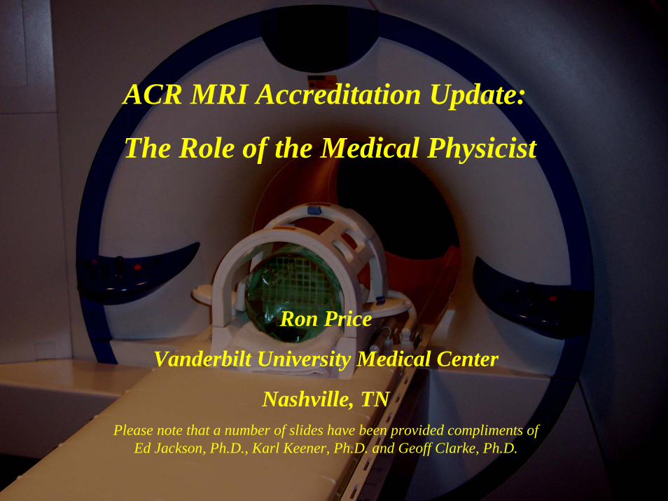
Ron Price
Vanderbilt University Medical Center
Nashville, TNPlease note that a number of slides have been provided compliments of
Ed Jackson, Ph.D., Karl Keener, Ph.D. and Geoff Clarke, Ph.D.
ACR MRI Accreditation Update:
The Role of the Medical Physicist
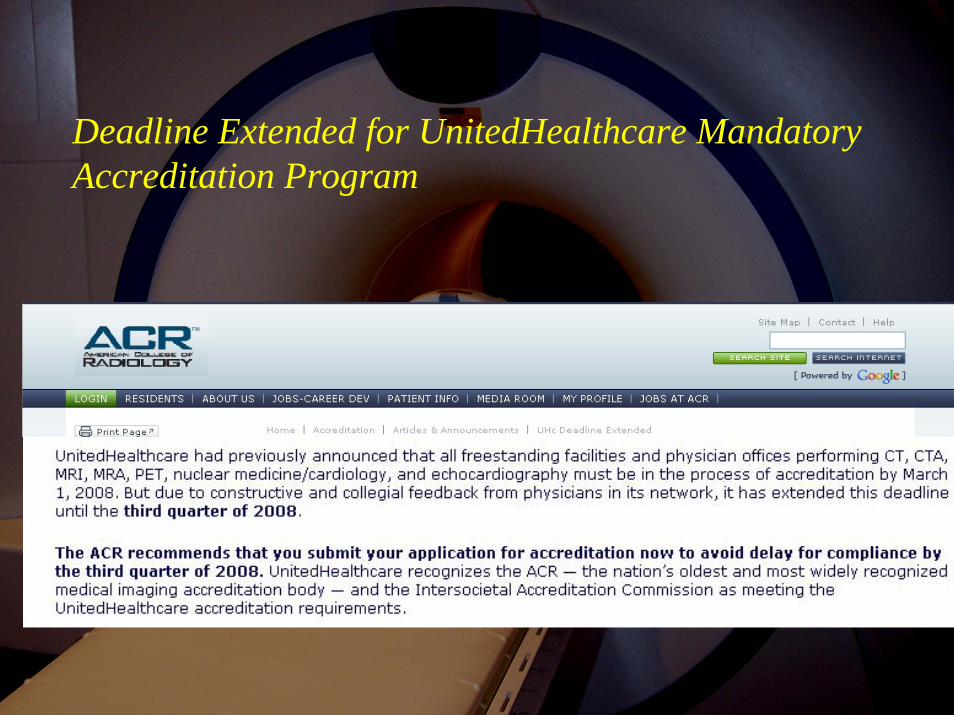
Deadline Extended for UnitedHealthcare Mandatory Accreditation Program
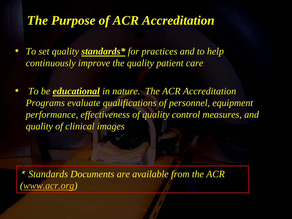
The Purpose of ACR AccreditationThe Purpose of ACR Accreditation
•• To set quality To set quality standards*standards* for practices and to help for practices and to help continuously improve the quality patient carecontinuously improve the quality patient care
•• To be To be educationaleducational in nature. The ACR Accreditation in nature. The ACR Accreditation Programs evaluate qualifications of personnel, equipment Programs evaluate qualifications of personnel, equipment performance, effectiveness of quality control measures, and performance, effectiveness of quality control measures, and quality of clinical imagesquality of clinical images
* Standards Documents are available from the ACR (www.acr.org)

ACR Specifications for Qualified Medical ACR Specifications for Qualified Medical Physicist/MR ScientistPhysicist/MR Scientist**
* ACR Technical Standard for Diagnostic Medical Physics Performance Monitoring of Magnetic Resonance Imaging (MRI) Equipment (effective 10/01/04)
“The American College of Radiology (ACR) considers certification and continuing education in the appropriate subfield(s) … to be a Qualified Medical Physicist.” The standard specifically identifies certification by ABR and ABMP.
“A Qualified MR Scientist is an individual who has obtained a graduate degree in a physical science involving nuclear MR or MRI. He or she should have 3 years of documented experience in a clinical MRI environment.”
“The continuing education of a Qualified Medical Physicist/MR Scientist should be in accordance with the ACR Practice Guideline for Continuing Medical Education (CME). (2006-ACR Resolution 16g)”(At least 15 CME hours in MRI in the prior 36-month period)
Responsibilities of the Qualified Medical Physicist/MR Scientist*
1. Acceptance Testing that is to be performed upon installation.
2. Assist in establishing a Quality Control Program that is continuous and implemented on all units. Determine frequency and who performs tests.
3. Perform an MRI Equipment Performance Evaluation at least annually and after major repair or system upgrade)
4. Provide Written Reports and Follow-up Procedures that are submitted to the responsible physician/personnel in a timely manner.
* ACR Technical Standard for Diagnostic Medical Physics Performance Monitoring of Magnetic Resonance Imaging (MRI) Equipment (Effective 10/01/04, Amended 2006)
(www.acr.org)
Medical Physicist/MR Scientist Responsibility1. Acceptance Testing:• Performed on ew systems before the first patient scan
• Following any major hardware or software upgrade
• Performed on existing systems not previously accredited
2. Quality Control Program:Assistance the QC Technologist to establish a weekly QC program by acquiring baseline QC data and defining action limits and appropriate corrective actions (response to out-of-range values) for:• Central frequency
• Transmitter gain/attenuation
• Geometric accuracy
• High-contrast spatial resolution
• Low-contrast detectability
• Laser camera operating levels and SMPTE analysis(in consultation with laser camera service engineer)
• and in general to assist in the development and performance of an ongoing “Continuous QC Program”
Technologist’s Continuous Quality Control Program
Technologist’s Weekly QC Tests Includes:
• Center Frequency and RF gain/attn. (phantom prescan)
• Table Positioning (phantom)
• Setup and Scanning (phantom)
• Geometric Accuracy (phantom image)
• High-Contrast Resolution (phantom image)
• Low-Contrast Resolution (phantom image)
• Artifact Analysis (phantom image)
• Film Quality Control (SMTE)
• Visual Checklist
3. MRI Equipment Performance Evaluation
Standard specifies at least annual checks of :
1. Physical and mechanical stability
2. Phase stability (ghosting)
3. Magnetic field homogeneity
4. Magnetic field gradient calibration
5. Radiofrequency (RF) calibration for all coils
6. Image signal-to-noise ratio (SNR) for all coils
7. Intensity uniformity for all volume coils
8. Slice thickness and location accuracy
9. Interslice RF Interference*
10. Spatial resolution and low contrast object detectability
10. Artifact evaluation
11. Film processor quality control (QC)
12. Hardcopy fidelity (SMTE)
13. Softcopy fidelity (monitor luminance)
14. Evaluation of MRI safety –environment and posting
* Scheduled for removal in 2009
Additional ACR MRI Accreditation Documents(www.acr.org)
- MRI Accreditation Program Requirements (revised 9/25/07)
- MRI Accreditation Program TESTING INSTRUCTIONS (revised 12/19/07)
- Site Scanning Instructions for Use of the MR Phantom for the ACR MRIAccreditation Program (12/02)
- Phantom Test Guidance (2005)
- Clinical Test Image Data Forms (one for each type of clinical exam)
- ACR Guidance Document for Safe MR Practices: 2007Kanal et al, American Journal of Radiology;188:1-27

Coming Soon: ACR Modular MRI Accreditation Program
• Anticipated in 2008-2009
• Will be similar to CT program and will closely reflect the clinical use of each machine
• Proposed modules: 1) Head/Neck 4) Body 7) Orthopedic*
2) Spine 5) MRA 8) Breast**3) MSK 6) Cardiac
• Each unit must undergo testing in the appropriate module(s)
** Note: Breast MRI Accreditation will be through the ACR Mammography Program
Currently Active ACR MRI Accreditation Modules• Whole Body
• Cardiac
*Specialty magnets
ACR Accreditation Process Overview:The accreditation process consists of two phases:
Phase 1: “Entry Application” (available online)Essentially to request a Testing Material Packet for the Full Application
Entry Application requires:
• Contact information (supervising physician and contact technologist)
• Information regarding the installed magnet(s) and clinical practice
• Credentials for physicians, technologists, medical physicist/MR scientist
• Date of last physics performance survey and evidence of a peer review program
• Payment information ($2400 for first magnet, $2300 for each subsequent magnet)
Phase 2: “Full Application”You will then receive a Testing Material Packet for the Full Application
The Full Application requires:
• Phantom and Clinical Images
• Performance report for each magnet (< 1 year) and last quarter QC documents
Does the ACR require that a physicist/MR scientist perform testing services for a facility to apply for accreditation?
No, however, sites usually appreciate the help of the medical physicist in both phases of the application process and ...
“Starting July 1, 2005, sites applying for MRI accreditation mustsubmit an annual MRI system performance evaluation performed by a medical physicist/MR scientist. A technologist may still perform the ACR phantom portion of the accreditation submission,although the ACR strongly recommends the services of a medical physicist or MR scientist for this also.”
Who makes the measurements?
The Full Application Testing Materials Packet Contains:1. The Testing Instuctions Document
2. Quality Assurance Questionnaire
3. Phantom order form ($730)
4. Site Scanning Instructions for the MR Phantom (how to make measurements)
5. Phantom Test Guidance booklet (how to check the measurements)
6. Clinical Test Image Data Forms* (one for each clinical exam)
7. Identification labels for images** (CD and film), forms and QC data
8. MRI Quality Control Manual
9. Laser Printer Attestation form (sites that indicated no filming on application)
* Clinical and Phantom images should be taken within a 2 week window
** Labels will have due dates for all forms and images (~90 days)
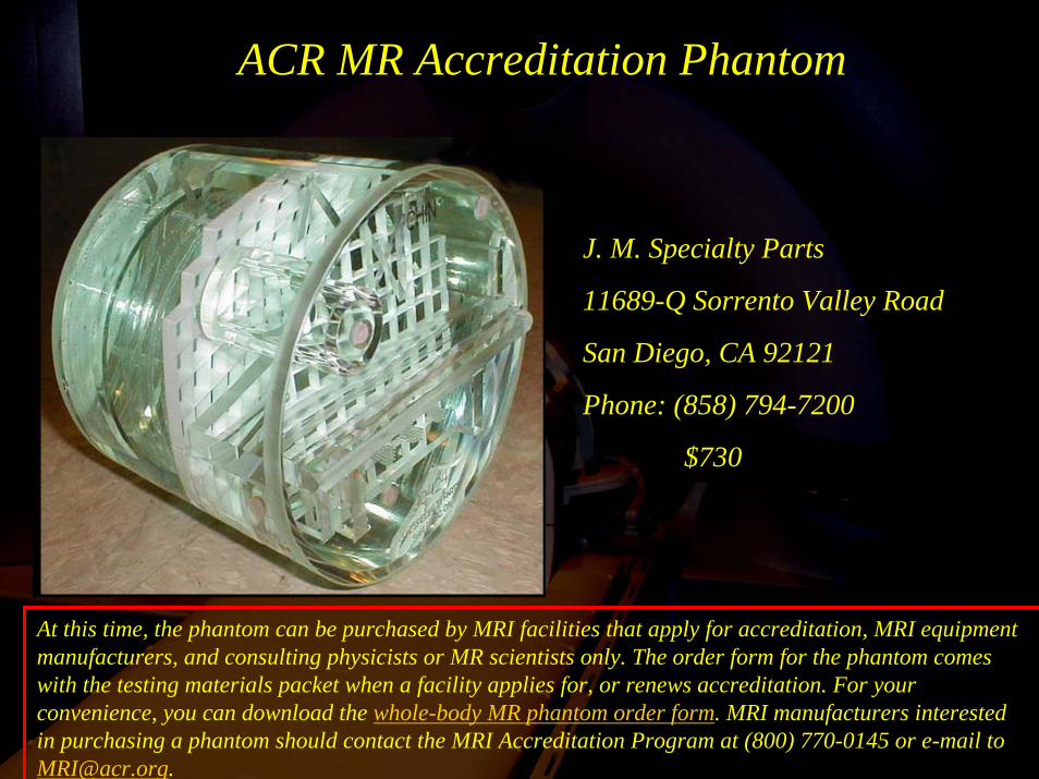
ACR MR Accreditation Phantom
At this time, the phantom can be purchased by MRI facilities that apply for accreditation, MRI equipment manufacturers, and consulting physicists or MR scientists only. The order form for the phantom comes with the testing materials packet when a facility applies for, or renews accreditation. For your convenience, you can download the whole-body MR phantom order form. MRI manufacturers interested in purchasing a phantom should contact the MRI Accreditation Program at (800) 770-0145 or e-mail to [email protected].
J. M. Specialty Parts
11689-Q Sorrento Valley Road
San Diego, CA 92121
Phone: (858) 794-7200
$730
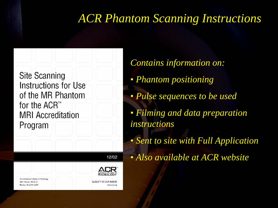
ACR Phantom Scanning Instructions
Contains information on:
• Phantom positioning
• Pulse sequences to be used
• Filming and data preparation instructions
• Sent to site with Full Application
• Also available at ACR website
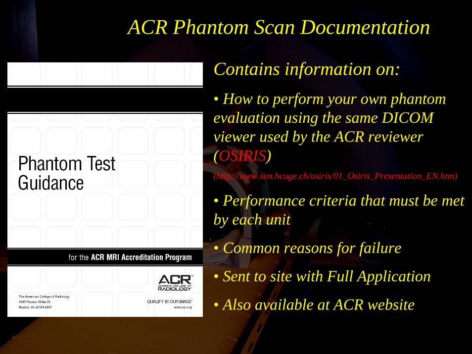
ACR Phantom Scan Documentation
Contains information on:• How to perform your own phantom evaluation using the same DICOM viewer used by the ACR reviewer (OSIRIS)(http://www.sim.hcuge.ch/osiris/01_Osiris_Presentation_EN.htm)
• Performance criteria that must be met by each unit
• Common reasons for failure
• Sent to site with Full Application
• Also available at ACR website
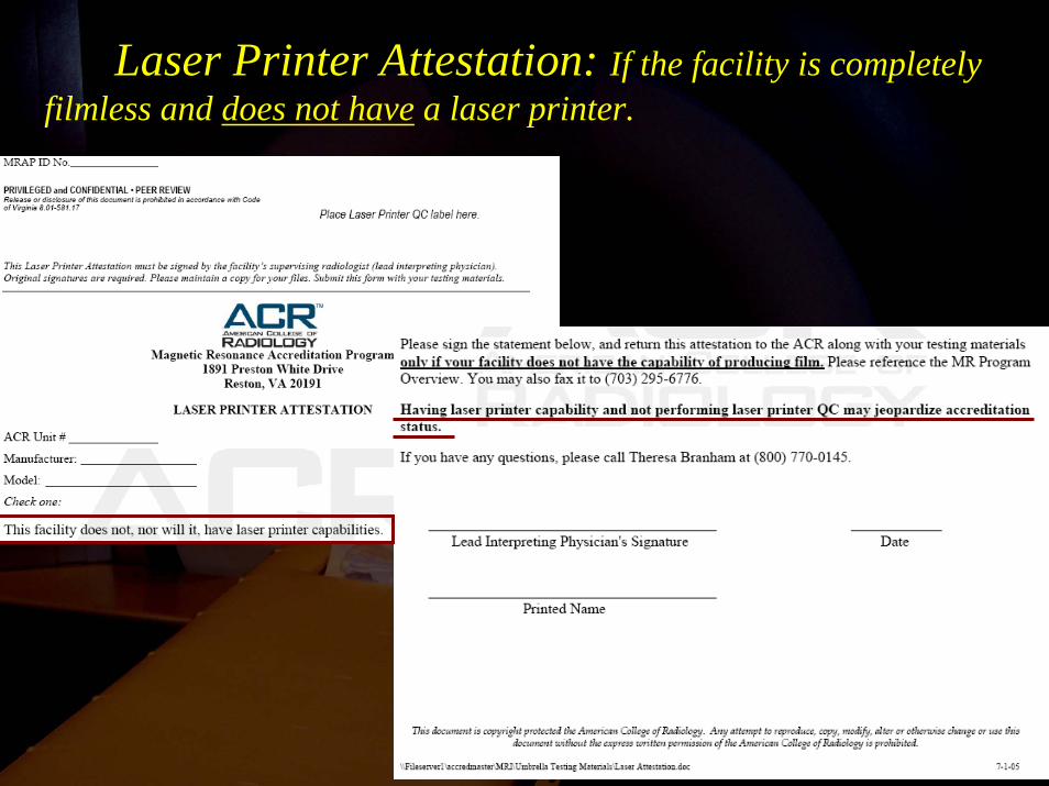
Laser Printer Attestation: If the facility is completely filmless and does not have a laser printer.
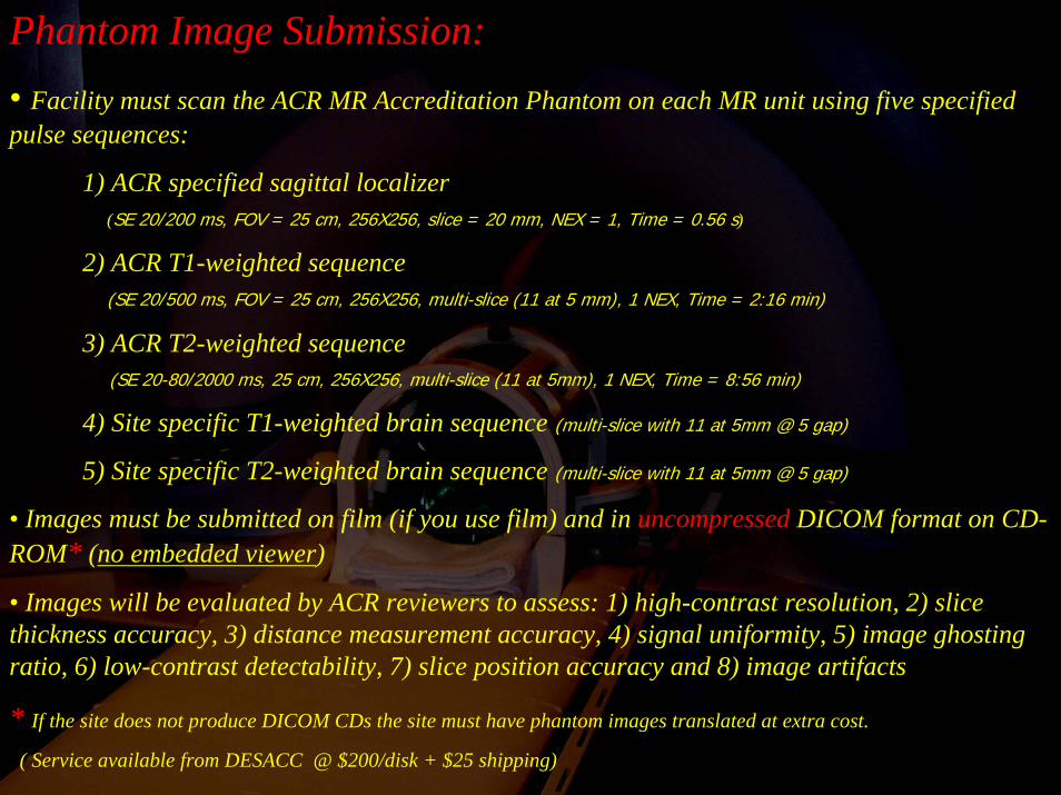
Phantom Image Submission:• Facility must scan the ACR MR Accreditation Phantom on each MR unit using five specified pulse sequences:
1) ACR specified sagittal localizer(SE 20/200 ms, FOV = 25 cm, 256X256, slice = 20 mm, NEX = 1, Time = 0.56 s)
2) ACR T1-weighted sequence(SE 20/500 ms, FOV = 25 cm, 256X256, multi-slice (11 at 5 mm), 1 NEX, Time = 2:16 min)
3) ACR T2-weighted sequence (SE 20-80/2000 ms, 25 cm, 256X256, multi-slice (11 at 5mm), 1 NEX, Time = 8:56 min)
4) Site specific T1-weighted brain sequence (multi-slice with 11 at 5mm @ 5 gap)
5) Site specific T2-weighted brain sequence (multi-slice with 11 at 5mm @ 5 gap)
• Images must be submitted on film (if you use film) and in uncompressed DICOM format on CD-ROM* (no embedded viewer)
• Images will be evaluated by ACR reviewers to assess: 1) high-contrast resolution, 2) slice thickness accuracy, 3) distance measurement accuracy, 4) signal uniformity, 5) image ghosting ratio, 6) low-contrast detectability, 7) slice position accuracy and 8) image artifacts
* If the site does not produce DICOM CDs the site must have phantom images translated at extra cost.
( Service available from DESACC @ $200/disk + $25 shipping)
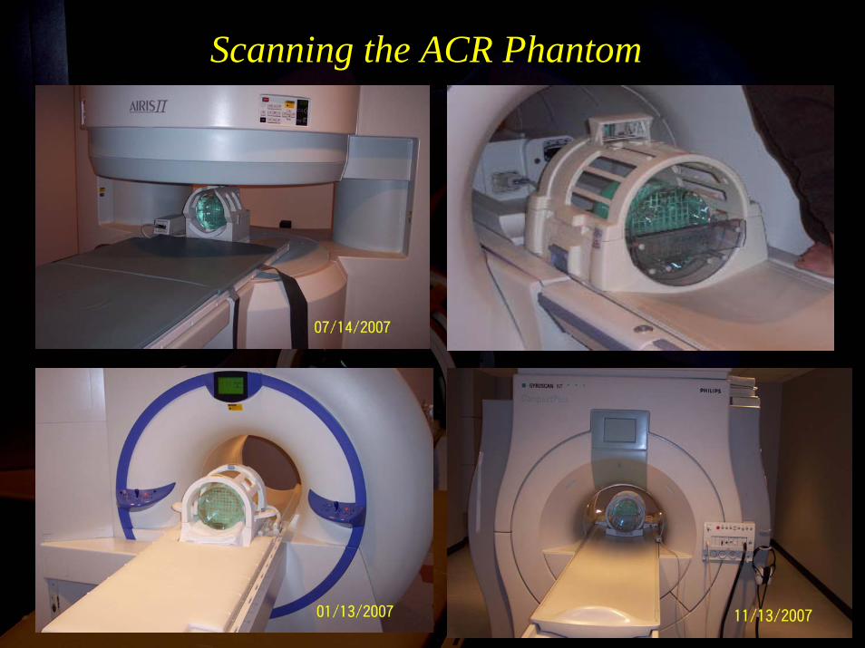
Scanning the ACR Phantom
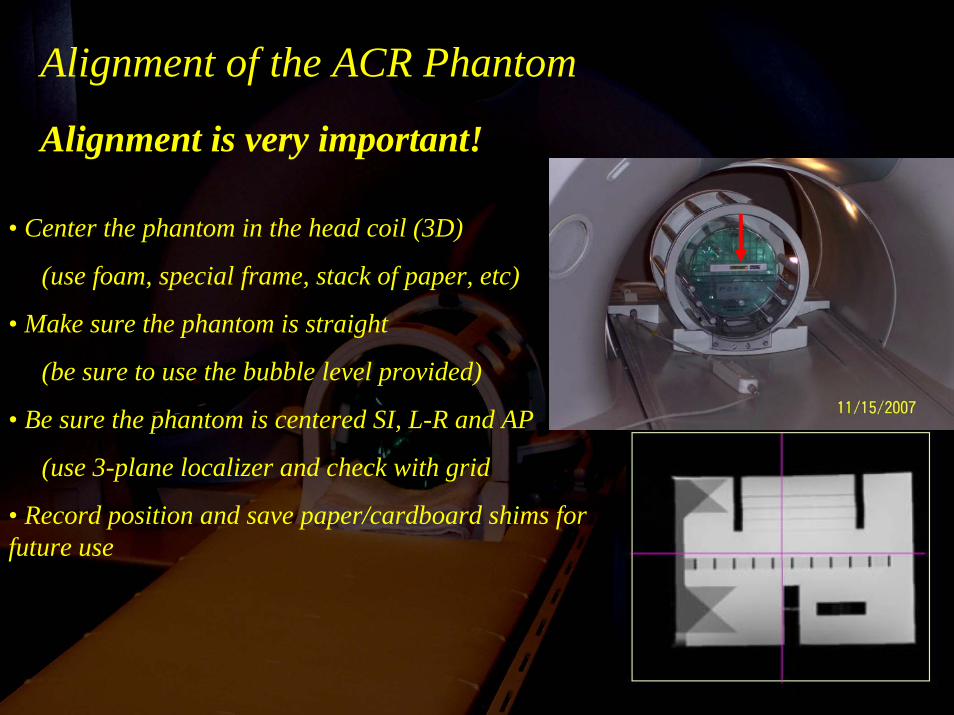
Alignment of the ACR Phantom
Alignment is very important!
• Center the phantom in the head coil (3D)
(use foam, special frame, stack of paper, etc)
• Make sure the phantom is straight
(be sure to use the bubble level provided)
• Be sure the phantom is centered SI, L-R and AP
(use 3-plane localizer and check with grid
• Record position and save paper/cardboard shims for future use
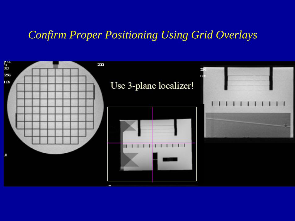
Confirm Proper Positioning Using Grid Overlays
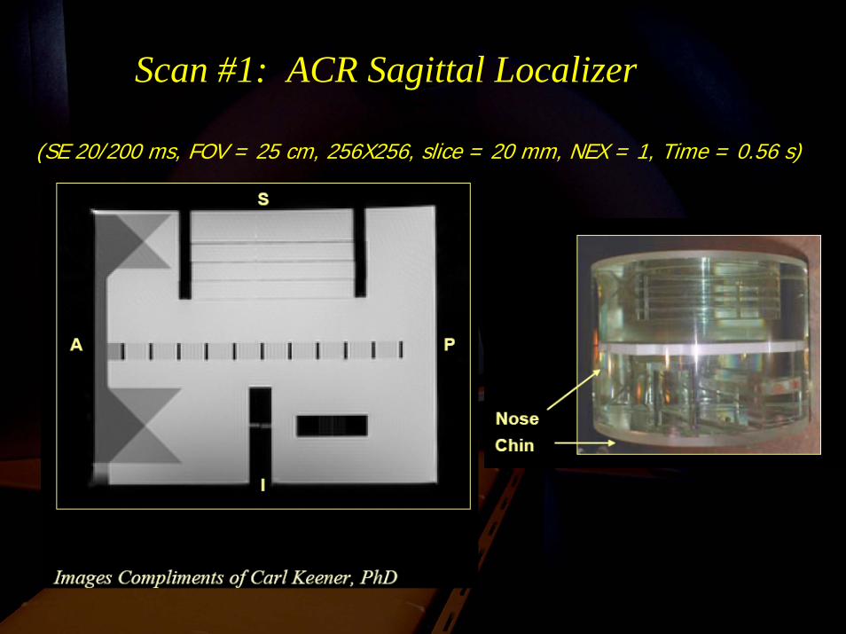
Scan #1: ACR Sagittal Localizer
(SE 20/200 ms, FOV = 25 cm, 256X256, slice = 20 mm, NEX = 1, Time = 0.56 s)
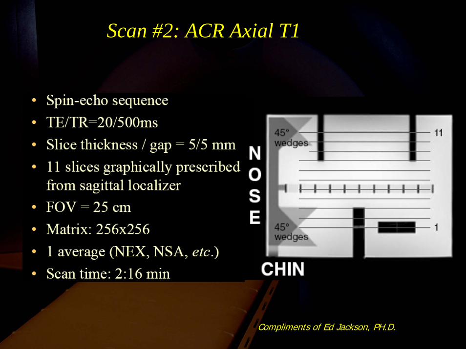
Scan #2: ACR Axial T1
Compliments of Ed Jackson, PH.D.
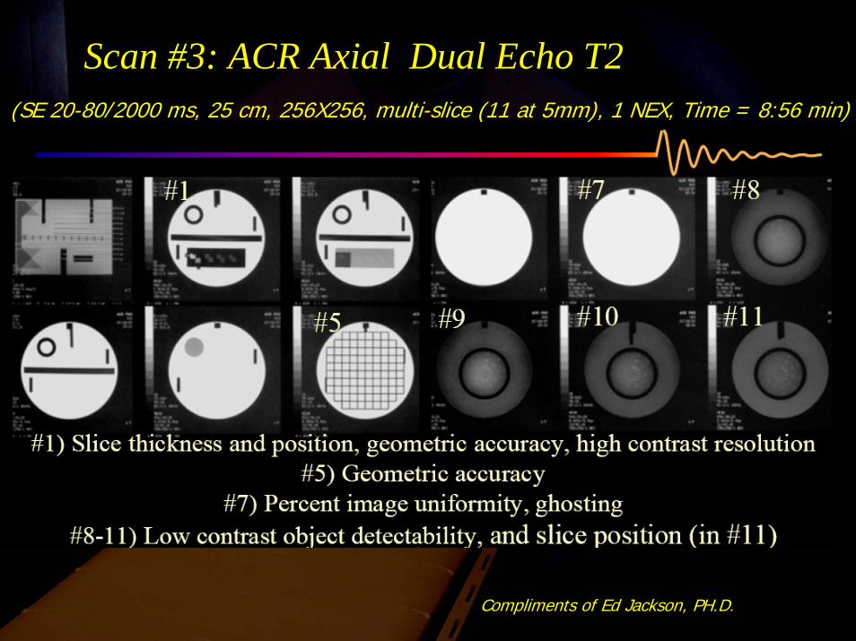
Scan #3: ACR Axial Dual Echo T2
Compliments of Ed Jackson, PH.D.
(SE 20-80/2000 ms, 25 cm, 256X256, multi-slice (11 at 5mm), 1 NEX, Time = 8:56 min)
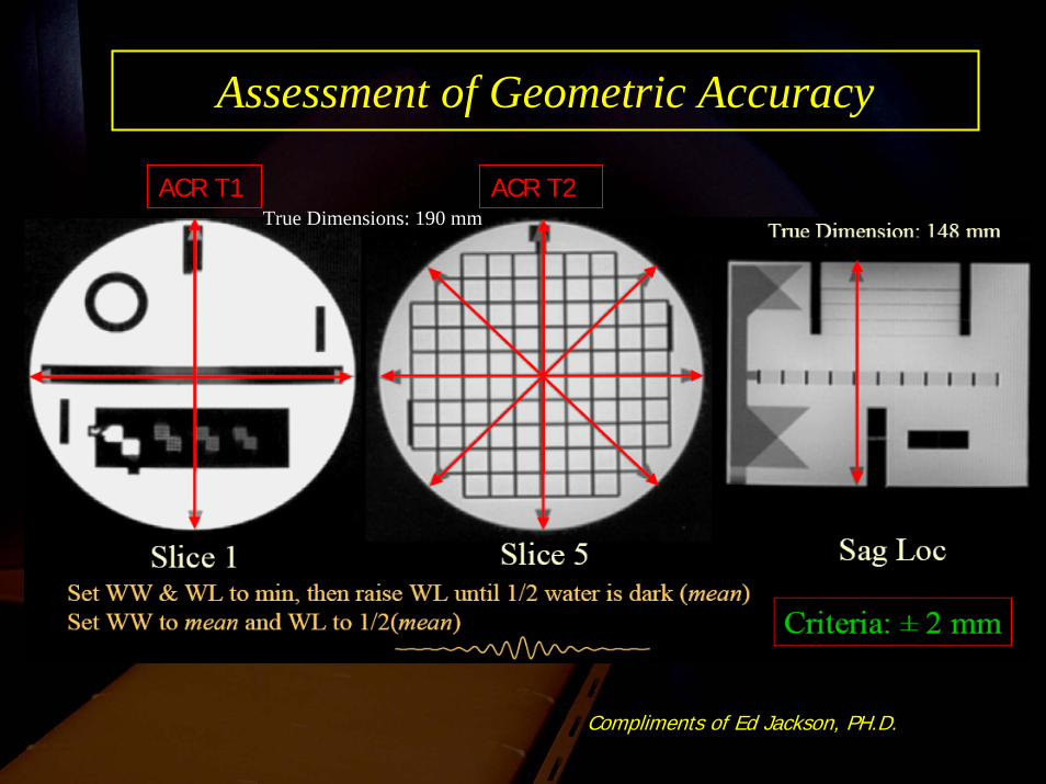
Assessment of Geometric Accuracy
Compliments of Ed Jackson, PH.D.
ACR T1 ACR T2True Dimensions: 190 mm
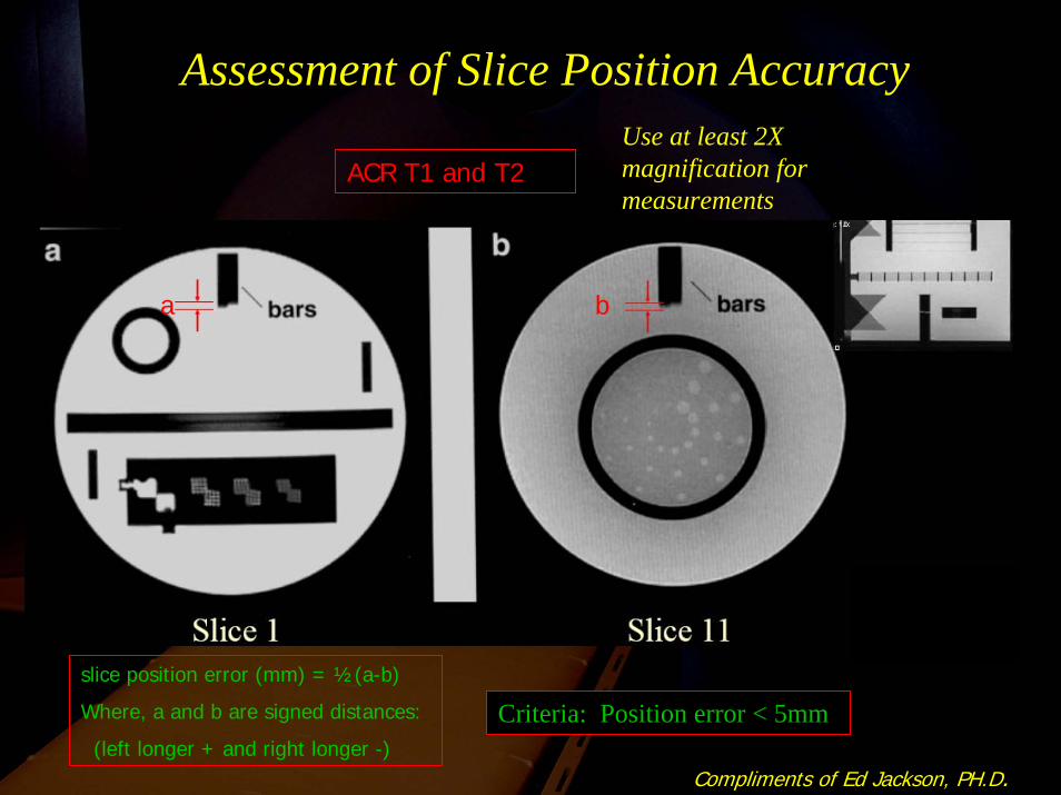
Assessment of Slice Position Accuracy
Criteria: Position error < 5mm
Compliments of Ed Jackson, PH.D.
ACR T1 and T2
slice position error (mm) = ½(a-b)
Where, a and b are signed distances:
(left longer + and right longer -)
a b
Use at least 2X magnification for measurements
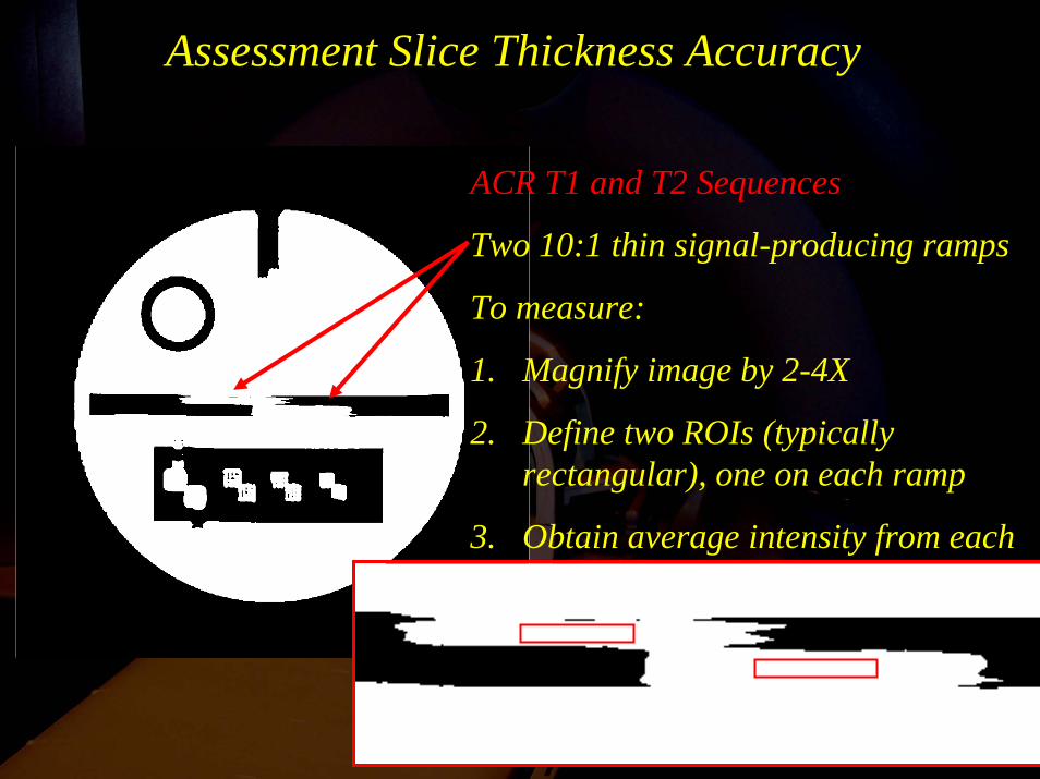
Assessment Slice Thickness Accuracy
ACR T1 and T2 Sequences
Two 10:1 thin signal-producing ramps
To measure:
1. Magnify image by 2-4X
2. Define two ROIs (typically rectangular), one on each ramp
3. Obtain average intensity from each of the two ROIs.
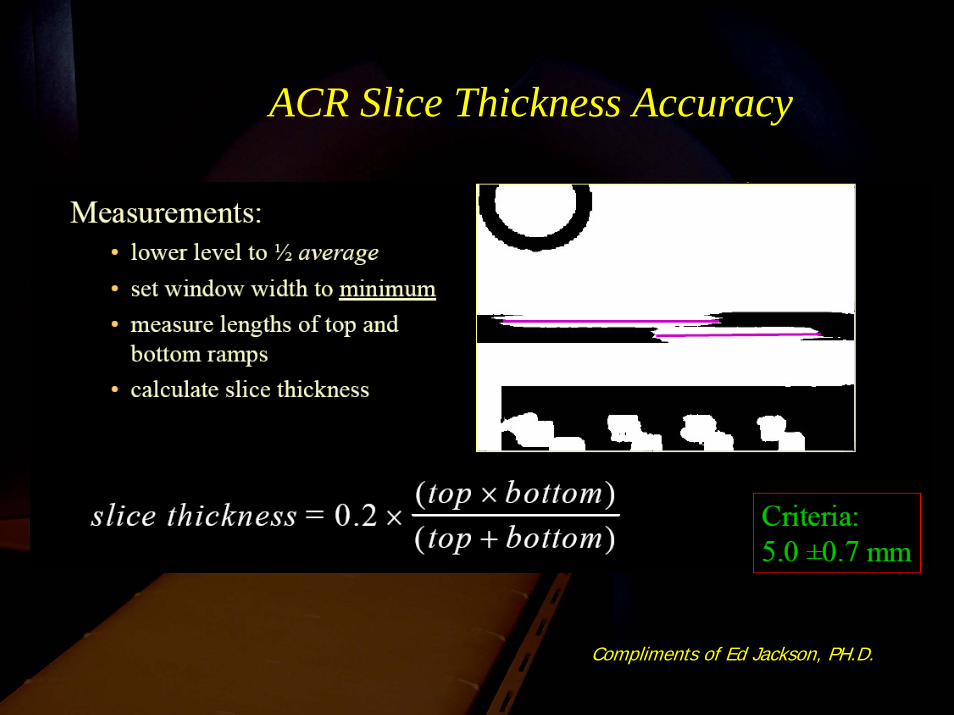
ACR Slice Thickness Accuracy
Compliments of Ed Jackson, PH.D.
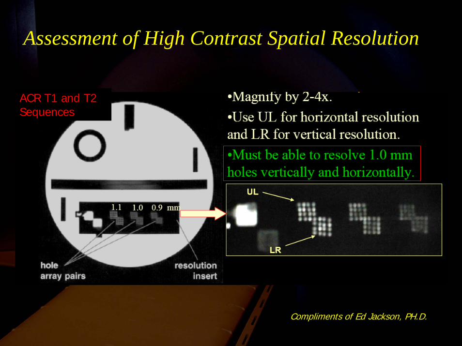
Assessment of High Contrast Spatial Resolution
ACR T1 and T2 Sequences
Compliments of Ed Jackson, PH.D.
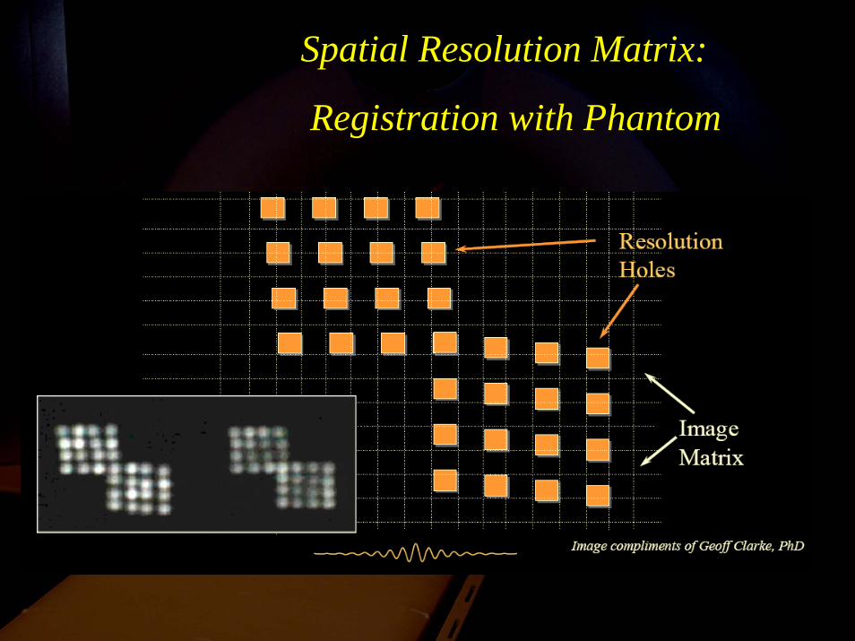
Spatial Resolution Matrix:
Registration with Phantom
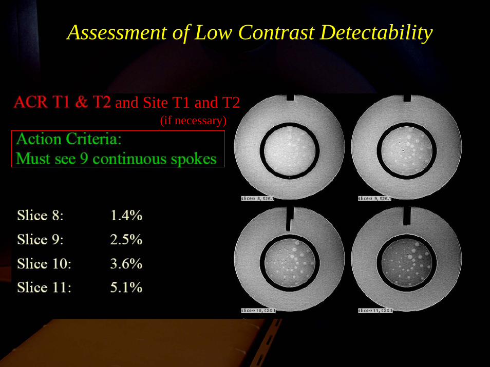
Assessment of Low Contrast Detectability
and Site T1 and T2(if necessary)
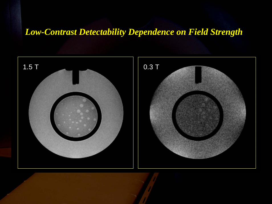
Low-Contrast Detectability Dependence on Field Strength
1.5 T 0.3 T
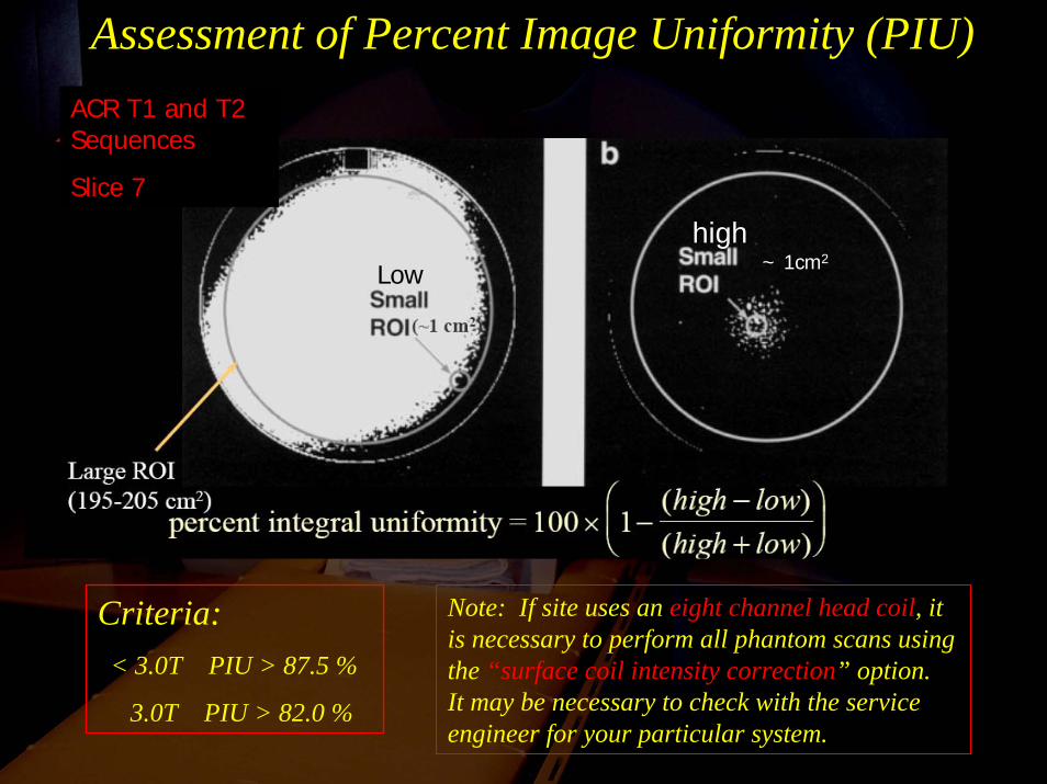
Assessment of Percent Image Uniformity (PIU)
Criteria:< 3.0T PIU > 87.5 %
3.0T PIU > 82.0 %
Note: If site uses an eight channel head coil, it is necessary to perform all phantom scans using the “surface coil intensity correction” option. It may be necessary to check with the service engineer for your particular system.
ACR T1 and T2 Sequences
Slice 7
~ 1cm2
highLow
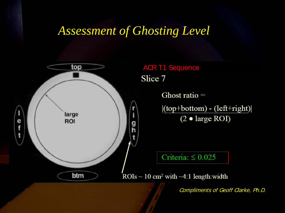
Assessment of Ghosting Level
ACR T1 Sequence
Compliments of Geoff Clarke, Ph.D.
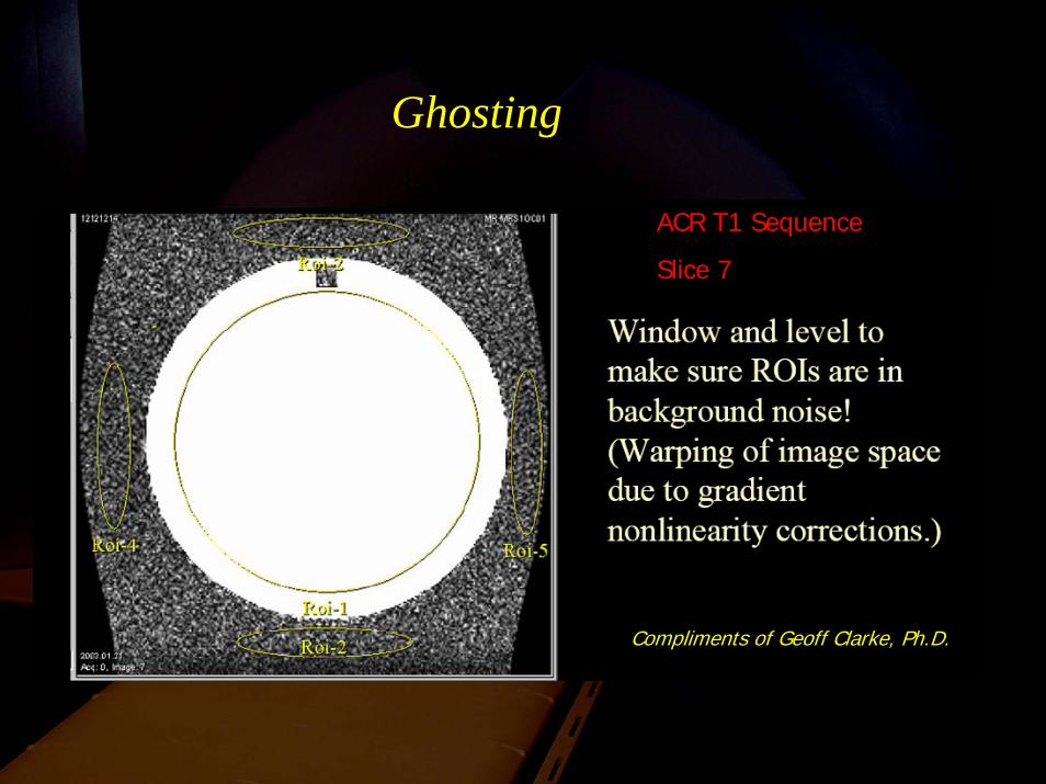
Ghosting
ACR T1 Sequence
Slice 7
Compliments of Geoff Clarke, Ph.D.
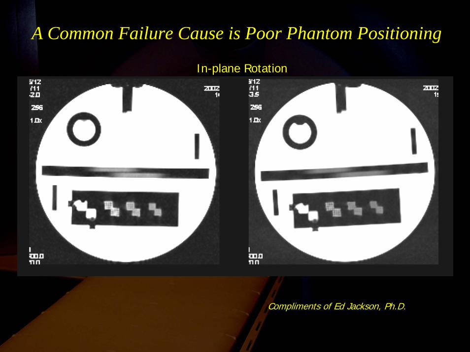
A Common Failure Cause is Poor Phantom Positioning
Compliments of Ed Jackson, Ph.D.
In-plane Rotation
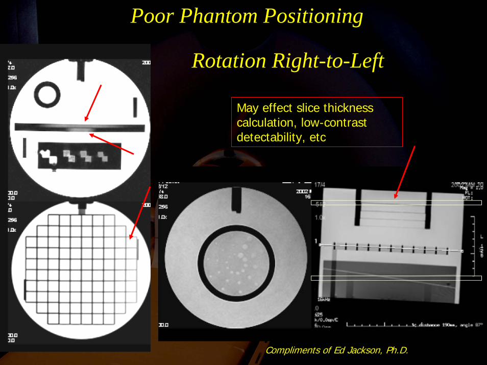
Poor Phantom Positioning
Rotation Right-to-Left
Compliments of Ed Jackson, Ph.D.
May effect slice thickness calculation, low-contrast detectability, etc
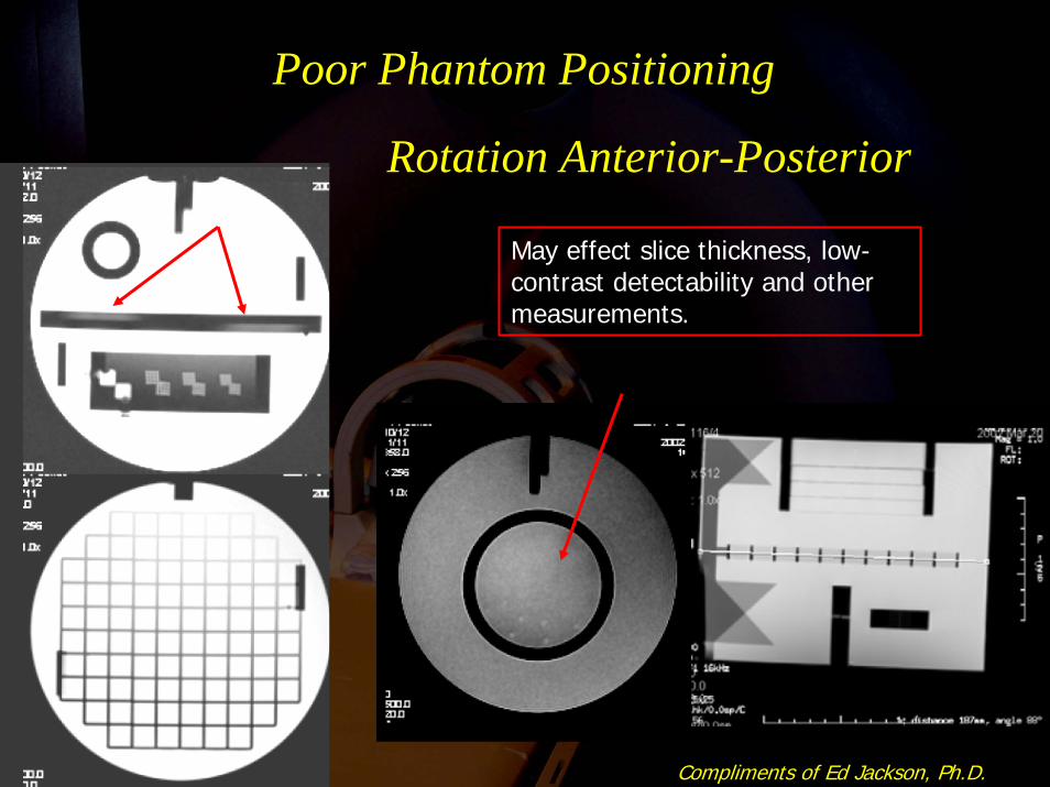
Rotation Anterior-Posterior
Poor Phantom Positioning
Compliments of Ed Jackson, Ph.D.
May effect slice thickness, low-contrast detectability and other measurements.
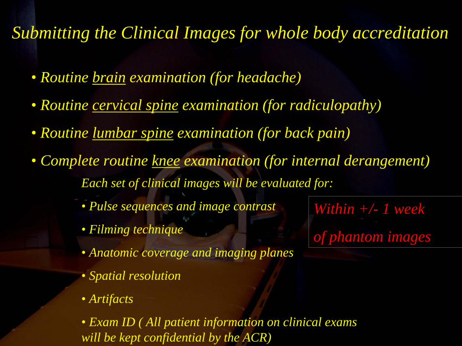
Submitting the Clinical Images for whole body accreditation
• Routine brain examination (for headache)
• Routine cervical spine examination (for radiculopathy)
• Routine lumbar spine examination (for back pain)
• Complete routine knee examination (for internal derangement)Each set of clinical images will be evaluated for:
• Pulse sequences and image contrast
• Filming technique
• Anatomic coverage and imaging planes
• Spatial resolution
• Artifacts
• Exam ID ( All patient information on clinical exams will be kept confidential by the ACR)
Within +/- 1 week
of phantom images
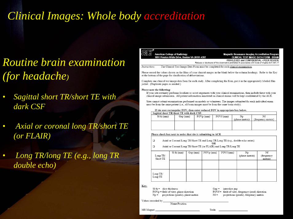
Clinical Images: Whole body accreditation
Routine brain examination (for headache)
• Sagittal short TR/short TE with dark CSF
• Axial or coronal long TR/short TE (or FLAIR)
• Long TR/long TE (e.g., long TR double echo)
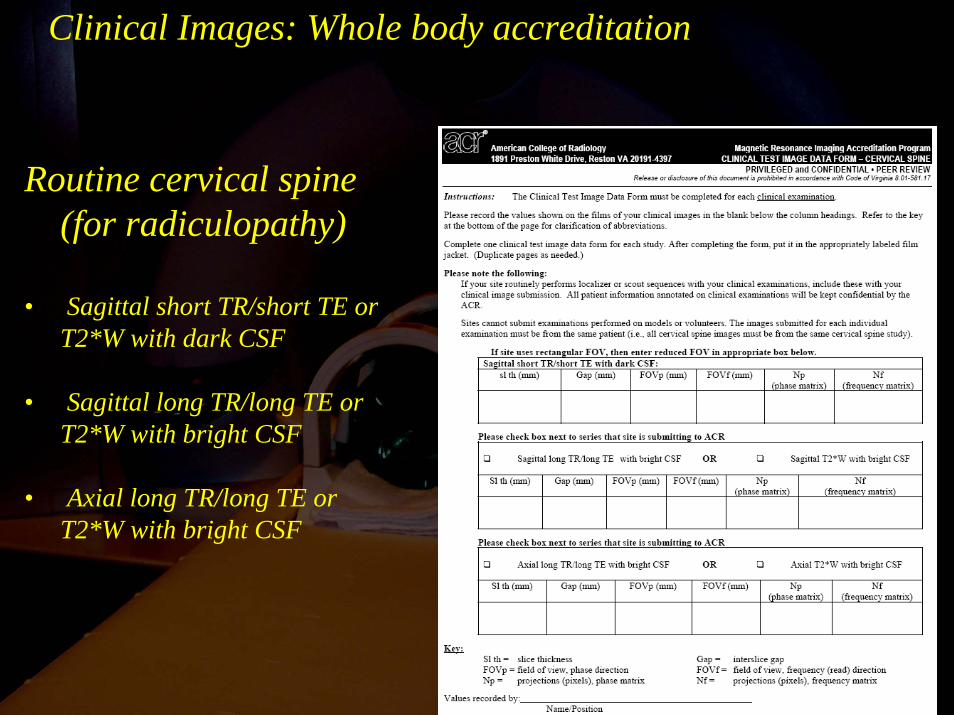
Routine cervical spine (for radiculopathy)
• Sagittal short TR/short TE or T2*W with dark CSF
• Sagittal long TR/long TE or T2*W with bright CSF
• Axial long TR/long TE or T2*W with bright CSF
Clinical Images: Whole body accreditation
Clinical Images: Whole Body Accreditation
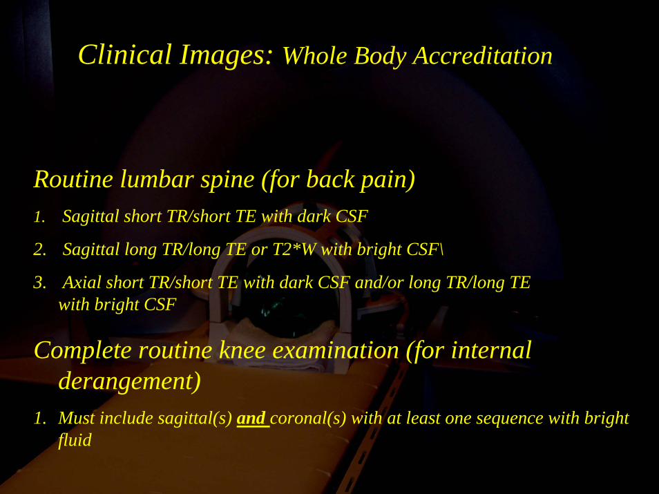
Routine lumbar spine (for back pain)1. Sagittal short TR/short TE with dark CSF
2. Sagittal long TR/long TE or T2*W with bright CSF\
3. Axial short TR/short TE with dark CSF and/or long TR/long TE with bright CSF
Complete routine knee examination (for internal derangement)
1. Must include sagittal(s) and coronal(s) with at least one sequence with bright fluid
Clinical Images: Submission Options
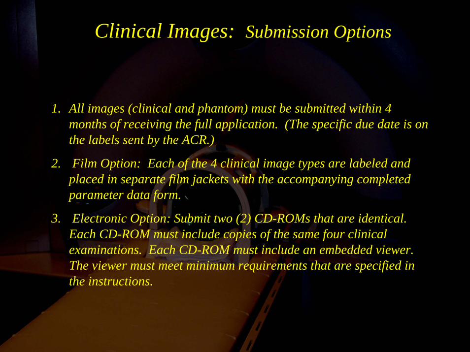
1. All images (clinical and phantom) must be submitted within 4 months of receiving the full application. (The specific due date is on the labels sent by the ACR.)
2. Film Option: Each of the 4 clinical image types are labeled and placed in separate film jackets with the accompanying completed parameter data form.
3. Electronic Option: Submit two (2) CD-ROMs that are identical. Each CD-ROM must include copies of the same four clinical examinations. Each CD-ROM must include an embedded viewer. The viewer must meet minimum requirements that are specified in the instructions.
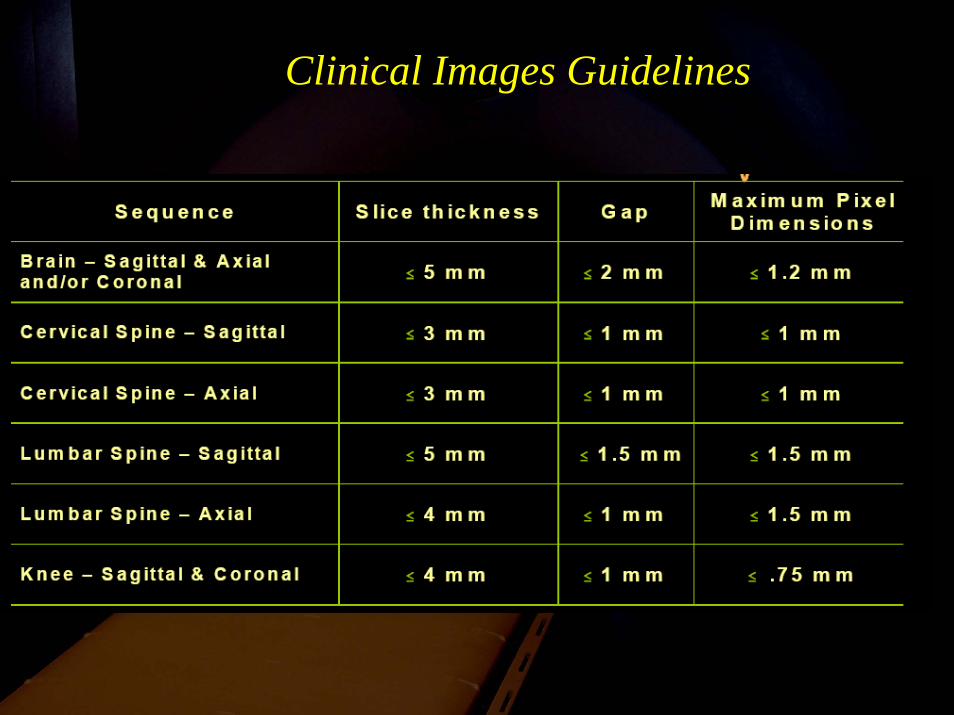
Clinical Images Guidelines
Accreditation Program Statistics
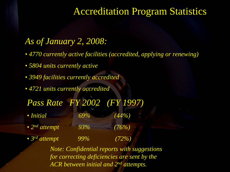
As of January 2, 2008:• 4770 currently active facilities (accredited, applying or renewing)
• 5804 units currently active
• 3949 facilities currently accredited
• 4721 units currently accredited
Pass Rate FY 2002 (FY 1997)• Initial 69% (44%)
• 2nd attempt 93% (76%)
• 3rd attempt 99% (72%)Note: Confidential reports with suggestions for correcting deficiencies are sent by the ACR between initial and 2nd attempts.
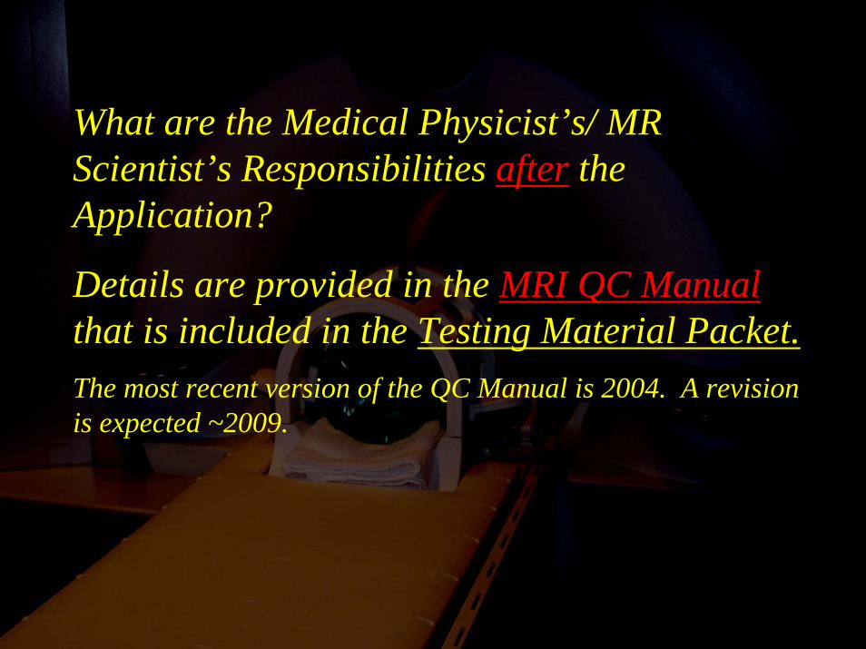
What are the Medical Physicist’s/ MR Scientist’s Responsibilities after the Application?
Details are provided in the MRI QC Manualthat is included in the Testing Material Packet.The most recent version of the QC Manual is 2004. A revision is expected ~2009.

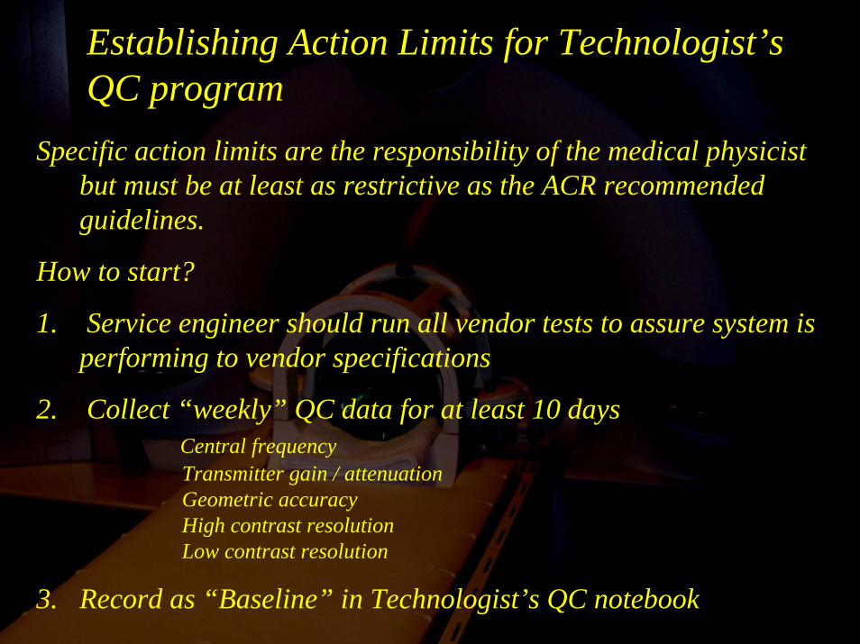
Establishing Action Limits for Technologist’s QC program
Specific action limits are the responsibility of the medical physicist but must be at least as restrictive as the ACR recommended guidelines.
How to start?
1. Service engineer should run all vendor tests to assure system is performing to vendor specifications
2. Collect “weekly” QC data for at least 10 daysCentral frequencyTransmitter gain / attenuationGeometric accuracyHigh contrast resolutionLow contrast resolution
3. Record as “Baseline” in Technologist’s QC notebook
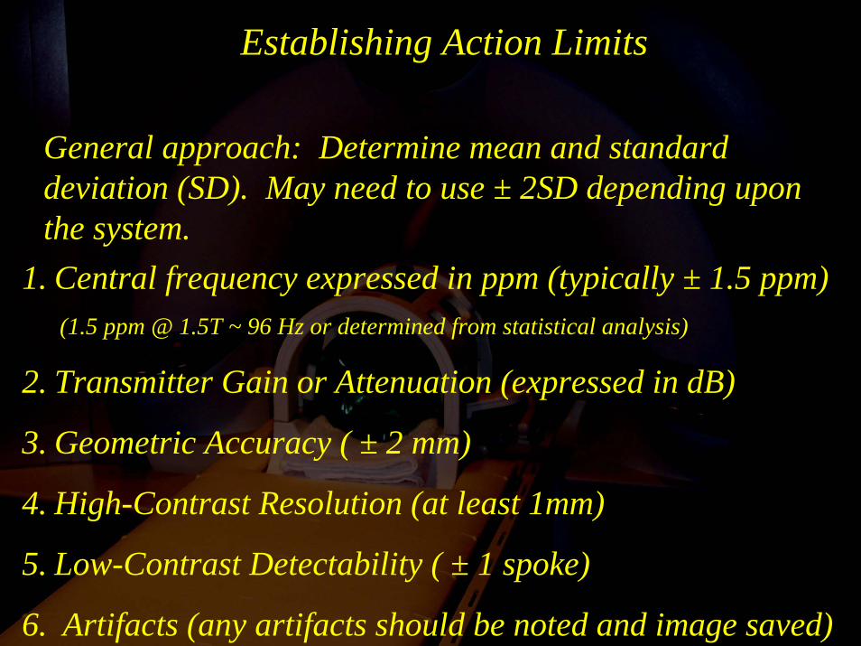
Establishing Action Limits
1. Central frequency expressed in ppm (typically ± 1.5 ppm)(1.5 ppm @ 1.5T ~ 96 Hz or determined from statistical analysis)
2. Transmitter Gain or Attenuation (expressed in dB)
3. Geometric Accuracy ( ± 2 mm)
4. High-Contrast Resolution (at least 1mm)
5. Low-Contrast Detectability ( ± 1 spoke)
6. Artifacts (any artifacts should be noted and image saved)
General approach: Determine mean and standard deviation (SD). May need to use ± 2SD depending upon the system.
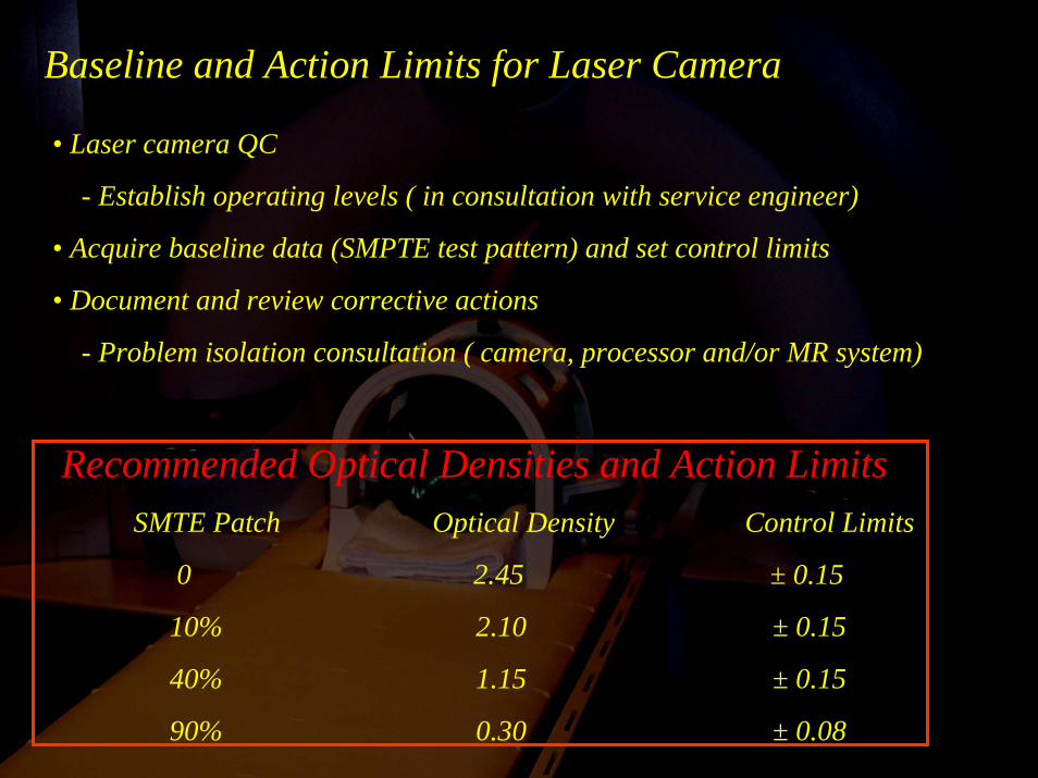
Baseline and Action Limits for Laser Camera
• Laser camera QC
- Establish operating levels ( in consultation with service engineer)
• Acquire baseline data (SMPTE test pattern) and set control limits
• Document and review corrective actions
- Problem isolation consultation ( camera, processor and/or MR system)
Recommended Optical Densities and Action LimitsSMTE Patch Optical Density Control Limits
0 2.45 ± 0.15
10% 2.10 ± 0.15
40% 1.15 ± 0.15
90% 0.30 ± 0.08
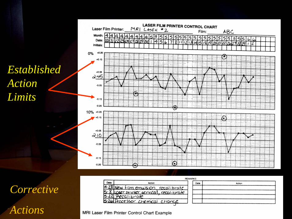
Established Action Limits
Corrective
Actions
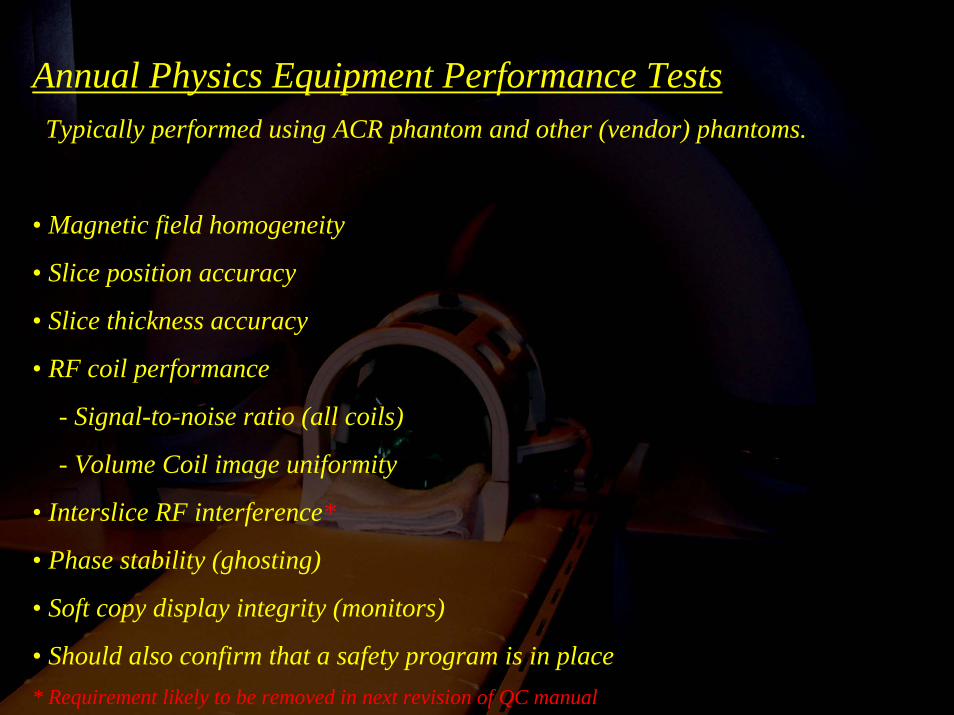
Annual Physics Equipment Performance TestsTypically performed using ACR phantom and other (vendor) phantoms.
• Magnetic field homogeneity
• Slice position accuracy
• Slice thickness accuracy
• RF coil performance
- Signal-to-noise ratio (all coils)
- Volume Coil image uniformity
• Interslice RF interference*
• Phase stability (ghosting)
• Soft copy display integrity (monitors)
• Should also confirm that a safety program is in place* Requirement likely to be removed in next revision of QC manual
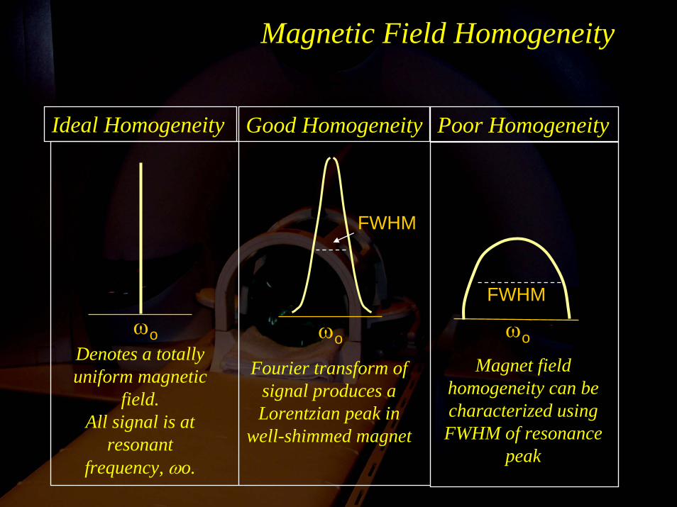
Magnetic Field Homogeneity
ωo ωo ωo
Fourier transform of signal produces a Lorentzian peak in
well-shimmed magnet
Magnet field homogeneity can be characterized using FWHM of resonance
peak
Denotes a totally uniform magnetic
field.All signal is at
resonant frequency, ωo.
Ideal Homogeneity Good Homogeneity Poor Homogeneity
FWHM
FWHM
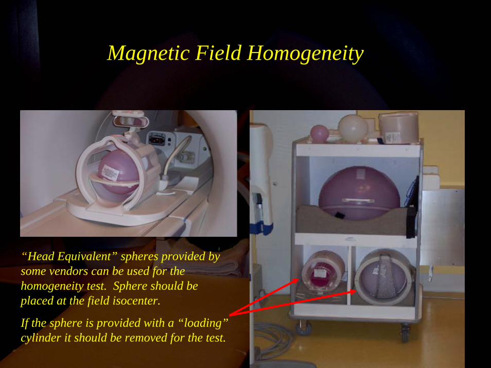
Magnetic Field Homogeneity
“Head Equivalent” spheres provided by some vendors can be used for the homogeneity test. Sphere should be placed at the field isocenter.
If the sphere is provided with a “loading”cylinder it should be removed for the test.
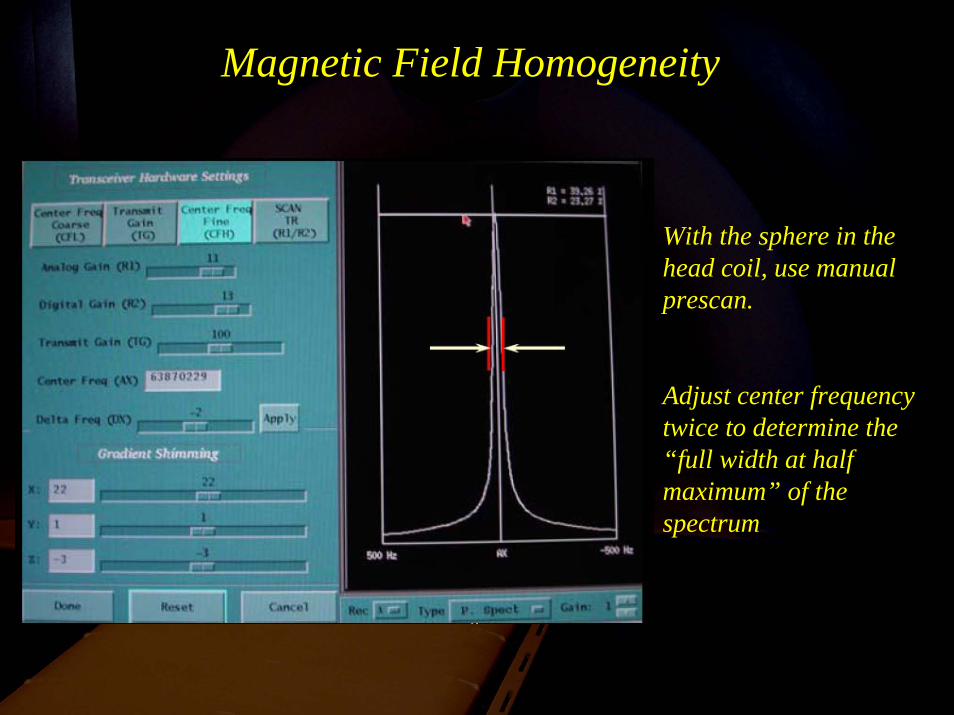
Magnetic Field Homogeneity
With the sphere in the head coil, use manual prescan.
Adjust center frequency twice to determine the “full width at half maximum” of the spectrum
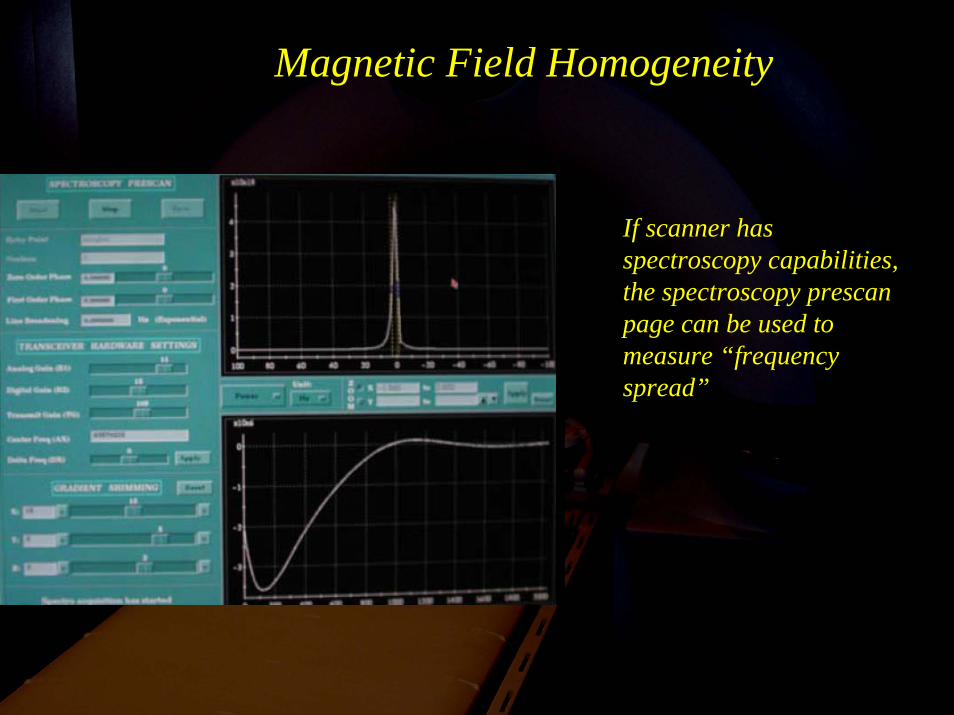
Magnetic Field Homogeneity
If scanner has spectroscopy capabilities, the spectroscopy prescanpage can be used to measure “frequency spread”
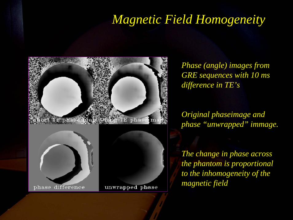
Magnetic Field Homogeneity
Phase (angle) images from GRE sequences with 10 ms difference in TE’s
Original phaseimage and phase “unwrapped” immage.
The change in phase across the phantom is proportional to the inhomogeneity of the magnetic field
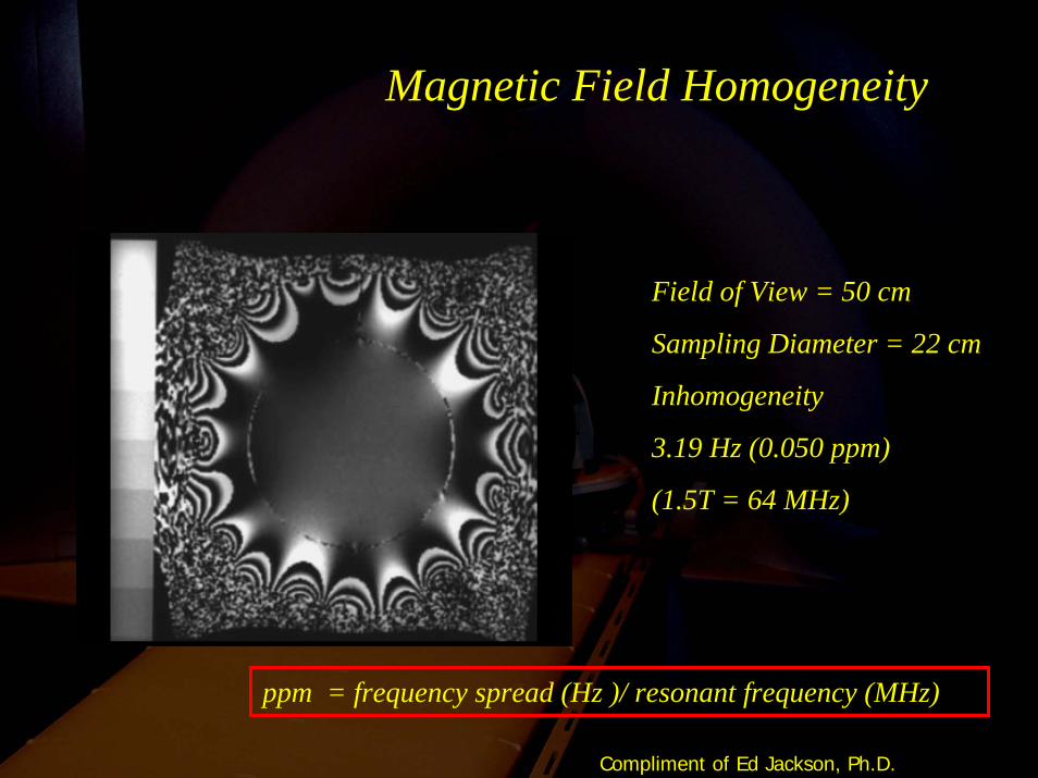
Magnetic Field Homogeneity
Field of View = 50 cm
Sampling Diameter = 22 cm
Inhomogeneity
3.19 Hz (0.050 ppm)
(1.5T = 64 MHz)
ppm = frequency spread (Hz )/ resonant frequency (MHz)
Compliment of Ed Jackson, Ph.D.
Magnetic Field Homogeneity
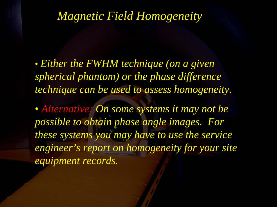
• Either the FWHM technique (on a given spherical phantom) or the phase difference technique can be used to assess homogeneity.
• Alternative: On some systems it may not be possible to obtain phase angle images. For these systems you may have to use the service engineer’s report on homogeneity for your site equipment records.
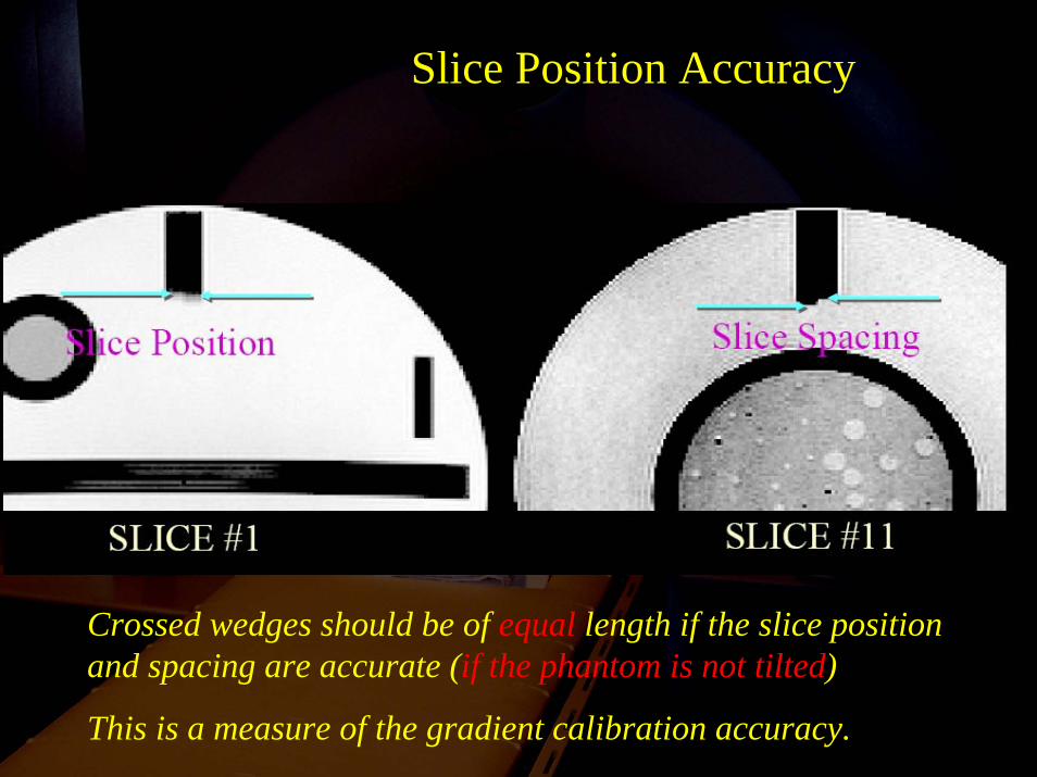
Slice Position Accuracy
Crossed wedges should be of equal length if the slice position and spacing are accurate (if the phantom is not tilted)
This is a measure of the gradient calibration accuracy.
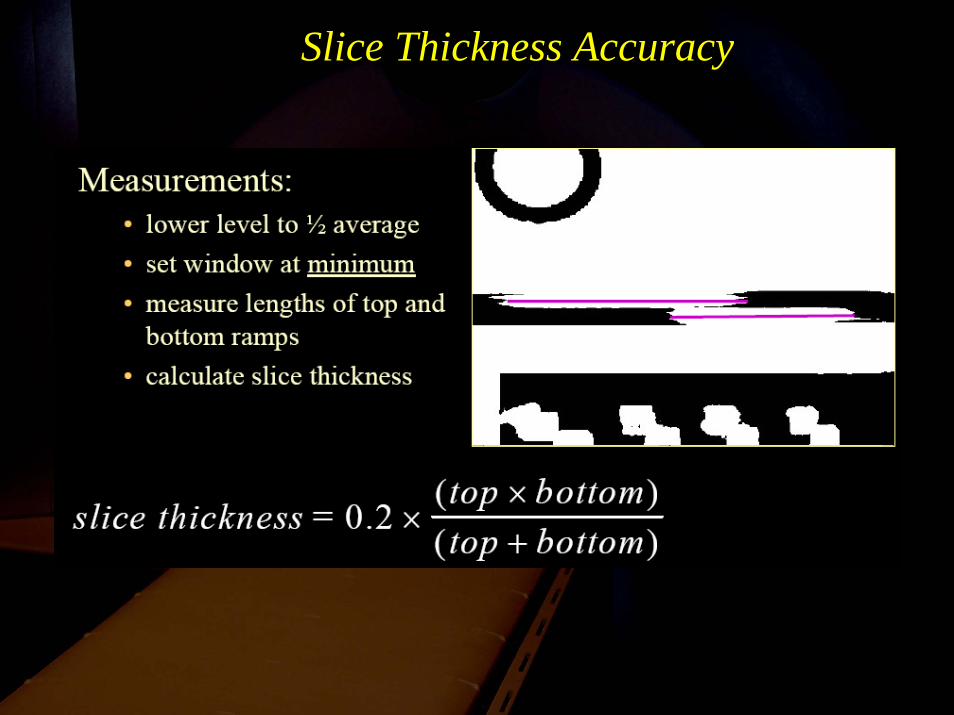
Slice Thickness Accuracy
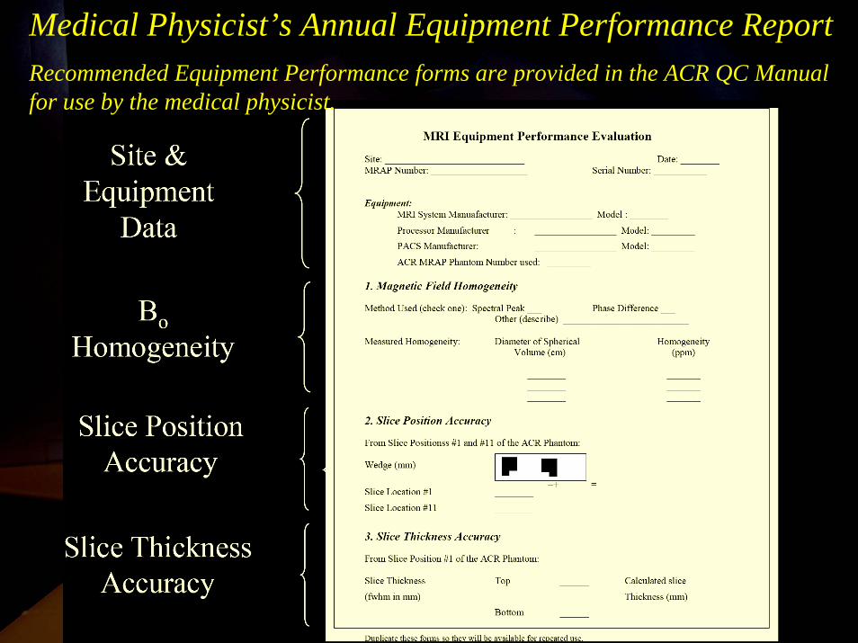
Medical Physicist’s Annual Equipment Performance ReportRecommended Equipment Performance forms are provided in the ACR QC Manual for use by the medical physicist.
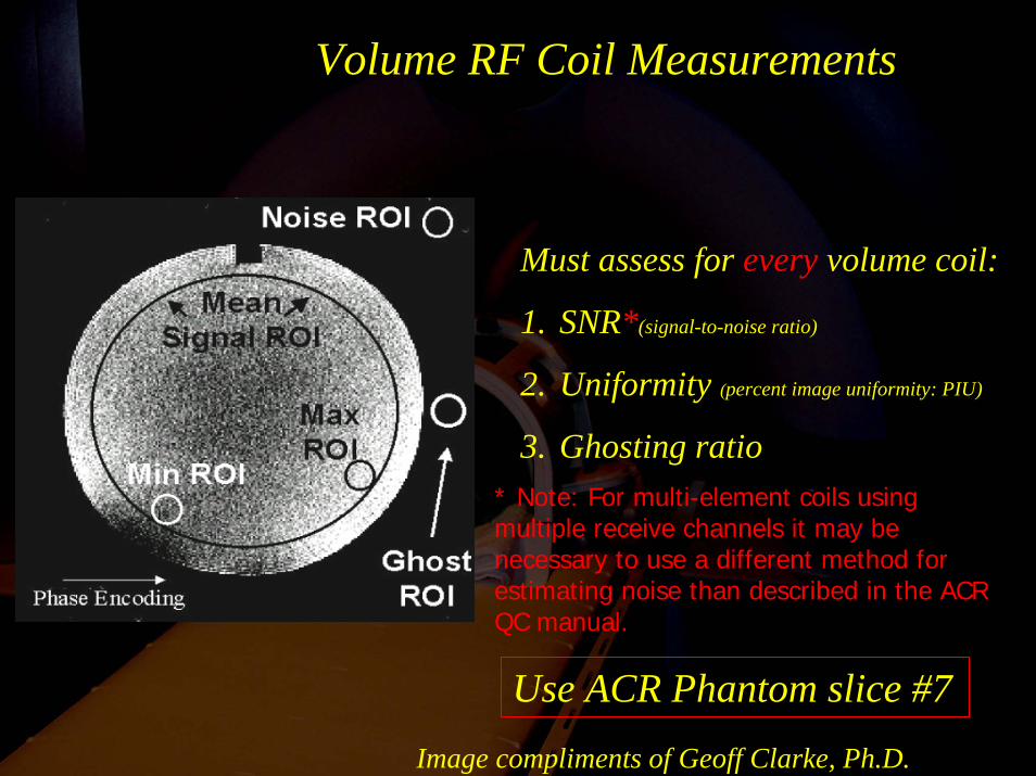
Volume RF Coil Measurements
Must assess for every volume coil:
1. SNR*(signal-to-noise ratio)
2. Uniformity (percent image uniformity: PIU)
3. Ghosting ratio
Use ACR Phantom slice #7Image compliments of Geoff Clarke, Ph.D.
* Note: For multi-element coils using multiple receive channels it may be necessary to use a different method for estimating noise than described in the ACR QC manual.
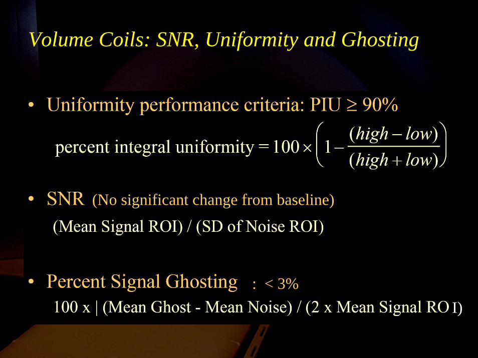
Volume Coils: SNR, Uniformity and Ghosting
I)
(No significant change from baseline)
: < 3%
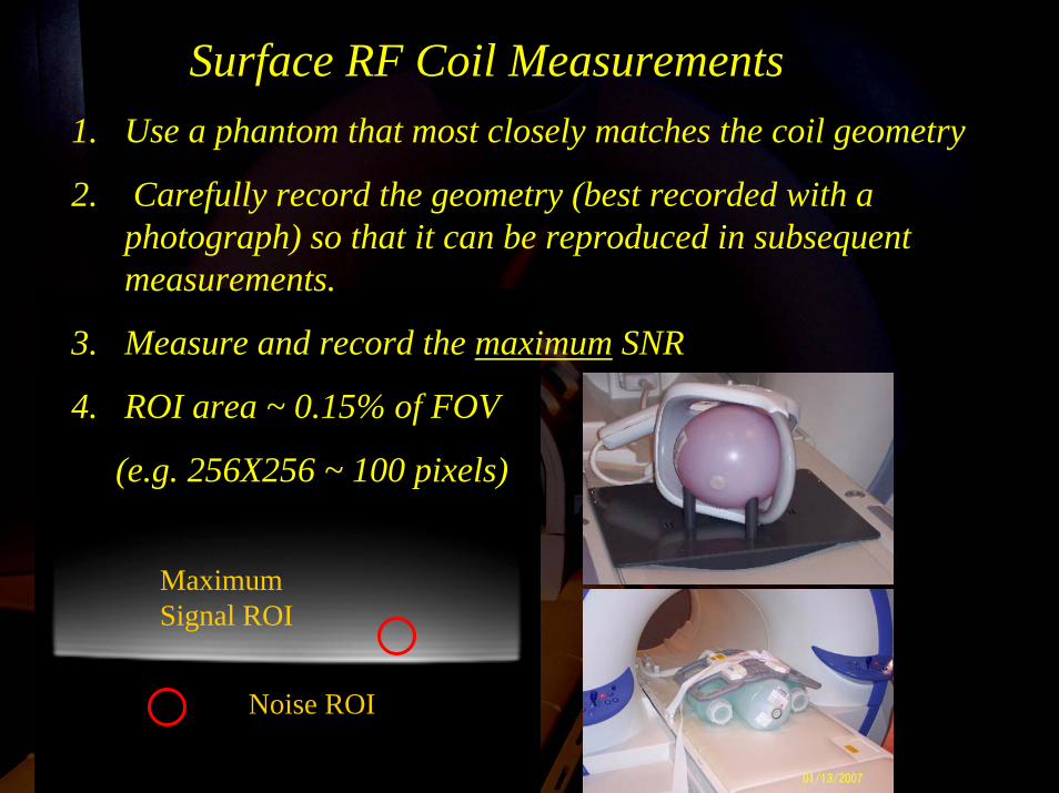
Maximum Signal ROI
Noise ROI
Surface RF Coil Measurements1. Use a phantom that most closely matches the coil geometry
2. Carefully record the geometry (best recorded with a photograph) so that it can be reproduced in subsequent measurements.
3. Measure and record the maximum SNR
4. ROI area ~ 0.15% of FOV
(e.g. 256X256 ~ 100 pixels)

Volume Coil Data
Surface Coil Data
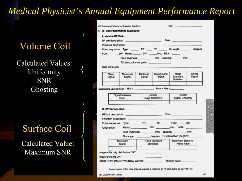
Medical Physicist’s Annual Equipment Performance Report
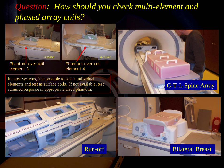
Question: How should you check multi-element and phased array coils?
Run-off Bilateral Breast
C-T-L Spine Array
Phantom over coil element 3
Phantom over coil element 4
In most systems, it is possible to select individual elements and test as surface coils. If not available, test summed response in appropriate sized phantom.
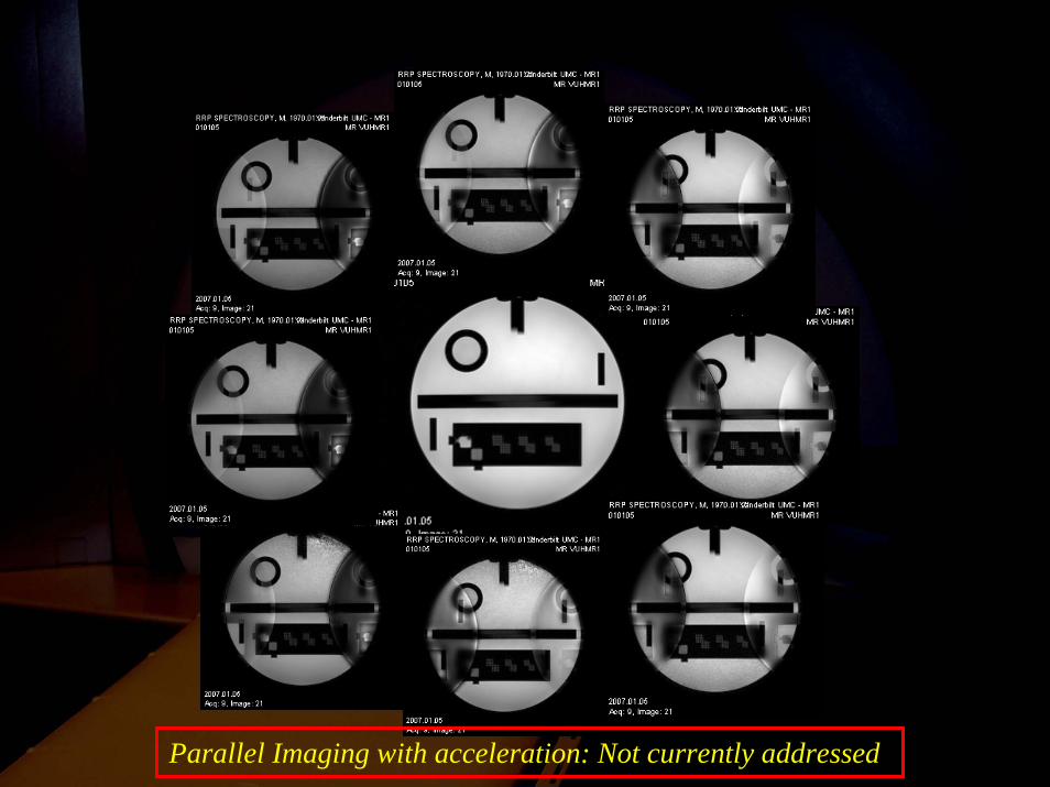
Parallel Imaging with acceleration: Not currently addressed
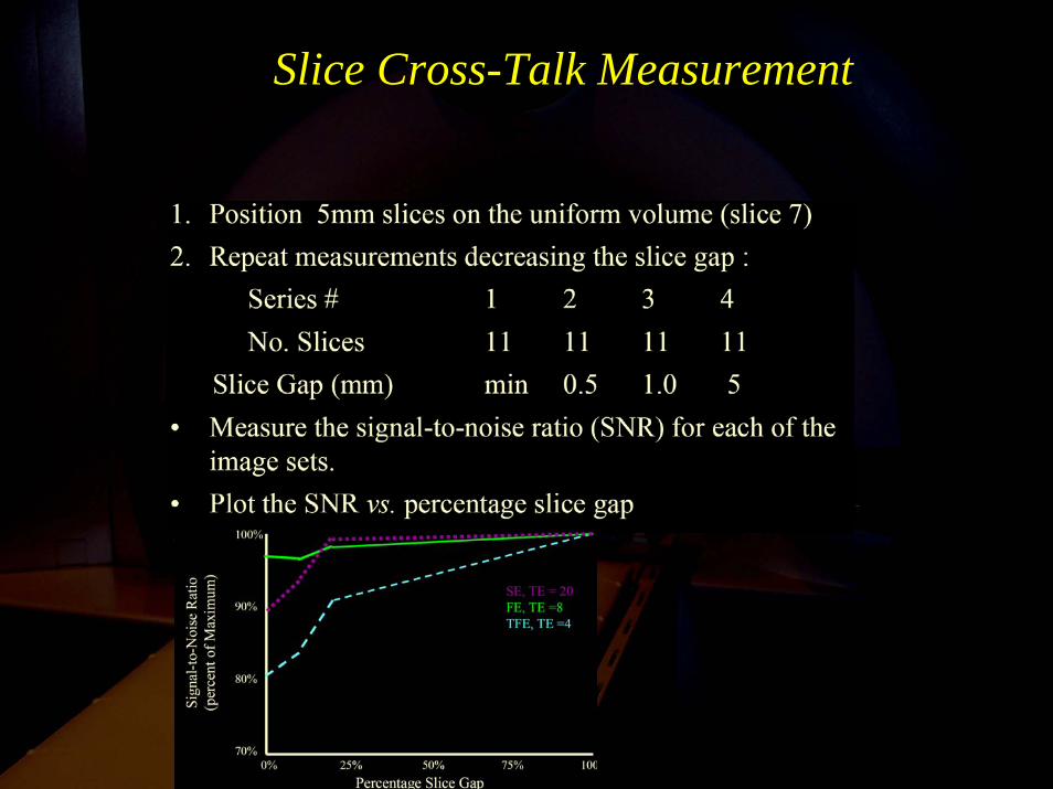
Slice Cross-Talk Measurement
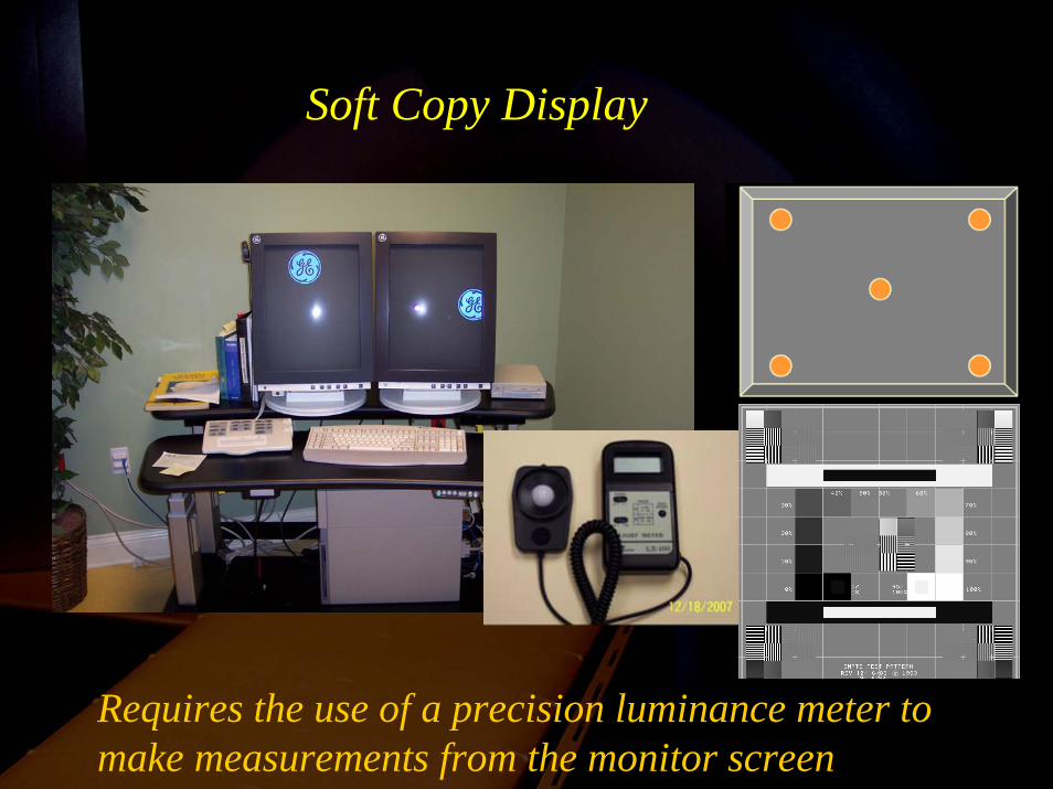
Soft Copy Display
Requires the use of a precision luminance meter to make measurements from the monitor screen
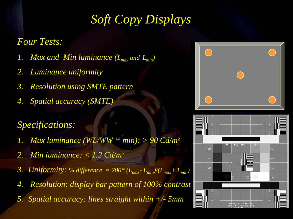
Four Tests:1. Max and Min luminance (Lmax and Lmin)
2. Luminance uniformity
3. Resolution using SMTE pattern
4. Spatial accuracy (SMTE)
Specifications:1. Max luminance (WL/WW = min): > 90 Cd/m2
2. Min luminance: < 1.2 Cd/m2
3. Uniformity: % difference = 200* (Lmax- Lmin)/(Lmax+ Lmin)
4. Resolution: display bar pattern of 100% contrast
5. Spatial accuracy: lines straight within +/- 5mm
Soft Copy Displays
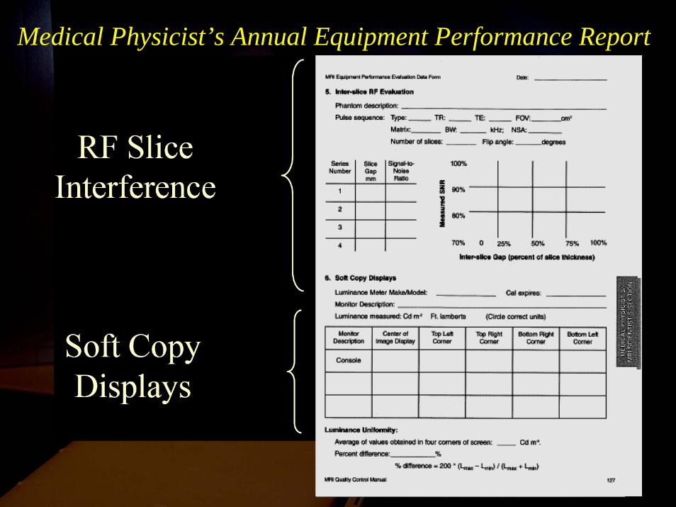
Medical Physicist’s Annual Equipment Performance Report
Medical Physicist’s Annual Equipment Performance Report
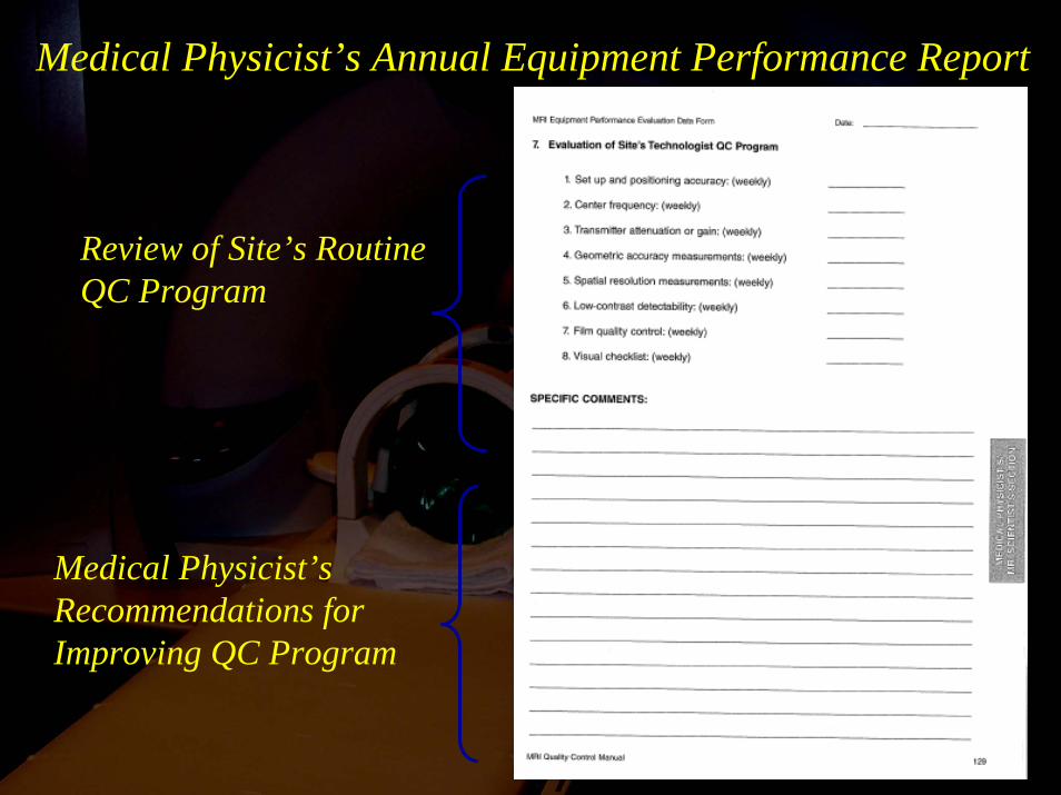
Review of Site’s Routine QC Program
Medical Physicist’s Recommendations for Improving QC Program
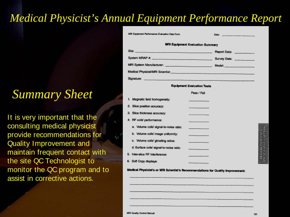
Medical Physicist’s Annual Equipment Performance Report
Summary Sheet
It is very important that the consulting medical physicist provide recommendations for Quality Improvement and maintain frequent contact with the site QC Technologist to monitor the QC program and to assist in corrective actions.
MRI QC Program Summary
Technologist• Performs weekly tests to assess image quality using the ACR phantom
• Performs weekly tests of hard-copy output
• Maintains QC Notebook (Very Important)
Medical Physicist / MR Scientist
• Runs baseline tests of system performance• Sets action limits for weekly ACR phantom tests• Performs annual calibration checks with appropriate
phantoms• Reviews all QC program data (at least annually)
MRI QC Program Summary
MRI QC Program Summary
Radiologist
Ultimately responsible for all QA for the facility
Note:All measurements, problems reported and actions required to resolve the problems must be recorded for review, as must all preventive maintenance and repair records from the vendor or service engineer.
New Requirements: Physician PEER review program and documentation of MRI safety policy.
Special Considerations
Accreditation of “Specialty” systems• Cardiac
• Orthopedic
• Breast
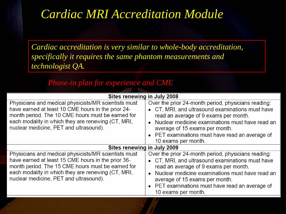
Cardiac MRI Accreditation Module
Phase-in plan for experience and CME
Cardiac accreditation is very similar to whole-body accreditation, specifically it requires the same phantom measurements and technologist QA.

ACR Cardiac MRI Accreditation Module
Some differences in physician qualifications
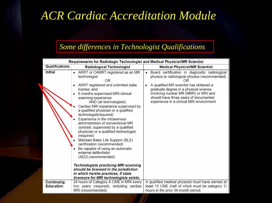
ACR Cardiac Accreditation Module
Some differences in Technologist Qualifications
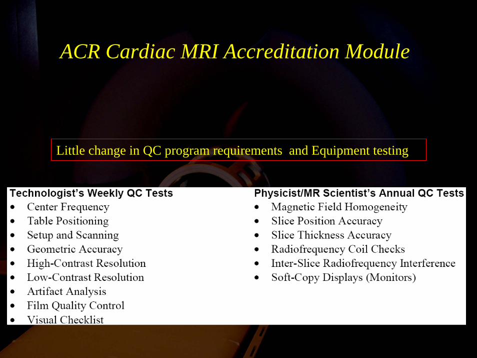
ACR Cardiac MRI Accreditation Module
Little change in QC program requirements and Equipment testing
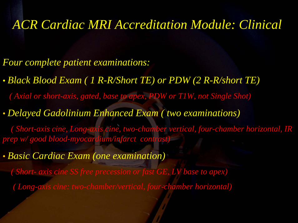
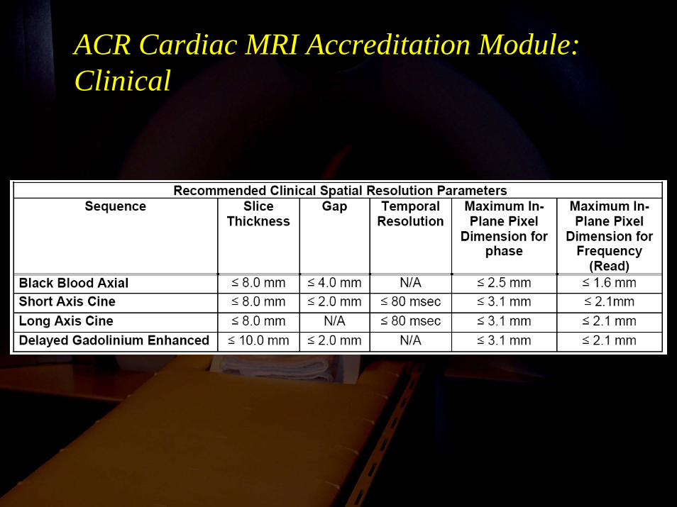
ACR Cardiac MRI Accreditation Module: Clinical
Four complete patient examinations:
• Black Blood Exam ( 1 R-R/Short TE) or PDW (2 R-R/short TE)( Axial or short-axis, gated, base to apex, PDW or T1W, not Single Shot)
• Delayed Gadolinium Enhanced Exam ( two examinations)( Short-axis cine, Long-axis cine, two-chamber vertical, four-chamber horizontal, IR
prep w/ good blood-myocardium/infarct contrast)
• Basic Cardiac Exam (one examination)( Short- axis cine SS free precession or fast GE, LV base to apex)
( Long-axis cine: two-chamber/vertical, four-chamber horizontal)
ACR Cardiac MRI Accreditation Module:Clinical
Introducing the ACR “Small” Phantom for Small-field Orthopedic Systems (Accreditation expected in 2008-2009)
The proposed Orthopedic Module (scheduled for 2008) will utilize a special “Small” phantom for accreditation that will have some changes from the current large phantom.
e.g. Inside length = 100 mm
Inside diameter = 100 mm
High-contrast spatial resolution = 0.7, 0.8 and 0.9 mm holes
Personnel Requirements for Radiologic Technologist
• ARRT or CAMRT registered as an MR technologist, or
• ARRT registered or unlimited state license and 6 months supervised MRI clinical scanning experience, or
• Associate or bachelor degree in allied health field, and certification in another clinical imaging field, and 6 months supervised MRI clinical scanning experience, or
• Performing MRI prior to and continuously since October 1996 and evaluated by responsible physician to assure competence, and
• 15 hours of Category A CME in MRI every three years
[Technologists must be licensed if state licensure for MRI technologists exist]
Technologist Qualifications“Supervised MRI clinical scanning experience” means:
• All training must be documented with clearly defined goals and objectives
• The technologist must be evaluated by the responsible physician
• The technologist must sign an attestation of training and submit to the ACR
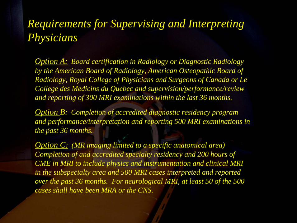
Requirements for Supervising and Interpreting Physicians
Option A: Board certification in Radiology or Diagnostic Radiology by the American Board of Radiology, American Osteopathic Board of Radiology, Royal College of Physicians and Surgeons of Canada or Le College des Medicins du Quebec and supervision/performance/review and reporting of 300 MRI examinations within the last 36 months.
Option B: Completion of accredited diagnostic residency program and performance/interpretation and reporting 500 MRI examinations in the past 36 months.
Option C: (MR imaging limited to a specific anatomical area) Completion of and accredited specialty residency and 200 hours of CME in MRI to include physics and instrumentation and clinical MRI in the subspecialty area and 500 MRI cases interpreted and reported over the past 36 months. For neurological MRI, at least 50 of the 500 cases shall have been MRA or the CNS.


![Relationship Between Internal Derangement of ... Miguel... · 2013 [Relationship Between Internal Derangement of Temporomandibular Joint and Changes in Body Posture] VIII | Escola](https://img.dokumen.tips/doc/110x75/5e9a4966dd2b54332a11340c/relationship-between-internal-derangement-of-miguel-2013-relationship.jpg)