Embed Size (px)
Citation preview

ACR MRI Accreditation Program:
The Technologist’s Role
Geoffrey D. Clarke, Ph.D.University of Texas Health Science Center
at San AntonioRadiological Sciences Division

Overview• ACR MRI Accreditation Program
– Application process & staff requirements
• ACR MRI QC Phantom• Clinical Imaging
– Head, cervical, lumbar & knee
• ACR MRI QC Manual• Technologist’s Responsibilities for QC

ACR MRI Accreditation Program
Overview• Voluntary & Educational in Nature• Evaluates qualifications of personnel• Evaluates equipment performance• Evaluates effectiveness of quality control
measures• Evaluates quality of clinical images

Two-Part Application Process• Review of the entry application
– Credentials of physicians, physicists/MR scientists, and technologists
– Information common to the practice of MRI
• Acquisition of clinical and phantom images– Required clinical images consist of routine brain,
cervical spine, lumbar spine, and knee – Must use a designated MRI phantom – Data must be obtained from each full body general
purpose magnet at the site
• Appeal process if failure

Technologist RequirementsTechnologists performing MRI should:
1. Be certified by ARRT as a MR Technologist,OR
2. Be certified by ARRT and/or state licensure and have 6 months of clinical MRI experience, OR
3. Have an associates degree in an allied health field or a bachelors degree and certification in another clinical imaging field and have 6 months supervised clinical MRI experience
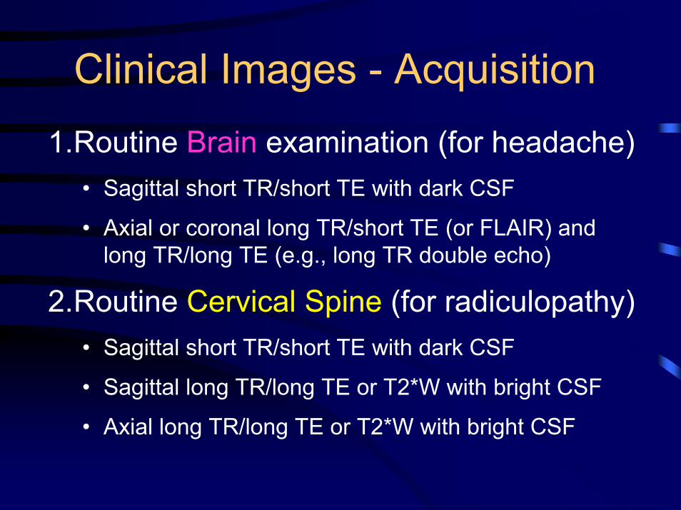
Clinical Images - Acquisition1.Routine Brain examination (for headache)
• Sagittal short TR/short TE with dark CSF
• Axial or coronal long TR/short TE (or FLAIR) and long TR/long TE (e.g., long TR double echo)
2.Routine Cervical Spine (for radiculopathy)• Sagittal short TR/short TE with dark CSF
• Sagittal long TR/long TE or T2*W with bright CSF
• Axial long TR/long TE or T2*W with bright CSF

Clinical Images - Acquisition3. Routine Lumbar Spine (for back pain)
• Sagittal short TR/short TE with dark CSF
• Sagittal long TR/long TE or T2*W with bright CSF
• Axial short TR/short TE with dark CSF and/or long TR/long TE with bright CSF
4. Complete Routine Knee examination (for internal derangement)
• To include sagittal(s) and coronal(s) with at least one sequence with bright fluid

Clinical Images - EvaluationEach set of clinical images will be evaluated for:• Pulse sequences and image contrast. • Filming technique. • Anatomic coverage and imaging planes. • Spatial resolution. • Artifacts. • Exam ID - All patient information annotated
on clinical exams will be kept confidential by the ACR.

Clinical Images - Resolution
< 0.75 mm<1 mm <4 mmKnee
<1.5 mm<1 mm <4 mmL-spine Axial
<1.5 mm <1.5 mm
< 5 mm L-spine Sagittal
<1 mm <1 mm < 3 mmC-spine Axial
<1 mm <1 mm < 3 mmC-spine Sagittal
<1.2 mm< 2 mm
< 5 mm All Brain
Maximum Pixel Dimension
GapSlice Thickness
Sequence

ACR Phantom GoalsACR Phantom Goals• Tests run in a short time• Pulse sequences as compatible
as possible with all commercial MRI scanners
• Specific measurements to account for :– Geometric Distortion– Slice Thickness & Position – Factors Affecting Image SNR
(resolution, bandwidth, ghosting)– Image Uniformity
• Affordable ($730)
• Results easily evaluated
• Affordable ($730)
• Results easily evaluated

Documents for Using PhantomHow to analyze…How to analyze…How to scan…How to scan…
$25 per set from ACR$25 per set from ACR

ACR MRI Accreditation ProgramMRI Survey Agreement
• Official request for ACR Accreditation• Site agrees to provide all
documentation, including but not limited to quality control logs, films, records, or any necessary information requested by the survey team
• Agree to use the ACR MRI phantom

ACRMagnetic
ResonanceImaging QualityControl Manual2001
$57.50 from ACR$57.50 from ACR

Technologist Responsibilities• Designated and trained QC Technologist(s)• Maintain QC Notebook
– QC policies and procedures – data forms where QC test results are recorded – notes on QC problems and corrective actions
• Review QC Data with QA Committee • Only Use Alternative Phantoms & Procedures
when documented by physicist or MRI Scientist• Follow Action Limits Established by Physicist or
MRI Scientist

Technologist’s QC Tasks• Perform image quality tests as
appropriate (at least weekly):– Central Frequency– Signal-to-noise ratio Image Quality
• High contrast resolution• Low contrast detectability
– Image Artifacts• Perform weekly checks of hard copy
fidelity (processor sensitometry)• Weekly visual inspection of equipment

Setting Up Routine Image QC• Daily (weekly)
tests• Develop cheat
sheets to speed process
• System for rapid positioning of phantom
• Daily (weekly) tests
• Develop cheat sheets to speed process
• System for rapid positioning of phantom
TO SET ACTION LIMITS: Review data after first ten days to establish baseline values and variability.TO SET ACTION LIMITS: Review data after first ten days to establish baseline values and variability.

Time to Perform QC• 2 minutes• 1 minute• 3 minutes• 5 minutes*
• 2 minutes*
• 1 minute
• 1 minute
• 1 minutes• 10 minutes• 5 minutes
15 minutes15 minutes
• Set-up Phantom• Center Frequency• Table Positioning• Setup & Scanning• Geometric Accuracy• High Contrast
Resolution• Low Contrast
Resolution• Artifact Analysis• Film Quality Control• Visual Checklist
* Geometric accuracy analysis on sagittal is done while scanning axial* Geometric accuracy analysis on sagittal is done while scanning axial

Central Frequency & Transmitter Gain
• Record center frequency value on ACR phantom or manufacturer’s phantom
• Reflects power required to optimize RF pulse:– Depends on coil, phantom, pulse sequence, etc.
– Should remain constant over time if nothing in pulse sequence or hardware has changed

Tranasmitter Gain Terminology Varies• GE: displayed on screen (dB)• Philips: under system performance
parameters– rf_act_drivescale
• Siemens: “options” – “adjustments”– Frequency– Transmitter amplitude (temp) (V)
• Toshiba: “acquisition window”– Center frequency (MHz)– RF level

Geometric Accuracy
• Measure distance along main axes of phantom
• Compare with known values

Geometric Accuracy - AxialBW = 7.4 kHz BW = 3.6 kHz
Slice #1Slice #1
Failure Due To: • Miscalibrated Gradients• Low Receiver Bandwidth• High Bo Inhomogeneities

Percent Geometric Distortion T1-Weighted, Central Slice
10.00%
8.00%
6.00%
4.00% Poor Gradient Poor Gradient CalibrationCalibration
2.00%
0.00%1- 31- 30-
Oct Oct Nov Dec30- 29- 28-
Jan Feb Mar29- 28- 28- 27- 27- 26-
Apr May Jun Jul Aug Sep25- 25-
Oct
Date of Measurement
System #1 System #2 System #3

Assessment of MR Image Quality
• Using ACR Phantom– High Contrast
Resolution
– Low Contrast Detectability(also used for SNR)
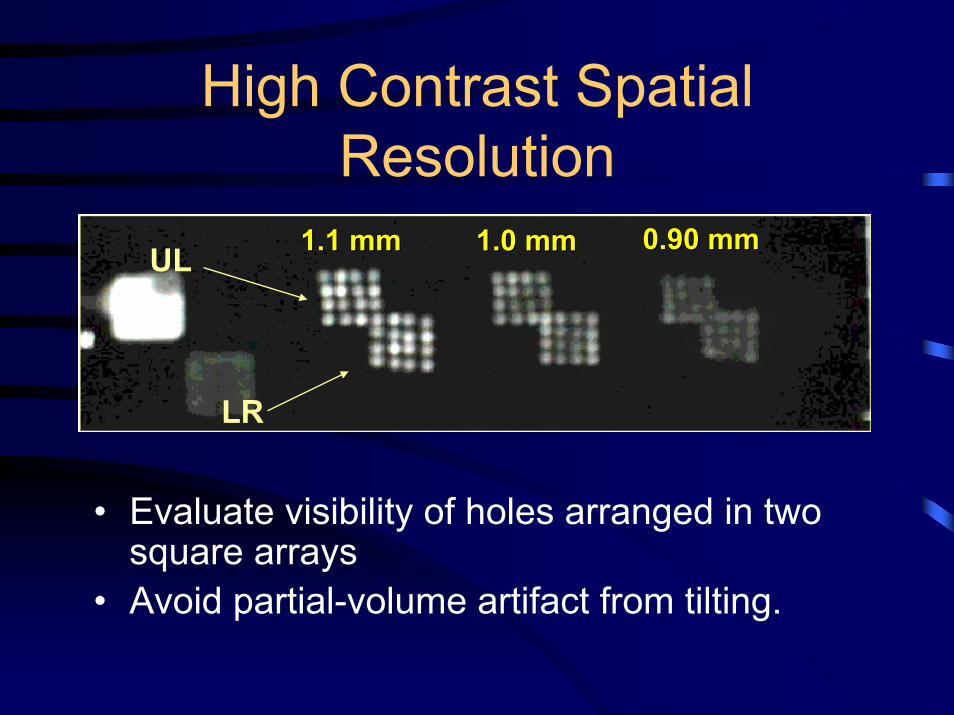
High Contrast Spatial Resolution
UL
LR
1.1 mm1.1 mm 1.0 mm1.0 mm 0.90 mm0.90 mm
• Evaluate visibility of holes arranged in two square arrays
• Avoid partial-volume artifact from tilting.

High Contrast ResolutionHigh Contrast Resolution
•Specific but not sensitive•Action Criteria:
Any reduction in # of holes seen• Suggestive of:
Increased eddy currentsPoor gradient calibrationPoor Bo uniformityReduced stability of system
•Specific but not sensitive•Action Criteria:
Any reduction in # of holes seen• Suggestive of:
Increased eddy currentsPoor gradient calibrationPoor Bo uniformityReduced stability of system
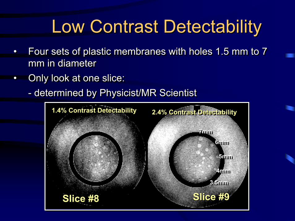
Low Contrast DetectabilityLow Contrast Detectability• Four sets of plastic membranes with holes 1.5 mm to 7
mm in diameter• Only look at one slice:
- determined by Physicist/MR Scientist
•• Four sets of plastic membranes with holes 1.5 mm to 7 Four sets of plastic membranes with holes 1.5 mm to 7 mm in diametermm in diameter
•• Only look at one slice: Only look at one slice: -- determined by Physicist/MR Scientistdetermined by Physicist/MR Scientist
Slice #8Slice #8 Slice #9Slice #9
1.4% Contrast Detectability1.4% Contrast Detectability1.4% Contrast Detectability 2.4% Contrast Detectability2.4% Contrast Detectability2.4% Contrast Detectability
7mm7mm
6mm6mm
5mm5mm
4mm4mm
3.5mm3.5mm

Low Contrast Detectability1.5 T System: T1-Weighted Scan
0.00
5.00
10.00
15.00
20.00
25.00
1-May 31-May 30-Jun 30-Jul 29-Aug 28-Sep 28-Oct 27-Nov 27-Dec 26-Jan 25-Feb 27-Mar 26-Apr
Date
Hole
Siz
e Vi
sual
ized
(mm
)
1.4% contrast
2.4% contrast
3.7% contrast5.1% contrast

Low Contrast DetectabilityACR Slice #8 (1.4% Contrast)
0
2
4
6
8
10
7/1/1998 8/20/1998 10/9/1998 11/28/1998
1/17/1999 3/8/1999 4/27/1999 6/16/1999 8/5/1999
Date
Num
ber o
f Hol
e Se
ts
System #1 System #2 System #3
System #3 Grad Amp Bad Another New Gradient AmpAnother New Gradient Amp
MiniUpgrade
MiniUpgrade
Bad SlicePositioningBad Slice
Positioning

Measurement of System SNR
• Can be performed by technologist• Method to be used
– Manufacturer’s method– ACR method
• Automated analysis and recording often available on modern MRI systems

LCD and Signal-to-NoiseTo
tal N
umbe
r of S
poke
sTo
tal N
umbe
r of S
poke
s
0 50 100 150 200 250 300 3500 50 100 150 200 250 300 350
40
35
30
25
20
15
10
5
0
40
35
30
25
20
15
10
5
0
Signal-to-Noise RatioSignal-to-Noise Ratio

Artifact Evaluation• Check for:
– Distortion?– Ghosts in phantom or
background?– Streaks?– Bright or dark spots?– New features?
Ghosting in phantomGhosting in phantom

Artifacts
Good Scan
DropOut
Spike
DCOffset

ACR MRI StandardHardcopy Image QC Tests
• Sensitometric Measurements for Film Processors
• Hard Copy of SMPTE test pattern • Similar to process used for
mammography program• Laser camera film less sensitive to
temperature changes

Laser Film QCWeekly:View SMPTE patternVerify gray levels• 0/5% & 95/100%
patchesFilm 6 on 1• 4 on 1 if necessaryPlot OD of • 10%, 40% & 90&
patchesObserve film for
artifacts
Weekly:View SMPTE patternVerify gray levels• 0/5% & 95/100%
patchesFilm 6 on 1• 4 on 1 if necessaryPlot OD of • 10%, 40% & 90&
patchesObserve film for
artifacts
SMPTE Test PatternSMPTE Test Pattern

Action Limits
±0.080.3090%
±0.151.1540%
±0.152.1010%
±0.152.450
Control Limit
ODSMPTE patch

Quality Control Program Records• Data form for daily (weekly) equipment
quality control – ACR MRI QC manual, pg. 64
• MRI Facility quality control visual checklist– ACR MRI QC manual, pg. 65
• Laser film printer control chart– ACR MRI QC manual, pg. 66

If QC Test Fails….• Common errors-
– Check for magnetic objects in bore
– Check connections and reseat head coil
– Reposition & landmark phantom
– Make sure scan room door securely closed
• Repeat QC scan procedures
• Record results again in QC notebook
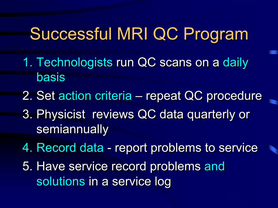
Successful MRI QC ProgramSuccessful MRI QC Program1. Technologists run QC scans on a daily
basis2. Set action criteria – repeat QC procedure3. Physicist reviews QC data quarterly or
semiannually4. Record data - report problems to service 5. Have service record problems and
solutions in a service log
1. Technologists run QC scans on a daily basis
2. Set action criteria – repeat QC procedure3. Physicist reviews QC data quarterly or
semiannually4. Record data - report problems to service 5. Have service record problems and
solutions in a service log


![QuantifyingTumorVascularHeterogeneitywithDynamic Contrast ... · 2015. 7. 29. · ACR Breast Imaging-Reporting and Data System (BI-RADS) MRI lexicon [18]. In cancer treatment, tumor](https://img.dokumen.tips/doc/110x75/5fc9df59a8ef470c23133cae/quantifyingtumorvascularheterogeneitywithdynamic-contrast-2015-7-29-acr.jpg)